JP3870553B2 - Automatic ticket gate - Google Patents
Automatic ticket gate Download PDFInfo
- Publication number
- JP3870553B2 JP3870553B2 JP15742798A JP15742798A JP3870553B2 JP 3870553 B2 JP3870553 B2 JP 3870553B2 JP 15742798 A JP15742798 A JP 15742798A JP 15742798 A JP15742798 A JP 15742798A JP 3870553 B2 JP3870553 B2 JP 3870553B2
- Authority
- JP
- Japan
- Prior art keywords
- detection
- ticket gate
- traffic
- passage
- data
- Prior art date
- Legal status (The legal status is an assumption and is not a legal conclusion. Google has not performed a legal analysis and makes no representation as to the accuracy of the status listed.)
- Expired - Fee Related
Links
Images


Description
【0001】
【発明の属する技術分野】
この発明は、例えば鉄道、空港等の改札口に設置されるような自動改札機に関し、さらに詳しくは大きさが異なる大人、子供さらに挙動の大きい通行者を正確に検知する自動改札機に関する。
【0002】
【従来の技術】
一般に、この種の自動改札機は改札機本体の通路内面に配設した複数の光電検知センサで通行者の通行状態を検知している。
また、係員窓口に隣設する等の自動改札機の設置位置によっては、図15に示すように、バーレス型の改札機本体151を設け、これより検知方向を水平方向ではなく、改札通路152の中央上部に向けて検知方向を傾斜設定した高さ検知用の傾斜検知センサ153…より通路中央を適正に通行する適正通行者154を検知している。
【0003】
ところが、この場合は改札通路152の片側に通行者が偏って通行した偏り通行者155のとき、一方の傾斜検知域153aより外れて人と検知できなくなる。また、無賃許容された幼児や子供156が偏り通行した場合も、他方の傾斜検知域153bに入って大人と誤検知してしまう。
【0004】
このように自動改札機に用いられる高さ検知用の傾斜検知センサで検知した場合、この検知出力がON/OFFの2値で捉えて有料客の有無のみを検知するため、検知領域の調整を厳密に設定しないと、自動改札機の通路外の物や人などにより検知センサの誤検知を招いて自動改札機が誤動作する恐れがある。また、横に並んで通行する無料小児2人を有料客1人と誤判断して扉が不測に通行者に当ってしまう恐れがあった。
【0005】
【発明が解決しようとする課題】
そこでこの発明は、通行体の有無を検知するだけでなく、検知センサから通行体までの検知距離を検知条件に取入れることにより、この検知距離から偏り通行や子供並び通行等の様々な通行者の通行状態を正確に検知する安全性を高めた自動改札機の提供を目的とする。
【0006】
【課題を解決するための手段】
請求項1記載の発明は、改札通路を通行する通行体を検知する検知センサの通行検知データに基づいて改札制御する自動改札機であって、上記検知センサは、斜め上方または略水平に検知して上記通行検知データを取得する構成とし、取得した上記通行検知データに基づいて通行体までの通路幅方向の検知距離を算出する測定手段と、上記検知距離が、上記検知センサ近くの内部無効検知領域と上記改札通路より外部空間の外部無効検知領域とを除いた有効検知距離内にあれば、上記通行検知データを有効であると判定する判定手段とを備えたことを特徴とする。
【0007】
請求項2記載の発明は、上記検知センサは、斜め上方に検知して上記通行検知データを取得し、上記測定手段は、上記通行検知データに基づいて通行体の高さも算出し、上記判定手段は、上記判定の条件を満たし、かつ、上記高さが予め設定されている有料高さ以上であれば、上記通行検知データを有効であると判定することを特徴とする。
【0008】
請求項3記載の発明は、上記検知センサを上記改札通路の左右両側に備え、上記測定手段は、左右両側の上記検知センサによる上記通行検知データに基づいて通行体の横幅も算出し、上記判定手段は、上記判定の条件を満たし、かつ、上記横幅が改札利用を許可する人数分の横幅であれば、上記通行検知データを有効であると判定することを特徴とする。
【0009】
請求項4記載の発明は、上記判定手段は、上記通路幅方向の検知距離に基づいて通行体が改札通路の中央部を通行しているか否か判定し、中央部を通行していると判定した場合に適正な改札利用状態であると判定することを特徴とする。
【0010】
【発明の作用及び効果】
この発明によれば、改札通路を通行する通行体を検知センサが検知したとき、通行体までの検知距離を測定手段が算出し、該検知距離が、上記検知センサ近くの内部無効検知領域と上記改札通路より外部空間の外部無効検知領域とを除いた有効検知距離内にある場合だけ通行検知データを有効と判定する。従って、適正な通行利用のときは適正通行状態と判定し、これ以外の場合は無効データとして取扱い、検知データを正確に取扱うことができる。
【0011】
また、通行体までの検知距離を算出したとき、これに基づいて通行体の高さを算出し、この高さ算出結果に応じて通行体の有効性を判定するように設定すれば、身長差の異なる大人と子供の区別が的確に判断できる。
【0012】
また、通行体までの検知距離を算出したとき、これに基づいて通行体の横幅を算出し、この横幅算出結果に応じて通行体の有効性を判定するように設定すれば、通行体の横幅を正確に捉えることができる。
【0013】
さらに、通行体までの検知距離を算出したとき、これに基づいて通行体の幅方向通行位置を求め、この通行位置に応じて通行体の有効性を判定するように設定すれば、通行体の幅方向の通行状態を正確に検知することができる。
【0014】
このように通行体までの検知距離を検知条件として通行体を検知する高検知能力を有する構成のため、厳密な検知領域の調整を要せず、誤検知や誤動作を自然に解消して安全性の高い自動改札ができる。
【0015】
【実施例】
この発明の一実施例を以下図面に基づいて詳述する。
図1はバーレス型自動改札機11を示し、このバーレス型自動改札機11は左右に対向する一方の改札機本体12と、他方の改札機本体13との対設部間で改札通路14を構成し、双方の改札機本体12,13の両端部の通路内面には開閉動作する扉15…を配設し、さらに通路右側に位置する改札機本体13の上面手前側には切符や定期券等の乗車券を投入する券投入口16を開口し、上面奥側には乗車券を放出する券放出口と改札利用案内を表示する案内表示器とを有している。
【0016】
さらに、各改札機本体12,13の上部には、これより改札通路14の斜め上方に向けて光電検知する反射型の上部検知センサSr,Slを配設し、左右両側から改札通路14の上部空間を光電検知する。
【0017】
この場合、双方の上部検知センサSr,Slは改札通路14の中央上部空間を有効検知領域A1 に設定し、この有効検知領域A1 に向けて各傾斜検知光線17,18が光電検知する。この有効検知領域A1 以外の検知無効となる外部空間を外部無効検知領域A2 に設定し、またセンサ近くの検知無効となる壁面近傍を内部無効検知領域A3 に設定している。
【0018】
この有効検知領域A1 の設定に際しては、傾斜検知光線17,18の有効検知距離を測定して設定する。
有効検知領域A1 に相当する有効検知距離:L1
外部無効検知領域A2 に相当する外部無効検知距離:L2
内部無効検知領域A3 に相当する内部無効検知距離:L3
とすると、この有効検知距離L1 は、
L3 <L1 <L2
で求められる。
【0019】
このため、有効検知距離L1を測定したときだけ有効データとして取扱い、これ以外の外部無効検知距離L2以上、内部無効検知距離L3以下の場合は無効データとして取扱うため、検知したときのデータを正確に取扱うことができる。従って、改札通路14を検知したとき、検知データの検知要素を自動的に選択して適正なデータであることを確認して検知することができる。
【0020】
また、このバーレス型自動改札機11は改札通路14を双方向から改札許容する共用改札機能を有しており、通行者が正通行方向および逆通行方向のいずれの通過方向でも同様な検知機能が働いて通行者を正確に検知する。
【0021】
図2はバーレス型自動改札機11の制御回路ブロック図を示し、CPU21はROM22に格納されたプログラムに沿って各回路装置を制御し、その制御データをRAM23で読出し可能に記憶する。
【0022】
左右両側に配設された上部検知センサSr,Slでその斜め上方の改札通路上部空間の通行状態を検知し、同じく改札通路14の下部内面に配設された下部検知センサ24で改札通路下部空間の通行状態を検知する。また、通行者の改札案内情報を改札機本体の上面に配設された案内表示器25で表示する。
【0023】
乗車券処理部26は、券投入口16に投入された乗車券の磁気データを読取ってその有効性を判定し、有効と判定したとき磁気データ処理、印刷処理、パンチ穴形成等の券処理動作を実行する。また、入口扉処理部27及び出口扉処理部28は、CPU21の扉制御信号に基づいて各扉15…を開閉操作し、改札利用する通行者を通行許容・規制する。
【0024】
ところで、CPU21は左右の上部検知センサSr,Slが検知データを取得したとき、これと同時にセンサから検知位置までの検知距離を算出し、この算出した値が有効検知距離L1 と認められると、検知データを有効と判定し、適正な検知対象物を確認してから検知動作する。またそのときの、改札通路を通行する通行者の身長、横幅等の体格と通路幅方向の通行位置を正確に求めることができる。従って、改札通路14を利用した通行者だけを特定して捉え、しかもその通行状態を正確に検知することができる。
【0025】
このように構成されたバーレス型自動改札機11の改札処理動作を図3のフローチャートを参照して説明する。
今、通行者が改札通路14を通行して改札利用するとき、下部検知センサ24だけでなく、上部検知センサSr,Slが通行者を検知し、このときCPU21は上部検知データに基づいて同センサSr,Slの通路側面から通行者までの通路幅方向の検知距離を算出し(ステップn1 )、
この算出した検知距離の結果が適正な有効検知距離L1 で検知された有効検知領域A1 に通行者が存在すると判定すると(ステップn2 〜n3 )、
CPU21は改札通路14を通行する正規の検知すべき通行者であると判定して通行者を確認して正確に検知することができる(ステップn4 〜n5 )。
【0026】
CPU21が上部検知センサSr,Slの検知距離を算出したとき、改札通路14より外部の外部無効検知距離L2以上のときは有効検知距離L1を外れているため無効データとして取扱い、同じく改札通路14より手前のセンサ近くの内部無効検知距離L3以下のときは有効検知距離L1 を外れているため無効データとして取扱う(ステップn6 〜n7 )。
【0027】
図4は片バーレス型自動改札機41を示し、この片バーレス型自動改札機41は一方のバー付き改札機本体42の上部に起立したバー43に反射型の上部検知センサ44を取付け、この上部検知センサ44から改札通路45の上部空間を略水平に光電検知する。
【0028】
この場合も同様に、有効検知領域A1 の設定に際しては、水平検知光線46の有効検知距離を測定して設定する。
有効検知領域A1 に相当する有効検知距離:L1
外部無効検知領域A2 に相当する外部無効検知距離:L2
内部無効検知領域A3 に相当する内部無効検知距離:L3
とすると、この有効検知距離L1 は、
L3 <L1 <L2
で求められる。
【0029】
このように片バーレス型自動改札機41に適用しても、検知距離を検知条件に設定しているため、検知データを正確に取扱って同様の作用効果が得られる。
【0030】
図5はバー型自動改札機51を示し、このバー型自動改札機51は一方の改札機本体52の上部に起立したバー53に反射型の上部検知センサ54を取付け、この上部検知センサ54から改札通路55の上部空間に向けて光電検知する。
【0031】
この場合も同様に、有効検知領域A1 の設定に際しては、水平検知光線56の有効検知距離を測定して設定する。
有効検知領域A1 に相当する有効検知距離:L1
外部無効検知領域A2 に相当する外部無効検知距離:L2
内部無効検知領域A3 に相当する内部無効検知距離:L3
とすると、この有効検知距離L1 は
L3 <L1 <L2
で求められる。
【0032】
このようにバー型自動改札機51に適用しても、検知距離を検知条件に設定しているため、検知データを正確に取扱って同様の作用効果が得られる。
【0033】
次に、バーレス型自動改札機11を用いて有料客1人が改札利用した場合と、無料小児2人が同時改札利用した場合の処理動作を図6のフローチャートを参照して説明する。
今、通行者が改札利用するとき、下部検知センサ24に加えて上部検知センサSr,Slが通行時の検知データを取得し、このときCPU21は上部検知データに基づいて同センサSr,Slの通路側面から通行者までの通路幅方向の検知距離を算出し(ステップn11〜n12)、
さらに、この算出した検知距離に基づいてCPU21は通行者の高さを算出する。この場合、図7に示すように、左右から得られる両検知距離のデータに基づいて通行者71が1人分の横幅Wであるか否かと、通行者71が有料高さH以上の身長か否かを判定し(ステップn13〜n14)、
通行者が1人分の横幅Wを有し、かつ有料高さH以上の身長を有していると判定すれば、有料客1人の改札利用と確認して改札利用させる(ステップn15)。 このとき、有料客が無券で改札利用すると判定した場合は、出口側の扉を閉じて改札規制する(ステップn16〜n18)。
【0034】
これに対し、有料客による乗車券利用がなされた場合は、その乗車券データによる改札利用が行われる(ステップn19)。
【0035】
左右の上部検知センサSr,Slが有料高さ以下の通行者と検知した場合は、その左右の検知データを比較し(ステップn20)、
一方の上部検知センサのデータだけしか得られない場合は、無料小児1人が改札利用したと判定する(ステップn21)。
【0036】
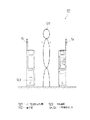
これに対し、左右の上部検知センサSr,Slの検知データが得られた場合、図8に示すように、左右から得られる両検知距離のデータに基づいて通行者81は並列する小児客2人分の横幅Wであることを確認して、無料小児2人が同時改札利用したと判定する(ステップn22)。
【0037】
従って、この場合は並列する無料小児2人が改札通路14を通過するまで、扉15を開保持して改札通路を安全に通行させる(ステップn23)。
【0038】
次に、図9及び図10に示すバー型自動改札機91を用いて有料客1人が改札利用した場合と、有料客2人が同時改札利用した場合の処理動作を図11のフローチャートを参照して説明する。
今、通行者92が改札通路93を改札利用するとき、下部検知センサに加えて上部検知センサSr,Slが通行時の検知データを取得し、このときCPUは上部の検知データに基づいて同センサSr,Slの通路側面から通行者までの通路幅方向の検知距離を算出し(ステップn31〜n32)、
さらに、この算出した検知距離に基づいてCPUは左右から得られる両検知距離のデータに基づいて通行者が1人分の横幅W1 であるか否かを判定し(ステップn33〜n34)、
図9に示すように、1人分の横幅W1 と判定すれば、有料客1人の改札利用と確認する(ステップn35)。
【0039】
これに対し、図10に示すように、通行者101が2人分の横幅W2 と判定すれば、有料客2人の並列改札利用と確認する(ステップn36)。
そして、有料客1人が乗車券を投入利用した場合は、その乗車券データによる改札利用が行われる(ステップn37〜n39)。
【0040】
これに対し、有料客2人の並列改札利用がなされた場合は、乗車券が2人分投入されたか否かを確認し、2人分投入されたことを確認すれば、有料客2人の並列改札利用を許可する(ステップn40)。
この並列改札利用時に、乗車券が1人分しか投入されない場合は、有料客2人の不正改札利用と判定して改札規制し、また有料客1人でも無効乗車券の場合は改札規制する(ステップn41)。
【0041】
次に、図12及び図13に示すバー型自動改札機121を用いて有料客が改札利用した場合の処理動作を図14のフローチャートを参照して説明する。
今、通行者122が改札通路123を改札利用するとき、下部検知センサに加えて上部検知センサSr,Slが通行時の検知データを取得し、このときCPUは上部の検知データに基づいて同センサSr,Slの通路側面から通行者までの通路幅方向の検知距離を算出し(ステップn51〜n52)、
このとき、算出した検知距離からCPUは通行者122が改札通路123の中央部を通行しているか否かを判定し(ステップn53)、
図12に示すように、通行者122が改札通路123の中央部を通行していると判定した場合は、適正な改札利用状態のため左右の扉を同期させた通常の開閉制御を行って改札許容、あるいは改札規制する(ステップn54)。
【0042】
これに対し、通行者122が改札通路123の幅方向を偏って通行した場合、例えば改札通路123の右側に偏って通行していると判定した場合は、その通行者に対する改札規制を必要としたときに右側の扉の閉速度を遅くし、通行者の通行状態に応じた扉開閉制御を行い、通行者の安全性を図った改札規制を行う(ステップn55〜n56)。
【0043】
また、図13に示すように、通行者122が改札通路123の左側に偏って通行していれば、改札規制を必要としたときに左側の扉の閉速度を遅くし、通行者の通行状態に応じた扉開閉制御を行い、通行者の安全性を図った改札規制を行う(ステップn57)。このような扉の遅閉動作を行う以外に、扉の閉角度を変更するなどして、通行者の通路幅方向の通行位置に対応した扉の開閉制御を行うことができるため、通行者が扉に当る危険性を低くすることができる。
【0044】
上述のように、一定の領域に区画された改札通路内を上部検知センサが検知したとき、これと同時に通路側面から被検知対象物までの通路幅方向の検知距離を測定し、この検知距離測定結果に基づいて検知データが有効か無効かを判定することができるため、適正な検知データであることを予め確認することができる。このため、改札通路を通行する通行者の高さ、通行者の幅及び通路幅方向の通行位置が正確に分り、通行者の通行状態を正確に検知して自動改札機の開閉動作を正確に行うことができる。ことに、通行者の有効検知距離を測定したときだけ通行検知データを有効と判定して取扱えば、適正な通行利用のときは適正通行状態と判定し、これ以外の無効検知距離の場合は無効データとして取扱うことができる。
【0045】
また、通行者までの検知距離を測定したとき、これに基づいて通行者の高さを算出し、この高さ算出結果に応じて通行者の有効性を判定すれば、身長差の異なる大人と子供の区別が的確に判断できる。また、通行者までの検知距離を測定したとき、これに基づいて通行者の横幅を算出し、この横幅算出結果に応じて通行者の有効性を判定すれば、通行者の横幅を正確に捉えることができる。さらに、通行者までの検知距離を測定したとき、これに基づいて通行者の幅方向通行位置を求め、この通行位置に応じて通行者の有効性を判定すれば、通行者の幅方向の通行状態を正確に検知することができる。このように通行者までの検知距離を検知条件として通行者を検知する高検知能力を有する構成のため、厳密な検知領域の調整を要せず、誤検知や誤動作を自然に解消して安全性の高い自動改札ができる。
【0046】
この発明と、上述の一実施例の構成との対応において、
この発明の自動改札機は、実施例のバーレス型自動改札機11と、片バーレス型自動改札機41と、バー型自動改札機51,91,121とに対応し、
以下同様に、
通行体は、通行者92,122に対応し、
検知センサは、上部検知センサSr,Sl,44,54に対応し、
測定手段及び判定手段は、CPU21に対応するも、この発明は請求項に示される技術思想に基づいて応用することができ、上述の一実施例の構成のみに限定されるものではない。
【図面の簡単な説明】
【図1】 この発明のバーレス型自動改札機の検知状態を示す正面図。
【図2】 この発明のバーレス型自動改札機の制御回路ブロック図。
【図3】 この発明のバーレス型自動改札機の改札処理動作を示すフローチャート。
【図4】 この発明の片バーレス型自動改札機の検知状態を示す正面図。
【図5】 この発明のバー型自動改札機の検知状態を示す正面図。
【図6】 この発明のバーレス型自動改札機の改札処理動作を示すフローチャート。
【図7】 この発明のバーレス型自動改札機の有料客1人の検知状態を示す正面図。
【図8】 この発明のバーレス型自動改札機の無料小児2人の検知状態を示す正面図。
【図9】 この発明のバー型自動改札機の有料客1人の幅検知状態を示す正面図。
【図10】 この発明のバー型自動改札機の有料客2人の検知状態を示す正面図。
【図11】 この発明のバー型自動改札機の改札処理動作を示すフローチャート。
【図12】 この発明のバー型自動改札機の有料客中央通行検知状態を示す正面図。
【図13】 この発明のバー型自動改札機の有料客片寄り通行検知状態を示す正面図。
【図14】 この発明のバー型自動改札機の改札処理動作を示すフローチャート。
【図15】 従来のバーレス型の自動改札機の検知状態を示す正面図。
【符号の説明】
11…バーレス型自動改札機
14,45,55,93,123…改札通路
Sr,Sl,44,54…上部検知センサ
A1 …有効検知領域
A2 …外部無効検知領域
A3 …内部無効検知領域
L1 …有効検知距離
L2 …外部無効検知距離
L3 …内部無効検知距離
21…CPU
41…片バーレス型自動改札機
51,91,121…バー型自動改札機
W,W1…1人分の横幅
W2…2人分の横幅
H…有料高さ
71,81,92,101,122…通行者[0001]
BACKGROUND OF THE INVENTION
The present invention relates to an automatic ticket gate such as that installed at a ticket gate of, for example, a railway or an airport. More specifically, the present invention relates to an automatic ticket gate that accurately detects adults, children, and passers with large behaviors having different sizes.
[0002]
[Prior art]
In general, this type of automatic ticket gate detects the pass-by state of a passer by a plurality of photoelectric detection sensors disposed on the inner surface of the passage of the ticket gate body.
Further, depending on the installation position of the automatic ticket gate such as adjacent to the staff counter, as shown in FIG. 15, a barless type ticket gate
[0003]
However, in this case, when the passerby is biased to one side of the
[0004]
In this way, when detected by the inclination detection sensor for height detection used in the automatic ticket gate, this detection output is detected by the binary value of ON / OFF, and only the presence or absence of paying customers is detected, so the detection area is adjusted. If it is not set strictly, there is a possibility that the automatic ticket checker malfunctions due to an erroneous detection of the detection sensor by an object or a person outside the passage of the automatic ticket checker. In addition, there was a risk that two free children traveling side by side were mistakenly judged as one paying customer and the door unexpectedly hit the passerby.
[0005]
[Problems to be solved by the invention]
Therefore, the present invention not only detects the presence or absence of a vehicle, but also incorporates the detection distance from the detection sensor to the vehicle to the detection condition, so that various passers-by such as biased traffic and child-lined traffic can be used. The purpose is to provide an automatic ticket gate with improved safety to accurately detect the traffic state of the car.
[0006]
[Means for Solving the Problems]
The invention according to
[0007]
According to a second aspect of the present invention, the detection sensor detects the traffic detection data obliquely upward, the measurement means calculates the height of the traffic body based on the traffic detection data, and the determination means. Is characterized in that the traffic detection data is determined to be valid if the determination condition is satisfied and the height is equal to or higher than a preset pay height .
[0008]
According to a third aspect of the present invention, the detection sensors are provided on both the left and right sides of the ticket gate, and the measuring means also calculates a lateral width of the vehicle based on the traffic detection data by the detection sensors on the left and right sides, and the determination The means is characterized in that the traffic detection data is determined to be valid if the determination condition is satisfied and the horizontal width is equal to the number of persons permitted to use the ticket gate .
[0009]
According to a fourth aspect of the present invention, the determination means determines whether or not the passing body passes through the central portion of the ticket gate passage based on the detection distance in the passage width direction, and determines that the passage is passing through the central portion. In this case, it is determined that the ticket gate usage state is appropriate .
[0010]
[Action and effect of the invention]
According to the present invention, when the detection sensor detects a passing body that passes through the ticket gate passage, the measurement means calculates the detection distance to the passing body, and the detection distance includes the internal invalid detection area near the detection sensor and the above-described detection distance. The traffic detection data is determined to be valid only when it is within the effective detection distance excluding the external invalidity detection area in the external space from the ticket gate . Therefore , it is determined that the vehicle is in a proper traffic state when it is used appropriately, and in other cases , it is handled as invalid data and the detection data can be handled accurately.
[0011]
Also, when calculating the detection distance to the vehicle, the height of the vehicle is calculated based on this, and if the setting is made to determine the effectiveness of the vehicle according to this height calculation result, the height difference The distinction between adults and children with different age can be accurately judged.
[0012]
Also, when calculating the detected distance to the traffic body, this was calculated the width of the traffic object based, is set to determine the effectiveness of traffic body in accordance with the width calculation result, the width of the passage body Can be accurately captured.
[0013]
Furthermore, when the detection distance to the vehicle is calculated , the width-direction traffic position of the vehicle is calculated based on the detection distance, and if the vehicle is set to determine the effectiveness of the vehicle according to the traffic position, The traffic condition in the width direction can be accurately detected.
[0014]
In this way, because it has a high detection capability to detect a passing object using the detection distance to the passing object as a detection condition, it does not require strict adjustment of the detection area, and it eliminates false detections and malfunctions naturally, and safety High automatic ticket gates are possible.
[0015]
【Example】
An embodiment of the present invention will be described in detail with reference to the drawings.
FIG. 1 shows a barless type
[0016]
Further, reflection type upper detection sensors Sr and Sl for photoelectric detection from the right and left sides of the ticket gate
[0017]
In this case, both upper detection sensors Sr and S1 set the central upper space of the
[0018]
In setting the effective detection area A1, the effective detection distances of the tilt
Effective detection distance corresponding to the effective detection area A1: L1
External invalidity detection distance corresponding to external invalidity detection area A2: L2
Internal invalid detection distance corresponding to internal invalid detection area A3: L3
Then, this effective detection distance L1 is
L3 <L1 <L2
Is required.
[0019]
For this reason, it is handled as valid data only when the effective detection distance L1 is measured, and it is handled as invalid data when the external invalid detection distance is not less than L2 and the internal invalid detection distance is not more than L3. Can be handled. Therefore, when the
[0020]
The barless type
[0021]
FIG. 2 shows a control circuit block diagram of the barless type
[0022]
The upper detection sensors Sr and S1 disposed on the left and right sides detect the passage state of the upper space of the ticket gate passage obliquely above, and the
[0023]
The
[0024]
By the way, when the left and right upper detection sensors Sr and Sl acquire the detection data, the
[0025]
The ticket gate processing operation of the barless type
Now, when a passer-by passes through the
When it is determined that a passerby exists in the effective detection area A1 detected at the appropriate effective detection distance L1 as a result of the calculated detection distance (steps n2 to n3),
The
[0026]
When the
[0027]
FIG. 4 shows a single barless type
[0028]
In this case as well, when setting the effective detection area A1, the effective detection distance of the horizontal
Effective detection distance corresponding to the effective detection area A1: L1
External invalidity detection distance corresponding to external invalidity detection area A2: L2
Internal invalid detection distance corresponding to internal invalid detection area A3: L3
Then, this effective detection distance L1 is
L3 <L1 <L2
Is required.
[0029]
Thus, even if it is applied to the one-barless
[0030]
FIG. 5 shows a bar-type
[0031]
In this case as well, when setting the effective detection area A1, the effective detection distance of the horizontal
Effective detection distance corresponding to the effective detection area A1: L1
External invalidity detection distance corresponding to external invalidity detection area A2: L2
Internal invalid detection distance corresponding to internal invalid detection area A3: L3
Then, this effective detection distance L1 is
L3 <L1 <L2
Is required.
[0032]
Thus, even when applied to the bar-type
[0033]
Next, the processing operation when one paying customer uses the ticket gate and two free children simultaneously using the ticket gate using the barless type
Now, when the passerby uses the ticket gate, the upper detection sensors Sr and Sl in addition to the
Further, the
If it is determined that the passer has a width W for one person and has a height equal to or higher than the paying height H, the ticket gate is confirmed to be used by one paying customer (step n15). At this time, if it is determined that the paying customer uses the ticket gate without a ticket, the gate on the exit side is closed to restrict the ticket gate (steps n16 to n18).
[0034]
On the other hand, when a ticket is used by a paying passenger, a ticket gate is used based on the ticket data (step n19).
[0035]
When the left and right upper detection sensors Sr and Sl detect a passerby whose height is less than or equal to the paid height, the left and right detection data are compared (step n20),
If only the data of one upper detection sensor can be obtained, it is determined that one free child has used the ticket gate (step n21).
[0036]
On the other hand, when the detection data of the left and right upper detection sensors Sr and Sl are obtained, as shown in FIG. 8, the passers-by 81 are two children in parallel based on the data of both detection distances obtained from the left and right. After confirming that the width is equal to W, it is determined that two free children have used the ticket gate simultaneously (step n22).
[0037]
Therefore, in this case, until the two free children in parallel pass through the
[0038]
Next, refer to the flowchart of FIG. 11 for processing operations when one paying customer uses the ticket gate and two paying customers use the ticket gate simultaneously using the bar-type
Now, when the passer-by 92 uses the
Further, based on the calculated detection distance, the CPU determines whether or not a passerby has a lateral width W1 based on both detection distance data obtained from the left and right (steps n33 to n34).
As shown in FIG. 9, if it is determined that the width is W1 for one person, it is confirmed that the ticket gate is used by one paying customer (step n35).
[0039]
On the other hand, as shown in FIG. 10, if the
When one paying passenger uses a ticket, the ticket gate is used based on the ticket data (steps n37 to n39).
[0040]
On the other hand, if two paying passengers use a parallel ticket gate, check whether two tickets have been inserted and confirm that two passengers have been inserted. The use of the parallel ticket gate is permitted (step n40).
If only one ticket is inserted when using this parallel ticket gate, it is determined that two paying passengers are illegally using the ticket gates, and ticket gates are restricted even if one paying passenger is an invalid ticket ( Step n41).
[0041]
Next, processing operations when a paying customer uses a ticket gate using the bar-type
Now, when the passer-
At this time, from the calculated detection distance, the CPU determines whether or not the passer-
As shown in FIG. 12, when it is determined that the passer-
[0042]
On the other hand, when the passer-by 122 passes in the width direction of the
[0043]
Also, as shown in FIG. 13, if the passer-
[0044]
As described above, when the upper detection sensor detects the inside of the ticket gate divided into a certain area, the detection distance in the passage width direction from the side of the passage to the object to be detected is measured at the same time, and this detection distance measurement Since it is possible to determine whether the detection data is valid or invalid based on the result, it can be confirmed in advance that the detection data is appropriate. For this reason, the height of the passers through the ticket gate, the width of the passers and the passage position in the direction of the passage width are accurately known, and the opening / closing operation of the automatic ticket checker is accurately detected by accurately detecting the pass state of the passers. It can be carried out. In particular, if it is determined that the traffic detection data is valid and handled only when the effective detection distance of the passer is measured, it is determined that the traffic is properly used when it is used properly, and invalid for other invalid detection distances. Can be handled as data.
[0045]
In addition, when measuring the detection distance to the passerby, the height of the passer is calculated based on this, and if the effectiveness of the passer is determined according to this height calculation result, Can distinguish children accurately. In addition, when the distance to the passerby is measured, the lateral width of the passer is calculated based on this, and if the passerby's effectiveness is determined according to the result of the lateral width calculation, the lateral width of the passer is accurately captured. be able to. Further, when the detection distance to the passer is measured, the passer's width direction pass position is obtained based on this, and if the passer's effectiveness is determined according to the passer's position, the passer's width pass is determined. The state can be accurately detected. In this way, because it has a high detection capability to detect the passerby using the detection distance to the passerby as a detection condition, it does not require strict adjustment of the detection area, and it eliminates false detections and malfunctions naturally, and safety High automatic ticket gates are possible.
[0046]
In correspondence between the present invention and the configuration of the above-described embodiment,
The automatic ticket gate of the present invention corresponds to the barless type
Similarly,
The passerby corresponds to the passers-by 92, 122,
The detection sensors correspond to the upper detection sensors Sr, Sl, 44, 54,
Although the measurement means and the determination means correspond to the
[Brief description of the drawings]
FIG. 1 is a front view showing a detection state of a barless automatic ticket gate according to the present invention.
FIG. 2 is a control circuit block diagram of a barless type automatic ticket gate according to the present invention.
FIG. 3 is a flowchart showing a ticket gate processing operation of the barless type automatic ticket gate according to the present invention.
FIG. 4 is a front view showing a detection state of the one-barless automatic ticket gate according to the present invention.
FIG. 5 is a front view showing a detection state of the bar type automatic ticket gate according to the present invention.
FIG. 6 is a flowchart showing the ticket gate processing operation of the barless type automatic ticket gate according to the present invention.
FIG. 7 is a front view showing a detection state of one paying customer of the barless type automatic ticket gate according to the present invention.
FIG. 8 is a front view showing a detection state of two free children in the barless type automatic ticket gate according to the present invention.
FIG. 9 is a front view showing a width detection state of one paying customer of the bar type automatic ticket gate according to the present invention.
FIG. 10 is a front view showing a detection state of two paying customers of the bar type automatic ticket gate according to the present invention.
FIG. 11 is a flowchart showing a ticket gate processing operation of the bar type automatic ticket gate according to the present invention.
FIG. 12 is a front view showing a charged customer central traffic detection state of the bar type automatic ticket gate according to the present invention.
FIG. 13 is a front view showing a state where a paid customer side-by-side detection of the bar type automatic ticket gate according to the present invention is detected.
FIG. 14 is a flowchart showing the ticket gate processing operation of the bar type automatic ticket gate according to the present invention.
FIG. 15 is a front view showing a detection state of a conventional barless type automatic ticket gate.
[Explanation of symbols]
11 ... Barless type
41 ... Single barless type
Claims (4)
上記検知センサは、斜め上方または略水平に検知して上記通行検知データを取得する構成とし、
取得した上記通行検知データに基づいて通行体までの通路幅方向の検知距離を算出する測定手段と、
上記検知距離が、上記検知センサ近くの内部無効検知領域と上記改札通路より外部空間の外部無効検知領域とを除いた有効検知距離内にあれば、上記通行検知データを有効であると判定する判定手段とを備えた
自動改札機。An automatic ticket gate that controls ticket gates based on the traffic detection data of a detection sensor that detects a vehicle passing through the ticket gate passage,
The detection sensor is configured to acquire the traffic detection data by detecting obliquely upward or substantially horizontal,
Measuring means for calculating a detection distance in the passage width direction to the passing body based on the acquired traffic detection data ;
Determination that the traffic detection data is valid if the detection distance is within an effective detection distance excluding an internal invalid detection area near the detection sensor and an external invalid detection area outside the ticket gate passage. Automatic ticket gate with means.
上記測定手段は、上記通行検知データに基づいて通行体の高さも算出し、
上記判定手段は、上記判定の条件を満たし、かつ、上記高さが予め設定されている有料高さ以上であれば、上記通行検知データを有効であると判定する
請求項1記載の自動改札機。 The detection sensor detects diagonally upward and acquires the traffic detection data,
The measuring means also calculates the height of the vehicle based on the traffic detection data,
The determination unit determines that the traffic detection data is valid if the determination condition is satisfied and the height is equal to or higher than a preset pay height. Automatic ticket gate.
上記測定手段は、左右両側の上記検知センサによる上記通行検知データに基づいて通行体の横幅も算出し、
上記判定手段は、上記判定の条件を満たし、かつ、上記横幅が改札利用を許可する人数分の横幅であれば、上記通行検知データを有効であると判定する
請求項1または2記載の自動改札機。 The detection sensors are provided on the left and right sides of the ticket gate passage,
The measuring means also calculates the width of the vehicle based on the traffic detection data by the detection sensors on both the left and right sides,
The traffic determination data is determined to be valid if the determination means satisfies the determination condition and the horizontal width is equal to the number of persons permitted to use the ticket gates. Automatic ticket gate as described.
請求項1、2または3記載の自動改札機。 The determination means determines whether or not the vehicle is passing through the central portion of the ticket gate passage based on the detection distance in the passage width direction, and when it is determined that the vehicle is passing through the central portion, an appropriate ticket gate usage state determining <br/> claim 1, 2 or 3 automatic gate according to be the.
Priority Applications (1)
| Application Number | Priority Date | Filing Date | Title |
|---|---|---|---|
| JP15742798A JP3870553B2 (en) | 1998-06-05 | 1998-06-05 | Automatic ticket gate |
Applications Claiming Priority (1)
| Application Number | Priority Date | Filing Date | Title |
|---|---|---|---|
| JP15742798A JP3870553B2 (en) | 1998-06-05 | 1998-06-05 | Automatic ticket gate |
Publications (2)
| Publication Number | Publication Date |
|---|---|
| JPH11353508A JPH11353508A (en) | 1999-12-24 |
| JP3870553B2 true JP3870553B2 (en) | 2007-01-17 |
Family
ID=15649408
Family Applications (1)
| Application Number | Title | Priority Date | Filing Date |
|---|---|---|---|
| JP15742798A Expired - Fee Related JP3870553B2 (en) | 1998-06-05 | 1998-06-05 | Automatic ticket gate |
Country Status (1)
| Country | Link |
|---|---|
| JP (1) | JP3870553B2 (en) |
Families Citing this family (3)
| Publication number | Priority date | Publication date | Assignee | Title |
|---|---|---|---|---|
| JP2006228003A (en) * | 2005-02-18 | 2006-08-31 | Nippon Signal Co Ltd:The | Automated ticket gate |
| JP4811419B2 (en) * | 2008-02-28 | 2011-11-09 | オムロン株式会社 | Gate device |
| JP5617707B2 (en) * | 2011-03-16 | 2014-11-05 | 株式会社デンソーウェーブ | Entrance / exit management system |
-
1998
- 1998-06-05 JP JP15742798A patent/JP3870553B2/en not_active Expired - Fee Related
Also Published As
| Publication number | Publication date |
|---|---|
| JPH11353508A (en) | 1999-12-24 |
Similar Documents
| Publication | Publication Date | Title |
|---|---|---|
| JP3870553B2 (en) | Automatic ticket gate | |
| JP3784897B2 (en) | Automatic ticket gate | |
| JP2005031841A (en) | Automatic ticket gate device | |
| JP2004227294A (en) | Automatic ticket gate | |
| JP3728863B2 (en) | Automatic ticket gate | |
| JP3627430B2 (en) | Automatic ticket gate | |
| JP3675175B2 (en) | Automatic ticket gate | |
| JP2006146733A (en) | Gate device | |
| JP2000099776A (en) | Automatic ticket examination device | |
| JP5322372B2 (en) | Automatic ticket gate | |
| KR200155075Y1 (en) | Auto convertible device in two-side gate system | |
| JP3637093B2 (en) | Automatic ticket gate | |
| JP4635510B2 (en) | Automatic ticket gate apparatus and traffic control method | |
| JPH1027271A (en) | Gate device and automatic ticket examination machine | |
| JP2004220525A (en) | Automatic gate machine | |
| JP2007188177A (en) | Automatic ticket gate | |
| JPH10283511A (en) | Automatic ticket examination machine | |
| KR19980014224A (en) | Automatic pawl, pawl device for markers | |
| JPH10261117A (en) | Automatic ticket examination device | |
| JPH08235393A (en) | Card type gate device | |
| JP2540828B2 (en) | Gate device | |
| JP2002099932A (en) | Wrong actuation preventing device for ticket gate machine | |
| JP5763968B2 (en) | Automatic ticket gate | |
| JPH10143687A (en) | Automatic ticket examining device | |
| JP3637101B2 (en) | Automatic ticket gate |
Legal Events
| Date | Code | Title | Description |
|---|---|---|---|
| A521 | Written amendment |
Free format text: JAPANESE INTERMEDIATE CODE: A523 Effective date: 20040301 |
|
| A621 | Written request for application examination |
Free format text: JAPANESE INTERMEDIATE CODE: A621 Effective date: 20040301 |
|
| A977 | Report on retrieval |
Free format text: JAPANESE INTERMEDIATE CODE: A971007 Effective date: 20060116 |
|
| A131 | Notification of reasons for refusal |
Free format text: JAPANESE INTERMEDIATE CODE: A131 Effective date: 20060124 |
|
| A521 | Written amendment |
Free format text: JAPANESE INTERMEDIATE CODE: A523 Effective date: 20060327 |
|
| TRDD | Decision of grant or rejection written | ||
| A01 | Written decision to grant a patent or to grant a registration (utility model) |
Free format text: JAPANESE INTERMEDIATE CODE: A01 Effective date: 20060926 |
|
| A61 | First payment of annual fees (during grant procedure) |
Free format text: JAPANESE INTERMEDIATE CODE: A61 Effective date: 20061009 |
|
| R150 | Certificate of patent or registration of utility model |
Free format text: JAPANESE INTERMEDIATE CODE: R150 |
|
| FPAY | Renewal fee payment (event date is renewal date of database) |
Free format text: PAYMENT UNTIL: 20101027 Year of fee payment: 4 |
|
| FPAY | Renewal fee payment (event date is renewal date of database) |
Free format text: PAYMENT UNTIL: 20101027 Year of fee payment: 4 |
|
| FPAY | Renewal fee payment (event date is renewal date of database) |
Free format text: PAYMENT UNTIL: 20111027 Year of fee payment: 5 |
|
| FPAY | Renewal fee payment (event date is renewal date of database) |
Free format text: PAYMENT UNTIL: 20111027 Year of fee payment: 5 |
|
| FPAY | Renewal fee payment (event date is renewal date of database) |
Free format text: PAYMENT UNTIL: 20121027 Year of fee payment: 6 |
|
| FPAY | Renewal fee payment (event date is renewal date of database) |
Free format text: PAYMENT UNTIL: 20121027 Year of fee payment: 6 |
|
| FPAY | Renewal fee payment (event date is renewal date of database) |
Free format text: PAYMENT UNTIL: 20131027 Year of fee payment: 7 |
|
| LAPS | Cancellation because of no payment of annual fees |