JP3868614B2 - Material extruder - Google Patents
Material extruder Download PDFInfo
- Publication number
- JP3868614B2 JP3868614B2 JP02127798A JP2127798A JP3868614B2 JP 3868614 B2 JP3868614 B2 JP 3868614B2 JP 02127798 A JP02127798 A JP 02127798A JP 2127798 A JP2127798 A JP 2127798A JP 3868614 B2 JP3868614 B2 JP 3868614B2
- Authority
- JP
- Japan
- Prior art keywords
- screw
- cylinder
- material extruder
- extruder according
- kneading
- Prior art date
- Legal status (The legal status is an assumption and is not a legal conclusion. Google has not performed a legal analysis and makes no representation as to the accuracy of the status listed.)
- Expired - Fee Related
Links
Images


Classifications
-
- B—PERFORMING OPERATIONS; TRANSPORTING
- B29—WORKING OF PLASTICS; WORKING OF SUBSTANCES IN A PLASTIC STATE IN GENERAL
- B29C—SHAPING OR JOINING OF PLASTICS; SHAPING OF MATERIAL IN A PLASTIC STATE, NOT OTHERWISE PROVIDED FOR; AFTER-TREATMENT OF THE SHAPED PRODUCTS, e.g. REPAIRING
- B29C48/00—Extrusion moulding, i.e. expressing the moulding material through a die or nozzle which imparts the desired form; Apparatus therefor
- B29C48/25—Component parts, details or accessories; Auxiliary operations
- B29C48/36—Means for plasticising or homogenising the moulding material or forcing it through the nozzle or die
- B29C48/50—Details of extruders
- B29C48/505—Screws
- B29C48/55—Screws having reverse-feeding elements
-
- B—PERFORMING OPERATIONS; TRANSPORTING
- B29—WORKING OF PLASTICS; WORKING OF SUBSTANCES IN A PLASTIC STATE IN GENERAL
- B29C—SHAPING OR JOINING OF PLASTICS; SHAPING OF MATERIAL IN A PLASTIC STATE, NOT OTHERWISE PROVIDED FOR; AFTER-TREATMENT OF THE SHAPED PRODUCTS, e.g. REPAIRING
- B29C48/00—Extrusion moulding, i.e. expressing the moulding material through a die or nozzle which imparts the desired form; Apparatus therefor
- B29C48/25—Component parts, details or accessories; Auxiliary operations
- B29C48/36—Means for plasticising or homogenising the moulding material or forcing it through the nozzle or die
- B29C48/395—Means for plasticising or homogenising the moulding material or forcing it through the nozzle or die using screws surrounded by a cooperating barrel, e.g. single screw extruders
- B29C48/455—Screws arranged to convey material towards each other, e.g. separate screws arranged after each other and feeding in opposite directions
-
- B—PERFORMING OPERATIONS; TRANSPORTING
- B29—WORKING OF PLASTICS; WORKING OF SUBSTANCES IN A PLASTIC STATE IN GENERAL
- B29C—SHAPING OR JOINING OF PLASTICS; SHAPING OF MATERIAL IN A PLASTIC STATE, NOT OTHERWISE PROVIDED FOR; AFTER-TREATMENT OF THE SHAPED PRODUCTS, e.g. REPAIRING
- B29C48/00—Extrusion moulding, i.e. expressing the moulding material through a die or nozzle which imparts the desired form; Apparatus therefor
- B29C48/25—Component parts, details or accessories; Auxiliary operations
- B29C48/36—Means for plasticising or homogenising the moulding material or forcing it through the nozzle or die
- B29C48/50—Details of extruders
- B29C48/505—Screws
- B29C48/53—Screws having a varying channel depth, e.g. varying the diameter of the longitudinal screw trunk
-
- B—PERFORMING OPERATIONS; TRANSPORTING
- B29—WORKING OF PLASTICS; WORKING OF SUBSTANCES IN A PLASTIC STATE IN GENERAL
- B29C—SHAPING OR JOINING OF PLASTICS; SHAPING OF MATERIAL IN A PLASTIC STATE, NOT OTHERWISE PROVIDED FOR; AFTER-TREATMENT OF THE SHAPED PRODUCTS, e.g. REPAIRING
- B29C48/00—Extrusion moulding, i.e. expressing the moulding material through a die or nozzle which imparts the desired form; Apparatus therefor
- B29C48/25—Component parts, details or accessories; Auxiliary operations
- B29C48/36—Means for plasticising or homogenising the moulding material or forcing it through the nozzle or die
- B29C48/50—Details of extruders
- B29C48/695—Flow dividers, e.g. breaker plates
Landscapes
- Engineering & Computer Science (AREA)
- Mechanical Engineering (AREA)
- Mixers Of The Rotary Stirring Type (AREA)
- Extrusion Moulding Of Plastics Or The Like (AREA)
- Press-Shaping Or Shaping Using Conveyers (AREA)
- Feeding, Discharge, Calcimining, Fusing, And Gas-Generation Devices (AREA)
Description
【0001】
【発明の属する技術分野】
本発明は、例えばセラミック材料等からなる流動性材料を混練し必要により脱気を行う材料押出機に関する。
【0002】
【従来の技術】
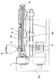
例えばセラミック材料等を混練する材料押出機として、スクリューの本数が1本の1軸型材料押出機と、2以上の複数軸型材料押出機とが知られている。更に使用目的に応じて様々の構造のものが一般に知られている。ここで、従来の1軸型材料押出機について図15により説明する。
【0003】
図15に示すように、横方向に支持されたシリンダ2の内部に1本のスクリュー3が装着されている。スクリュー3の一端は減速機1及びベルト30を介してモータ4と接続されて回転する。スクリュー3の他端は、通常は自由支持(フリー)となっている。
【0004】
図15においてホッパ5から供給された例えばセラミック等からなる流動性材料は、供給口6よりシリンダ2の中に入り、スクリュー3により移送されながら、ヒータ80で加熱、溶融され、更にシリンダ2とスクリュー3の間で混練された後、排出口8より排出される。また材料の温度制御を容易に行うために、空冷用ブロア45が設けられているが、空冷用ブロアはないこともある。
【0005】
【発明が解決しようとする課題】
ところが、処理しようとする材料により、カサ比重や溶融温度、粘性等の特性が異なる場合、安定した押出条件を保つために、加熱温度やスクリュー3の回転数を変更している。しかしながら、加熱温度やスクリュー3の回転数の変更のみでは十分対応できない場合があり、この場合は、材料の特性に合わせた形状の異なる複数のスクリュー3(たとえば異なる雄ねじを有するスクリュー)を用意して材料により交換しているのが実情である。
【0006】
本発明はこのような点を考慮してなされたものであり、特性の異なる材料に対しても安定した押出条件を達成して所望性状を有する処理材料を得ることができる材料押出機を提供することを目的とする。
【0007】
【課題を解決するための手段】
本発明は、供給口と排出口を有するシリンダと、シリンダ内に回転自在に配設され、外周に第1雄ねじを有する第1スクリューと、シリンダ内に第1スクリューと同軸に回転自在に配置され、外周に第2雄ねじを有する第2スクリューとを備え、第1スクリューと第2スクリューは、各々独立して駆動されることを特徴とする材料押出機である。
【0008】
また、第1スクリューと第2スクリューのうち少なくとも一方は、対応する駆動源により回転数または回転方向が可変となっていることを特徴としている。
【0009】
また、第1スクリューおよび第2スクリューのうち少なくとも一方の外面であって、第1雄ねじまたは第2雄ねじが形成されない領域に、複数の外周溝を設けたことを特徴としている。
【0010】
また、シリンダ内面に内周溝を設けたことを特徴としている。
【0011】
また、第1スクリューおよび第2スクリューのうち少なくとも一方の端部に、溝部を有する混練機構を設けたことを特徴としている。
【0012】
また、シリンダに内部ガスを脱気する脱気口を設けたことを特徴としている。
【0013】
また、シリンダに加熱機構または冷却機構のいずれかを設けたことを特徴としている。
【0014】
また、第1スクリューおよび第2スクリューのうち少なくとも一方に、加熱機構または冷却機構のいずれかを設けたことを特徴としている。
【0015】
また、シリンダ内のうち、第1スクリューと第2スクリューとの間に、絞り機構を設けたことを特徴としている。
【0016】
また、シリンダ内のうち、第1スクリューと第2スクリューとの間にフィルタ機構を設けたことを特徴としている。
【0017】
また、シリンダの排出口に、材料の形状を定めるダイ機構を設けたことを特徴としている。
【0018】
本発明によれば、供給口からシリンダ内に流動性材料が供給されると、シリンダ内において第1スクリューの第1雄ねじと第2スクリューの第2雄ねじにより材料が混練されながら移送される。第1スクリューおよび第2スクリューは各々の駆動源により、回転されるので、材料の性状、必要とされる混練の程度、処理量に応じた押出条件を容易に得ることができる。
【0019】
また第1スクリューおよび第2スクリューのうちいずれか一方は、回転数または、回転方向が、可変となっているので、材料の性状、必要とされる混練の程度、処理量により一層適した運転条件が得られる。また第1スクリューまたは第2スクリューの回転を逆回転にすることにより、移送中の材料を逆方向に戻すことが可能となり、移送中に不具合が生じた場合でも、装置を停止することなく、運転を継続することが可能となる。
【0020】
また、第1スクリューまたは第2スクリューに設けた外周溝により材料を分割しながらせん断力を与えることができ、混練の程度を高めることが可能となる。
【0021】
また、シリンダ内面に設けた内周溝により材料を乱流状態としながら材料にせん断力を与えることができ、混練の程度を高めることが可能となる。
【0022】
また、第1スクリューおよび第2スクリューの一方の端部に混練機構を設けることにより、材料に対してせん断力、こねる力、その他の力が加わり混練の程度を高めることが可能となる。
【0023】
また、シリンダに脱気口を設けたことにより、材料が混練される際に発生するガスを効果的に取外すことが可能となる。
【0024】
また、シリンダ側に加熱手段又は、冷却手段を設けているので、加熱の場合は、混練及び脱気の程度を高めることが可能となり、冷却の場合は、溶融物を所要の粘性、温度等にすることが可能となる。
【0025】
また、第1スクリューまたは第2スクリュー側に加熱手段又は冷却手段を設けているので、加熱の場合は混練及び脱気の程度を高めることが可能となり、冷却の場合は、溶融物を所要の粘性、温度等にすることが可能となる。
【0026】
また、シリンダ内の第1スクリューと第2スクリューとの間に絞り機構を設けることにより、材料の流れに抵抗が加わり、そのために、混練の効果を向上させることが可能となる。
【0027】
さらにまた、シリンダ内の第1スクリューと第2スクリューとの間にフィルタ機構を設けることにより材料中の異物が除去され、閉塞の生じない安定した運転が可能となる。
【0028】
また、排出口に設けられたダイ機構により所要の形状に成形された処理済材料を得ることが可能となる。
【0029】
【発明の実施の形態】
第1の実施の形態
以下、図面を参照して本発明の実施の形態について説明する。
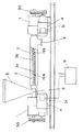
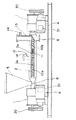
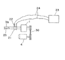
図1は本発明による材料押出機の第1の実施の形態を示す図である。図1に示すように、材料押出機は減速機1に水平方向に支持されるとともに供給口6と排出口8を有するシリンダ2と、シリンダ2内に回転自在に配設され外周に第1雄ねじ10aを有する第1スクリュー3aと、シリンダ2内に第1スクリュー3aと同軸に回転自在に配設され外周に第2雄ねじ10bを有する第2スクリュー3bとを備えている。
【0030】
図1において、第1雄ねじ10aと第2雄ねじ10bは逆方向に形成されているか、正方向に形成されていてもよい。また、シリンダ2は1本でもよく、また複数本でもよい。
【0031】
第1スクリュー3aおよび第2スクリュー3bは、分離独立しており、第1スクリュー3aおよび第2スクリュー3bは減速機1,1内部の伝達機構およびベルト30,30を介してモータ4,4に連結されている。また各モータ4,4には端子箱31,31が取付けられている。
【0032】
さらにシリンダ2の供給口6上方には、セラミック材料等からなる流動性材料が投入されるホッパ5が設けられている。またシリンダ2はシリンダカバー7により覆われている。
【0033】
次にこのような構成からなる本実施の形態の作用について説明する。
まずホッパ5に流動性材料が投入され、材料はその後、供給口6からシリンダ2内に供給される。シリンダ2内に供給された材料は、まず第1スクリュー3aの第1雄ねじ10aによって混練されながら移送され、次に第2スクリュー3bの第2雄ねじ10bによって混練されながら排出口8方向へ移送される。
【0034】
この場合、第1雄ねじ10aと第2雄ねじ10bとが逆方向に形成されていると、第1スクリュー3aと第2スクリュー3bの回転方向は逆向きとなる。
【0035】
シリンダ2内において、排出口8側へ移送した材料は、その後排出口8から排出される。
【0036】
本実施の形態によれば、シリンダ2内に第1スクリュー3aおよび第2スクリュー3bを別個独立して設けたので、例えば第1スクリュー3aを高速とし、第2スクリュー3bを低速にして第1スクリュー3aと第2スクリュー3bの回転数を異ならせることにより、シリンダ2内において材料の圧力を可変とすることができる。このため材料の特性に必要とされる混練の程度および処理等に応じて運転することができ、所望の処理済材料を得ることができる。
【0037】
第2の実施の形態
次に図2により本発明の第2の実施の形態について説明する。図2に示す第2の実施の形態は、各モータ4,4に制御装置9を設け、この制御装置9によって第1スクリュー3aおよび第2スクリュー3bの回転方向および回転数を可変としたものであり、他は図1に示す第1の実施の形態と略同一である。
【0038】
図2において、図1に示す第1の実施の形態と同一部分には同一符号を付して詳細な説明は省略する。
【0039】
図2において、第1スクリュー3aおよび第2スクリュー3bの回転数および回転方向は可変となっているので、シリンダ2内における材料の移送方向および圧力を所望に応じて可変とすることができる。このことにより、材料の特性に必要とされる運転条件をより確実に得ることができる。
【0040】
第3の実施の形態
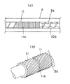
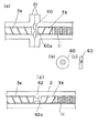
次に図3(a)(b)により本発明の第3の実施の形態について説明する。図3(a)(b)に示す第3の実施の形態は第2スクリュー3bの第1スクリュー3a側端部の外面であって、第2雄ねじ3bが形成されない領域に、複数の外周溝11を設けたものであり、他は図1に示す第1の実施の形態と略同一である。
【0041】
図3(a)(b)において、図1に示す第1の実施の形態と同一部分には同一符号を付して詳細な説明は省略する。
【0042】
ここで図3(a)は第2スクリュー3bを示す側面図、図3(b)は第2スクリュー3bを示す斜視図である。
【0043】
図3(a)(b)に示すように、第2スクリュー3bの外面に複数の外周溝11が形成されているので、まず第1スクリュー3aの雄ねじ10aに沿って移送された材料は、その後第2スクリュー3bの第2雄ねじ10b側へ移送される。第2雄ねじ10bにより一本のすじ状に送られた材料は、複数の外周溝11により複数のすじ状に分けられ、このように複数のすじ状に分けられる時に材料にせん断力が加えられ、材料が混練される。
【0044】
第2スクリュー3bに設けられた外周溝11は、例えば4段に分けて設けられ、各段の外周溝11間に外周溝11のない合流部11aが設けられている。多数の外周溝11によってせん断力が加えられた材料は、この合流部11aにおいて合流し、材料の混練がより進行する。
【0045】
なお、図3(a)(b)において、第2スクリュー3bの外面に複数の外周溝11を設けた例を示したが、これに限らず第1スクリュー3aの外面に設けてもよい。
【0046】
第4の実施の形態
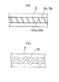
次に図4(a)(b)により本発明の第4の実施の形態について説明する。図4(a)(b)に示す第4の実施の形態は、シリンダ2の内面に内周溝12を設けたものであり、他は図1に示す第1の実施の形態と略同一である。
【0047】
図4(a)(b)において、図1に示す第1の実施の形態と同一部分には同一符号を付して詳細な説明は省略する。
【0048】
ここで図4(a)はシリンダ2内に設けられた第1スクリュー3aおよび第2スクリュー3bを示す側面図、図4(b)はシリンダ2内面を示す図である。
【0049】
図4(a)(b)において、シリンダ2内で第1スクリュー3aおよび第2スクリュー3bにより移送された材料は、シリンダ2の内面に形成された内周溝12内に入り、材料に乱流が生じる。このとき材料には、乱流によりせん断力が与えられて材料の混練が進行する。
【0050】
第5の実施の形態
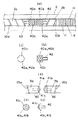
次に図5(a)(b)(c)(d)(e)(f)により、本発明の第5の実施の形態について説明する。図5(a)(b)(c)(d)(e)(f)に示す第5の実施の形態は、第2スクリュー3bの外面に複数の外周溝11を設けるとともに、第1スクリュー3aの端部および第2スクリュー3bの端部に混練機構40a,40bを各々設けたものである。他の構成は図1に示す第1の実施の形態と略同一である。
【0051】
図5(a)(b)(c)(d)(e)(f)において、図1に示す第1の実施の形態と同一部分には同一符号を付して詳細な説明は省略する。
【0052】
ここで図5(a)は混練機構40a,40bを有する第1スクリュー3aおよび第2スクリュー3bの側面図、図5(b)は図5(a)に示す混練機構40a,40bの側面図、図5(c)は図5(a)に示す混練機構40a,40bの正面図、図5(d)は変形例としての混練機構41a,41bを有する第1スクリュー3aおよび第2スクリュー3bの側面図、図5(e)は図5(d)に示す混練機構41a,41bの側面図、図5(f)は図5(d)に示す混練機構41a,41bの正面図である。
【0053】
図5(a)(b)(c)に示すように、第2スクリュー3bの外面に複数の外周溝11が設けられ、さらに第1スクリュー3aの端部および第2スクリュー3bの端部3bに円筒状の混練機構40a,40bが設けられている。混練機構40a,40bは、各々取付ねじ42,42を有し、この取付ねじ42,42により第1スクリュー3aの端部および第2スクリュー3bの端部に各々装着されている。
【0054】
混練機構40a,40bは、前述のように円筒状をなし、その外面に溝部40cが形成されている。
【0055】
図5(a)(b)(c)において、第1スクリュー3aにより移送されてきた材料は、例えば第1スクリュー3aと異なる回転数で回転する第2スクリュー3b側へ移行する。この間、第1スクリュー3aの端部と第2スクリュー3bの端部に、各々混練機構40a,40bが設けられているので、材料は各混練機構40a,40bの溝部40c内に入り、材料の分割が行なわれる。材料の分割が行なわれると材料にせん断力が加わり、このため材料の混練が進行する。
【0056】
なお、図5(a)(b)(c)に示す円筒状混練機構40a,40bの代わりに、第1スクリュー3aの端部および第2スクリュー3bの端部に図5(d)(e)(f)に示す円すい状混練機構41a,41bを取付ねじ42により装着してもよい。図5(a)(b)(c)において、円すい状混練機構41a,41bはその外面に溝部41aが形成されている。
【0057】
また、図5(a)(b)(c)および図5(d)(e)(f)において、第1スクリュー3aの端部および第2スクリュー3bの端部に、各々混練機構40a,40bまたは混練機構41a,41bを設けた例を示したが、第1スクリュー3aおよび第2スクリュー3bのうち、いずれか一方に設けてもよい。
【0058】
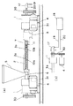
第6の実施の形態
次に図6により本発明の第6の実施の形態について説明する。
図6に示す第6の実施の形態は、シリンダ2の中央部近傍および排出口8近傍に、脱気口14を有する脱気室14を各々設けるとともに、第2スクリュー3bの外面に複数の外周溝11を設けたものである。他の構成は、図1に示す第1の実施の形態と略同一である。
【0059】
図6において、図1に示す第1の実施の形態と同一部分には同一符号を付して詳細な説明は省略する。
【0060】
図6において、シリンダ2の中央部近傍および排出口8近傍に脱気口14を有する脱気室13を設けたので、例えば材料が水分を含む場合、シリンダ2内において混練中に材料から水蒸気等のガスが生じても、このガスをシリンダ2の中央部近傍の脱気口14および排出口8近傍の脱気口14から外方へ排気することができる。
【0061】
なお、脱気口14を有する脱気室13を設ける代わりに、脱気ノズルを直接シリンダ2に設けてもよい。
【0062】
第7の実施の形態
次に図7および図8により本発明の第7の実施の形態について説明する。図7に示す実施の形態はシリンダ2を電気ヒータ50で加熱するとともに、第2スクリュー3bに複数の外周溝11を設けたものであり、他は図1に示す第1の実施の形態と略同一である。図7において、図1に示す第1の実施の形態と同一部分には同一符号を付して詳細な説明は省略する。
【0063】
図7に示すように、シリンダ2の外表面にシリンダ2を取囲むように電気ヒータ50が設置され、この電気ヒータ50には温度制御装置51が接続されている。また電気ヒータ50は複数のセグメントに分割され、このためきめ細かな温度制御が可能となっている。
【0064】
このようにシリンダ2を加熱することにより、材料を溶融させたり、材料からガスを容易に発生させることができる。
【0065】
なお、図7において、電気ヒータ50で加熱する例を示したが、これに限らずバーナでシリンダ2を加熱してもよく、熱媒で加熱してもよい。また複数の熱源の組合せ、例えば電気ヒータと熱媒を組み合わせてシリンダ2を加熱してもよい。
【0066】
また、シリンダ2を加熱する(図7)代わりに、図8に示すようにシリンダ2を冷却してもよい。すなわち、図8に示すようにシリンダ2の外表面にシリンダ2を取囲むようにジャケット52が設けられ、このジャケット52に冷却装置53により冷却された水が供給されてシリンダ2を冷却している。冷却源としては水の他、冷媒、空気などを用いてもよい。空気を用いる場合は、ブロアが設置される。
【0067】
図8において、シリンダ2を冷却することにより、材料に所定の粘性をもたせることができ、排出口8から所定粘性をもった処理済の材料を得ることができる。
【0068】
また図7に示す電気ヒータ50と、図8に示す冷却用ジャケット52とを組合せ、シリンダ2の上流側において電気ヒータ50により材料を加熱して材料中からガスを発生させるとともにシリンダ2の下流側において冷却ジャケット52により材料を冷却してもよい。
【0069】
第8の実施の形態
次に図9乃至11により本発明の第8の実施の形態について説明する。
図9乃至11に示す第8の実施の形態は、第2スクリュー3bを加熱または冷却するとともに、第2スクリュー3bの外面に複数の外周溝11を設けたものである。
【0070】
他の構成は、図1に示す第1の実施の形態と略同一である。図9乃至11において、図1に示す第1の実施の形態と同一部分には同一符号を付して詳細な説明は省略する。
【0071】
すなわち、図9に示すように、スクリュー側熱源18が配置され、スクリュー側熱源18から供給される高温流体が入口配管19およびロータリジョイント17を通って第2スクリュー3bに入り、第2スクリュー3bを加熱する。第2スクリュー3bの内部には循環路(図示せず)が形成されており、第2スクリュー3b内部の循環路を通過した高温流体は、ロータリジョイント17および出口配管20を通ってスクリュー側熱源18に戻る。
【0072】
このように第2スクリュー3bを加熱することにより、材料を溶融させたり、材料からガスを発生させることができる。
【0073】
なお、図9に示すようなスクリュー側熱源18を設ける代わりに、図10に示すように電気ヒータ25により第2スクリュー3bを加熱してもよい。
【0074】
すなわち、図10に示すように、第2スクリュー3bの内部に電気ヒータ25が設けられており、第2スクリュー3bの外周部にはスリップリング21が取付けられている。またスリップリング21にはブラシ22が接続されている。
【0075】
図10において、電源23より電線24、ブラシ22、およびスリップリング21を通って電気ヒータ25に電気が供給され、電気ヒータ25により第2スクリュー3bが加熱される。
【0076】
さらに図9および図10に示すように、第2スクリュー3bを加熱する代わりに、図11に示すように第2スクリュー3bを冷却してもよい。
【0077】
すなわち、図11に示すように、スクリュー側冷却源27が配置され、スクリュー側冷却源27から供給される冷却流体が入口配管28およびロータリジョイント26を通って第2スクリュー3bに入り第2スクリュー3bを冷却する。
【0078】
図示はしていないが、第2スクリュー3bの内部には循環路が形成されており、第2スクリュー3bの内部の循環路を通過した冷却流体はロータリジョイント26および出口配管29を通ってスクリュー側冷却源27に戻る。
【0079】
このように第2スクリュー3bを冷却することにより、材料に所定の粘性をもたせ、排出口8から所定粘性をもった処理済の材料を得ることができる。
【0080】
なお、図9乃至11において、第2スクリュー3bを加熱したり冷却した例を示したが、第2スクリュー3bの代わりにまたは第2スクリュー3bとともに第2スクリュー3aを加熱したり冷却してもよい。
【0081】
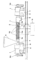
第9の実施の形態
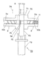
次に図12(a)(b)(c)(d)により本発明の第9の実施の形態について説明する。図12(a)(b)(c)(d)に示す第9の実施の形態は、シリンダ2内であって第1スクリュー3aと第2スクリュー3bとの間に絞り機構60,62を設けるとともに、第2スクリュー3bの外面に複数の外周溝11を設けたものである。他の構成は図1に示す第1の実施の形態と略同一である。
【0082】
図12(a)(b)(c)(d)において、図1に示す第1の実施の形態と同一部分には同一符号を付して詳細な説明は省略する。
【0083】
すなわち、図12(a)(b)(c)に示すように、シリンダ2内であって第1スクリュー3aと第2スクリュー3bとの間に開口60aを有する絞り機構60が設けられている。絞り機構60はシリンダ2に設けられたフランジ61により挟持されて保持されている。ここで図12(a)は絞り機構60の取付構造を示す側面図、図12(b)は絞り機構60の正面図、図12(c)は絞り機構60の断面図である。
【0084】
このように第1スクリュー3aと第2スクリュー3bとの間に絞り機構60を設けることにより、シリンダ2内の材料に圧力を加えて混練を進めることができる。また、第1スクリュー3aと第2スクリュー3bとの間に一定の空間が形成されている。第1スクリュー3aの第1雄ねじ10aによって形成された狭い流路を送る材料が第2スクリュー3bの第2雄ねじ10bによって形成された狭い流路へ移行するが、この場合第1スクリュー3aと第2スクリュー3bとの間の空間を絞り機構60により狭くしておくことにより、第1スクリュー3aから第2スクリュー3bへの材料の移行がスムースに行なわれる。
【0085】
なお、図12(a)(b)(c)に示すように、シリンダ2と別体に絞り機構60を設ける代わりに、シリンダ2に開口62aを有する絞り機構62を一体に設けてもよい。
【0086】
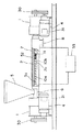
第10の実施の形態
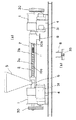
次に図13により本発明に第10の実施の形態について説明する。図13に示す第10の実施の形態は、シリンダ2のうち第1スクリュー3aと第2スクリュー3bとの間にフィルタ機構70を設けるとともに、第2スクリュー3bの外面に複数の外周溝11を設けたものである。他の構成は図1に示す第1の実施の形態と略同一である。
【0087】
図13において、図1に示す第1の実施の形態と同一部分には同一符号を付して詳細な説明は省略する。
【0088】
すなわち、図13に示すように、シリンダ2内であって第1スクリュー3aと第2スクリュー3bとの間にフィルタ機構70が設けられている。フィルタ機構70はハウジング72と、ハウジング72内に収納されたフィルタ74およびフィルタ支え75とを有しており、ハウジング72は保持体71内に摺動自在に保持されている。また保持体71内に保持されたハウジング72は駆動部73により駆動される。なお、保持体71はシリンダ2に取付けたれたフランジ76により挟持されて固定される。
【0089】
なおフィルタ支え75は、フィルタ74のその変形が生じないようにフィルタ74を保持するものである。
【0090】
図10はフィルタ74がシリンダ2内の流路上にあって材料中の異物除去を行っている状況を示している。フィルタ74に目詰りが生じた場合には、ハウジング72が駆動部73により保持体71内で摺動し、A点まで到達する。このようにしてフィルタ74をシリンダ2の外部に位置させ、フィルタ74を交換することができる。フィルタ74の交換が終了したら、再び駆動部73により、ハウジング72を保持体71内で摺動させて元の位置に戻す。
【0091】
なお、フィルタ機構70は1台に限らず、運転中にフィルタ74を交換するために、フィルタ機構70を2台設けてフィルタ74の交換中も他のフィルタ機構70のフィルタ74によって材料中の異物除去を行ってもよい。
【0092】
第2スクリュー3b外面に設けられた外周溝11は、その溝形状が細かいので異物が詰まり易いが、フィルタ機構70のフィルタ74により材料中の異物を取除くことによりフィルタ機構70より下流側の外周溝11内に異物が入ることはない。
【0093】
第11の実施の形態
次に図14(a)(b)により本発明の第11の実施の形態について説明する。図14(a)(b)に示す第11の実施の形態は排出口8に処理済材料の形状を定めるダイ機構35を設けるとともに、第2スクリュー3bの外面に複数の外周溝11を設けたものである。他の構成は図1に示す第1の実施の形態と略同一でである。
【0094】
図14(a)(b)において、図1に示す第1の実施の形態と同一部分には同一符号を付して詳細な説明は省略する。
【0095】
図14に示すように、シリンダ2の排出口8にダイ機構35が設けられている。ダイ機構35の形状を種々変えることにより、例えば細長状の処理済材料を得ることができる。この細長状材料を切断することにより、所望形状の塊状材料を得ることができる。
【0096】
【発明の効果】
以上説明したように、本発明によれば、処理すべき材料の性状が異なっても、1台の材料押出機により容易に適切な押出条件を達成することができる。このため所望性状の処理材料を得ることができる。
【図面の簡単な説明】
【図1】本発明による材料押出機の第1の実施の形態を示す構成図。
【図2】本発明による材料押出機の第2の実施の形態を示す構成図。
【図3】本発明による材料押出機の第3の実施の形態を示す構成図。
【図4】本発明による材料押出機の第4の実施の形態を示す構成図。
【図5】本発明による材料押出機の第5の実施の形態を示す構成図。
【図6】本発明による材料押出機の第6の実施の形態を示す構成図。
【図7】本発明による材料押出機の第7の実施の形態を示す構成図。
【図8】本発明による材料押出機の第7の実施の形態の変形例を示す構成図。
【図9】本発明による材料押出機の第8の実施の形態を示す構成図。
【図10】本発明による材料押出機の第8の実施の形態の変形例を示す構成図。
【図11】本発明による材料押出機の第8の実施の形態の変形例を示す構成図。
【図12】本発明による材料押出機の第9の実施の形態を示す構成図。
【図13】本発明による材料押出機の第10の実施の形態を示す構成図。
【図14】本発明による材料押出機の第11の実施の形態を示す構成図。
【図15】従来の材料押出機を示す構成図。
【符号の説明】
2 シリンダ
3a 第1スクリュー
3b 第2スクリュー
4 モータ
5 ホッパ
6 供給口
8 排出口
9 制御装置
10a 第1雄ねじ
10b 第2雄ねじ
11 外周溝
12 内周溝
13 脱気室
14 脱気口
18 スクリュー側熱源
25 電気ヒータ
27 スクリュー側冷却源
35 ダイ機構
40a,40b,41a,41b 混練機構
40c,41c 溝部
50 電気ヒータ
52 冷却用ジャケット
60,62 絞り機構
70 フィルタ機構[0001]
BACKGROUND OF THE INVENTION
The present invention relates to a material extruder that kneads a fluid material made of, for example, a ceramic material and performs deaeration as necessary.
[0002]
[Prior art]
For example, as a material extruder for kneading a ceramic material or the like, a single-screw material extruder having one screw and two or more multi-shaft material extruders are known. Further, various structures are generally known depending on the purpose of use. Here, a conventional single-screw material extruder will be described with reference to FIG.
[0003]
As shown in FIG. 15, one
[0004]
In FIG. 15, the fluid material made of ceramic or the like supplied from the
[0005]
[Problems to be solved by the invention]
However, when characteristics such as bulk specific gravity, melting temperature, and viscosity differ depending on the material to be processed, the heating temperature and the rotational speed of the
[0006]
The present invention has been made in consideration of the above points, and provides a material extruder capable of obtaining a processing material having desired properties by achieving stable extrusion conditions even for materials having different characteristics. For the purpose.
[0007]
[Means for Solving the Problems]
The present invention includes a cylinder having a supply port and a discharge port, a first screw that is rotatably disposed in the cylinder and having a first male screw on the outer periphery, and a cylinder that is rotatable coaxially with the first screw. The material extruder includes a second screw having a second male screw on the outer periphery, and the first screw and the second screw are independently driven.
[0008]
In addition, at least one of the first screw and the second screw is characterized in that the number of rotations or the direction of rotation is variable by a corresponding drive source.
[0009]
In addition, a plurality of outer peripheral grooves are provided on an outer surface of at least one of the first screw and the second screw and in a region where the first male screw or the second male screw is not formed.
[0010]
Further, an inner peripheral groove is provided on the inner surface of the cylinder.
[0011]
In addition, a kneading mechanism having a groove is provided at at least one end of the first screw and the second screw.
[0012]
Further, the cylinder is provided with a degassing port for degassing the internal gas.
[0013]
In addition, the cylinder is provided with either a heating mechanism or a cooling mechanism.
[0014]
Further, at least one of the first screw and the second screw is provided with either a heating mechanism or a cooling mechanism.
[0015]
Further, the present invention is characterized in that a throttle mechanism is provided between the first screw and the second screw in the cylinder.
[0016]
Further, a filter mechanism is provided between the first screw and the second screw in the cylinder.
[0017]
In addition, a die mechanism for determining the shape of the material is provided at the discharge port of the cylinder.
[0018]
According to the present invention, when the flowable material is supplied into the cylinder from the supply port, the material is transferred in the cylinder while being kneaded by the first male screw of the first screw and the second male screw of the second screw. Since the first screw and the second screw are rotated by respective drive sources, extrusion conditions corresponding to the properties of the material, the required degree of kneading, and the throughput can be easily obtained.
[0019]
In addition, since either the first screw or the second screw has a variable rotation speed or rotation direction, the operating conditions are more suitable for the properties of the material, the degree of kneading required, and the throughput. Is obtained. In addition, by reversing the rotation of the first screw or the second screw, it becomes possible to return the material being transferred in the reverse direction, and even if a malfunction occurs during the transfer, the operation can be performed without stopping the device. Can be continued.
[0020]
Further, a shear force can be applied while dividing the material by the outer peripheral groove provided in the first screw or the second screw, and the degree of kneading can be increased.
[0021]
Further, the inner circumferential groove provided on the inner surface of the cylinder can impart a shearing force to the material while keeping the material in a turbulent state, thereby increasing the degree of kneading.
[0022]
Further, by providing a kneading mechanism at one end of the first screw and the second screw, it becomes possible to increase the degree of kneading by applying shearing force, kneading force and other forces to the material.
[0023]
Further, by providing a deaeration port in the cylinder, it is possible to effectively remove the gas generated when the material is kneaded.
[0024]
In addition, since heating means or cooling means are provided on the cylinder side, it is possible to increase the degree of kneading and degassing in the case of heating, and in the case of cooling, the melt is brought to the required viscosity, temperature, etc. It becomes possible to do.
[0025]
In addition, since the heating means or the cooling means is provided on the first screw or the second screw side, it is possible to increase the degree of kneading and degassing in the case of heating, and in the case of cooling, the melt is made to have the required viscosity. , Temperature, etc. can be achieved.
[0026]
Further, by providing a throttling mechanism between the first screw and the second screw in the cylinder, resistance is added to the flow of the material, and therefore the kneading effect can be improved.
[0027]
Furthermore, by providing a filter mechanism between the first screw and the second screw in the cylinder, foreign substances in the material are removed, and a stable operation without blocking is possible.
[0028]
Moreover, it becomes possible to obtain the processed material shape | molded by required shape with the die mechanism provided in the discharge port.
[0029]
DETAILED DESCRIPTION OF THE INVENTION
First embodiment
Embodiments of the present invention will be described below with reference to the drawings.
FIG. 1 is a view showing a first embodiment of a material extruder according to the present invention. As shown in FIG. 1, the material extruder is supported horizontally by the
[0030]
In FIG. 1, the first
[0031]
The first screw 3a and the
[0032]
Further, a
[0033]
Next, the operation of the present embodiment having such a configuration will be described.
First, a flowable material is introduced into the
[0034]
In this case, if the first
[0035]
In the
[0036]
According to the present embodiment, since the first screw 3a and the
[0037]
Second embodiment
Next, a second embodiment of the present invention will be described with reference to FIG. In the second embodiment shown in FIG. 2, a
[0038]
In FIG. 2, the same parts as those of the first embodiment shown in FIG.
[0039]
In FIG. 2, since the rotation speed and rotation direction of the first screw 3a and the
[0040]
Third embodiment
Next, a third embodiment of the present invention will be described with reference to FIGS. In the third embodiment shown in FIGS. 3A and 3B, a plurality of outer
[0041]
3A and 3B, the same parts as those of the first embodiment shown in FIG.
[0042]
3A is a side view showing the
[0043]
As shown in FIGS. 3 (a) and 3 (b), since a plurality of outer
[0044]
The outer
[0045]
3A and 3B, an example in which the plurality of outer
[0046]
Fourth embodiment
Next, a fourth embodiment of the present invention will be described with reference to FIGS. The fourth embodiment shown in FIGS. 4 (a) and 4 (b) is provided with an inner
[0047]
4 (a) and 4 (b), the same parts as those of the first embodiment shown in FIG.
[0048]
4A is a side view showing the first screw 3a and the
[0049]
4 (a) and 4 (b), the material transferred by the first screw 3a and the
[0050]
Fifth embodiment
Next, a fifth embodiment of the present invention will be described with reference to FIGS. 5 (a), (b), (c), (d), (e), and (f). In the fifth embodiment shown in FIGS. 5A, 5B, 5C, 5D, 5E, and 5F, a plurality of outer
[0051]
5 (a), (b), (c), (d), (e), and (f), the same parts as those in the first embodiment shown in FIG.
[0052]
5A is a side view of the first screw 3a and the
[0053]
As shown in FIGS. 5A, 5B, and 5C, a plurality of outer
[0054]
The kneading
[0055]
5A, 5B, and 5C, the material transferred by the first screw 3a moves to the
[0056]
In addition, instead of the
[0057]
5 (a), (b), (c) and FIGS. 5 (d), (e), and (f), kneading
[0058]
Sixth embodiment
Next, a sixth embodiment of the present invention will be described with reference to FIG.
In the sixth embodiment shown in FIG. 6, a
[0059]
In FIG. 6, the same parts as those of the first embodiment shown in FIG.
[0060]
In FIG. 6, since the
[0061]
Instead of providing the
[0062]
Seventh embodiment
Next, a seventh embodiment of the present invention will be described with reference to FIGS. In the embodiment shown in FIG. 7, the
[0063]
As shown in FIG. 7, an
[0064]
By heating the
[0065]
In addition, although the example heated with the
[0066]
Further, instead of heating the cylinder 2 (FIG. 7), the
[0067]
In FIG. 8, by cooling the
[0068]
Further, the
[0069]
Eighth embodiment
Next, an eighth embodiment of the present invention will be described with reference to FIGS.
In the eighth embodiment shown in FIGS. 9 to 11, the
[0070]
Other configurations are substantially the same as those of the first embodiment shown in FIG. 9 to 11, the same parts as those of the first embodiment shown in FIG.
[0071]
That is, as shown in FIG. 9, the screw-
[0072]
By heating the
[0073]
Instead of providing the screw
[0074]
That is, as shown in FIG. 10, the
[0075]
In FIG. 10, electricity is supplied from the
[0076]
Further, as shown in FIGS. 9 and 10, instead of heating the
[0077]
That is, as shown in FIG. 11, the screw
[0078]
Although not shown, a circulation path is formed inside the
[0079]
By cooling the
[0080]
9 to 11 show an example in which the
[0081]
Ninth embodiment
Next, a ninth embodiment of the present invention will be described with reference to FIGS. 12 (a), (b), (c), and (d). In the ninth embodiment shown in FIGS. 12A, 12B, 12C, and 12D,
[0082]
12A, 12B, 12C, and 12D, the same parts as those in the first embodiment shown in FIG.
[0083]
That is, as shown in FIGS. 12A, 12B, and 12C, a
[0084]
Thus, by providing the
[0085]
12A, 12B, and 12C, instead of providing the
[0086]
Tenth embodiment
Next, a tenth embodiment of the present invention will be described with reference to FIG. In the tenth embodiment shown in FIG. 13, a
[0087]
In FIG. 13, the same parts as those of the first embodiment shown in FIG.
[0088]
That is, as shown in FIG. 13, a
[0089]
The
[0090]
FIG. 10 shows a situation where the
[0091]
Note that the number of
[0092]
The outer
[0093]
Eleventh embodiment
Next, an eleventh embodiment of the present invention will be described with reference to FIGS. In the eleventh embodiment shown in FIGS. 14 (a) and 14 (b), a
[0094]
14 (a) and 14 (b), the same parts as those of the first embodiment shown in FIG.
[0095]
As shown in FIG. 14, a
[0096]
【The invention's effect】
As described above, according to the present invention, even if the properties of the materials to be processed are different, appropriate extrusion conditions can be easily achieved by a single material extruder. For this reason, the processing material of a desired property can be obtained.
[Brief description of the drawings]
FIG. 1 is a configuration diagram showing a first embodiment of a material extruder according to the present invention.
FIG. 2 is a configuration diagram showing a second embodiment of a material extruder according to the present invention.
FIG. 3 is a configuration diagram showing a third embodiment of a material extruder according to the present invention.
FIG. 4 is a configuration diagram showing a fourth embodiment of a material extruder according to the present invention.
FIG. 5 is a configuration diagram showing a fifth embodiment of a material extruder according to the present invention.
FIG. 6 is a configuration diagram showing a sixth embodiment of a material extruder according to the present invention.
FIG. 7 is a configuration diagram showing a seventh embodiment of a material extruder according to the present invention.
FIG. 8 is a configuration diagram showing a modification of the seventh embodiment of the material extruder according to the present invention.
FIG. 9 is a configuration diagram showing an eighth embodiment of a material extruder according to the present invention.
FIG. 10 is a configuration diagram showing a modification of the eighth embodiment of the material extruder according to the present invention.
FIG. 11 is a configuration diagram showing a modification of the eighth embodiment of the material extruder according to the present invention.
FIG. 12 is a configuration diagram showing a ninth embodiment of a material extruder according to the present invention.
FIG. 13 is a configuration diagram showing a tenth embodiment of a material extruder according to the present invention.
FIG. 14 is a configuration diagram showing an eleventh embodiment of a material extruder according to the present invention.
FIG. 15 is a configuration diagram showing a conventional material extruder.
[Explanation of symbols]
2 cylinders
3a 1st screw
3b Second screw
4 Motor
5 Hoppers
6 Supply port
8 outlet
9 Control device
10a First male screw
10b Second male screw
11 peripheral groove
12 Inner circumferential groove
13 Degassing chamber
14 Degassing mouth
18 Screw side heat source
25 Electric heater
27 Screw side cooling source
35 die mechanism
40a, 40b, 41a, 41b kneading mechanism
40c, 41c groove
50 Electric heater
52 Cooling jacket
60, 62 Aperture mechanism
70 Filter mechanism
Claims (11)
シリンダ内に回転自在に配設され、外周に第1雄ねじを有する第1スクリューと、
シリンダ内に第1スクリューと同軸に回転自在に配置され、外周に第2雄ねじを有する第2スクリューとを備え、
第1スクリューと第2スクリューは、各々独立して駆動されることを特徴とする材料押出機。A cylinder having a supply port and a discharge port;
A first screw rotatably disposed within the cylinder and having a first male screw on the outer periphery;
A second screw having a second male screw disposed on the outer periphery thereof, and being rotatably disposed coaxially with the first screw in the cylinder;
The material extruder according to claim 1, wherein the first screw and the second screw are independently driven.
Priority Applications (1)
| Application Number | Priority Date | Filing Date | Title |
|---|---|---|---|
| JP02127798A JP3868614B2 (en) | 1998-02-02 | 1998-02-02 | Material extruder |
Applications Claiming Priority (1)
| Application Number | Priority Date | Filing Date | Title |
|---|---|---|---|
| JP02127798A JP3868614B2 (en) | 1998-02-02 | 1998-02-02 | Material extruder |
Publications (2)
| Publication Number | Publication Date |
|---|---|
| JPH11216353A JPH11216353A (en) | 1999-08-10 |
| JP3868614B2 true JP3868614B2 (en) | 2007-01-17 |
Family
ID=12050646
Family Applications (1)
| Application Number | Title | Priority Date | Filing Date |
|---|---|---|---|
| JP02127798A Expired - Fee Related JP3868614B2 (en) | 1998-02-02 | 1998-02-02 | Material extruder |
Country Status (1)
| Country | Link |
|---|---|
| JP (1) | JP3868614B2 (en) |
Families Citing this family (5)
| Publication number | Priority date | Publication date | Assignee | Title |
|---|---|---|---|---|
| JP4670173B2 (en) * | 2000-05-12 | 2011-04-13 | 株式会社デンソー | Extrusion equipment |
| JP5647707B2 (en) * | 2013-03-22 | 2015-01-07 | 株式会社日本製鋼所 | Continuous extrusion method and apparatus using twin screw extruder |
| CN103802195B (en) * | 2014-03-03 | 2016-04-13 | 汤凯全 | The method of attachment of light partition wall block forming machine and partition block and this partition block |
| JP7034422B2 (en) * | 2018-02-13 | 2022-03-14 | 株式会社日本製鋼所 | Two-screw extruder, reducer and extrusion method |
| CN116945543A (en) * | 2023-08-14 | 2023-10-27 | 江苏博云塑业股份有限公司 | Rectifying device installed in screw extruder and screw extruder |
-
1998
- 1998-02-02 JP JP02127798A patent/JP3868614B2/en not_active Expired - Fee Related
Also Published As
| Publication number | Publication date |
|---|---|
| JPH11216353A (en) | 1999-08-10 |
Similar Documents
| Publication | Publication Date | Title |
|---|---|---|
| JP4024976B2 (en) | Closed kneader | |
| KR101407878B1 (en) | Multi-screw extruder | |
| BRPI0409615B1 (en) | PROCESS FOR MELTING MULTIMODAL OR BIMODAL POLYLEPHINS | |
| JP3868614B2 (en) | Material extruder | |
| JP3803457B2 (en) | Biaxial continuous kneading extrusion equipment | |
| JPH1080943A (en) | Extruder for plastic granule | |
| JP5112002B2 (en) | Method and apparatus for homogenizing and filtering viscoelastic materials | |
| CN112074386B (en) | Extrusion molding machine and method for producing molded body | |
| US3719350A (en) | Self-cleaning venting section for continuous mixers | |
| JP2000309017A (en) | Different direction rotating twin screw type extruder | |
| CN1120251C (en) | Extrusion pump | |
| US12459185B2 (en) | Screw machine with a rotatable filter in a deaeration port | |
| CA2094985A1 (en) | Screw element having shearing and scraping flights | |
| US20050048156A1 (en) | Extruder | |
| US5297864A (en) | Degassing means for a twin screw extruder for plastic materials | |
| JPH0631725A (en) | Four-screw extruder | |
| JP7058542B2 (en) | Extruder and kneading extrusion method | |
| JP2006503725A (en) | Mixing equipment | |
| TW202426245A (en) | Conveying device and heating device | |
| US3310835A (en) | Disc extruder | |
| CN120418062A (en) | Extrusion device and method for kneading resin raw material | |
| US20240208106A1 (en) | Granulator, kneading adjustment mechanism, and method of manufacturing resin pellets | |
| JP2001121532A (en) | Continuous kneading machine | |
| JP4813826B2 (en) | Biaxial feeder, sheeting apparatus and kneading system using the same | |
| JP2021084294A (en) | Powder melting kneader |
Legal Events
| Date | Code | Title | Description |
|---|---|---|---|
| TRDD | Decision of grant or rejection written | ||
| A01 | Written decision to grant a patent or to grant a registration (utility model) |
Free format text: JAPANESE INTERMEDIATE CODE: A01 Effective date: 20061003 |
|
| A61 | First payment of annual fees (during grant procedure) |
Free format text: JAPANESE INTERMEDIATE CODE: A61 Effective date: 20061011 |
|
| R150 | Certificate of patent or registration of utility model |
Free format text: JAPANESE INTERMEDIATE CODE: R150 |
|
| FPAY | Renewal fee payment (event date is renewal date of database) |
Free format text: PAYMENT UNTIL: 20101020 Year of fee payment: 4 |
|
| FPAY | Renewal fee payment (event date is renewal date of database) |
Free format text: PAYMENT UNTIL: 20111020 Year of fee payment: 5 |
|
| FPAY | Renewal fee payment (event date is renewal date of database) |
Free format text: PAYMENT UNTIL: 20111020 Year of fee payment: 5 |
|
| FPAY | Renewal fee payment (event date is renewal date of database) |
Free format text: PAYMENT UNTIL: 20121020 Year of fee payment: 6 |
|
| FPAY | Renewal fee payment (event date is renewal date of database) |
Free format text: PAYMENT UNTIL: 20131020 Year of fee payment: 7 |
|
| LAPS | Cancellation because of no payment of annual fees |