JP3866732B2 - Laser bonding method for resin structures - Google Patents
Laser bonding method for resin structures Download PDFInfo
- Publication number
- JP3866732B2 JP3866732B2 JP2004127963A JP2004127963A JP3866732B2 JP 3866732 B2 JP3866732 B2 JP 3866732B2 JP 2004127963 A JP2004127963 A JP 2004127963A JP 2004127963 A JP2004127963 A JP 2004127963A JP 3866732 B2 JP3866732 B2 JP 3866732B2
- Authority
- JP
- Japan
- Prior art keywords
- laser beam
- region
- contact surface
- laser
- resin
- Prior art date
- Legal status (The legal status is an assumption and is not a legal conclusion. Google has not performed a legal analysis and makes no representation as to the accuracy of the status listed.)
- Expired - Fee Related
Links
Images


Classifications
-
- B—PERFORMING OPERATIONS; TRANSPORTING
- B29—WORKING OF PLASTICS; WORKING OF SUBSTANCES IN A PLASTIC STATE IN GENERAL
- B29C—SHAPING OR JOINING OF PLASTICS; SHAPING OF MATERIAL IN A PLASTIC STATE, NOT OTHERWISE PROVIDED FOR; AFTER-TREATMENT OF THE SHAPED PRODUCTS, e.g. REPAIRING
- B29C65/00—Joining or sealing of preformed parts, e.g. welding of plastics materials; Apparatus therefor
- B29C65/02—Joining or sealing of preformed parts, e.g. welding of plastics materials; Apparatus therefor by heating, with or without pressure
- B29C65/14—Joining or sealing of preformed parts, e.g. welding of plastics materials; Apparatus therefor by heating, with or without pressure using wave energy, i.e. electromagnetic radiation, or particle radiation
- B29C65/16—Laser beams
- B29C65/1629—Laser beams characterised by the way of heating the interface
- B29C65/1674—Laser beams characterised by the way of heating the interface making use of laser diodes
-
- B—PERFORMING OPERATIONS; TRANSPORTING
- B23—MACHINE TOOLS; METAL-WORKING NOT OTHERWISE PROVIDED FOR
- B23K—SOLDERING OR UNSOLDERING; WELDING; CLADDING OR PLATING BY SOLDERING OR WELDING; CUTTING BY APPLYING HEAT LOCALLY, e.g. FLAME CUTTING; WORKING BY LASER BEAM
- B23K26/00—Working by laser beam, e.g. welding, cutting or boring
- B23K26/02—Positioning or observing the workpiece, e.g. with respect to the point of impact; Aligning, aiming or focusing the laser beam
- B23K26/06—Shaping the laser beam, e.g. by masks or multi-focusing
- B23K26/064—Shaping the laser beam, e.g. by masks or multi-focusing by means of optical elements, e.g. lenses, mirrors or prisms
- B23K26/066—Shaping the laser beam, e.g. by masks or multi-focusing by means of optical elements, e.g. lenses, mirrors or prisms by using masks
-
- B—PERFORMING OPERATIONS; TRANSPORTING
- B29—WORKING OF PLASTICS; WORKING OF SUBSTANCES IN A PLASTIC STATE IN GENERAL
- B29C—SHAPING OR JOINING OF PLASTICS; SHAPING OF MATERIAL IN A PLASTIC STATE, NOT OTHERWISE PROVIDED FOR; AFTER-TREATMENT OF THE SHAPED PRODUCTS, e.g. REPAIRING
- B29C65/00—Joining or sealing of preformed parts, e.g. welding of plastics materials; Apparatus therefor
- B29C65/02—Joining or sealing of preformed parts, e.g. welding of plastics materials; Apparatus therefor by heating, with or without pressure
- B29C65/14—Joining or sealing of preformed parts, e.g. welding of plastics materials; Apparatus therefor by heating, with or without pressure using wave energy, i.e. electromagnetic radiation, or particle radiation
- B29C65/16—Laser beams
- B29C65/1629—Laser beams characterised by the way of heating the interface
- B29C65/1635—Laser beams characterised by the way of heating the interface at least passing through one of the parts to be joined, i.e. laser transmission welding
- B29C65/1638—Laser beams characterised by the way of heating the interface at least passing through one of the parts to be joined, i.e. laser transmission welding focusing the laser beam on the interface
-
- B—PERFORMING OPERATIONS; TRANSPORTING
- B29—WORKING OF PLASTICS; WORKING OF SUBSTANCES IN A PLASTIC STATE IN GENERAL
- B29C—SHAPING OR JOINING OF PLASTICS; SHAPING OF MATERIAL IN A PLASTIC STATE, NOT OTHERWISE PROVIDED FOR; AFTER-TREATMENT OF THE SHAPED PRODUCTS, e.g. REPAIRING
- B29C65/00—Joining or sealing of preformed parts, e.g. welding of plastics materials; Apparatus therefor
- B29C65/02—Joining or sealing of preformed parts, e.g. welding of plastics materials; Apparatus therefor by heating, with or without pressure
- B29C65/14—Joining or sealing of preformed parts, e.g. welding of plastics materials; Apparatus therefor by heating, with or without pressure using wave energy, i.e. electromagnetic radiation, or particle radiation
- B29C65/16—Laser beams
- B29C65/1629—Laser beams characterised by the way of heating the interface
- B29C65/1654—Laser beams characterised by the way of heating the interface scanning at least one of the parts to be joined
-
- B—PERFORMING OPERATIONS; TRANSPORTING
- B29—WORKING OF PLASTICS; WORKING OF SUBSTANCES IN A PLASTIC STATE IN GENERAL
- B29C—SHAPING OR JOINING OF PLASTICS; SHAPING OF MATERIAL IN A PLASTIC STATE, NOT OTHERWISE PROVIDED FOR; AFTER-TREATMENT OF THE SHAPED PRODUCTS, e.g. REPAIRING
- B29C66/00—General aspects of processes or apparatus for joining preformed parts
- B29C66/70—General aspects of processes or apparatus for joining preformed parts characterised by the composition, physical properties or the structure of the material of the parts to be joined; Joining with non-plastics material
- B29C66/71—General aspects of processes or apparatus for joining preformed parts characterised by the composition, physical properties or the structure of the material of the parts to be joined; Joining with non-plastics material characterised by the composition of the plastics material of the parts to be joined
- B29C66/712—General aspects of processes or apparatus for joining preformed parts characterised by the composition, physical properties or the structure of the material of the parts to be joined; Joining with non-plastics material characterised by the composition of the plastics material of the parts to be joined the composition of one of the parts to be joined being different from the composition of the other part
-
- B—PERFORMING OPERATIONS; TRANSPORTING
- B29—WORKING OF PLASTICS; WORKING OF SUBSTANCES IN A PLASTIC STATE IN GENERAL
- B29C—SHAPING OR JOINING OF PLASTICS; SHAPING OF MATERIAL IN A PLASTIC STATE, NOT OTHERWISE PROVIDED FOR; AFTER-TREATMENT OF THE SHAPED PRODUCTS, e.g. REPAIRING
- B29C66/00—General aspects of processes or apparatus for joining preformed parts
- B29C66/70—General aspects of processes or apparatus for joining preformed parts characterised by the composition, physical properties or the structure of the material of the parts to be joined; Joining with non-plastics material
- B29C66/73—General aspects of processes or apparatus for joining preformed parts characterised by the composition, physical properties or the structure of the material of the parts to be joined; Joining with non-plastics material characterised by the intensive physical properties of the material of the parts to be joined, by the optical properties of the material of the parts to be joined, by the extensive physical properties of the parts to be joined, by the state of the material of the parts to be joined or by the material of the parts to be joined being a thermoplastic or a thermoset
- B29C66/739—General aspects of processes or apparatus for joining preformed parts characterised by the composition, physical properties or the structure of the material of the parts to be joined; Joining with non-plastics material characterised by the intensive physical properties of the material of the parts to be joined, by the optical properties of the material of the parts to be joined, by the extensive physical properties of the parts to be joined, by the state of the material of the parts to be joined or by the material of the parts to be joined being a thermoplastic or a thermoset characterised by the material of the parts to be joined being a thermoplastic or a thermoset
- B29C66/7392—General aspects of processes or apparatus for joining preformed parts characterised by the composition, physical properties or the structure of the material of the parts to be joined; Joining with non-plastics material characterised by the intensive physical properties of the material of the parts to be joined, by the optical properties of the material of the parts to be joined, by the extensive physical properties of the parts to be joined, by the state of the material of the parts to be joined or by the material of the parts to be joined being a thermoplastic or a thermoset characterised by the material of the parts to be joined being a thermoplastic or a thermoset characterised by the material of at least one of the parts being a thermoplastic
- B29C66/73921—General aspects of processes or apparatus for joining preformed parts characterised by the composition, physical properties or the structure of the material of the parts to be joined; Joining with non-plastics material characterised by the intensive physical properties of the material of the parts to be joined, by the optical properties of the material of the parts to be joined, by the extensive physical properties of the parts to be joined, by the state of the material of the parts to be joined or by the material of the parts to be joined being a thermoplastic or a thermoset characterised by the material of the parts to be joined being a thermoplastic or a thermoset characterised by the material of at least one of the parts being a thermoplastic characterised by the materials of both parts being thermoplastics
-
- B—PERFORMING OPERATIONS; TRANSPORTING
- B29—WORKING OF PLASTICS; WORKING OF SUBSTANCES IN A PLASTIC STATE IN GENERAL
- B29C—SHAPING OR JOINING OF PLASTICS; SHAPING OF MATERIAL IN A PLASTIC STATE, NOT OTHERWISE PROVIDED FOR; AFTER-TREATMENT OF THE SHAPED PRODUCTS, e.g. REPAIRING
- B29C66/00—General aspects of processes or apparatus for joining preformed parts
- B29C66/80—General aspects of machine operations or constructions and parts thereof
- B29C66/83—General aspects of machine operations or constructions and parts thereof characterised by the movement of the joining or pressing tools
- B29C66/836—Moving relative to and tangentially to the parts to be joined, e.g. transversely to the displacement of the parts to be joined, e.g. using a X-Y table
-
- B—PERFORMING OPERATIONS; TRANSPORTING
- B29—WORKING OF PLASTICS; WORKING OF SUBSTANCES IN A PLASTIC STATE IN GENERAL
- B29C—SHAPING OR JOINING OF PLASTICS; SHAPING OF MATERIAL IN A PLASTIC STATE, NOT OTHERWISE PROVIDED FOR; AFTER-TREATMENT OF THE SHAPED PRODUCTS, e.g. REPAIRING
- B29C65/00—Joining or sealing of preformed parts, e.g. welding of plastics materials; Apparatus therefor
- B29C65/02—Joining or sealing of preformed parts, e.g. welding of plastics materials; Apparatus therefor by heating, with or without pressure
- B29C65/14—Joining or sealing of preformed parts, e.g. welding of plastics materials; Apparatus therefor by heating, with or without pressure using wave energy, i.e. electromagnetic radiation, or particle radiation
- B29C65/16—Laser beams
- B29C65/1687—Laser beams making use of light guides
-
- B—PERFORMING OPERATIONS; TRANSPORTING
- B29—WORKING OF PLASTICS; WORKING OF SUBSTANCES IN A PLASTIC STATE IN GENERAL
- B29C—SHAPING OR JOINING OF PLASTICS; SHAPING OF MATERIAL IN A PLASTIC STATE, NOT OTHERWISE PROVIDED FOR; AFTER-TREATMENT OF THE SHAPED PRODUCTS, e.g. REPAIRING
- B29C65/00—Joining or sealing of preformed parts, e.g. welding of plastics materials; Apparatus therefor
- B29C65/02—Joining or sealing of preformed parts, e.g. welding of plastics materials; Apparatus therefor by heating, with or without pressure
- B29C65/14—Joining or sealing of preformed parts, e.g. welding of plastics materials; Apparatus therefor by heating, with or without pressure using wave energy, i.e. electromagnetic radiation, or particle radiation
- B29C65/16—Laser beams
- B29C65/1696—Laser beams making use of masks
-
- B—PERFORMING OPERATIONS; TRANSPORTING
- B29—WORKING OF PLASTICS; WORKING OF SUBSTANCES IN A PLASTIC STATE IN GENERAL
- B29C—SHAPING OR JOINING OF PLASTICS; SHAPING OF MATERIAL IN A PLASTIC STATE, NOT OTHERWISE PROVIDED FOR; AFTER-TREATMENT OF THE SHAPED PRODUCTS, e.g. REPAIRING
- B29C66/00—General aspects of processes or apparatus for joining preformed parts
- B29C66/01—General aspects dealing with the joint area or with the area to be joined
- B29C66/05—Particular design of joint configurations
- B29C66/10—Particular design of joint configurations particular design of the joint cross-sections
- B29C66/11—Joint cross-sections comprising a single joint-segment, i.e. one of the parts to be joined comprising a single joint-segment in the joint cross-section
- B29C66/112—Single lapped joints
- B29C66/1122—Single lap to lap joints, i.e. overlap joints
-
- B—PERFORMING OPERATIONS; TRANSPORTING
- B29—WORKING OF PLASTICS; WORKING OF SUBSTANCES IN A PLASTIC STATE IN GENERAL
- B29C—SHAPING OR JOINING OF PLASTICS; SHAPING OF MATERIAL IN A PLASTIC STATE, NOT OTHERWISE PROVIDED FOR; AFTER-TREATMENT OF THE SHAPED PRODUCTS, e.g. REPAIRING
- B29C66/00—General aspects of processes or apparatus for joining preformed parts
- B29C66/40—General aspects of joining substantially flat articles, e.g. plates, sheets or web-like materials; Making flat seams in tubular or hollow articles; Joining single elements to substantially flat surfaces
- B29C66/41—Joining substantially flat articles ; Making flat seams in tubular or hollow articles
- B29C66/43—Joining a relatively small portion of the surface of said articles
-
- B—PERFORMING OPERATIONS; TRANSPORTING
- B29—WORKING OF PLASTICS; WORKING OF SUBSTANCES IN A PLASTIC STATE IN GENERAL
- B29C—SHAPING OR JOINING OF PLASTICS; SHAPING OF MATERIAL IN A PLASTIC STATE, NOT OTHERWISE PROVIDED FOR; AFTER-TREATMENT OF THE SHAPED PRODUCTS, e.g. REPAIRING
- B29C66/00—General aspects of processes or apparatus for joining preformed parts
- B29C66/70—General aspects of processes or apparatus for joining preformed parts characterised by the composition, physical properties or the structure of the material of the parts to be joined; Joining with non-plastics material
- B29C66/73—General aspects of processes or apparatus for joining preformed parts characterised by the composition, physical properties or the structure of the material of the parts to be joined; Joining with non-plastics material characterised by the intensive physical properties of the material of the parts to be joined, by the optical properties of the material of the parts to be joined, by the extensive physical properties of the parts to be joined, by the state of the material of the parts to be joined or by the material of the parts to be joined being a thermoplastic or a thermoset
- B29C66/733—General aspects of processes or apparatus for joining preformed parts characterised by the composition, physical properties or the structure of the material of the parts to be joined; Joining with non-plastics material characterised by the intensive physical properties of the material of the parts to be joined, by the optical properties of the material of the parts to be joined, by the extensive physical properties of the parts to be joined, by the state of the material of the parts to be joined or by the material of the parts to be joined being a thermoplastic or a thermoset characterised by the optical properties of the material of the parts to be joined, e.g. fluorescence, phosphorescence
- B29C66/7332—General aspects of processes or apparatus for joining preformed parts characterised by the composition, physical properties or the structure of the material of the parts to be joined; Joining with non-plastics material characterised by the intensive physical properties of the material of the parts to be joined, by the optical properties of the material of the parts to be joined, by the extensive physical properties of the parts to be joined, by the state of the material of the parts to be joined or by the material of the parts to be joined being a thermoplastic or a thermoset characterised by the optical properties of the material of the parts to be joined, e.g. fluorescence, phosphorescence at least one of the parts to be joined being coloured
-
- B—PERFORMING OPERATIONS; TRANSPORTING
- B29—WORKING OF PLASTICS; WORKING OF SUBSTANCES IN A PLASTIC STATE IN GENERAL
- B29K—INDEXING SCHEME ASSOCIATED WITH SUBCLASSES B29B, B29C OR B29D, RELATING TO MOULDING MATERIALS OR TO MATERIALS FOR MOULDS, REINFORCEMENTS, FILLERS OR PREFORMED PARTS, e.g. INSERTS
- B29K2995/00—Properties of moulding materials, reinforcements, fillers, preformed parts or moulds
- B29K2995/0018—Properties of moulding materials, reinforcements, fillers, preformed parts or moulds having particular optical properties, e.g. fluorescent or phosphorescent
- B29K2995/0026—Transparent
- B29K2995/0027—Transparent for light outside the visible spectrum
-
- B—PERFORMING OPERATIONS; TRANSPORTING
- B29—WORKING OF PLASTICS; WORKING OF SUBSTANCES IN A PLASTIC STATE IN GENERAL
- B29L—INDEXING SCHEME ASSOCIATED WITH SUBCLASS B29C, RELATING TO PARTICULAR ARTICLES
- B29L2024/00—Articles with hollow walls
- B29L2024/006—Articles with hollow walls multi-channelled
Abstract
Description
本発明は樹脂製の異なった加工部材あるいは樹脂製の加工部材を異なった材料に接合するレーザー接合方法に関するもので、上部のレーザー光源に面している加工部材はレーザー光線に対して透明な素材で構成し、もう一方の加工部材はレーザー光線を吸収する素材で構成しており、互いの加工部材が接する接触面が熔融し、それに続く冷却時に加圧により互いに接合する。 The present invention relates to a laser processing method for bonding different processing members made of resin or resin processing members to different materials, and the processing member facing the upper laser light source is made of a material transparent to the laser beam. The other processing member is made of a material that absorbs the laser beam, and the contact surfaces with which the processing members are in contact with each other are melted and joined together by pressurization during subsequent cooling.
このような方法として例えば特許文献1に記載の技術が知られている。ここでは、カーテン状のレーザー光線を加工部材に照射し、加熱しない部分はマスクで覆うようにしている。組立てたり、組立て前の加工部材が知られた方法によりに接合される。2つの加工部材は互いの接触面でのみ溶接する必要があるので、それに相当するマスクを用いる。
As such a method, for example, a technique described in
レーザー光線による樹脂の溶接では投与する熱エネルギーを制御する必要がある。エネルギーの投与量はエネルギー密度と照射時間に依存し、樹脂の昇温速度及び最高到達温度が決まる。 In resin welding using a laser beam, it is necessary to control the thermal energy applied. The dose of energy depends on the energy density and irradiation time, and the rate of temperature rise and the maximum temperature reached of the resin are determined.
上記のマスク溶接の原理により、加工部材に対応して所望する平面的な溶接構造を得ることができる。その際、溶接面に線を形成するカーテン状のレーザー光線により所望する平面が処理され、レーザー出力及び走査速度によりエネルギー投与量を制御する。カーテン状の光線の伝播方向におけるエネルギー密度は殆ど変化しないので、空間への熱エネルギー供給はマスクに依存する。従って、部材の異なった高さ部分及び照射すべきでない部分はマスクで覆う必要がある。当然ながら上記のことは平面を高速で走査する点状のレーザー光線についても当てはまる。
上記のマスクを用いる従来の方法はマスクの調整が必要であり、そのため生産性が低くなるという短所がある。 The conventional method using the above-described mask requires adjustment of the mask, and thus has a disadvantage that productivity is lowered.
従って、本発明の課題は上記のレーザー光線を照射する溶接法により高い生産性を有する組立て加工部材の接合を実現する可能性を提案することにある。 Accordingly, an object of the present invention is to propose the possibility of realizing the joining of assembly members having high productivity by the above-described welding method of irradiating with a laser beam.
上記課題は主請求項に記載の特徴を有する方法により解決できる。従属請求項に本発明の発展形態を記載している。 The above problem can be solved by a method having the features described in the main claim. The dependent claims contain developments of the invention.
本発明による方法においては、光学系によりレーザー光線を集光するので、接触面域におけるエネルギー密度が最大となる。接触面域の断面の大小に応じて対応するレンズを選択する。この設定により、接触面及下方に構成した表面領域にレーザー光線が照射されるが、第2の加工部材の接触面部分のみが熔融すようになる。そのため、加工部材は接触面域においてのみ熔融し、互いに接合する。結果として、マスクを用いなくても接触面の組立て溶接が可能となる。レーザー光線に関しては、エネルギー高密度領域が2つの加工部材を溶接するのに十分となるように、レーザー光源から光線の伝播方向に該高密度流域を配置することが重要である。所望の溶接をするには、構造物の高さdが最高エネルギー密度の領域の高さhよりも遥かに大きいことが重要である。従って、例えばエネルギー高密度の領域が低い場合には、それに相応して少なくともレーザー光線に不透明な第2の加工部材の構造が小さいものを選んでも、エネルギー密度が不十分なので下方に構成した構造物が軟化することはない。更には、エネルギー最大密度領域はほんの表面に在ることが好ましい。 In the method according to the present invention, since the laser beam is condensed by the optical system, the energy density in the contact surface area is maximized. The corresponding lens is selected according to the size of the cross section of the contact surface area. With this setting, the laser beam is applied to the surface area formed below and below the contact surface, but only the contact surface portion of the second processed member is melted. Therefore, the processed members are melted only in the contact surface area and joined to each other. As a result, assembly welding of the contact surface is possible without using a mask. With respect to the laser beam, it is important to arrange the high-density flow region in the direction of propagation of the beam from the laser light source so that the energy-dense region is sufficient to weld the two workpieces. In order to achieve the desired welding, it is important that the height d of the structure is much greater than the height h in the region of highest energy density. Therefore, for example, when the energy high density region is low, even if a structure of the second processing member that is opaque to at least the laser beam is selected correspondingly, the energy density is insufficient and the structure formed below is It does not soften. Furthermore, it is preferred that the energy maximum density region is only on the surface.
高いエネルギー密度を上記の選ばれた領域に相当する狭い領域のみ適用するので、高いエネルギー密度を有する光線域に絞ったレーザー光線を用いることが好ましい。レーザー光線に不透明な第2の加工部材の溶接すべき領域に応じて、絞られた光線域の高さh及び幅bを設定することが好ましい。 Since a high energy density is applied only to a narrow region corresponding to the selected region, it is preferable to use a laser beam focused on a light region having a high energy density. It is preferable to set the height h and the width b of the narrowed light beam region according to the region to be welded of the second processed member that is opaque to the laser beam.
更に、本発明では、円柱レンズを用いてレーザー光線を生成する方法も提案している。直線状のレーザー光線は円柱の集光レンズによりレンズの集光面にのみ結像する。このことは、伝播方向に沿ったレーザー光線のエネルギー密度はレーザー光源からの距離に依存することを意味する。最高エネルギー密度は絞られた光線域内に在る。絞られた光線域(高さh、幅b)の形状は開口度及びレンズの焦点距離に依存する。集光角度が大きいほど及び焦点距離が短いほど、絞られた光線域は狭くなる。絞られた光線域の厚さは、鮮明な像を結ぶ領域の厚さとも称する。 Furthermore, the present invention also proposes a method for generating a laser beam using a cylindrical lens. The linear laser beam is focused only on the condensing surface of the lens by the cylindrical condensing lens. This means that the energy density of the laser beam along the propagation direction depends on the distance from the laser light source. The highest energy density is in the narrow beam range. The shape of the narrowed light region (height h, width b) depends on the aperture and the focal length of the lens. The larger the condensing angle and the shorter the focal length, the narrower the light beam area narrowed. The thickness of the narrowed light region is also referred to as the thickness of a region that connects a clear image.
構造用加工部材においては、構造の高さの差が絞られた光線域よりも明らかに大きければ、溶接継目の形状は焦点面における平面構造のみで決まる。 In the structural workpiece, if the difference in the height of the structure is clearly larger than the narrowed light region, the shape of the weld seam is determined only by the planar structure in the focal plane.
以下、図面を用いて本発明の実施例を詳細に説明する。 Hereinafter, embodiments of the present invention will be described in detail with reference to the drawings.
図1には円柱レンズ2へと向かうレーザー光線1を拡大して示している。円柱レンズ2はレーザー光線1をレーザー光線3へと変換し、光線の伝播方向のエネルギー密度を変化させている。これにより縦方向に沿ったレーザー光線の幅あるいは径は同じでなくなり、高いエネルギー密度の領域でのレーザー光線の幅あるいは径は、低いエネルギー密度の領域に比し狭くなる。実施例では上記のようにレーザー光線3へと変換され、絞られた光線域4を生成する。図2では絞られた光線域4においてレーザー光線3が再び広がることを示している。図に示す、絞られた光線域4の幅b及び高さhは対応する光学的手段の影響を受ける。ここではbをレーザー光線3の最小幅と定義する。高さhは最小幅bを有する領域の長さと定義する。
FIG. 1 shows an enlarged view of a
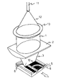
図1にはレーザー光線に対して透明な第1の加工部材5及びその下のレーザー光線に対して不透明な第2の加工部材6も図示している。図では説明上、加工部材5は透明な物体として図示しているが、この部材が着色してないわけではない。加工部材6は接触面7よりも下方に構成したレーザー光線3では軟化しない表面領域8を伴った構造を有している。透明な加工部材5は図1に示すものとは異なる従来の技術のようなものでもよい。その場合は、不適切な加熱となるので、上部の加工部材5が下部の加工部材6の表面を覆わないようにする。図1で明らかなように、絞られた光線域4の周りのエネルギー密度が高い領域は接触面7の領域にある。変換したレーザー光線3の表面領域8におけるエネルギー密度は表面領域を溶解する程ではない。その結果、接触面が軟化するのみで、既知の技術および方法によってこの領域において加工部材5、6を接合できる。従来技術とは異なり、レーザー光線を下方に構成した表面領域へも照射できれば問題はない。その結果マスクは不要となる。接触面7を有する加工部材5、6を絞られた光線域4に配置することが重要である。高さh及び幅bを変えることによって、レーザー光線を加工部材5、6における構造の形状に適合することができる。
FIG. 1 also shows a
図3には標準のレーザーダイオード9の模式的構成を示し、円錐状のレーザー光線1が円柱レンズ2へと導かれる。図1と同様に、レーザー光線1は円柱レンズ2によりレーザー光線3へと変換され、下方の表面域8は対象外として、溶接すべき表面域10上を動く。溶接すべき表面域10は加工部材の全表面と同一ではないことに留意すべきである。加工部材5、6とレーザー光線3との相対的な動きが重要であることも明かである。実施例では加工部材5、6が動くようになっている。
FIG. 3 shows a schematic configuration of a
図4の実施例では、光導波路11からの円錐状レーザー光線12は球面集光レンズ13を介して円柱レンズ2へと導かれる。
In the embodiment of FIG. 4, the
実施例では線状のレーザー光線と加工部材とが相対的に動くようになっている。線状のレーザー光線に代わりに点状のレーザー光線を表面に照射してもよい。 In the embodiment, the linear laser beam and the processing member move relatively. Instead of the linear laser beam, the surface may be irradiated with a dot laser beam.
1 レーザー光線
2 円柱レンズ
3 変換されたレーザー光線
4 絞られた光線域
5、6 加工部材
7 接触面
8 表面領域
9 レーザーダイオード
10 表面領域
11 光導波路
12 円錐状レーザー光線
13 球面レンズ
DESCRIPTION OF
Claims (2)
Applications Claiming Priority (1)
| Application Number | Priority Date | Filing Date | Title |
|---|---|---|---|
| EP03011610A EP1479506B1 (en) | 2003-05-22 | 2003-05-22 | Laser welding method for structured plastics |
Publications (2)
| Publication Number | Publication Date |
|---|---|
| JP2005178351A JP2005178351A (en) | 2005-07-07 |
| JP3866732B2 true JP3866732B2 (en) | 2007-01-10 |
Family
ID=33040992
Family Applications (1)
| Application Number | Title | Priority Date | Filing Date |
|---|---|---|---|
| JP2004127963A Expired - Fee Related JP3866732B2 (en) | 2003-05-22 | 2004-04-23 | Laser bonding method for resin structures |
Country Status (8)
| Country | Link |
|---|---|
| US (1) | US20040231788A1 (en) |
| EP (1) | EP1479506B1 (en) |
| JP (1) | JP3866732B2 (en) |
| CN (1) | CN100471656C (en) |
| AT (1) | ATE302683T1 (en) |
| DE (1) | DE50301047D1 (en) |
| ES (1) | ES2248672T3 (en) |
| HK (1) | HK1070325A1 (en) |
Families Citing this family (14)
| Publication number | Priority date | Publication date | Assignee | Title |
|---|---|---|---|---|
| US7377040B2 (en) * | 2003-12-19 | 2008-05-27 | Continental Automotive Systems Us, Inc. | Method of manufacturing a polymeric bodied fuel injector |
| US7481378B2 (en) * | 2003-12-19 | 2009-01-27 | Continental Automotive Systems Us, Inc. | Polymeric bodied fuel injector |
| US7538295B2 (en) | 2005-04-21 | 2009-05-26 | Hewlett-Packard Development Company, L.P. | Laser welding system |
| DE102005023791A1 (en) * | 2005-05-19 | 2006-11-23 | Norgren Gmbh | Fluidic control device and method for its production |
| JP5122368B2 (en) * | 2008-05-15 | 2013-01-16 | リコー光学株式会社 | Microchip substrate bonding method and general-purpose microchip |
| JP2011201237A (en) * | 2010-03-26 | 2011-10-13 | Yamatake Corp | Housing assembly structure and housing assembling method |
| US8586183B2 (en) | 2011-01-13 | 2013-11-19 | Sabic Innovative Plastics Ip B.V. | Thermoplastic compositions, method of manufacture, and uses thereof |
| US9787345B2 (en) * | 2014-03-31 | 2017-10-10 | Apple Inc. | Laser welding of transparent and opaque materials |
| US10200516B2 (en) | 2014-08-28 | 2019-02-05 | Apple Inc. | Interlocking ceramic and optical members |
| CN105108331A (en) * | 2015-07-28 | 2015-12-02 | 上海信耀电子有限公司 | Shaping light pipe and laser welding technology |
| JP6047693B1 (en) * | 2016-02-23 | 2016-12-21 | 精電舎電子工業株式会社 | Laser welding apparatus and laser welding method |
| CN106881872A (en) * | 2016-12-29 | 2017-06-23 | 平湖波科激光有限公司 | The multiwavelength laser welding method and multi-wave length laser device of laminated plastics |
| WO2018184131A1 (en) * | 2017-04-03 | 2018-10-11 | GM Global Technology Operations LLC | Smoothing method for enhanced weld surface quality |
| DE102017116110A1 (en) * | 2017-07-18 | 2019-01-24 | ConsultEngineerIP AG | optical head |
Family Cites Families (3)
| Publication number | Priority date | Publication date | Assignee | Title |
|---|---|---|---|---|
| FR2624041A1 (en) * | 1987-12-02 | 1989-06-09 | Otic Fischer & Porter | WELDING METHOD USING A LASER BEAM, ESPECIALLY APPLICABLE TO WELDING GLASS PARTS |
| US5893959A (en) * | 1994-03-31 | 1999-04-13 | Marquardt Gmbh | Workpiece of plastic and production process for such a workpiece |
| DE59900005D1 (en) * | 1999-01-28 | 2000-06-15 | Leister Process Technologies S | Laser joining method and device for connecting various workpieces made of plastic or plastic with other materials |
-
2003
- 2003-05-22 EP EP03011610A patent/EP1479506B1/en not_active Expired - Lifetime
- 2003-05-22 DE DE50301047T patent/DE50301047D1/en not_active Expired - Lifetime
- 2003-05-22 AT AT03011610T patent/ATE302683T1/en not_active IP Right Cessation
- 2003-05-22 ES ES03011610T patent/ES2248672T3/en not_active Expired - Lifetime
-
2004
- 2004-04-23 JP JP2004127963A patent/JP3866732B2/en not_active Expired - Fee Related
- 2004-05-18 US US10/848,491 patent/US20040231788A1/en not_active Abandoned
- 2004-05-21 CN CNB2004100475295A patent/CN100471656C/en not_active Expired - Fee Related
-
2005
- 2005-04-12 HK HK05103091A patent/HK1070325A1/en not_active IP Right Cessation
Also Published As
| Publication number | Publication date |
|---|---|
| EP1479506A1 (en) | 2004-11-24 |
| HK1070325A1 (en) | 2005-06-17 |
| DE50301047D1 (en) | 2005-09-29 |
| JP2005178351A (en) | 2005-07-07 |
| EP1479506B1 (en) | 2005-08-24 |
| CN1572471A (en) | 2005-02-02 |
| CN100471656C (en) | 2009-03-25 |
| US20040231788A1 (en) | 2004-11-25 |
| ATE302683T1 (en) | 2005-09-15 |
| ES2248672T3 (en) | 2006-03-16 |
Similar Documents
| Publication | Publication Date | Title |
|---|---|---|
| KR100348169B1 (en) | Laser joining method and a device for joining different workpieces made of plastic or joining plastic to other materials | |
| KR101906030B1 (en) | Method and device for welding two thermoplastic parts to be joined along a weld seam by means of a laser | |
| JP3866732B2 (en) | Laser bonding method for resin structures | |
| CN103842156B (en) | For carrying out the method and apparatus of laser weld to two elements to be joined be made of plastics | |
| JP5364039B2 (en) | Manufacturing method of resin molded products | |
| JP5030871B2 (en) | Resin welding method | |
| JP2001334578A (en) | Method for welding resin by laser | |
| KR20190055092A (en) | Welding method and system using energy beam repeatedly scanned in two dimensions | |
| US20210276128A1 (en) | Butt welding with ultrashort pulse laser beams, and optical elements joined together from individual parts | |
| JP4378634B2 (en) | Butt laser welding method and butt laser welding apparatus | |
| JP3515003B2 (en) | Laser fusion method | |
| JP2010277870A (en) | Method for manufacturing resin mold assembly | |
| JP2003136262A (en) | Laser welding method for material of different thickness | |
| JP2005001172A (en) | Laser processing method | |
| JP5669910B2 (en) | Laser welding equipment for resin molded products | |
| JP4185405B2 (en) | Bonding method between resin materials | |
| JP5000982B2 (en) | Laser welding method for differential thickness materials | |
| JP2005028784A (en) | Laser welding method | |
| JP5603664B2 (en) | Manufacturing method of resin molded products | |
| JP4584683B2 (en) | Condensing head for laser welding | |
| JPH07214360A (en) | Laser beam machining | |
| JP2005104132A (en) | Method for joining fluorine resin material | |
| JP2003311452A (en) | Laser brazing method and device | |
| JP2004195829A (en) | Laser welding method and member to be welded | |
| JPS60213387A (en) | Method and device for welding plate materials |
Legal Events
| Date | Code | Title | Description |
|---|---|---|---|
| A977 | Report on retrieval |
Free format text: JAPANESE INTERMEDIATE CODE: A971007 Effective date: 20060803 |
|
| A131 | Notification of reasons for refusal |
Free format text: JAPANESE INTERMEDIATE CODE: A131 Effective date: 20060815 |
|
| A521 | Request for written amendment filed |
Free format text: JAPANESE INTERMEDIATE CODE: A523 Effective date: 20060901 |
|
| TRDD | Decision of grant or rejection written | ||
| A01 | Written decision to grant a patent or to grant a registration (utility model) |
Free format text: JAPANESE INTERMEDIATE CODE: A01 Effective date: 20061003 |
|
| A61 | First payment of annual fees (during grant procedure) |
Free format text: JAPANESE INTERMEDIATE CODE: A61 Effective date: 20061005 |
|
| R150 | Certificate of patent or registration of utility model |
Free format text: JAPANESE INTERMEDIATE CODE: R150 |
|
| FPAY | Renewal fee payment (event date is renewal date of database) |
Free format text: PAYMENT UNTIL: 20091013 Year of fee payment: 3 |
|
| FPAY | Renewal fee payment (event date is renewal date of database) |
Free format text: PAYMENT UNTIL: 20101013 Year of fee payment: 4 |
|
| FPAY | Renewal fee payment (event date is renewal date of database) |
Free format text: PAYMENT UNTIL: 20111013 Year of fee payment: 5 |
|
| LAPS | Cancellation because of no payment of annual fees |