JP3865906B2 - Image display device - Google Patents
Image display device Download PDFInfo
- Publication number
- JP3865906B2 JP3865906B2 JP32983597A JP32983597A JP3865906B2 JP 3865906 B2 JP3865906 B2 JP 3865906B2 JP 32983597 A JP32983597 A JP 32983597A JP 32983597 A JP32983597 A JP 32983597A JP 3865906 B2 JP3865906 B2 JP 3865906B2
- Authority
- JP
- Japan
- Prior art keywords
- optical system
- image display
- decentered
- axis
- display element
- Prior art date
- Legal status (The legal status is an assumption and is not a legal conclusion. Google has not performed a legal analysis and makes no representation as to the accuracy of the status listed.)
- Expired - Fee Related
Links
- 230000003287 optical effect Effects 0.000 claims description 395
- 210000001747 pupil Anatomy 0.000 claims description 153
- 238000005286 illumination Methods 0.000 claims description 51
- 230000005540 biological transmission Effects 0.000 claims description 17
- 210000001508 eye Anatomy 0.000 claims description 15
- 210000005252 bulbus oculi Anatomy 0.000 claims description 12
- 210000003128 head Anatomy 0.000 claims description 7
- 238000010586 diagram Methods 0.000 description 38
- 230000004075 alteration Effects 0.000 description 29
- 210000001525 retina Anatomy 0.000 description 23
- 239000013307 optical fiber Substances 0.000 description 10
- 230000009471 action Effects 0.000 description 8
- 206010010071 Coma Diseases 0.000 description 7
- 230000014509 gene expression Effects 0.000 description 7
- 201000009310 astigmatism Diseases 0.000 description 6
- 239000010408 film Substances 0.000 description 6
- 239000004973 liquid crystal related substance Substances 0.000 description 6
- 238000002834 transmittance Methods 0.000 description 6
- 239000011521 glass Substances 0.000 description 5
- 238000009826 distribution Methods 0.000 description 4
- 230000004907 flux Effects 0.000 description 4
- 238000003384 imaging method Methods 0.000 description 4
- 230000008859 change Effects 0.000 description 3
- 230000000694 effects Effects 0.000 description 3
- 229910052751 metal Inorganic materials 0.000 description 3
- 239000002184 metal Substances 0.000 description 3
- 230000001936 parietal effect Effects 0.000 description 3
- 238000012937 correction Methods 0.000 description 2
- 230000004048 modification Effects 0.000 description 2
- 238000012986 modification Methods 0.000 description 2
- 239000000758 substrate Substances 0.000 description 2
- 239000010409 thin film Substances 0.000 description 2
- 238000010521 absorption reaction Methods 0.000 description 1
- 229910052782 aluminium Inorganic materials 0.000 description 1
- XAGFODPZIPBFFR-UHFFFAOYSA-N aluminium Chemical compound [Al] XAGFODPZIPBFFR-UHFFFAOYSA-N 0.000 description 1
- 238000005452 bending Methods 0.000 description 1
- 230000008901 benefit Effects 0.000 description 1
- 238000005253 cladding Methods 0.000 description 1
- 238000007796 conventional method Methods 0.000 description 1
- 239000005337 ground glass Substances 0.000 description 1
- 238000001746 injection moulding Methods 0.000 description 1
- 238000004519 manufacturing process Methods 0.000 description 1
- 239000011159 matrix material Substances 0.000 description 1
- 238000005259 measurement Methods 0.000 description 1
- 238000000465 moulding Methods 0.000 description 1
- 230000010287 polarization Effects 0.000 description 1
- 238000005498 polishing Methods 0.000 description 1
- 229910052709 silver Inorganic materials 0.000 description 1
- 239000004332 silver Substances 0.000 description 1
- 230000005236 sound signal Effects 0.000 description 1
- 238000001228 spectrum Methods 0.000 description 1
- 239000013585 weight reducing agent Substances 0.000 description 1
Images


Classifications
-
- G—PHYSICS
- G02—OPTICS
- G02B—OPTICAL ELEMENTS, SYSTEMS OR APPARATUS
- G02B17/00—Systems with reflecting surfaces, with or without refracting elements
- G02B17/08—Catadioptric systems
- G02B17/0856—Catadioptric systems comprising a refractive element with a reflective surface, the reflection taking place inside the element, e.g. Mangin mirrors
- G02B17/086—Catadioptric systems comprising a refractive element with a reflective surface, the reflection taking place inside the element, e.g. Mangin mirrors wherein the system is made of a single block of optical material, e.g. solid catadioptric systems
-
- G—PHYSICS
- G02—OPTICS
- G02B—OPTICAL ELEMENTS, SYSTEMS OR APPARATUS
- G02B17/00—Systems with reflecting surfaces, with or without refracting elements
- G02B17/08—Catadioptric systems
-
- G—PHYSICS
- G02—OPTICS
- G02B—OPTICAL ELEMENTS, SYSTEMS OR APPARATUS
- G02B17/00—Systems with reflecting surfaces, with or without refracting elements
- G02B17/08—Catadioptric systems
- G02B17/0804—Catadioptric systems using two curved mirrors
- G02B17/0816—Catadioptric systems using two curved mirrors off-axis or unobscured systems in which not all of the mirrors share a common axis of rotational symmetry, e.g. at least one of the mirrors is warped, tilted or decentered with respect to the other elements
-
- G—PHYSICS
- G02—OPTICS
- G02B—OPTICAL ELEMENTS, SYSTEMS OR APPARATUS
- G02B17/00—Systems with reflecting surfaces, with or without refracting elements
- G02B17/08—Catadioptric systems
- G02B17/082—Catadioptric systems using three curved mirrors
- G02B17/0832—Catadioptric systems using three curved mirrors off-axis or unobscured systems in which not all of the mirrors share a common axis of rotational symmetry, e.g. at least one of the mirrors is warped, tilted or decentered with respect to the other elements
-
- G—PHYSICS
- G02—OPTICS
- G02B—OPTICAL ELEMENTS, SYSTEMS OR APPARATUS
- G02B17/00—Systems with reflecting surfaces, with or without refracting elements
- G02B17/08—Catadioptric systems
- G02B17/0856—Catadioptric systems comprising a refractive element with a reflective surface, the reflection taking place inside the element, e.g. Mangin mirrors
-
- G—PHYSICS
- G02—OPTICS
- G02B—OPTICAL ELEMENTS, SYSTEMS OR APPARATUS
- G02B27/00—Optical systems or apparatus not provided for by any of the groups G02B1/00 - G02B26/00, G02B30/00
- G02B27/01—Head-up displays
- G02B27/017—Head mounted
- G02B27/0172—Head mounted characterised by optical features
-
- G—PHYSICS
- G02—OPTICS
- G02B—OPTICAL ELEMENTS, SYSTEMS OR APPARATUS
- G02B27/00—Optical systems or apparatus not provided for by any of the groups G02B1/00 - G02B26/00, G02B30/00
- G02B27/01—Head-up displays
- G02B27/017—Head mounted
- G02B2027/0178—Eyeglass type
-
- G—PHYSICS
- G02—OPTICS
- G02B—OPTICAL ELEMENTS, SYSTEMS OR APPARATUS
- G02B5/00—Optical elements other than lenses
- G02B5/30—Polarising elements
Description
【0001】
【発明の属する技術分野】
本発明は、画像表示装置に関し、特に、観察者の頭部又は顔面に保持することを可能にする頭部又は顔面装着式画像表示装置に関する。
【0002】
【従来の技術】
近年、個人が大画面の画像を楽しむことを目的として、画像表示装置が、特にその中でも頭部又は顔面装着式画像表示装置の開発が盛んになされている。
【0003】
このような中、特開平7−333551号及び特開平8−234137号において、液晶表示素子(以下、LCDと称する。)からなる画像表示素子の表示画像を観察者眼球に導く接眼光学系として、3つの光学面で囲まれた屈折率が1より大きい媒質からなる偏心光学系で構成し、液晶表示素子からの光束を第3面からその偏心光学系内に入射させ、次に、その内部で第1面で全反射させ、次いで、凹面鏡の第2面で内部反射させ、今度は第1面を経て偏心光学系外に射出させ、画像表示素子の表示像を中間像を形成することなく観察者眼球に導くようにしたものが提案されている。
【0004】
この場合は、偏心光学系を構成する光学面は3面であり、偏心光学系内部の反射回数は2回ある。この他に、2面あるいは4面以上からなり、光学系内部で1回以上反射する種々の形態の偏心光学系が本出願人等によって提案されている。
【0005】
ところで、特開平7−333551号及び特開平8−234137号においては、画像表示装置を構成するLCD(液晶表示素子)は透過型のものを予定しているが、顔面装着式画像表示装置の画像表示素子として反射型LCDを用いるものも特開平7−72446号において提案されている。図42はその画像表示装置の光学系を示す図であり、ランプ光源55からの照明光はコリメート光学系56によって平行光にされ、一部の光(S偏光)が偏光ビームスプリッタ57によって反射されて反射型LCD58を正面から照明する。反射型LCD58で反射変調された表示像は投射光学系59によりスクリーン52上に投影され、その投影像が接眼光学系53を通して観察者により拡大観察される。
【0006】
なお、反射型画像表示素子として、反射型LCDの外に、DMD(デジタル・マイクロ・デバイス)と呼ばれる画像表示素子も提案されている。これは図43に示すような構成のものである。すなわち、図43(a)に平面を、図43(b)に各要素の構成を示すように、各画素に対応する微小ミラー60が2次元的に配置され、指定したアドレスのミラー60’ を対角線を軸にして傾けることにより、ミラー60’に一定方向から入射する光を傾いていないミラーとは異なる方向へ反射させるようにして、2次元画像を表示するようにしたものであり、ミラー60各々は、一対の対角方向の角で基板61に立てられた支持ポスト62によりヒンジ63を介して支持されており、ミラー60の後側の基板61に設けられた一対の電極64の一方に電圧を印加することにより、静電力によりヒンジ63間の対角線を軸にしてミラー60が回転可能になっている(IEEE Spectrum Vol.30,No.11,pp.27〜31)。
【0007】
【発明が解決しようとする課題】
画像表示装置の光学系として偏心光学系を用いると、高い光学性能(画角、解像力等)を維持したまま装置全体を小型・軽量に構成でき、明るい画像表示装置が可能となる利点がある。しかしながら、偏心光学系と共に用いる画像表示素子としては、従来透過型LCDしか予定していなかった。そのため、特開平7−333551号及び特開平8−234137号に示された偏心光学系は、いずれも、入射瞳を無限遠に置いたテレセントリック光学系としてしか構成されてはいなかった。
【0008】
また、画像表示素子としての透過型LCDは、反射型LCDに比較して画素の開口率が低く、画素間のブラックマトリック部が目立ってしまうため、ローパスフィルタ等を用いてそれが目立たないようにする必要がある。これに対して、反射型LCDは画素の開口率が大きくすることが可能であり、上記のような問題は小さいが、特開平7−72446号に示されているように、偏心のない光学系を用いて拡大観察する場合に、光ビームスプリッタ等の光学素子を介して照明しなければならず、特に頭部又は顔面装着式画像表示装置に用いる場合に、小型・軽量化の要求に反すると共に、表示像が暗くなってしまう問題がある。
【0009】
本発明は従来技術のこのような状況に鑑みてなされたものであり、その目的は、入射瞳を有限距離に設定した非テレセントリック光学系として構成された偏心光学系を提供することにある。また、更なる目的は、その偏心光学系に反射型LCD、DMD等の反射型画像表示素子を用いて高い光学性能を有しながら小型・軽量で明るい画像表示装置を提供することにである。
【0010】
【課題を解決するための手段】
上記目的を達成する本発明の画像表示装置は、画像表示素子と、前記画像表示素子により形成された画像を虚像として観察できるように観察者眼球位置に中間像を形成することなしに導く接眼光学系とを有する画像表示装置において、前記接眼光学系が少なくとも1面の偏心した裏面反射面を有する偏心光学系からなり、且つ前記偏心光学系が、非テレセントリック光学系に構成されており、
前記画像表示素子が照明光の反射光により画像を表示する反射型画像表示素子からなり、前記照明光を形成する照明手段が前記反射型画像表示素子から前記観察者眼球位置の間の表示光路外に配置されており、
前記偏心光学系が3つの光学面で囲まれた屈折率が1より大きい媒質からなり、射出瞳が第1面に面して位置しており、前記反射型画像表示素子が第3面に面して配置され、前記反射型画像表示素子からの表示光は、透過作用を有する前記第3面5を経て前記偏心光学系内に入射し、射出瞳に面した反射作用と透過作用を有する前記第1面の内側で反射され、次いで、前記第1面に対して射出瞳側と反対側に位置する第2面に入射してその面の内側で反射され、その反射光は今度は前記第1面を透過して前記偏心光学系から射出する構成になっており、逆光線追跡で射出瞳の中心を通り前記偏心光学系を介して前記反射型画像表示素子の画面の中心に達する光線を軸上主光線とし、前記軸上主光線が射出瞳を射出し前記第1面に交差するまでの直線によって定義される軸をZ軸とし、このZ軸と直交しかつ前記偏心光学系を構成する各面の偏心面内の軸をY軸と定義し、Z軸と直交しかつY軸と直交する軸をX軸と定義し、かつ、前記反射型画像表示素子の表示面あるいは画素の面に垂直な法線nのY−Z面への投影像を法線n' とし、前記軸上主光線とその法線n' とのなす角度をΘとするとき、
前記偏心光学系の前記第3面と反対側で前記第1面と前記第2面が交差する部分が切り取られ、その切り取り面前方に前記照明手段が配置され、前記照明手段からの照明光がこの切り取り面を介して前記偏心光学系内部に入射され、前記偏心光学系を横断して前記第3面から射出され、前記反射型画像表示素子の表示面あるいは画素の面が照明され、かつ、
15°<Θ<25° ・・・(1)
を満足することを特徴とするものである。
本発明のもう1つの画像表示装置は、画像表示素子と、前記画像表示素子により形成された画像を虚像として観察できるように観察者眼球位置に中間像を形成することなしに導く接眼光学系とを有する画像表示装置において、前記接眼光学系が少なくとも1面の偏心した裏面反射面を有する偏心光学系からなり、且つ前記偏心光学系が、非テレセントリック光学系に構成されており、
前記画像表示素子が照明光の反射光により画像を表示する反射型画像表示素子からなり、前記照明光を形成する照明手段が前記反射型画像表示素子から前記観察者眼球位置の間の表示光路外に配置されており、
前記偏心光学系が3つの光学面で囲まれた屈折率が1より大きい媒質からなり、射出瞳が第1面に面して位置しており、前記反射型画像表示素子が第3面に面して配置され、前記反射型画像表示素子からの表示光は、透過作用を有する前記第3面5を経て前記偏心光学系内に入射し、射出瞳に面した反射作用と透過作用を有する前記第1面の内側で反射され、次いで、前記第1面に対して射出瞳側と反対側に位置する第2面に入射してその面の内側で反射され、その反射光は今度は前記第1面を透過して前記偏心光学系から射出する構成になっており、逆光線追跡で射出瞳の中心を通り前記偏心光学系を介して前記反射型画像表示素子の画面の中心に達する光線を軸上主光線とし、前記軸上主光線が射出瞳を射出し前記第1面に交差するまでの直線によって定義される軸をZ軸とし、このZ軸と直交しかつ前記偏心光学系を構成する各面の偏心面内の軸をY軸と定義し、Z軸と直交しかつY軸と直交する軸をX軸と定義し、かつ、前記反射型画像表示素子の表示面あるいは画素の面に垂直な法線nのY−Z面への投影像を法線n' とし、前記軸上主光線とその法線n' とのなす角度をΘとするとき、
前記照明手段が前記第1面の前の射出瞳側であって前記第3面との交差部近傍に配置され、前記照明手段からの照明光が前記第1面の前記第3面との交差部近傍から前記偏心光学系内部に入り、前記偏心光学系を横断して前記第3面から外に出て前記反射型画像表示素子の表示面あるいは画素の面を照明するように配置され、かつ、
8°<Θ<20° ・・・(3)
を満足することを特徴とするものである。
【0011】
この場合、照明光の反射型画像表示素子の表示面あるいは画素の面への入射角と反射型画像表示素子からの表示光束の主光線の射出角が略等しくなるように照明手段が配置されていることが望ましい。
【0012】
また、照明手段が偏心光学系の入射瞳位置と略共役な位置に配置されていることが望ましい。
また、偏心光学系を構成する反射面の少なくとも1面の面形状がその面内及び面外共に回転対称軸を有さない回転非対称面からなることが望ましい。その場合、その回転非対称面が、対称面を1つのみ有する面対称自由曲面からなることが望ましい。
【0013】
また、反射型画像表示素子の表示面と偏心光学系の表示光が入射する面との間のスペース及びそれを取り巻くスペースであって表示光を遮断しない光路外の位置、又は、偏心光学系の一部であって反射型画像表示素子からの表示光束が通らない部分又は方向を透過させて反射型画像表示素子の表示面あるいは画素の面を照明できる位置に、照明手段を配置することが望ましい。
【0014】
本発明においては、接眼光学系が少なくとも1面の偏心した裏面反射面を有する偏心光学系からなり、画像表示素子が照明光の反射光により画像を表示する反射型画像表示素子からなり、照明光を形成する照明手段が反射型画像表示素子から観察者眼球位置の間の表示光路外に配置されているので、反射型LCD等と偏心光学系とを用いて高い光学性能を有しながら小型・軽量で明るい画像表示装置を達成することができる。
【0015】
【発明の実施の形態】
以下、本発明の画像表示装置をいくつかの実施例に基づいて説明する。
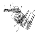
図1は、画像表示装置の接眼光学系として、特開平7−333551号及び特開平8−234137号に示されたような3つの光学面3、4、5で囲まれた屈折率が1より大きい媒質からなる偏心光学系10を用いた場合の本発明の実施例の画像表示装置の光路図である。この偏心光学系10の射出瞳1は、第1面3に面して位置しており、反射型LCD(液晶表示素子)8は第3面5に面して配置される。そして、逆光線追跡で、射出瞳1の中心を通り偏心光学系10を介して反射型LCD8の画面の中心に達する光線を偏心光学系10の軸上主光線とし、その軸上主光線を光軸2とする。
【0016】
この画像表示装置において、反射型LCD8からの表示光は、反射型LCD8に対向した透過面の第3面5を経て偏心光学系10内に入射し、射出瞳1に面した第1面3の内側で反射され、次いで、第1面3に対して射出瞳1側と反対側に位置する第2面4に入射してその面の内側で反射され、その反射光は今度は第1面3を透過して偏心光学系10から射出して、中間像を形成することなく射出瞳1の位置にある観察者の瞳に入射し、観察者の網膜上に表示像を結像する。そして、少なくとも2つの反射面は光軸2に対して偏心している。
【0017】
ここで、偏心光学系10の接眼光学系の作用を行う正パワーを主として偏心光学系10を構成する反射面3、4の何れかあるいは全てが担っており、かつ、その反射面の少なくとも1面は回転非対称な面形状を有していることが、面の偏心に基づく収差を補正するために望ましい。以下、この点を説明する。
【0018】
まず、以下の説明において用いる座標系について説明する。なお、光線追跡は、遠方の物点からの光が射出瞳1を通過し、反射型LCD8の画面を像面として結像する逆追跡で考える。
【0019】
図1に示すように、射出瞳1中心を通過し、反射型LCD8の画面の中心に達する光線を軸上主光線とし、偏心光学系10の第1面3に交差するまでの直線によって定義される光軸をZ軸とし、そのZ軸と直交しかつ撮像光学系を構成する各面の偏心面内の軸をY軸と定義し、Z軸と直交しかつY軸と直交する軸をX軸とする。
【0020】
一般に、球面レンズのみで構成された球面レンズ系では、球面により発生する球面収差と、コマ収差、像面湾曲等の収差をいくつかの面でお互いに補正しあい、全体として収差を少なくする構成になっている。一方、少ない面数で収差を良好に補正するためには非球面等が用いられる。これは、球面で発生する各種収差自体を少なくするためである。しかし、偏心した光学系においては、偏心により発生する回転非対称な収差を回転対称光学系で補正することは不可能である。
【0021】
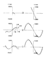
回転対称な光学系が偏心した場合、回転非対称な収差が発生し、これを回転対称な光学系でのみ補正することは不可能である。この偏心により発生する回転非対称な収差は、像歪、像面湾曲、さらに、軸上でも発生する非点収差、コマ収差がある。図36は偏心して配置された凹面鏡Mにより発生する像面湾曲、図37は偏心して配置された凹面鏡Mにより発生する非点収差、図38は偏心して配置された凹面鏡Mにより発生する軸上コマ収差を示す図である。本発明の偏心光学系は、上記のような偏心により発生する回転非対称な収差の補正のために、回転非対称な面を光学系中に配置して、その回転非対称な収差を補正している。
【0022】
偏心して配置された凹面鏡により発生する回転非対称な収差に、回転非対称な像面湾曲がある。例えば、無限遠の物点から偏心した凹面鏡に入射した光線は、凹面鏡に当たって反射結像されるが、光線が凹面鏡に当たって以降、像面(反射型LCD8)までの後側焦点距離は、光線が当たった部分の曲率の半分になる。すると、図36に示すように、軸上主光線に対して傾いた像面を形成する。このような回転非対称な像面湾曲を補正することは、回転対称な光学系では不可能であった。この傾いた像面湾曲を補正するには、凹面鏡Mを回転非対称な面で構成し、この例ではY軸正の方向(図の上方向)に対して曲率を強く(屈折力を強く)し、Y軸負の方向((図の下方向)に対して曲率を弱く(屈折力を弱く)することにより補正することができる。また、上記構成と同様な効果を持つ回転非対称な面を凹面鏡Mとは別に光学系中に配置することにより、少ない構成枚数でフラットの像面を得ることが可能となる。
【0023】
次に、回転非対称な非点収差について説明する。前記説明と同様に、偏心して配置された凹面鏡Mでは軸上光線に対しても、図37に示すような非点収差が発生する。この非点収差を補正するためには、前記説明と同様に、回転非対称面のX軸方向の曲率とY軸方向の曲率を適切に変えることによって可能となる。
【0024】
さらに、回転非対称なコマ収差について説明する。前記説明と同様に、偏心して配置された凹面鏡Mでは、軸上光線に対しても図38に示すようなコマ収差が発生する。このコマ収差を補正するためには、回転非対称面のX軸の原点から離れるに従って面の傾きを変えると共に、Y軸の正負によって面の傾きを適切に変えることによって可能となる。
【0025】
さらに、偏心光学系を折り曲げ光路を有するように構成すると、反射面にパワーを持たせることが可能となり、透過型レンズを省略することが可能となる。さらに、光路を折り曲げたことにより偏心光学系を小型に構成することが可能となる。
【0026】
また、その反射面は、臨界角を越えて光線が入射するように、光線に対して傾いて配置された全反射面で構成することにより、高い反射率にすることが可能となり、また、反射作用と透過作用とを併せ持たすことが可能となる。また、反射面を構成する面にアルミニウム又は銀等の金属薄膜を表面に形成した反射面、又は、誘電体多層膜で形成された反射面又は半透過反射面で構成することが好ましい。金属薄膜で反射作用を有する場合は、手軽に高反射率を得ることが可能となる。また、誘電体反射膜の場合は、波長選択性や吸収の少ない反射膜を形成する場合に有利となる。
【0027】
さらに好ましくは、反射面に回転非対称面を用いると、透過面に用いる場合と比べて、色収差は全く発生しない。また、面の傾きが少なくても光線を屈曲させることができるために、他の収差発生も少ない。つまり、同じ屈折力を得る場合に、反射面の方が屈折面に比べて収差の発生が少なくてすむ。
【0028】
ここで、回転非対称面には、アナモルフィック面、トーリック面、自由曲面がある。アナモルフィック面の面形状は以下の式(a)で表される。
ただし、Zは面形状の原点に対する接平面からのずれ量、CXはX軸方向曲率、CYはY軸方向曲率、Kx はX軸方向円錐係数、Ky はY軸方向円錐係数、Rn は非球面項回転対称成分、Pn は非球面項回転非対称成分である。
【0029】
トリーック面の面形状は以下の式(b)で表される。
Z=−Sign(Rx)・{(Rx−G(y))2 −x2 }1/2 +Rx
・・・(b)
ただし、Zは面形状の原点に対する接平面からのずれ量、RxはX軸方向曲率半径、Sign(Rx)はX軸方向曲率半径の符号、G(y)は、
であり、ここで、CYはY軸方向曲率、akは円錐係数、ac(n)は非球面係数である。
【0030】
自由曲面の面形状は以下の式(c)で表される。

【0031】
また、本発明の偏心光学系においては、偏心した回転非対称面形状を有する反射作用面の少なくとも1面は、対称面を1つのみ有する面対称自由曲面を使用することが望ましい。上記式(c)で表される自由曲面は、一般的には、X−Z面、Y−Z面共に対称面を持つことはないが、本発明ではxの奇数次項を全て0にすることによって、Y−Z面(図1の面)と平行な対称面が1つだけ存在する自由曲面となる。例えば、上記定義式(a)においては、C4 ,C6 ,C9 ,C11,C13,C15,C18,C20,C22,C24,C26,C28,C31,C33,C35,C37,・・・の各項の係数を0にすることによって可能である。
【0032】
また、yの奇数次項を全て0にすることによって、X−Z面と平行な対称面が1つだけ存在する自由曲面となる。
例えば、上記定義式(c)においては、C3 ,C6 ,C8 ,C10,C13,C15,C17,C19,C21,C24,C26,C28,C30,C32,C34,C36,・・・の各項の係数を0にすることによって可能であり、また、以上のような対称面を持つことにより製作性を向上することが可能となる。
【0033】
上記Y−Z面と平行な対称面、X−Z面と平行な対称面の何れか一方を対称面とすることにより、偏心により発生する回転非対称な収差を効果的に補正することが可能となる。上記定義式は、1つの例として示したものであり、他のいかなる定義式に対しても同じ効果が得られることは言うまでもない。
【0034】
また、一般に、偏心した回転非対称反射面を有する偏心光学系(偏心プリズム光学系)は研磨により製作することは難しく、研削により1面ずつ形成するか、プラスチックの射出成形又はガラスモールド成形により作製することになる。このとき、偏心プリズム光学系の面が所定の形状に作製されているかどうかを確認する必要がある。このような3次元の回転非対称な形状の測定には、一般的に3次元座標測定器が使用されるが、測定時間がかかりすぎてしまう。
【0035】
そこで、偏心プリズム光学系を構成する面の中、少なくとも1面を球面又は回転対称非球面からなる回転対称面で構成することがより望ましい。
さて、図1の本発明の実施例においては、画像表示素子として反射型LCD8を用いているため、その表示面に照明光13を照射する必要がある。そのために、この実施例の場合、点状の光源12を、第3面5と反射型LCD8の間のスペース及びそれを取り巻くスペースであって表示光を遮断しない光路外の位置に配置してある。
【0036】
しかも、反射型LCD8の表示面(画素の面が表示面に平行に配置されていない場合は画素の面)に対して偏心光学系10の入射瞳位置11と鏡像関係にある位置に光源12が配置されている。このような位置関係に配置すると、光源12からの照明光13の入射角αと反射型LCD8からの表示光束の主光線の射出角β(表示面あるいは画素の面に垂直な法線nに対して表示光束の主光線がなす角)が略等しくなり、明るい表示が可能になる。なお、入射瞳位置11は偏心光学系10に関して射出瞳1と共役な位置である。
【0037】
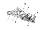
光源12の配置位置としては、図1のように第3面5と反射型LCD8の間のスペース及びそれを取り巻くスペースであって表示光を遮断しない光路外の位置以外に、図2、図3に示すように、偏心光学系10の一部であって反射型LCD8からの表示光束が通らない部分を透過させて反射型LCD8の表示面(画素の面)を照明できる位置に配置することもできる。
【0038】
図2の場合は、第3面5と反対側で第1面3と第2面4が交差する偏心光学系10の部分を切り取り、その切り取り面14前方に光源12を配置し、光源12からの照明光13がこの切り取り面14を介して偏心光学系10内部に入り、偏心光学系10を横断して第3面5から外に出て、反射型LCD8の表示面を照明するようにしている。
【0039】
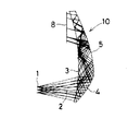
図3の場合は、第1面3の前であって第3面5との交差部近傍に光源12を配置し、光源12からの照明光13を第1面3の第3面5との交差部近傍から偏心光学系10内部に入れ、偏心光学系10を横断して第3面5から外に出るようにして、反射型LCD8の表示面を照明するようにしている。
【0040】
何れの場合も偏心光学系10内部を照明光13が通過するが、反射型LCD8からの表示光束が通らない部分あるいは方向を透過させるので、光源13は表示の邪魔にならず、また、照明光13はフレア等にならない。
【0041】
ところで、図1のように、3つの光学面3、4、5で囲まれた屈折率が1より大きい媒質からなり、射出瞳1が第1面3に面して位置しており、反射型LCD8が第3面5に面して配置され、反射型LCD8からの表示光は、反射型LCD8に対向した透過面の第3面5を経て偏心光学系10内に入射し、射出瞳1に面した第1面3の内側で反射され、次いで、第1面3に対して射出瞳1側と反対側に位置する第2面4に入射してその面の内側で反射され、その反射光は今度は第1面3を透過して偏心光学系10から射出して、中間像を形成することなく射出瞳1の位置にある観察者の瞳に入射し、観察者の網膜上に表示像を結像する偏心光学系10を接眼光学系として用いる場合について、座標系を前記のように定め、逆光線追跡で射出瞳1の中心を通り偏心光学系10を介して反射型LCD8の画面の中心に達する光線を軸上主光線とし、反射型LCD8の表示面あるいは画素の面に垂直な法線nのY−Z面への投影像を法線n' とし、上記軸上主光線とその法線n' とのなす角度をΘとするとき、照明光源12がそれぞれ図1、図2、図3の位置に配置される場合のこの角度Θの条件について検討する。
【0042】
まず、図2のように、偏心光学系10の第3面5と反対側で第1面3と第2面4が交差する部分を切り取り、その切り取り面14前方に光源12を配置し、光源12からの照明光13をこの切り取り面14を介して偏心光学系10内部に入射させ、偏心光学系10を横断して第3面5から射出した光で反射型LCD8の表示面を照明する場合には、
15°<Θ<25° ・・・(1)
を満足することが望ましい。
【0043】
上記条件式(1)の上限の25°を越えると、反射型LCD8を照明するためには、逆光線追跡での第1反射面4で照明光線を反射させる必要があり、照明むらが発生しやすく、第1反射面4が結像系以外に照明系としてのパワーも併せ持つことになるので、収差補正上好ましくない。また、下限の15°を越えると、反射型LCD8を照明するためには、逆光線追跡での第2反射面3で照明光線を反射させる必要があり、図2のように光源12を偏心光学系10の下側(反射型LCD8とは反対側)に配置すること自体が困難になってしまう。
【0044】
次に、図1のように、光源12を偏心光学系10の第3面5と反射型LCD8の間のスペース及びそれを取り巻くスペースであって表示光を遮断しない光路外の位置に配置する場合には、
20°<Θ<33° ・・・(2)
を満足することが望ましい。
【0045】
上記条件式(2)の上限の33°を越えると、偏心光学系10の像面のY方向の曲がりが大きくなり結像光学系として補正しきれなくなり、収差補正上好ましくない。また、下限の20°を越えると、照明系の光路と逆光線追跡での第2透過面5がオーバラップしてしまい、図1のように光源12を第3面5と反射型LCD8の間のスペース及びそれを取り巻くスペースであって表示光を遮断しない光路外の位置に配置すること自体が困難になってしまう。
【0046】
次に、図3のように、光源12を第1面3の前の射出瞳1側であって第3面5との交差部近傍に配置し、光源12からの照明光13を第1面3の第3面5との交差部近傍から偏心光学系10内部に入れ、偏心光学系10を横断して第3面5から外に出るようにして照明する場合には、
8°<Θ<20° ・・・(3)
を満足することが望ましい。
【0047】
上記条件式(3)の上限の20°を越えると、照明系の光路は逆光線追跡での第2透過面5の物理的な有効径の外となってしまい、図3のような照明配置をとることが困難になってしまう。また、下限の8°を越えると、照明用光源12が射出瞳1の面と第1面3とを結ぶ光路内に配置されてしまい、本来の目的である空中像が光源12に遮られて観察できなくなってしまう。
【0048】
さて、以上の実施例においては、図1に示すように、偏心光学系10は、3つの光学面3、4、5で囲まれた屈折率が1より大きい媒質からなり、反射型LCD8からの表示光が、反射型LCD8に対向した透過面の第3面5を経て偏心光学系10内に入射し、射出瞳1に面した第1面3の内側で反射され、次いで、第1面3に対して射出瞳1側と反対側に位置する第2面4に入射してその面の内側で反射され、その反射光は今度は第1面3を透過して偏心光学系10から射出して、中間像を形成することなく射出瞳1の位置にある観察者の瞳に入射し、観察者の網膜上に表示像を結像するものであったが、それ以外に種々の形態の偏心光学系10を本発明の接眼光学系として用いることができる。以下にそれらを説明するが、これらの偏心光学系10においても、少なくとも1つの反射面は光軸に対して偏心しており、偏心光学系10を構成する反射面の何れかあるいは全てが接眼光学系の作用を行う正パワーを主としてが担っており、かつ、その反射面の少なくとも1面は前記のアナモルフィック面、トーリック面、又は、自由曲面からなる回転非対称な面形状を有している。そして、偏心した回転非対称面形状を有する反射作用面の少なくとも1面は、対称面を1つのみ有する面対称自由曲面を使用することが望ましい。また、偏心光学系10を構成する面の中、少なくとも1面を球面又は回転対称非球面からなる回転対称面で構成することがより望ましい。
【0049】
図4の偏心光学系10は、4つの面3、4、5、6からなり、その間が屈折率1より大きい媒質で満たされており、反射型LCD8に対向して配置された透過面の第3面5を経て偏心光学系10に入射した反射型LCD8からの表示光は、反射面の第4面6で反射され、次に、光軸2上に射出瞳1と対向して偏心配置された反射面の第2面4に入射して反射され、その反射光は、光軸2上に第2面4と射出瞳1との間に配置された第1面3を透過して偏心光学系10から射出して光軸2に沿って進み、中間像を形成することなく射出瞳1の位置にある観察者の瞳に入射し、観察者の網膜上に表示像を結像する。
【0050】
図5の偏心光学系10は、4つの面3、4、5、6からなり、その間が屈折率1より大きい媒質で満たされており、反射型LCD8に対向して配置された透過面の第3面5を経て偏心光学系10に入射した反射型LCD8からの表示光は、光軸2上に射出瞳1と対向して偏心配置された反射面の第2面4に入射して反射され、その反射後、反射面の第4面6で反射され、次に、第2面4に入射して反射され、その反射光は、光軸2上に第2面4と射出瞳1との間に配置された第1面3を透過して偏心光学系10から射出して光軸2に沿って進み、中間像を形成することなく射出瞳1の位置にある観察者の瞳に入射し、観察者の網膜上に表示像を結像する。
【0051】
図6の偏心光学系10は、4つの面3、4、5、6からなり、その間が屈折率1より大きい媒質で満たされており、反射型LCD8に対向して配置された透過面の第3面5を経て偏心光学系10に入射した反射型LCD8からの表示光は、反射面の第4面6で反射され、次に、第3面5に入射して今度は反射され、次いで、光軸2上に射出瞳1と対向して偏心配置された反射面の第2面4に入射して反射され、その反射後、光軸2上に第2面4と射出瞳1との間に配置された第1面3を透過して偏心光学系10から射出して光軸2に沿って進み、中間像を形成することなく射出瞳1の位置にある観察者の瞳に入射し、観察者の網膜上に表示像を結像する。
【0052】
図7の偏心光学系10は、3つの面3、4、6からなり、その間が屈折率1より大きい媒質で満たされており、反射型LCD8に対向して配置され、かつ、光軸2上に射出瞳1と対向して偏心配置された第2面4を経て偏心光学系10に入射した反射型LCD8からの表示光は、反射面の第4面6で反射され、次に、第2面4に入射して今度は反射され、再び第4面6で反射され、次いで、第2面4に入射して再度反射され、その反射後、光軸2上に第2面4と射出瞳1との間に配置された第1面3を透過して偏心光学系10から射出して光軸2に沿って進み、中間像を形成することなく射出瞳1の位置にある観察者の瞳に入射し、観察者の網膜上に表示像を結像する。
【0053】
図8の偏心光学系10は、4つの面3、4、6、7からなり、その間が屈折率1より大きい媒質で満たされており、反射型LCD8に対向して配置され、かつ、光軸2上に射出瞳1と対向して偏心配置された第2面4を経て偏心光学系10に入射した反射型LCD8からの表示光は、反射面の第5面7で反射され、次に、第2面4に入射して今度は反射され、次いで、反射面の第4面6で反射され、再び第2面4に入射して再度反射され、その反射後、光軸2上に第2面4と射出瞳1との間に配置された第1面3を透過して偏心光学系10から射出して光軸2に沿って進み、中間像を形成することなく射出瞳1の位置にある観察者の瞳に入射し、観察者の網膜上に表示像を結像する。
【0054】
図9の偏心光学系10は、3つの面3、4、5からなり、その間が屈折率1より大きい媒質で満たされており、反射型LCD8に対向して配置された透過面の第3面5を経て偏心光学系10に入射した反射型LCD8からの表示光は、光軸2上に射出瞳1と対向して偏心配置された反射面の第2面4に入射して反射され、光軸2上に第2面4と射出瞳1との間に配置された第1面3を透過して偏心光学系10から射出して光軸2に沿って進み、中間像を形成することなく射出瞳1の位置にある観察者の瞳に入射し、観察者の網膜上に表示像を結像する。
【0055】
図10の偏心光学系10は、3つの面3、4、6からなり、その間が屈折率1より大きい媒質で満たされており、反射型LCD8に対向して配置され、かつ、光軸2上に射出瞳1と対向して偏心配置された第2面4を経て偏心光学系10に入射した反射型LCD8からの表示光は、反射面の第4面6で反射され、次に、第2面4に入射して今度は反射され、その反射後、光軸2上に第2面4と射出瞳1との間に配置された第1面3を透過して偏心光学系10から射出して光軸2に沿って進み、中間像を形成することなく射出瞳1の位置にある観察者の瞳に入射し、観察者の網膜上に表示像を結像する。
【0056】
図11の偏心光学系10は、3つの面3、4、6からなり、その間が屈折率1より大きい媒質で満たされており、反射型LCD8に対向して配置され、かつ、光軸2上に射出瞳1と対向して偏心配置された第2面4を経て偏心光学系10に入射した反射型LCD8からの表示光は、光軸2上に第2面4と射出瞳1との間に配置された第1面3で反射され、反射面の第4面6で反射され、次に、第2面4に入射して今度は反射され、その反射後、今度は第1面3を透過して偏心光学系10から射出して光軸2に沿って進み、中間像を形成することなく射出瞳1の位置にある観察者の瞳に入射し、観察者の網膜上に表示像を結像する。
【0057】
図12の偏心光学系10は、2つの裏面鏡21、22からなり、その中、反射型LCD8に対向して配置された第2の裏面鏡22の表面を経て偏心光学系10に入射した反射型LCD8からの表示光は、第2の裏面鏡22の表面、裏面、表面の順で透過、反射、透過し、次に、光軸2上に射出瞳1と対向して偏心配置された第1の裏面鏡21の表面、裏面、表面の順で透過、反射、透過して偏心光学系10から射出して光軸2に沿って進み、中間像を形成することなく射出瞳1の位置にある観察者の瞳に入射し、観察者の網膜上に表示像を結像する。
【0058】
図13の偏心光学系10は、正の屈折力を有する光学素子(接合レンズ)23と凹面裏面鏡21とからなり、反射型LCD8に対向して配置された正の屈折力を有する光学素子23を透過して偏心光学系10に入射した反射型LCD8からの表示光は、光軸2上に射出瞳1と対向して偏心配置された凹面裏面鏡21の表面、裏面、表面の順で透過、反射、透過して偏心光学系10から射出して光軸2に沿って進み、中間像を形成することなく射出瞳1の位置にある観察者の瞳に入射し、観察者の網膜上に表示像を結像する。
【0059】
図14の偏心光学系10は、凹面裏面鏡21と正の屈折力を有する光学素子(単レンズ)23とからなり、反射型LCD8に対向して配置された凹面裏面鏡21の表面を経て偏心光学系10に入射した反射型LCD8からの表示光は、凹面裏面鏡21の表面、裏面、表面の順で透過、反射、透過し、次に、光軸2上に射出瞳1と対向して偏心配置された正の屈折力を有する光学素子23を透過して偏心光学系10から射出して光軸2に沿って進み、中間像を形成することなく射出瞳1の位置にある観察者の瞳に入射し、観察者の網膜上に表示像を結像する。
【0060】
図15の偏心光学系10は、偏心配置の凹面裏面鏡21からなり、反射型LCD8からの表示光は、凹面裏面鏡21の表面、裏面、表面の順で透過、反射、透過して偏心光学系10から射出して光軸2に沿って進み、中間像を形成することなく射出瞳1の位置にある観察者の瞳に入射し、観察者の網膜上に表示像を結像する。
【0061】
図16の偏心光学系10は、3つの面3、4、5からなり、その間が屈折率1より大きい媒質で満たされており、反射型LCD8に対向して配置された透過面の第3面5を経て偏心光学系10に入射した反射型LCD8からの表示光は、反射面の第2面4で反射され、次に、光軸2上に射出瞳1と対向して偏心配置された第1面3に入射して反射され、その反射光は、再び第2面4に入射して反射され、光軸2上に第2面4と射出瞳1との間に配置された第1面3を透過して偏心光学系10から射出して光軸2に沿って進み、中間像を形成することなく射出瞳1の位置にある観察者の瞳に入射し、観察者の網膜上に表示像を結像する。
【0062】
図17の偏心光学系10は、4つの面3、4、5、6からなり、その間が屈折率1より大きい媒質で満たされており、反射型LCD8に対向して配置された透過面の第3面5を経て偏心光学系10に入射した反射型LCD8からの表示光は、反射面の第4面6で反射され、次に、光軸2上に射出瞳1と対向して偏心配置された第1面3に入射して反射され、その反射光は今度は第2面4に入射して反射され、光軸2上に第2面4と射出瞳1との間に配置された第1面3を透過して偏心光学系10から射出して光軸2に沿って進み、中間像を形成することなく射出瞳1の位置にある観察者の瞳に入射し、観察者の網膜上に表示像を結像する。
【0063】
図18の偏心光学系10は、2つの面3、4からなり、その間が屈折率1より大きい媒質で満たされており、反射型LCD8に対向して配置された第1面3を経て偏心光学系10に入射した反射型LCD8からの表示光は、反射面の第2面4で反射され、その反射光は、今度は第1面3に入射して反射され、その反射光は、再び第2面4に入射して反射され、光軸2上に第2面4と射出瞳1との間に配置された第1面3を透過して偏心光学系10から射出して光軸2に沿って進み、中間像を形成することなく射出瞳1の位置にある観察者の瞳に入射し、観察者の網膜上に表示像を結像する。
【0064】
図19の偏心光学系10は、3つの面3、4、5からなり、その間が屈折率1より大きい媒質で満たされており、反射型LCD8に対向して配置された透過面の第3面5を経て偏心光学系10に入射した反射型LCD8からの表示光は、光軸2上に射出瞳1と対向して配置された第1面3で反射され、再び第3面5に入射して反射され、再度第1面3で反射され、その反射光は今度は第2面4に入射して反射され、光軸2上に第2面4と射出瞳1との間に配置された第1面3を透過して偏心光学系10から射出して光軸2に沿って進み、中間像を形成することなく射出瞳1の位置にある観察者の瞳に入射し、観察者の網膜上に表示像を結像する。
【0065】
図20の偏心光学系10は、3つの面3、4、5からなり、その間が屈折率1より大きい媒質で満たされており、反射型LCD8に対向して配置された第1面3を経て偏心光学系10に入射した反射型LCD8からの表示光は、第3面5に入射して反射され、再び第1面3に入射して反射され、再度第3面5で反射され、その反射光は再度第1面3で反射され、その反射光は今度は第2面4に入射して反射され、光軸2上に第2面4と射出瞳1との間に配置された第1面3を透過して偏心光学系10から射出して光軸2に沿って進み、中間像を形成することなく射出瞳1の位置にある観察者の瞳に入射し、観察者の網膜上に表示像を結像する。
【0066】
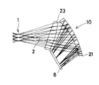
図21の偏心光学系10は、4つの面3、4、5、6からなり、その間が屈折率1より大きい媒質で満たされており、4つの面3、4、5、6中、第2面4は媒質中に設けられた偏心した半透過反射面となっているもので、反射型LCD8に対向して配置された第3面5を経て偏心光学系10に入射した反射型LCD8からの表示光は、半透過反射面の第2面4を透過して、反射面の第4面6で反射され、今度は第2面4の半透過反射面に入射して反射され、その反射後、光軸2上に第2面4と射出瞳1との間に配置された第1面3を透過して偏心光学系10から射出して光軸2に沿って進み、中間像を形成することなく射出瞳1の位置にある観察者の瞳に入射し、観察者の網膜上に表示像を結像する。
【0067】
図22の偏心光学系10は、4つの面3、4、5、6からなり、その間が屈折率1より大きい媒質で満たされており、反射型LCD8に対向して配置された第3面5を経て偏心光学系10に入射した反射型LCD8からの表示光は、反射面の第4面6で反射され、その反射光は、反射面の第2面4に入射して反射され、その反射後、第3面5から第4面6に到る光路と交差しながら光軸2上に第2面4と射出瞳1との間に配置された第1面3を透過して偏心光学系10から射出して光軸2に沿って進み、中間像を形成することなく射出瞳1の位置にある観察者の瞳に入射し、観察者の網膜上に表示像を結像する。
【0068】
図23の偏心光学系10は、4つの面3、4、5、6からなり、その間が屈折率1より大きい媒質で満たされており、4つの面3、4、5、6中、第2面4、第4面6は媒質中に設けられた偏心した半透過反射面となっているもので、反射型LCD8に対向して配置された第3面5を経て偏心光学系10に入射した反射型LCD8からの表示光は、半透過反射面の第2面4を透過して、半透過反射面の第4面6で反射され、今度は第2面4の半透過反射面に入射して反射され、その反射光は今度は半透過反射面の第4面6を透過して、光軸2上に第4面6と射出瞳1との間に配置された第1面3を透過して偏心光学系10から射出して光軸2に沿って進み、中間像を形成することなく射出瞳1の位置にある観察者の瞳に入射し、観察者の網膜上に表示像を結像する。
【0069】
次に、本発明の具体的な数値実施例1〜5について説明する。後述する各実施例の構成パラメータにおいては、図24に示すように、逆光線追跡で、偏心光学系10の射出瞳1の中心を光学系の原点として、光軸2を射出瞳1の中心(原点)を通る軸上主光線で定義し、射出瞳1から光軸2に沿って進む方向をZ軸方向、このZ軸に直交し射出瞳1中心を通り、光線が偏心光学系10によって折り曲げられる面内の方向をY軸方向、Y軸、Z軸に直交し、射出瞳1中心を通る方向をX軸方向とし、射出瞳1から偏心光学系10に向かう方向をZ軸の正方向、光軸2から像面(画像表示素子)8の側をY軸の正方向、そしてこれらY軸、Z軸と右手系を構成する方向をX軸の正方向とする。なお、光線追跡は偏心光学系10の射出瞳1側の物体側から偏心光学系10に入射する方向としている。
【0070】
そして、偏心が与えられている面については、その面の面頂位置の偏心光学系10の原点である射出瞳1の中心からのX軸方向、Y軸方向、Z軸方向の偏心量と、その面の中心軸(自由曲面、回転対称非球面については、それぞれ以下の(c)式、(f)式のZ軸)のX軸、Y軸、Z軸それぞれを中心とする傾き角(それぞれα、β、γ)とが与えられている。なお、その場合、αとβの正はそれぞれの軸の正方向に対しての反時計回りを、γの正はZ軸の正方向に対しての時計回りを意味する。その他、球面の曲率半径、面間隔、媒質の屈折率、アッベ数が慣用法に従って与えられている。
【0071】
なお、回転非対称面である自由曲面の形状は以下の式により定義する。その定義式のZ軸が回転非対称面の軸となる。
Z=Σn Σm CnmXn Yn-m
ただし、Σn はΣのnが0〜k、Σm はΣのmが0〜nを表す。
【0072】
また、面対称自由曲面(対称面を1つのみ有する自由曲面)を、この自由曲面を表す式により定義する場合は、その対称面により生ずる対称性をX方向に求める場合は、Xの奇数次項を0に(例えばX奇数次項の係数を0にする)、その対称面により生ずる対称性をY方向に求める場合は、Yの奇数次項を0に(例えばY奇数次項の係数を0にする)すればよい。
【0073】
ここで、例としてk=7(7次項)で、X方向に対称な面対称自由曲面を上記定義式を展開した形で表すと、以下の式となる。
【0074】
また、面対称自由曲面の他の定義式として、Zernike多項式がある。この面の形状は以下の式(d)により定義する。その定義式のZ軸がZernike多項式の軸となる。
【0075】
【0076】
本発明において使用可能なその他の面の表現例として、上記定義式(Z=Σn Σm CnmXn Yn-m )を、(c)式と同様、X方向に対称な面で、k=7とした面を表す場合、以下の(e)式のように展開することもできる。
【0077】
【0078】
【0079】
なお、後記する構成パラメータにおいて、データの記載されていない非球面に関する項は0である。屈折率についてはd線(波長587.56nm)に対するものを表記してある。長さの単位はmmである。
【0080】
次に、図24〜図28にそれぞれ数値実施例1〜5の画像表示装置光学系の偏心光学系10の光軸2を含むY−Z断面図を示す。何れの実施例の偏心プリズム光学系10も、図1の場合と同様に、3つの面3、4、5からなっており、その3つの面3〜5の間が屈折率が1より大きい透明媒質で埋められていて、不図示の物体から発した光線束が光軸2に沿って偏心光学系10の射出瞳1をまず通過し、透過作用と反射作用を有する第1面3に入射して偏心光学系10内に入り、その入射光線は射出瞳1から遠い側の反射作用のみを有する反射面である第2面4で射出瞳1に近づく方向に反射され、今度は第1面3で射出瞳1から遠ざかる方向に再び反射され、その反射光線は、透過作用のみを有する第3面5を透過して像面の位置に配置された反射型LCD8の表示面に到達し、その表示面で正反射して、図24〜図26の場合は、図2と同様に、第3面5から偏心光学系10内に入り、偏心光学系10を横断して、第3面5と反対側の第1面3と第2面4が交差する部分の切り取り面14から偏心光学系10の外へ出て、切り取り面14の前方に配置された面光源(例えば、点光源により背面から照明されたスリガラス)12に達する。また、図27の場合は、図1と同様、反射型LCD8の表示面で正反射した光は、第3面5と反射型LCD8の間のスペースの射出瞳1側に配置された面光源12に達する。さらに、図28の場合は、図3と同様、反射型LCD8の表示面で正反射した光は、第3面5から偏心光学系10内に入り第3面5と第1面3交差部近傍を横切り、第1面3から射出瞳1側に出て、第1面3の前方に配置された面光源12に達する。
【0081】
図24(実施例1)、図26(実施例3)、図27(実施例4)、図28(実施例5)の場合は、射出瞳1と面光源12は共役になっており、したがって、面光源12は射出瞳1の形状に相似の円形のものでよく、図25(実施例2)の場合は、Y−Z断面図内でのみ射出瞳1と面光源12は共役になっており、X−Z断面図内では共役になっていないため、実施例2の場合は、光源12としてX方向に伸びた長い面光源12を用いる。
【0082】
そして、実施例1、2、5においては、第1面3は瞳1側に凹面を向けて偏心した前記の(f)式で定義される回転対称非球面からなり、実施例3においては、第1面3は前記の(c)式で定義される自由曲面からなり、実施例4においては、第1面3は瞳1側に凸面を向けて偏心した前記の(f)式で定義される回転対称非球面からなる。また、実施例1〜5の何れの実施例においても、第2面4、第3面5は前記の(c)式で定義される自由曲面からなる。
【0083】
また、反射型LCD8は、何れの実施例も対角0.7インチタイプの縦横14.4mm×10.7mmの画面のものを使用するようになっており、画角は、実施例1〜3は、水平画角33°、垂直画角25.1°、実施例4、5は、水平画角35°、垂直画角26.6°であり、瞳径は、何れの実施例も4mmである。
【0084】
以下に、上記実施例1〜5の構成パラメータを示す。なお、像面の次の面番号7、8は実施例1〜3の場合は、第3面5と切り取り面14であり、実施例5の場合は、第3面5と第1面3である。また、光源は面光源12である。そして、これら実施例1〜5はいずれも入射瞳を有限距離とした非テレセントリック光学系に構成したものである。
上記実施例3の面光源12の瞳収差を示す横収差図を図29に示す。図中、▲1▼は面光源12中心から射出瞳1中心に到る光束の横収差を、▲2▼は面光源12右端から射出瞳1上端に到る光束の横収差を、▲3▼は面光源12左端から射出瞳1下端に到る光束の横収差をそれぞれ示す。
【0086】
以上の実施例1〜5の条件式(1)〜(3)に関する角度Θは次の通りである。
【0087】
なお、光学系の数値は省くが、図17の偏心光学系10を接眼光学系に用いる場合の光源12の配置に関する1実施例を図30に示す。この実施例では、光源12を第1面3の前の射出瞳1側であって第3面5に近い位置に配置し、光源12からの照明光13を第1面3から偏心光学系10内部に入れ、偏心光学系10を横断して第4面6から外に出るように、すなわち、光源12からの照明光13が偏心光学系10を射出瞳1側から反対側に突き抜けるようにし、第4面6から外に出た照明光13を凹面鏡15により反射型LCD8の方向に向け、第4面6の第3面5との交差部近傍から偏心光学系10内部に再度入れ、偏心光学系10を横断させて第3面5から外に出るようにして、反射型LCD8の表示面を照明するようにしている。
【0088】
また、上記実施例はいずれも、入射瞳を有限距離とした非テレセントリックに形成した偏心光学系に反射型LCD8を使用した形態を示したが、以下のように、2次元画面を備えていない画像表示素子を用いることも可能である。
【0089】
例えば、上記図2に示した画像表示装置の反射型LCD8を単なる平面ミラー9に置き換え、光源12をスキャン(走査)することによって、2次元画像を形成する画像表示素子24とスキャン部材25とに置き換えた図31に示す画像表示装置とすることもできる。
【0090】
この時、1次元走査を主体とした構成とするならば、例えば図32に示すように、スキャン部材25はポリゴンミラー26に構成し、画像表示素子24は1次元画像表示素子(液晶表示画素やLED等の表示画素を1次元に配列したもの)27と光を平行光束にするコリメータレンズ28とに構成することができる。ここで、偏心光学系10の入射瞳位置は、このポリゴンミラー26の回転多面に形成された反射面に略一致するように配置し、1次元画像表示素子27の画素列と直交する方向に光束を走査することによって、2次元画像を形成するように構成されている。
【0091】
また、2次元走査を主体とした構成とするならば、例えば図33に示すように、1次元画像表示素子27を1画素分の表示を行なう画素光源29に構成し、ポリゴンミラー26の走査方向と直交する方向に走査機能を持って構成されたガルバノミラー30を配置する構成とすることで実現できる。猶、このガルバノミラー30は走査機能を持てば良く、ポリゴンミラー等で構成してもかまわない。
【0092】
また、上記実施例において、光源12、反射型LCD8ポリゴンミラー26及び平面ミラー9等の光学素子から射出される光束の内、入射瞳を形成する有効光束以外の開口数の大きな光が、偏心光学系10を介して観察者の眼球に導かれることによって発生するゴースト像を防止するため、これら各素子の形成する光路中に光束の開口数を制限する開口数低減素子を配置することが望ましい。特にこの開口数低減素子は、上記各素子と偏心光学系10との間の光路中に配置することがより効果的である。この開口数低減素子としては、例えば下記に示すルーバー光学素子16aや光ファイバープレート16b等がある。
【0093】
ルーバー光学素子16aの例を図34(a)、図34(b)に示す。ルーバー光学素子16aは、透明フィルム17の中に微細な遮光壁18が周期的に挟み込まれてなるもので、この遮光壁18によりある入射角範囲以外の光は吸収されて射出できないものである。また、この遮光壁18の角度を変えることにより、最大透過の入射角を変えることができる。図34(a)、(b)の矢印の方向から光束が入射した場合のルーバー光学素子16aの透過率分布を夫々図35(a)、(b)に示す。
【0094】
このようなルーバー光学素子16aを例えば図1の光源12と反射型LCD8の間に挿入すると、光源12からの光はルーバー光学素子16aにより開口数が制限され、その後に反射型LCD8を反射し、偏心光学系10に向かう。ここで、ゴースト像を発生させる開口数の大きさが、入射角度α以上に大きい光束によってもたらされるとした時、透過率分布が、図35(a)のように臨界入射角α以上の光束は透過させないように構成されたルーバー光学素子16aを使用すれば、ゴースト像の発生を防止することができる。
【0095】
また、上記各実施例のように偏心光学系10では、各光学作用面が同軸系にはなく、面の形状自体も回転非対称に形成されていることもあり、ゴースト像を発生させる開口数の大きな光束も、図35(a)のように入射角0を中心に対称に存在しない場合もある。そこでそのような場合は、図34(b)に示すように、所定の角度傾いて入射する光束を中心に光束の透過率を制御するように、透明フィルム17中の微細な遮光壁18が所定角度傾いて配置されたルーバー光学素子16aを用いることが望ましい。例えば、図1に示した実施例の場合は、反射型LCD8を射出した光束は偏心光学系10の第3面5に対して第1面3の方向に傾いて斜めに入射する。そこでこの反射型LCD8と第3面5との間に図34(b)のルーバー光学素子16aを配置すれば、図35(b)のように透過率分布がスライドし、有効光束の光量を損失させずに、ゴースト像を形成する開口数の大きい光束のみ低減できる。
【0096】
また、このルーバー光学素子16aの代わりに、光ファイバーを束ねてプレート状に切断した光ファイバープレート16bを使用することもできる。この光ファイバープレート16bの構造の一例を図36に示す。この光ファイバープレート16bは、同図の拡大図に示すように、コアガラス19aとその周辺を囲むクラッドガラス19bとその外周に被覆された吸収部材20とからなり、所定の開口数を有する光ファイバーを多数本蜜に束ねて構成されたもので、光ファイバーの開口数で決まる開口数以上の光束は、光ファイバー壁を抜けて吸収部材20で吸収されるため、前記ルーバー光学素子16aと同じ働きを持つものである。
【0097】
さて、以上に説明したような画像表示装置を1組用意し、片眼装着用に構成しても、また、そのような組を左右一対用意し、それらを眼輻距離だけ離して支持することにより、両眼装着用に構成してもよい。そのようにして、片眼あるいは両眼で観察できる据え付け型又はポータブル型の画像表示装置として構成することができる。
【0098】
片眼に装着する構成にした場合の様子を図37に(この場合は、左眼に装着)、両眼に装着する構成にした場合の様子を図38にそれぞれ示す。図37、図38中、31は表示装置本体部を示し、図37の場合は観察者の顔面の左眼の前方に、図38の場合は観察者の顔面の両眼の前方に保持されるよう支持部材が頭部を介して固定している。その支持部材としては、一端を表示装置本体部31に接合し、観察者のこめかみから耳の上部にかけて延在する左右の前フレーム32と、前フレーム32の他端に接合され、観察者の側頭部を渡るように延在する左右の後フレーム33とから(図37の場合)、あるいは、さらに、左右の後フレーム33の他端に挟まれるように自らの両端を一方づつ接合し、観察者の頭頂部を支持する頭頂フレーム34とから(図38の場合)構成されている。
【0099】
また、前フレーム32における上記の後フレーム33との接合近傍には、弾性体からなり例えば金属板バネ等で構成されたリヤプレート35が接合されている。このリヤプレート35は、上記支持部材の一翼を担うリヤカバー36が観察者の後頭部から首のつけねにかかる部分で耳の後方に位置して支持可能となるように接合されている(図38の場合)。リヤプレート35又はリヤカバー36内にの観察者の耳に対応する位置にスピーカー39が取り付けられている。
【0100】
映像・音声信号等を外部から送信するためのケーブル41が表示装置本体部31から、頭頂フレーム34(図38の場合)、後フレーム33、前フレーム32、リヤプレート35の内部を介してリヤプレート35あるいはリヤカバー36の後端部より外部に突出している。そして、このケーブル41はビデオ再生装置40に接続されている。なお、図中、40aはビデオ再生装置40のスイッチやボリュウム調整部である。
【0101】
なお、ケーブル41は先端をジャックして、既存のビデオデッキ等に取り付け可能としてもよい。さらに、TV電波受信用チューナーに接続してTV鑑賞用としてもよいし、コンピュータに接続してコンピュータグラフィックスの映像や、コンピュータからのメッセージ映像等を受信するようにしてもよい。また、邪魔なコードを排斥するために、アンテナを接続して外部からの信号を電波によって受信するようにしても構わない。
【0102】
【発明の効果】
以上の説明から明らかなように、本発明によると、接眼光学系が少なくとも1面の偏心した裏面反射面を有する偏心光学系からなり、画像表示素子が照明光の反射光により画像を表示する反射型画像表示素子からなり、照明光を形成する照明手段が反射型画像表示素子から観察者眼球位置の間の表示光路外に配置されているので、反射型LCDと偏心光学系とを用いて高い光学性能を有しながら小型・軽量で明るい画像表示装置を達成することができる。
【図面の簡単な説明】
【図1】本発明の1実施例の画像表示装置の光路図である。
【図2】図1の変形例の画像表示装置の光路図である。
【図3】図1の別の変形例の画像表示装置の光路図である。
【図4】本発明の画像表示装置に適用可能な偏心光学系の光路図である。
【図5】本発明の画像表示装置に適用可能な別の偏心光学系の光路図である。
【図6】本発明の画像表示装置に適用可能な別の偏心光学系の光路図である。
【図7】本発明の画像表示装置に適用可能な別の偏心光学系の光路図である。
【図8】本発明の画像表示装置に適用可能な別の偏心光学系の光路図である。
【図9】本発明の画像表示装置に適用可能な別の偏心光学系の光路図である。
【図10】本発明の画像表示装置に適用可能な別の偏心光学系の光路図である。
【図11】本発明の画像表示装置に適用可能な別の偏心光学系の光路図である。
【図12】本発明の画像表示装置に適用可能な別の偏心光学系の光路図である。
【図13】本発明の画像表示装置に適用可能な別の偏心光学系の光路図である。
【図14】本発明の画像表示装置に適用可能な別の偏心光学系の光路図である。
【図15】本発明の画像表示装置に適用可能な別の偏心光学系の光路図である。
【図16】本発明の画像表示装置に適用可能な別の偏心光学系の光路図である。
【図17】本発明の画像表示装置に適用可能な別の偏心光学系の光路図である。
【図18】本発明の画像表示装置に適用可能な別の偏心光学系の光路図である。
【図19】本発明の画像表示装置に適用可能な別の偏心光学系の光路図である。
【図20】本発明の画像表示装置に適用可能な別の偏心光学系の光路図である。
【図21】本発明の画像表示装置に適用可能な別の偏心光学系の光路図である。
【図22】本発明の画像表示装置に適用可能な別の偏心光学系の光路図である。
【図23】本発明の画像表示装置に適用可能な別の偏心光学系の光路図である。
【図24】本発明の数値実施例1の画像表示装置光学系の断面図である。
【図25】本発明の数値実施例2の画像表示装置光学系の断面図である。
【図26】本発明の数値実施例3の画像表示装置光学系の断面図である。
【図27】本発明の数値実施例4の画像表示装置光学系の断面図である。
【図28】本発明の数値実施例5の画像表示装置光学系の断面図である。
【図29】本発明の数値実施例3の面光源の瞳収差を示す横収差図である。
【図30】図17の偏心光学系を用いる場合の光源の配置に関する1実施例を示す断面図である。
【図31】本発明の他の実施例を示す断面図である。
【図32】図31のスキャン部材を1次元走査に構成した例を示す図である。
【図33】図31のスキャン部材を2次元走査に構成した例を示す図である。
【図34】ルーバー光学素子を示す図である。
【図35】図34のルーバー光学素子の透過率分布を示す図である。
【図36】光ファイバープレートを示す図である。
【図37】本発明の画像表示装置を片眼装着の構成にした場合の様子を示す図である。
【図38】本発明の画像表示装置を両眼装着の構成にした場合の様子を示す図である。
【図39】偏心配置の凹面鏡により発生する像面湾曲を説明するための図である。
【図40】偏心配置の凹面鏡により発生する非点収差を説明するための図である。
【図41】偏心配置の凹面鏡により発生する軸上コマ収差を説明するための図である。
【図42】従来の反射型LCDを用いる画像表示装置の光学系を示す図である。
【図43】公知のDMDの構成を説明するための図である。
【符号の説明】
1 射出瞳
2 光軸
3 第1面
4 第2面
5 第3面
6 第4面
8 反射型LCD(液晶表示素子)
9 平面ミラー
10 偏心光学系
11 入射瞳位置
12 光源
13 照明光
14 切り取り面
15 凹面鏡
16a ルーバー光学素子
16b 光ファイバープレート
17 透明フィルム
18 遮光壁
19a コアガラス
19b クラッドガラス
20 吸収部材
21、22 裏面鏡
23 正の屈折力を有する光学素子
24 画像表示素子
25 スキャン部材
26 ポリゴンミラー
27 1次元画像表示素子
28 コリメータレンズ
29 画素光源
30 ガルバノメータミラー
31 表示装置本体部
32 前フレーム
33 後フレーム
34 頭頂フレーム
35 リヤプレート
36 リヤカバー
39 スピーカー
41 ケーブル
40 ビデオ再生装置
40a ボリュウム調整部
M 凹面鏡[0001]
BACKGROUND OF THE INVENTION
The present invention relates to an image display device, and more particularly to a head- or face-mounted image display device that can be held on an observer's head or face.
[0002]
[Prior art]
In recent years, for the purpose of allowing an individual to enjoy a large screen image, an image display device, particularly a head- or face-mounted image display device, has been actively developed.
[0003]
Under such circumstances, in Japanese Patent Laid-Open Nos. 7-333551 and 8-234137, as an eyepiece optical system for guiding a display image of an image display element made up of a liquid crystal display element (hereinafter referred to as LCD) to an observer's eyeball, A decentered optical system composed of a medium surrounded by three optical surfaces and having a refractive index larger than 1, and a light beam from a liquid crystal display element is incident on the decentered optical system from the third surface. Totally reflect on the first surface, then internally reflect on the second surface of the concave mirror, and then emit through the first surface to the outside of the decentered optical system, observing the display image of the image display element without forming an intermediate image What has been guided to the human eye has been proposed.
[0004]
In this case, there are three optical surfaces constituting the decentered optical system, and the number of reflections inside the decentered optical system is two. In addition to this, various forms of decentered optical systems that consist of two or more surfaces and reflect one or more times within the optical system have been proposed by the present applicant.
[0005]
Incidentally, in JP-A-7-333551 and JP-A-8-234137, an LCD (liquid crystal display element) constituting the image display device is planned to be a transmissive type, but the image of the face-mounted image display device is used. An apparatus using a reflective LCD as a display element is also proposed in Japanese Patent Laid-Open No. 7-72446. FIG. 42 is a diagram showing an optical system of the image display device. Illumination light from the
[0006]
In addition to the reflective LCD, an image display element called DMD (digital micro device) has been proposed as a reflective image display element. This has a structure as shown in FIG. That is, as shown in FIG. 43 (a) and the configuration of each element in FIG. 43 (b),
[0007]
[Problems to be solved by the invention]
When an eccentric optical system is used as the optical system of the image display device, there is an advantage that the entire device can be configured to be small and light while maintaining high optical performance (field angle, resolution, etc.), and a bright image display device can be realized. However, only a transmissive LCD has been planned as an image display element to be used with the decentered optical system. For this reason, the decentered optical systems disclosed in JP-A-7-333551 and JP-A-8-234137 have only been configured as telecentric optical systems in which the entrance pupil is placed at infinity.
[0008]
In addition, a transmissive LCD as an image display element has a lower pixel aperture ratio than a reflective LCD, and a black matrix portion between pixels becomes conspicuous, so that it is not conspicuous using a low-pass filter or the like. There is a need to. On the other hand, the reflective LCD can increase the aperture ratio of the pixels, and the above problems are small. However, as shown in Japanese Patent Laid-Open No. 7-72446, an optical system without decentration is used. When magnifying observation using a light source, it must be illuminated through an optical element such as a light beam splitter, and this is contrary to the demand for miniaturization and weight reduction, particularly when used for a head or face-mounted image display device. There is a problem that the display image becomes dark.
[0009]
The present invention has been made in view of such a situation in the prior art, and an object thereof is to provide a decentered optical system configured as a non-telecentric optical system in which an entrance pupil is set to a finite distance. A further object is to provide a small, lightweight and bright image display device having high optical performance by using a reflective image display element such as a reflective LCD or DMD in its decentered optical system.
[0010]
[Means for Solving the Problems]
An image display device of the present invention that achieves the above object includes an image display element and an eyepiece optical that guides an image formed by the image display element without forming an intermediate image at an observer eyeball position so that an image can be observed as a virtual image. The eyepiece optical system comprises a decentered optical system having at least one decentered back surface reflecting surface, and the decentered optical system is configured as a non-telecentric optical system,
The image display element includes a reflective image display element that displays an image by reflected light of illumination light, and an illuminating unit that forms the illumination light is outside the display optical path between the reflective image display element and the observer eyeball position. Are located in
The decentered optical system is made of a medium having a refractive index larger than 1 surrounded by three optical surfaces, the exit pupil is located facing the first surface, and the reflective image display element faces the third surface. The display light from the reflective image display element is incident on the decentered optical system via the
A portion where the first surface and the second surface intersect with each other on the side opposite to the third surface of the decentered optical system is cut out, the illuminating means is disposed in front of the cut surface, and illumination light from the illuminating means Is incident on the decentered optical system through the cut surface, is emitted from the third surface across the decentered optical system, the display surface of the reflective image display element or the surface of the pixel is illuminated, and
15 ° <Θ <25 ° (1)
It is characterized by satisfying.
Another image display device of the present invention includes an image display element, and an eyepiece optical system that guides an image formed by the image display element without forming an intermediate image at an observer eyeball position so that an image can be observed as a virtual image. The eyepiece optical system comprises a decentered optical system having at least one decentered back surface reflecting surface, and the decentered optical system is configured as a non-telecentric optical system,
The image display element includes a reflective image display element that displays an image by reflected light of illumination light, and an illuminating unit that forms the illumination light is outside the display optical path between the reflective image display element and the observer eyeball position. Are located in
The decentered optical system is made of a medium having a refractive index larger than 1 surrounded by three optical surfaces, the exit pupil is located facing the first surface, and the reflective image display element faces the third surface. The display light from the reflective image display element is incident on the decentered optical system via the
The illumination means is disposed on the exit pupil side in front of the first surface and in the vicinity of the intersection with the third surface, and the illumination light from the illumination means intersects the third surface of the first surface. Arranged so as to enter the decentered optical system from the vicinity of the unit, cross the decentered optical system, exit from the third surface, and illuminate the display surface or the pixel surface of the reflective image display element, and ,
8 ° <Θ <20 ° (3)
It is characterized by satisfying.
[0011]
In this case, the illumination means is arranged so that the incident angle of the illumination light to the display surface or pixel surface of the reflective image display element is substantially equal to the emission angle of the principal ray of the display light beam from the reflective image display element. It is desirable.
[0012]
In addition, it is desirable that the illumination means is disposed at a position substantially conjugate with the entrance pupil position of the decentered optical system.
Further, it is desirable that the surface shape of at least one of the reflecting surfaces constituting the decentered optical system is a rotationally asymmetric surface that does not have a rotationally symmetric axis both inside and outside the surface. In that case, it is desirable that the rotationally asymmetric surface is a plane-symmetric free-form surface having only one symmetry surface.
[0013]
In addition, the space between the display surface of the reflective image display element and the surface on which the display light of the decentration optical system is incident and the space surrounding it, and the position outside the optical path that does not block the display light, or of the decentration optical system It is desirable to arrange the illumination means at a position where a part or direction through which the display light beam from the reflective image display element does not pass can be transmitted and the display surface or pixel surface of the reflective image display element can be illuminated. .
[0014]
In the present invention, the eyepiece optical system is composed of a decentered optical system having at least one decentered back surface reflecting surface, the image display element is composed of a reflective image display element that displays an image by reflected light of illumination light, and illumination light Is arranged outside the display optical path between the reflective image display element and the position of the observer's eyeball, so that it has a small size and high optical performance using a reflective LCD or the like and a decentered optical system. A lightweight and bright image display device can be achieved.
[0015]
DETAILED DESCRIPTION OF THE INVENTION
Hereinafter, an image display device of the present invention will be described based on some embodiments.
FIG. 1 shows an eyepiece optical system of an image display device having a refractive index surrounded by three
[0016]
In this image display device, display light from the
[0017]
Here, any or all of the reflecting
[0018]
First, a coordinate system used in the following description will be described. Note that ray tracing is considered by reverse tracing in which light from a distant object point passes through the
[0019]
As shown in FIG. 1, a light beam that passes through the center of the
[0020]
In general, in a spherical lens system composed of only spherical lenses, the spherical aberration generated by the spherical surface, coma aberration, curvature of field, and other aberrations are corrected with respect to each other to reduce aberrations as a whole. It has become. On the other hand, an aspherical surface or the like is used to satisfactorily correct aberrations with a small number of surfaces. This is to reduce various aberrations that occur on the spherical surface. However, in a decentered optical system, it is impossible to correct rotationally asymmetric aberration caused by the decentration with a rotationally symmetric optical system.
[0021]
When a rotationally symmetric optical system is decentered, rotationally asymmetric aberration is generated, and this cannot be corrected only by the rotationally symmetric optical system. The rotationally asymmetric aberration generated by this decentration includes image distortion, curvature of field, and astigmatism and coma generated on the axis. 36 is a field curvature generated by the decentered concave mirror M, FIG. 37 is an astigmatism generated by the decentered concave mirror M, and FIG. 38 is an on-axis coma generated by the decentered concave mirror M. It is a figure which shows an aberration. The decentered optical system of the present invention corrects the rotationally asymmetric aberration by arranging a rotationally asymmetric surface in the optical system in order to correct the rotationally asymmetric aberration caused by the decentration as described above.
[0022]
One example of rotationally asymmetric aberration generated by a decentered concave mirror is rotationally asymmetric field curvature. For example, a light ray incident on a concave mirror decentered from an object point at infinity is reflected and imaged by hitting the concave mirror, but after the light ray hits the concave mirror, the rear focal distance to the image plane (reflective LCD 8) hits the light ray. It becomes half the curvature of the part. Then, as shown in FIG. 36, an image plane inclined with respect to the axial principal ray is formed. It has been impossible to correct such rotationally asymmetric field curvature with a rotationally symmetric optical system. In order to correct this tilted field curvature, the concave mirror M is composed of a rotationally asymmetric surface. In this example, the curvature is increased (refractive power is increased) with respect to the positive Y-axis direction (upward in the figure). This can be corrected by making the curvature weak (refracting power weak) with respect to the negative direction of the Y axis (the downward direction of the figure), and a rotationally asymmetric surface having the same effect as the above configuration is a concave mirror. By arranging it in the optical system separately from M, it is possible to obtain a flat image surface with a small number of components.
[0023]
Next, rotationally asymmetric astigmatism will be described. As in the above description, in the concave mirror M arranged eccentrically, astigmatism as shown in FIG. In order to correct this astigmatism, it is possible to appropriately change the curvature in the X-axis direction and the curvature in the Y-axis direction of the rotationally asymmetric surface, as described above.
[0024]
Further, rotationally asymmetric coma will be described. Similarly to the above description, in the concave mirror M arranged eccentrically, coma aberration as shown in FIG. In order to correct this coma, it is possible to change the inclination of the surface as it moves away from the origin of the X axis of the rotationally asymmetric surface and to change the inclination of the surface appropriately depending on whether the Y axis is positive or negative.
[0025]
Further, when the decentered optical system is configured to have a bent optical path, it is possible to give power to the reflecting surface and to omit the transmission type lens. Furthermore, the decentered optical system can be made compact by bending the optical path.
[0026]
In addition, the reflection surface can be made highly reflective by being composed of a total reflection surface that is inclined with respect to the light beam so that the light beam is incident beyond the critical angle. It is possible to have both an action and a permeation action. Moreover, it is preferable to comprise a reflective surface in which a metal thin film such as aluminum or silver is formed on the surface constituting the reflective surface, or a reflective surface or a transflective surface formed of a dielectric multilayer film. When the metal thin film has a reflecting action, it is possible to easily obtain a high reflectance. In the case of a dielectric reflection film, it is advantageous when forming a reflection film with little wavelength selectivity and absorption.
[0027]
More preferably, when a rotationally asymmetric surface is used for the reflecting surface, no chromatic aberration is generated as compared with the case of using the transmitting surface. In addition, since the light beam can be bent even when the surface inclination is small, other aberrations are less likely to occur. That is, when the same refractive power is obtained, the reflective surface requires less aberration than the refractive surface.
[0028]
Here, the rotationally asymmetric surface includes an anamorphic surface,ToricThere are surfaces and free-form surfaces. The surface shape of the anamorphic surface is represented by the following formula (a).
Where Z is the amount of deviation of the surface shape from the tangential plane, CX is the X-axis curvature, CY is the Y-axis curvature, Kx is the X-axis cone coefficient, Ky is the Y-axis cone coefficient, and Rn is an aspheric surface The term rotationally symmetric component, Pn, is an aspheric term rotationally asymmetric component.
[0029]
TrickThe surface shape of the surface is represented by the following formula (b).
Z = −Sign (Rx) · {(Rx−G (y))2 -X2 }1/2 + Rx
... (b)
However, Z is the amount of deviation from the tangential plane with respect to the origin of the surface shape, Rx is the X-axis direction radius of curvature, Sign (Rx) is the sign of the X-axis direction radius of curvature, and G (y) is
Where CY is a curvature in the Y-axis direction, ak is a conical coefficient, and ac (n) is an aspherical coefficient.
[0030]
The surface shape of the free-form surface is represented by the following formula (c).
[0031]
In the decentered optical system of the present invention, it is desirable that at least one of the reflecting action surfaces having a decentered rotationally asymmetric surface shape be a plane-symmetric free-form surface having only one symmetric surface. In general, the free-form surface represented by the above formula (c) does not have a symmetric surface in both the XZ plane and the YZ plane, but in the present invention, all odd-order terms of x are set to 0. Thus, a free-form surface having only one plane of symmetry parallel to the YZ plane (the plane of FIG. 1) is obtained. For example, in the above definition (a), CFour, C6, C9, C11, C13, C15, C18, C20, Ctwenty two, Ctwenty four, C26, C28, C31, C33, C35, C37This is possible by setting the coefficient of each term of.
[0032]
Further, by setting all odd-order terms of y to 0, a free-form surface having only one symmetry plane parallel to the XZ plane is obtained.
For example, in the above definition (c), CThree, C6, C8, CTen, C13, C15, C17, C19, Ctwenty one, Ctwenty four, C26, C28, C30, C32, C34, C36,... Can be achieved by setting the coefficient of each term to 0, and by having the symmetry plane as described above, the manufacturability can be improved.
[0033]
By using one of the symmetry plane parallel to the YZ plane and the symmetry plane parallel to the XZ plane as a symmetry plane, it is possible to effectively correct rotationally asymmetric aberration caused by decentration. Become. The above definition formula is shown as an example, and it goes without saying that the same effect can be obtained for any other definition formula.
[0034]
In general, it is difficult to manufacture a decentered optical system having a decentered rotationally asymmetric reflecting surface (decentered prism optical system) by polishing, and it is formed by grinding one surface at a time, or by plastic injection molding or glass mold molding. It will be. At this time, it is necessary to confirm whether or not the surface of the decentered prism optical system is formed in a predetermined shape. A three-dimensional coordinate measuring instrument is generally used for measuring such a three-dimensional rotationally asymmetric shape, but it takes too much measurement time.
[0035]
Therefore, it is more preferable that at least one of the surfaces constituting the decentered prism optical system is a rotationally symmetric surface made of a spherical surface or a rotationally symmetric aspheric surface.
In the embodiment of the present invention shown in FIG. 1, since the
[0036]
In addition, the
[0037]
As the arrangement position of the
[0038]
In the case of FIG. 2, a portion of the decentered
[0039]
In the case of FIG. 3, the
[0040]
In any case, the illumination light 13 passes through the decentered
[0041]
By the way, as shown in FIG. 1, a medium surrounded by the three
[0042]
First, as shown in FIG. 2, a portion where the
15 ° <Θ <25 ° (1)
It is desirable to satisfy
[0043]
If the upper limit of 25 ° in the conditional expression (1) is exceeded, it is necessary to reflect the illumination light beam by the first reflecting
[0044]
Next, as shown in FIG. 1, when the
20 ° <Θ <33 ° (2)
It is desirable to satisfy
[0045]
If the upper limit of 33 ° in conditional expression (2) is exceeded, the curvature of the image plane of the decentered
[0046]
Next, as shown in FIG. 3, the
8 ° <Θ <20 ° (3)
It is desirable to satisfy
[0047]
If the upper limit of 20 ° in the conditional expression (3) is exceeded, the optical path of the illumination system will be outside the physical effective diameter of the
[0048]
In the above embodiment, as shown in FIG. 1, the decentered
[0049]
The decentered
[0050]
The decentered
[0051]
The decentered
[0052]
The decentered
[0053]
The decentered
[0054]
The decentered
[0055]
The decentered
[0056]
The decentered
[0057]
The decentered
[0058]
The decentered
[0059]
The decentered
[0060]
The decentered
[0061]
The decentered
[0062]
The decentered
[0063]
The decentering
[0064]
The decentered
[0065]
The decentered
[0066]
The decentered
[0067]
The decentered
[0068]
The decentered
[0069]
Next, specific numerical examples 1 to 5 of the present invention will be described. In the configuration parameters of each embodiment described later, as shown in FIG. 24, the center of the
[0070]
For the surface to which decentration is given, the amount of decentering in the X-axis direction, Y-axis direction, and Z-axis direction from the center of the
[0071]
The shape of the free-form surface that is a rotationally asymmetric surface is defined by the following equation. The Z axis of the defining formula is the axis of the rotationally asymmetric surface.
Z = ΣnΣmCnmXnYnm
However, ΣnΣn is 0 to k, ΣmRepresents m in Σ is 0 to n.
[0072]
Further, when a plane-symmetric free-form surface (a free-form surface having only one symmetry plane) is defined by an expression representing this free-form surface, an odd-order term of X is used when the symmetry generated by the symmetry plane is obtained in the X direction. Is set to 0 (for example, the coefficient of the X odd-order term is set to 0), and the symmetry generated by the symmetry plane is obtained in the Y direction, the odd-order term of Y is set to 0 (for example, the coefficient of the Y odd-order term is set to 0). do it.
[0073]
Here, as an example, when a plane-symmetric free-form surface symmetric in the X direction with k = 7 (seventh-order term) is expressed in a form in which the above definition is expanded, the following expression is obtained.
[0074]
Another defining formula for a plane-symmetric free-form surface is a Zernike polynomial. The shape of this surface is defined by the following equation (d). The Z axis of the defining formula becomes the axis of the Zernike polynomial.
[0075]
[0076]
As an example of the expression of another surface that can be used in the present invention, the above definition formula (Z = ΣnΣmCnmXnYnm) Can be developed as shown in the following equation (e) when a surface symmetric with respect to the X direction and a surface with k = 7 is represented as in the equation (c).
[0077]
[0078]
[0079]
In the configuration parameters described later, the term relating to the aspheric surface for which no data is described is zero. The refractive index is shown for the d-line (wavelength 587.56 nm). The unit of length is mm.
[0080]
Next, FIGS. 24 to 28 show YZ sectional views including the
[0081]
In the case of FIG. 24 (Example 1), FIG. 26 (Example 3), FIG. 27 (Example 4), and FIG. 28 (Example 5), the
[0082]
In Examples 1, 2, and 5, the
[0083]
The
[0084]
The configuration parameters of Examples 1 to 5 are shown below. The
FIG. 29 is a transverse aberration diagram showing the pupil aberration of the
[0086]
The angle Θ related to the conditional expressions (1) to (3) in the first to fifth embodiments is as follows.
[0087]
In addition, although the numerical value of an optical system is abbreviate | omitted, FIG. 30 shows one Example regarding arrangement | positioning of the
[0088]
Further, in all of the above embodiments, the
[0089]
For example, the
[0090]
At this time, if the configuration mainly includes one-dimensional scanning, for example, as shown in FIG. 32, the scanning
[0091]
If the configuration is mainly based on two-dimensional scanning, for example, as shown in FIG. 33, the one-dimensional
[0092]
Further, in the above embodiment, out of the light beams emitted from the optical elements such as the
[0093]
Examples of the louver
[0094]
When such a louver
[0095]
Further, in the decentered
[0096]
Further, instead of the louver
[0097]
Now, even if one set of image display devices as described above is prepared and configured for one-eye wearing, a pair of such sets is prepared on the left and right sides, and they are supported by an eye radiant distance apart. Thus, it may be configured for binocular mounting. Thus, it can be configured as a stationary or portable image display device that can be observed with one eye or both eyes.
[0098]
FIG. 37 shows a state in which it is configured to be attached to one eye (in this case, it is attached to the left eye), and FIG. 38 shows a state in which it is configured to be attached to both eyes. 37 and 38,
[0099]
Further, a
[0100]
A
[0101]
The
[0102]
【The invention's effect】
As is clear from the above description, according to the present invention, the eyepiece optical system is composed of a decentered optical system having at least one decentered back surface reflecting surface, and the image display element is a reflection that displays an image by reflected light of illumination light. The illumination means for forming the illumination light is arranged outside the display optical path between the reflection type image display element and the position of the observer's eyeball, and is high using a reflection type LCD and an eccentric optical system. A small, light and bright image display device having optical performance can be achieved.
[Brief description of the drawings]
FIG. 1 is an optical path diagram of an image display apparatus according to an embodiment of the present invention.
FIG. 2 is an optical path diagram of an image display apparatus according to a modification of FIG.
3 is an optical path diagram of an image display apparatus according to another modification of FIG.
FIG. 4 is an optical path diagram of a decentered optical system applicable to the image display device of the present invention.
FIG. 5 is an optical path diagram of another decentered optical system applicable to the image display device of the present invention.
FIG. 6 is an optical path diagram of another decentered optical system applicable to the image display device of the present invention.
FIG. 7 is an optical path diagram of another decentered optical system applicable to the image display device of the present invention.
FIG. 8 is an optical path diagram of another decentered optical system applicable to the image display device of the present invention.
FIG. 9 is an optical path diagram of another decentered optical system applicable to the image display device of the present invention.
FIG. 10 is an optical path diagram of another decentered optical system applicable to the image display device of the present invention.
FIG. 11 is an optical path diagram of another decentered optical system applicable to the image display device of the present invention.
FIG. 12 is an optical path diagram of another decentered optical system applicable to the image display device of the present invention.
FIG. 13 is an optical path diagram of another decentered optical system applicable to the image display device of the present invention.
FIG. 14 is an optical path diagram of another decentered optical system applicable to the image display device of the present invention.
FIG. 15 is an optical path diagram of another decentered optical system applicable to the image display device of the present invention.
FIG. 16 is an optical path diagram of another decentered optical system applicable to the image display device of the present invention.
FIG. 17 is an optical path diagram of another decentered optical system applicable to the image display device of the present invention.
FIG. 18 is an optical path diagram of another decentered optical system applicable to the image display device of the present invention.
FIG. 19 is an optical path diagram of another decentered optical system applicable to the image display device of the present invention.
FIG. 20 is an optical path diagram of another decentered optical system applicable to the image display device of the present invention.
FIG. 21 is an optical path diagram of another decentered optical system applicable to the image display device of the present invention.
FIG. 22 is an optical path diagram of another decentered optical system applicable to the image display device of the present invention.
FIG. 23 is an optical path diagram of another decentered optical system applicable to the image display device of the present invention.
FIG. 24 is a cross-sectional view of an optical system of an image display device according to Numerical Example 1 of the present invention.
FIG. 25 is a sectional view of an optical system of an image display apparatus according to Numerical Example 2 of the present invention.
FIG. 26 is a cross-sectional view of an optical system of an image display apparatus according to Numerical Example 3 of the present invention.
FIG. 27 is a sectional view of an optical system of an image display device according to Numerical Example 4 of the present invention.
FIG. 28 is a sectional view of an optical system of an image display device according to Numerical Example 5 of the present invention.
FIG. 29 is a transverse aberration diagram showing pupil aberration of a surface light source according to Numerical Example 3 of the present invention.
30 is a cross-sectional view showing one embodiment relating to the arrangement of light sources when the decentered optical system of FIG. 17 is used.
FIG. 31 is a cross-sectional view showing another embodiment of the present invention.
FIG. 32 is a diagram showing an example in which the scanning member of FIG. 31 is configured for one-dimensional scanning.
FIG. 33 is a diagram showing an example in which the scanning member of FIG. 31 is configured for two-dimensional scanning.
FIG. 34 is a diagram showing a louver optical element.
35 is a diagram showing a transmittance distribution of the louver optical element of FIG. 34. FIG.
FIG. 36 shows an optical fiber plate.
FIG. 37 is a diagram showing a state where the image display device of the present invention is configured to be attached to one eye.
FIG. 38 is a diagram showing a state where the image display device of the present invention is configured to be mounted on both eyes.
FIG. 39 is a diagram for explaining curvature of field generated by a concave mirror with an eccentric arrangement;
FIG. 40 is a diagram for explaining astigmatism generated by a concave mirror with an eccentric arrangement;
FIG. 41 is a diagram for explaining on-axis coma aberration generated by a decentered concave mirror;
FIG. 42 is a diagram showing an optical system of an image display apparatus using a conventional reflective LCD.
FIG. 43 is a diagram for explaining a configuration of a known DMD.
[Explanation of symbols]
1 Exit pupil
2 Optical axis
3 1st page
4 Second side
5 Third side
6 4th page
8 Reflective LCD (Liquid Crystal Display)
9 Flat mirror
10 Decentered optical system
11 Entrance pupil position
12 Light source
13 Illumination light
14 Cut surface
15 Concave mirror
16a louver optical element
16b Optical fiber plate
17 Transparent film
18 Shading wall
19a core glass
19b clad glass
20 Absorbing member
21, 22 Back mirror
23 Optical element having positive refractive power
24 Image display element
25 Scanning member
26 Polygon mirror
27 One-dimensional image display element
28 Collimator lens
29 pixel light source
30 Galvanometer mirror
31 Display unit
32 Front frame
33 Rear frame
34 Parietal frame
35 Rear plate
36 Rear cover
39 Speaker
41 cable
40 Video playback device
40a Volume adjuster
M concave mirror
Claims (10)
前記画像表示素子が照明光の反射光により画像を表示する反射型画像表示素子からなり、前記照明光を形成する照明手段が前記反射型画像表示素子から前記観察者眼球位置の間の表示光路外に配置されており、
前記偏心光学系が3つの光学面で囲まれた屈折率が1より大きい媒質からなり、射出瞳が第1面に面して位置しており、前記反射型画像表示素子が第3面に面して配置され、前記反射型画像表示素子からの表示光は、透過作用を有する前記第3面5を経て前記偏心光学系内に入射し、射出瞳に面した反射作用と透過作用を有する前記第1面の内側で反射され、次いで、前記第1面に対して射出瞳側と反対側に位置する第2面に入射してその面の内側で反射され、その反射光は今度は前記第1面を透過して前記偏心光学系から射出する構成になっており、逆光線追跡で射出瞳の中心を通り前記偏心光学系を介して前記反射型画像表示素子の画面の中心に達する光線を軸上主光線とし、前記軸上主光線が射出瞳を射出し前記第1面に交差するまでの直線によって定義される軸をZ軸とし、このZ軸と直交しかつ前記偏心光学系を構成する各面の偏心面内の軸をY軸と定義し、Z軸と直交しかつY軸と直交する軸をX軸と定義し、かつ、前記反射型画像表示素子の表示面あるいは画素の面に垂直な法線nのY−Z面への投影像を法線n ' とし、前記軸上主光線とその法線n ' とのなす角度をΘとするとき、
前記偏心光学系の前記第3面と反対側で前記第1面と前記第2面が交差する部分が切り取られ、その切り取り面前方に前記照明手段が配置され、前記照明手段からの照明光がこの切り取り面を介して前記偏心光学系内部に入射され、前記偏心光学系を横断して前記第3面から射出され、前記反射型画像表示素子の表示面あるいは画素の面が照明され、かつ、
15°<Θ<25° ・・・(1)
を満足することを特徴とする画像表示装置。An image display device comprising: an image display element; and an eyepiece optical system that guides an image formed by the image display element without forming an intermediate image at an observer eyeball position so that an image can be observed as a virtual image. Comprises a decentered optical system having at least one decentered back surface reflecting surface, and the decentered optical system is configured as a non-telecentric optical system,
The image display element includes a reflective image display element that displays an image by reflected light of illumination light, and an illuminating unit that forms the illumination light is outside a display optical path between the reflective image display element and the observer eyeball position. It is arranged to,
The decentered optical system is made of a medium having a refractive index larger than 1 surrounded by three optical surfaces, the exit pupil is located facing the first surface, and the reflective image display element faces the third surface. The display light from the reflective image display element is incident on the decentered optical system via the third surface 5 having a transmission function, and has a reflection function and a transmission function facing the exit pupil. Reflected on the inner side of the first surface, then incident on the second surface located opposite to the exit pupil side with respect to the first surface and reflected on the inner side of the surface, and the reflected light is now reflected by the first surface. A beam that passes through one surface and exits from the decentered optical system, and passes through the center of the exit pupil by reverse ray tracing to reach the center of the screen of the reflective image display element via the decentered optical system. An upper principal ray until the axial principal ray exits the exit pupil and intersects the first surface The axis defined by the straight line is defined as the Z axis, the axis within the decentered plane of each surface constituting the decentered optical system is defined as the Y axis, the axis defined by the straight line is defined as the Y axis, and is orthogonal to the Z axis and orthogonal to the Y axis. And the projected image on the YZ plane of the normal line n perpendicular to the display surface or pixel surface of the reflective image display element is defined as the normal line n ′, and the main axis on the axis is defined as the X-axis. When the angle between a ray and its normal n ′ is Θ,
A portion where the first surface and the second surface intersect with each other on the side opposite to the third surface of the decentered optical system is cut out, the illuminating means is disposed in front of the cut surface, and illumination light from the illuminating means Is incident on the decentered optical system through the cut surface, is emitted from the third surface across the decentered optical system, the display surface of the reflective image display element or the surface of the pixel is illuminated, and
15 ° <Θ <25 ° (1)
An image display device characterized by satisfying
前記画像表示素子が照明光の反射光により画像を表示する反射型画像表示素子からなり、前記照明光を形成する照明手段が前記反射型画像表示素子から前記観察者眼球位置の間の表示光路外に配置されており、The image display element includes a reflective image display element that displays an image by reflected light of illumination light, and an illuminating unit that forms the illumination light is outside the display optical path between the reflective image display element and the observer eyeball position. Are located in
前記偏心光学系が3つの光学面で囲まれた屈折率が1より大きい媒質からなり、射出瞳が第1面に面して位置しており、前記反射型画像表示素子が第3面に面して配置され、前記反射型画像表示素子からの表示光は、透過作用を有する前記第3面5を経て前記偏心光学系内に入射し、射出瞳に面した反射作用と透過作用を有する前記第1面の内側で反射され、次いで、前記第1面に対して射出瞳側と反対側に位置する第2面に入射してその面の内側で反射され、その反射光は今度は前記第1面を透過して前記偏心光学系から射出する構成になっており、逆光線追跡で射出瞳の中心を通り前記偏心光学系を介して前記反射型画像表示素子の画面の中心に達する光線を軸上主光線とし、前記軸上主光線が射出瞳を射出し前記第1面に交差するまでの直線によって定義される軸をZ軸とし、このZ軸と直交しかつ前記偏心光学系を構成する各面の偏心面内の軸をY軸と定義し、Z軸と直交しかつY軸と直交する軸をX軸と定義し、かつ、前記反射型画像表示素子の表示面あるいは画素の面に垂直な法線nのY−Z面への投影像を法線nThe decentered optical system is made of a medium having a refractive index larger than 1 surrounded by three optical surfaces, the exit pupil is located facing the first surface, and the reflective image display element faces the third surface. The display light from the reflective image display element is incident on the decentered optical system via the third surface 5 having a transmission function, and has a reflection function and a transmission function facing the exit pupil. Reflected on the inner side of the first surface, then incident on the second surface located opposite to the exit pupil side with respect to the first surface and reflected on the inner side of the surface, and the reflected light is now reflected by the first surface. A beam that passes through one surface and exits from the decentered optical system, and passes through the center of the exit pupil by reverse ray tracing to reach the center of the screen of the reflective image display element via the decentered optical system. An upper principal ray until the axial principal ray exits the exit pupil and intersects the first surface The axis defined by the straight line is defined as the Z axis, the axis within the decentered plane of each surface constituting the decentered optical system is defined as the Y axis, and the axis defined by the straight line is defined as the Y axis. And the projected image on the YZ plane of the normal line n perpendicular to the display surface or pixel surface of the reflective image display element is defined as the normal axis n. ' ' とし、前記軸上主光線とその法線nAnd the axial principal ray and its normal n ' ' とのなす角度をΘとするとき、Where Θ is the angle between
前記照明手段が前記第1面の前の射出瞳側であって前記第3面との交差部近傍に配置され、前記照明手段からの照明光が前記第1面の前記第3面との交差部近傍から前記偏心光学系内部に入り、前記偏心光学系を横断して前記第3面から外に出て前記反射型画像表示素子の表示面あるいは画素の面を照明するように配置され、かつ、The illumination means is disposed on the exit pupil side in front of the first surface and in the vicinity of the intersection with the third surface, and the illumination light from the illumination means intersects the third surface of the first surface. Arranged so as to enter the decentered optical system from the vicinity of the unit, cross the decentered optical system, exit from the third surface, and illuminate the display surface or the pixel surface of the reflective image display element, and ,
8°<Θ<20° ・・・(3)8 ° <Θ <20 ° (3)
を満足することを特徴とする画像表示装置。An image display device characterized by satisfying
Priority Applications (2)
| Application Number | Priority Date | Filing Date | Title |
|---|---|---|---|
| JP32983597A JP3865906B2 (en) | 1997-06-27 | 1997-12-01 | Image display device |
| US09/095,809 US6333820B1 (en) | 1997-06-27 | 1998-06-11 | Image display apparatus |
Applications Claiming Priority (5)
| Application Number | Priority Date | Filing Date | Title |
|---|---|---|---|
| JP17216997 | 1997-06-27 | ||
| JP9-172169 | 1997-06-27 | ||
| JP22470697 | 1997-08-21 | ||
| JP9-224706 | 1997-08-21 | ||
| JP32983597A JP3865906B2 (en) | 1997-06-27 | 1997-12-01 | Image display device |
Related Child Applications (1)
| Application Number | Title | Priority Date | Filing Date |
|---|---|---|---|
| JP2006160619A Division JP2006313365A (en) | 1997-06-27 | 2006-06-09 | Image display apparatus |
Publications (2)
| Publication Number | Publication Date |
|---|---|
| JPH11125791A JPH11125791A (en) | 1999-05-11 |
| JP3865906B2 true JP3865906B2 (en) | 2007-01-10 |
Family
ID=27323587
Family Applications (1)
| Application Number | Title | Priority Date | Filing Date |
|---|---|---|---|
| JP32983597A Expired - Fee Related JP3865906B2 (en) | 1997-06-27 | 1997-12-01 | Image display device |
Country Status (2)
| Country | Link |
|---|---|
| US (1) | US6333820B1 (en) |
| JP (1) | JP3865906B2 (en) |
Families Citing this family (60)
| Publication number | Priority date | Publication date | Assignee | Title |
|---|---|---|---|---|
| JP3279265B2 (en) * | 1998-03-26 | 2002-04-30 | 株式会社エム・アール・システム研究所 | Image display device |
| US6480337B2 (en) | 1999-03-04 | 2002-11-12 | Mixed Reality Systems Laboratory Inc. | Image display apparatus |
| JP2000249969A (en) * | 1999-03-04 | 2000-09-14 | Mr System Kenkyusho:Kk | Picture display optical system and picture display device using the same |
| JP4174899B2 (en) * | 1999-03-23 | 2008-11-05 | コニカミノルタホールディングス株式会社 | Image forming optical system |
| JP4372891B2 (en) * | 1999-06-22 | 2009-11-25 | オリンパス株式会社 | Video display device |
| JP4560160B2 (en) | 1999-12-20 | 2010-10-13 | オリンパス株式会社 | Image display device |
| US6490095B2 (en) | 2000-03-23 | 2002-12-03 | Canon Kabushiki Kaisha | Image display apparatus |
| JP4581180B2 (en) * | 2000-04-25 | 2010-11-17 | ソニー株式会社 | Virtual image display device |
| JP2001311904A (en) | 2000-04-28 | 2001-11-09 | Canon Inc | Device and system for image display |
| JP4387554B2 (en) * | 2000-04-28 | 2009-12-16 | キヤノン株式会社 | Image display device and image display system |
| JP4194218B2 (en) | 2000-04-28 | 2008-12-10 | キヤノン株式会社 | Image display device and image display system |
| JP2002118799A (en) | 2000-05-10 | 2002-04-19 | Canon Inc | Image display device, image display system and image display element |
| KR20020005133A (en) * | 2000-07-08 | 2002-01-17 | 고한일 | Optical Device for Liquid Crystal Display |
| JP2002090694A (en) | 2000-09-14 | 2002-03-27 | Minolta Co Ltd | Video display device |
| JP2002107655A (en) * | 2000-09-27 | 2002-04-10 | Minolta Co Ltd | Video display device |
| JP4006179B2 (en) | 2000-12-26 | 2007-11-14 | キヤノン株式会社 | Image display device and image display system |
| FR2824921B1 (en) | 2001-05-15 | 2003-09-19 | Thomson Csf | REDUCED OVERALL OPTICAL ARCHITECTURE FOR LARGE FIELD HELMET VIEWFINDER |
| JP4058251B2 (en) * | 2001-09-07 | 2008-03-05 | キヤノン株式会社 | Scanning image display optical system, scanning image display device, and image display system |
| JP4012007B2 (en) | 2002-08-09 | 2007-11-21 | キヤノン株式会社 | Scanning display optical system, scanning image display apparatus, and scanning image display system |
| US6795223B2 (en) * | 2002-09-30 | 2004-09-21 | Olympus Corporation | Scanning optical system |
| JP4035476B2 (en) * | 2003-04-23 | 2008-01-23 | キヤノン株式会社 | Scanning optical system, scanning image display apparatus, and image display system |
| JP4371705B2 (en) * | 2003-05-20 | 2009-11-25 | キヤノン株式会社 | Scanning image display device |
| JP4422432B2 (en) * | 2003-05-26 | 2010-02-24 | オリンパス株式会社 | Decentered optical system and optical system using the same |
| DE10359691A1 (en) * | 2003-12-18 | 2005-07-14 | Carl Zeiss | Observation system and procedure |
| JP4637532B2 (en) * | 2004-08-30 | 2011-02-23 | オリンパス株式会社 | Decentered optical system and optical system using it |
| JP4689266B2 (en) | 2004-12-28 | 2011-05-25 | キヤノン株式会社 | Image display device |
| JP4933056B2 (en) * | 2005-05-11 | 2012-05-16 | キヤノン株式会社 | Image display device and imaging device using the same |
| EP1946179B1 (en) * | 2005-11-10 | 2012-12-05 | BAE Systems PLC | Method of modifying a display apparatus |
| JP2007333952A (en) * | 2006-06-14 | 2007-12-27 | Konica Minolta Holdings Inc | Video display apparatus and head mount display |
| JP4921081B2 (en) | 2006-09-05 | 2012-04-18 | キヤノン株式会社 | Image display device |
| JP2008070604A (en) | 2006-09-14 | 2008-03-27 | Canon Inc | Image display device |
| DE102007015278A1 (en) * | 2007-03-29 | 2008-10-02 | Carl Zeiss Ag | Optical eyepiece system |
| JP2009251282A (en) * | 2008-04-07 | 2009-10-29 | Olympus Imaging Corp | Scanning image projector |
| JP2011133633A (en) * | 2009-12-24 | 2011-07-07 | Olympus Corp | Visual display device |
| US9366862B2 (en) | 2010-02-28 | 2016-06-14 | Microsoft Technology Licensing, Llc | System and method for delivering content to a group of see-through near eye display eyepieces |
| US8472120B2 (en) | 2010-02-28 | 2013-06-25 | Osterhout Group, Inc. | See-through near-eye display glasses with a small scale image source |
| US9759917B2 (en) | 2010-02-28 | 2017-09-12 | Microsoft Technology Licensing, Llc | AR glasses with event and sensor triggered AR eyepiece interface to external devices |
| US9128281B2 (en) | 2010-09-14 | 2015-09-08 | Microsoft Technology Licensing, Llc | Eyepiece with uniformly illuminated reflective display |
| US8488246B2 (en) | 2010-02-28 | 2013-07-16 | Osterhout Group, Inc. | See-through near-eye display glasses including a curved polarizing film in the image source, a partially reflective, partially transmitting optical element and an optically flat film |
| US9182596B2 (en) | 2010-02-28 | 2015-11-10 | Microsoft Technology Licensing, Llc | See-through near-eye display glasses with the optical assembly including absorptive polarizers or anti-reflective coatings to reduce stray light |
| US10180572B2 (en) | 2010-02-28 | 2019-01-15 | Microsoft Technology Licensing, Llc | AR glasses with event and user action control of external applications |
| US9129295B2 (en) | 2010-02-28 | 2015-09-08 | Microsoft Technology Licensing, Llc | See-through near-eye display glasses with a fast response photochromic film system for quick transition from dark to clear |
| US20150309316A1 (en) | 2011-04-06 | 2015-10-29 | Microsoft Technology Licensing, Llc | Ar glasses with predictive control of external device based on event input |
| US9285589B2 (en) | 2010-02-28 | 2016-03-15 | Microsoft Technology Licensing, Llc | AR glasses with event and sensor triggered control of AR eyepiece applications |
| AU2011220382A1 (en) | 2010-02-28 | 2012-10-18 | Microsoft Corporation | Local advertising content on an interactive head-mounted eyepiece |
| US9223134B2 (en) | 2010-02-28 | 2015-12-29 | Microsoft Technology Licensing, Llc | Optical imperfections in a light transmissive illumination system for see-through near-eye display glasses |
| US9229227B2 (en) | 2010-02-28 | 2016-01-05 | Microsoft Technology Licensing, Llc | See-through near-eye display glasses with a light transmissive wedge shaped illumination system |
| US9341843B2 (en) | 2010-02-28 | 2016-05-17 | Microsoft Technology Licensing, Llc | See-through near-eye display glasses with a small scale image source |
| US8467133B2 (en) | 2010-02-28 | 2013-06-18 | Osterhout Group, Inc. | See-through display with an optical assembly including a wedge-shaped illumination system |
| US8482859B2 (en) | 2010-02-28 | 2013-07-09 | Osterhout Group, Inc. | See-through near-eye display glasses wherein image light is transmitted to and reflected from an optically flat film |
| US9097891B2 (en) | 2010-02-28 | 2015-08-04 | Microsoft Technology Licensing, Llc | See-through near-eye display glasses including an auto-brightness control for the display brightness based on the brightness in the environment |
| US9091851B2 (en) | 2010-02-28 | 2015-07-28 | Microsoft Technology Licensing, Llc | Light control in head mounted displays |
| US20120249797A1 (en) | 2010-02-28 | 2012-10-04 | Osterhout Group, Inc. | Head-worn adaptive display |
| US9134534B2 (en) | 2010-02-28 | 2015-09-15 | Microsoft Technology Licensing, Llc | See-through near-eye display glasses including a modular image source |
| US9097890B2 (en) | 2010-02-28 | 2015-08-04 | Microsoft Technology Licensing, Llc | Grating in a light transmissive illumination system for see-through near-eye display glasses |
| US8477425B2 (en) | 2010-02-28 | 2013-07-02 | Osterhout Group, Inc. | See-through near-eye display glasses including a partially reflective, partially transmitting optical element |
| CN103454772B (en) * | 2012-06-01 | 2016-03-02 | 联想(北京)有限公司 | Hand-hold electronic equipments and display packing |
| CN103454771B (en) * | 2012-06-01 | 2017-02-08 | 联想(北京)有限公司 | Handheld electronic equipment and display method |
| KR102268462B1 (en) | 2013-11-27 | 2021-06-22 | 매직 립, 인코포레이티드 | Virtual and augmented reality systems and methods |
| US10560688B2 (en) | 2017-05-22 | 2020-02-11 | Microsoft Technology Licensing, Llc | Display device system with non-telecentric imaging to prevent ghost images |
Family Cites Families (6)
| Publication number | Priority date | Publication date | Assignee | Title |
|---|---|---|---|---|
| JPH0772446A (en) | 1993-09-01 | 1995-03-17 | Sharp Corp | Display system |
| JP2911750B2 (en) | 1994-06-13 | 1999-06-23 | キヤノン株式会社 | Observation optical system |
| TW308647B (en) * | 1994-12-02 | 1997-06-21 | Hitachi Ltd | |
| JP3658034B2 (en) | 1995-02-28 | 2005-06-08 | キヤノン株式会社 | Image observation optical system and imaging optical system |
| JP3599828B2 (en) * | 1995-05-18 | 2004-12-08 | オリンパス株式会社 | Optical device |
| US5886822A (en) * | 1996-10-08 | 1999-03-23 | The Microoptical Corporation | Image combining system for eyeglasses and face masks |
-
1997
- 1997-12-01 JP JP32983597A patent/JP3865906B2/en not_active Expired - Fee Related
-
1998
- 1998-06-11 US US09/095,809 patent/US6333820B1/en not_active Expired - Lifetime
Also Published As
| Publication number | Publication date |
|---|---|
| JPH11125791A (en) | 1999-05-11 |
| US6333820B1 (en) | 2001-12-25 |
Similar Documents
| Publication | Publication Date | Title |
|---|---|---|
| JP3865906B2 (en) | Image display device | |
| US6222676B1 (en) | Image display apparatus | |
| US6008778A (en) | Visual display apparatus | |
| US6201646B1 (en) | Image-forming optical system and viewing optical system | |
| US6313950B1 (en) | Image display apparatus | |
| US6310736B1 (en) | Image-forming optical system and viewing optical system | |
| JP3486468B2 (en) | Prism optical system | |
| US6342871B1 (en) | Image display apparatus | |
| USRE37292E1 (en) | Optical system and optical apparatus | |
| JPH09258104A (en) | Optical system | |
| JPH09197337A (en) | Eyepiece optical system | |
| JP4560160B2 (en) | Image display device | |
| JPH11326820A (en) | Observing optical system and observing device using it | |
| US6464361B2 (en) | Image display apparatus having three-dimensionally decentered optical path | |
| JP5653816B2 (en) | Image display apparatus having decentered optical system | |
| US6501602B2 (en) | Image display apparatus having three-dimensionally decentered optical path | |
| JPH0990270A (en) | Head-or face-mounted type picture display device | |
| US6388827B2 (en) | Image display apparatus having three-dimensionally decentered optical path | |
| JP2000180783A (en) | Image display device | |
| JP2006313365A (en) | Image display apparatus | |
| JP4583625B2 (en) | Image display device | |
| JPH09197336A (en) | Picture display device | |
| JP3683338B2 (en) | Head-mounted image display device | |
| JP3212784B2 (en) | Visual display device | |
| JP4153630B2 (en) | Observation optical system and image display apparatus using the same |
Legal Events
| Date | Code | Title | Description |
|---|---|---|---|
| A521 | Request for written amendment filed |
Free format text: JAPANESE INTERMEDIATE CODE: A523 Effective date: 20041102 |
|
| A621 | Written request for application examination |
Free format text: JAPANESE INTERMEDIATE CODE: A621 Effective date: 20041102 |
|
| A977 | Report on retrieval |
Free format text: JAPANESE INTERMEDIATE CODE: A971007 Effective date: 20060323 |
|
| A131 | Notification of reasons for refusal |
Free format text: JAPANESE INTERMEDIATE CODE: A131 Effective date: 20060411 |
|
| RD03 | Notification of appointment of power of attorney |
Free format text: JAPANESE INTERMEDIATE CODE: A7423 Effective date: 20060607 |
|
| A521 | Request for written amendment filed |
Free format text: JAPANESE INTERMEDIATE CODE: A523 Effective date: 20060609 |
|
| A131 | Notification of reasons for refusal |
Free format text: JAPANESE INTERMEDIATE CODE: A131 Effective date: 20060705 |
|
| A521 | Request for written amendment filed |
Free format text: JAPANESE INTERMEDIATE CODE: A523 Effective date: 20060824 |
|
| TRDD | Decision of grant or rejection written | ||
| A01 | Written decision to grant a patent or to grant a registration (utility model) |
Free format text: JAPANESE INTERMEDIATE CODE: A01 Effective date: 20060927 |
|
| A61 | First payment of annual fees (during grant procedure) |
Free format text: JAPANESE INTERMEDIATE CODE: A61 Effective date: 20061004 |
|
| FPAY | Renewal fee payment (event date is renewal date of database) |
Free format text: PAYMENT UNTIL: 20101013 Year of fee payment: 4 |
|
| FPAY | Renewal fee payment (event date is renewal date of database) |
Free format text: PAYMENT UNTIL: 20101013 Year of fee payment: 4 |
|
| FPAY | Renewal fee payment (event date is renewal date of database) |
Free format text: PAYMENT UNTIL: 20111013 Year of fee payment: 5 |
|
| FPAY | Renewal fee payment (event date is renewal date of database) |
Free format text: PAYMENT UNTIL: 20111013 Year of fee payment: 5 |
|
| FPAY | Renewal fee payment (event date is renewal date of database) |
Free format text: PAYMENT UNTIL: 20121013 Year of fee payment: 6 |
|
| FPAY | Renewal fee payment (event date is renewal date of database) |
Free format text: PAYMENT UNTIL: 20131013 Year of fee payment: 7 |
|
| LAPS | Cancellation because of no payment of annual fees |