JP3865854B2 - Angular velocity sensor using vibrator - Google Patents
Angular velocity sensor using vibratorInfo
- Publication number
- JP3865854B2 JP3865854B2 JP04304797A JP4304797A JP3865854B2 JP 3865854 B2 JP3865854 B2 JP 3865854B2 JP 04304797 A JP04304797 A JP 04304797A JP 4304797 A JP4304797 A JP 4304797A JP 3865854 B2 JP3865854 B2 JP 3865854B2
- Authority
- JP
- Japan
- Prior art keywords
- angular velocity
- signal
- vibrator
- phase difference
- period
- Prior art date
- Legal status (The legal status is an assumption and is not a legal conclusion. Google has not performed a legal analysis and makes no representation as to the accuracy of the status listed.)
- Expired - Fee Related
Links
Images


Description
【0001】
【発明の属する技術分野】
本発明は振動子を用いた角速度センサに関し、特に、振動子に作用するコリオリ力を容量素子の静電容量の変化に基づいて検出する角速度センサに関する。
【0002】
【従来の技術】
自動車産業や機械産業などでは、運動する物体の加速度や角速度を正確に検出できるセンサの需要が高まっている。一般に、三次元空間内において自由運動する物体には、任意の向きの加速度および任意の回転方向の角速度が作用する。このため、この物体の運動を正確に把握するためには、XYZ三次元座標系における各座標軸方向ごとの加速度と各座標軸まわりの角速度とを独立して検出する必要がある。
【0003】
角速度を検出するためのセンサとしては、振動子を用いた角速度センサが注目を集めている。この振動子を用いた角速度センサの基本原理は、互いに直交する3軸について、第1の軸方向に振動子を振動させた状態において、第2の軸方向に作用するコリオリ力を検出することにより、第3の軸まわりの角速度を求めるものである。これは、第1の方向に移動中の物体に対して、第3の軸まわりの角速度が作用すると、第2の軸方向にコリオリ力が作用するという物理現象を利用したものである。この第2の軸方向のコリオリ力を検出すれば、第3の軸まわりの角速度を間接的に求めることができる。
【0004】
このような原理に基づく角速度センサとして、たとえば、特許協力条約に基づく国際公開第WO94/23272号公報には、コリオリ力を容量素子の静電容量の変化に基づいて検出することにより、二軸もしくは三軸まわりの角速度を検出することができる多軸角速度センサが開示されている。このセンサは、コリオリ力が作用すると、容量素子の電極間隔に変化が生じるような構造を有し、容量素子の静電容量の変化をモニタすることにより、作用した角速度を検出することが可能になる。
【0005】
【発明が解決しようとする課題】
振動子に作用するコリオリ力を、静電容量素子を利用して検出する上述の角速度センサは、本体部分の機械的構造が比較的単純になるため、大量生産に適し、かなり低コストでの商業利用が見込まれている。しかしながら、本体部分の構造に比べ、信号処理回路部分の単純化は不十分であり、実用化する上でのコスト低下を阻んでいる。すなわち、この種の角速度センサでは、容量素子の静電容量の変化を何らかの電気信号として取り出す信号処理が不可欠であるが、このような信号処理を行うためのアナログ回路はいくつか提案されているものの、回路構成はかなり複雑なものにならざるを得ない。
【0006】
また、デジタル信号を用いた制御技術が一般化している今日では、角速度センサからの信号を利用する形態としても、デジタル信号としての利用形態が主流になってきており、デジタル信号としての利用に適した単純な信号処理回路の実現が望まれている。
【0007】
そこで本発明は、単純で効率的な信号処理回路をもった、振動子を用いた角速度センサを提供することを目的とする。
【0008】
【課題を解決するための手段】
(1) 本発明の第1の態様は、第1の軸方向に振動中の振動子に対して、この第1の軸に直交する第2の軸方向に作用するコリオリ力を検出することにより、第1の軸および第2の軸の双方に直交する第3の軸まわりの角速度を求める角速度センサにおいて、
センサを構成する要素の一部もしくは全部を収容する装置筐体と、
装置筐体内に収容された振動子と、
第1の軸方向に振動することができ、かつ、第2の軸方向のコリオリ力の作用により傾斜することができるように、振動子を装置筐体に対して所定の自由度をもって支持する支持手段と、
振動子を第1の軸方向に、所定の周期φで振動させる駆動手段と、
振動子側に形成された変位電極と、装置筐体側に形成された固定電極と、を有し、第2の軸の正方向を向いたコリオリ力が作用したとき、振動子の傾斜により電極間隔が小さくなり、第2の軸の負方向を向いたコリオリ力が作用したとき、振動子の傾斜により電極間隔が大きくなるように配置された第1の容量素子と、
振動子側に形成された変位電極と、装置筐体側に形成された固定電極と、を有し、第2の軸の正方向を向いたコリオリ力が作用したとき、振動子の傾斜により電極間隔が大きくなり、第2の軸の負方向を向いたコリオリ力が作用したとき、振動子の傾斜により電極間隔が小さくなるように配置された第2の容量素子と、
第1の容量素子と抵抗素子とを組み合わせてなる第1の遅延回路と、
第2の容量素子と抵抗素子とを組み合わせてなる第2の遅延回路と、
周期φをもった第1の周期信号を発生し、この第1の周期信号を第1の遅延回路に与える第1の信号供給回路と、
周期φをもち、第1の周期信号に対して所定の位相差pをもった第2の周期信号を発生し、この第2の周期信号を第2の遅延回路に与える第2の信号供給回路と、
第1の遅延回路から出力される第1の遅延信号と、第2の遅延回路から出力される第2の遅延信号と、の位相差を示す位相差信号を生成する位相差検出回路と、
この位相差信号を上記周期φの半分に相当する周期φ/2ごとの期間に区切り、奇数番目の期間に示された位相差および偶数番目の期間に示された位相差の少なくとも一方に基づいて第3の軸まわりの角速度を検出する角速度検出回路と、
を設けたものである。
【0009】
(2) 本発明の第2の態様は、上述の第1の態様に係る振動子を用いた角速度センサにおいて、
第2の容量素子として、振動子側に形成された変位電極と、装置筐体側に形成された固定電極と、を有する可変容量素子を用いる代わりに、所定の固定容量をもった固定容量素子を用いるようにしたものである。
【0010】
(3) 本発明の第3の態様は、上述の第1または第2の態様に係る振動子を用いた角速度センサにおいて、
角速度検出回路が、奇数番目の期間に示された位相差と偶数番目の期間に示された位相差との差に基づいて角速度を検出するようにしたものである。
【0011】
(4) 本発明の第4の態様は、上述の第1または第2の態様に係る振動子を用いた角速度センサにおいて、
位相差検出回路が、第1の遅延信号と第2の遅延信号との排他的論理和を求める第1の論理素子により位相差検出を行い、この第1の論理素子が出力する位相差信号のパルス幅によって位相差を示すようにし、
角速度検出回路が、周期φをもった第3の周期信号を発生する第3の信号供給回路と、この第3の周期信号と位相差信号との論理積を求める第2の論理素子と、を有し、この第2の論理素子により、位相差信号の奇数番目のパルスと偶数番目のパルスとを分離し、奇数番目のパルスのパルス幅および偶数番目のパルスのパルス幅の少なくとも一方に基づいて角速度を検出するようにしたものである。
【0012】
(5) 本発明の第5の態様は、上述の第1または第2の態様に係る振動子を用いた角速度センサにおいて、
位相差検出回路が、第1の遅延信号と第2の遅延信号との排他的論理和を求める第1の論理素子により位相差検出を行い、この第1の論理素子が出力する位相差信号のパルス幅によって位相差を示すようにし、
角速度検出回路が、周期φをもった第3の周期信号を発生する第3の信号供給回路と、この第3の周期信号に対して論理反転状態にある第4の周期信号を発生する第4の信号供給回路と、第3の周期信号と位相差信号との論理積を求める第2の論理素子と、位相差信号に対して論理反転状態にある反転位相差信号を発生する第3の論理素子と、第4の周期信号と反転位相差信号との論理積を求める第4の論理素子と、第2の論理素子の出力信号と第4の論理素子の出力信号との論理和を求める第5の論理素子と、を有し、第5の論理素子の出力信号のパルス幅に基づいて角速度を検出するようにしたものである。
【0013】
(6) 本発明の第6の態様は、上述の第1〜第5の態様に係る振動子を用いた角速度センサにおいて、
第2の信号供給回路が、第1の信号供給回路が発生する第1の周期信号に対して所定の位相差pをもった第2の周期信号を発生させ、
角速度検出回路が、コリオリ力が作用していない状態における位相差を基準値として定義し、実際に検出された位相差が基準値より大きい場合には、その差分を第1の回転方向に関する角速度として出力し、実際に検出された位相差が基準値より小さい場合には、その差分を、第1の回転方向とは逆の第2の回転方向に関する角速度として出力するようにしたものである。
【0014】
(7) 本発明の第7の態様は、上述の第1〜第6の態様に係る振動子を用いた角速度センサにおいて、
駆動手段に、振動子側に形成された変位電極と装置筐体側に形成された固定電極とからなる駆動用容量素子と、この駆動用容量素子に対して周期φの交流駆動信号を供給する駆動信号供給回路と、を設け、駆動用容量素子内に作用するクーロン力により振動子を振動させるようにしたものである。
【0015】
(8) 本発明の第8の態様は、上述の第1〜第6の態様に係る振動子を用いた角速度センサにおいて、
振動子の少なくとも一部を磁性材料によって構成し、
駆動手段に、振動子の磁性材料部分に作用する磁場を発生させる磁場発生部と、この磁場発生部に周期φの交流信号を供給する駆動信号供給回路と、を設け、磁場発生部に交流信号に基づいた周期的磁場を発生させて振動子を振動させるようにしたものである。
【0016】
(9) 本発明の第9の態様は、上述の第1の態様に係る振動子を用いた角速度センサにおいて、
一部分が装置筐体に固定され、かつ、一部分に振動子が固定された可撓性をもった変位基板によって支持手段を構成し、
この変位基板に対向するように、装置筐体に固定基板を設け、変位基板上に形成された変位電極と、固定基板上に形成された固定電極と、によって容量素子を構成するようにしたものである。
【0017】
(10) 本発明の第10の態様は、上述の第9の態様に係る振動子を用いた角速度センサにおいて、
変位基板に垂直で、かつ、振動子の重心と第3の軸方向とを含む平面を定義し、この平面に対して第1の側に第1の容量素子を形成し、この平面に対して第1の側とは逆の第2の側に第2の容量素子を形成するようにしたものである。
【0018】
【発明の実施の形態】
以下、本発明を図示する実施形態に基づいて説明する。
【0019】
§1. センサ本体部の基本構造
図1は、本発明の一実施形態に係る角速度センサのセンサ本体部の基本構造を示す側断面図である。この角速度センサには、この図1に示すセンサ本体部の他に、信号処理回路が必要であるが、信号処理回路の構成については後述する。
【0020】
図1に示すように、変位基板110と固定基板120とは、互いに所定間隔を保って対向するように配置されており、変位基板110の下面には、所定の質量をもった振動子130が固着されている。ここに示す例では、変位基板110および固定基板120は、いずれも円盤状の基板であり、その周囲部分が装置筐体140によって固定されている。また、変位基板110の下面に固着された振動子130は、この実施形態では、円柱状の錘りである。一方、装置筐体140は、円筒状の構造体であり、変位基板110の外周部および固定基板120の外周部は、この装置筐体140の内周部に固着されている。
【0021】
ここでは、説明の便宜上、静止状態の振動子130の重心Gの位置に原点Oを定義し、図の右方にX軸、紙面に垂直な方向にY軸、図の上方にZ軸をとったXYZ三次元座標系を考えることにする。変位基板110は、可撓性を有しており、いわゆるダイヤフラムとして機能する基板であり、外力を加えることにより、振動子130をZ軸方向に振動させることができる。これに対して、固定基板120は剛性を有し、外力が作用しても実質的な撓みは生じない。変位基板110と固定基板120とは、いずれもXY平面に平行になるように支持されており、外力が作用しない状態では、両基板は互いに平行になる。
【0022】
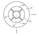
変位基板110の上面には、図2の上面図に示されているように、5枚の電極E11〜E15が形成されている。電極E11,E12はいずれもX軸に関して線対称の同一形状を有し、両者は互いにY軸に関して線対称となる位置に配置されている。一方、電極E13,E14はいずれもY軸に関して線対称の同一形状を有し、両者は互いにX軸に関して線対称となる位置に配置されている。また、電極E15は、その中心がZ軸上に位置する円盤状の電極である。この5枚の電極E11〜E15は、変位基板110とともに変位する電極であり、以下、変位電極と呼ぶことにする。
【0023】
一方、固定基板120の下面には、図3の下面図に示されているように、5枚の電極E21〜E25が形成されている。これらの電極は固定基板120側に固定された電極であるため、以下、固定電極と呼ぶ。5枚の固定電極E21〜E25は、それぞれ5枚の変位電極E11〜E25と同じ形状の電極であり、各変位電極に対して鏡像関係の位置に配置されている。したがって、変位電極E11〜E15とこれに対向する固定電極E21〜E25とによって、5組の容量素子が形成されることになる。ここでは、電極対E11,E21からなる容量素子を第1の容量素子C1と呼び、電極対E12,E22からなる容量素子を第2の容量素子C2と呼び、電極対E13,E23からなる容量素子を第3の容量素子C3と呼び、電極対E14,E24からなる容量素子を第4の容量素子C4と呼び、電極対E15,E25からなる容量素子を第5の容量素子C5と呼ぶことにする。
【0024】
§2. 角速度の検出原理
ここで述べる実施形態の角速度センサは、装置全体に作用するX軸まわりの角速度ωxとY軸まわりの角速度ωyとを同時に検出することができる二軸角速度センサである。たとえば、振動子130をZ軸方向に振動させた状態において、この装置筐体140に対してY軸まわりの角速度ωyが作用すると、X軸方向にコリオリ力Fxが作用する(振動子130の質量をm、速度をVzとすると、作用するコリオリ力Fxは、Fx=2・m・Vz・ωyとなる)。したがって、このコリオリ力Fxを検出することができれば、Y軸まわりの角速度ωyを間接的に求めることができる。X軸上に配置された第1の容量素子C1と第2の容量素子C2とは、このX軸方向のコリオリ力Fxを検出する機能を有する。ここで、YZ平面(変位基板110に垂直で、かつ、振動子130の重心GとY軸とを含む平面)を考えると、第1の容量素子C1は、このYZ平面の第1の側に位置し、第2の容量素子C2は、このYZ平面の第2の側に位置する。このように、X軸方向のコリオリ力Fxを効率良く検出するためには、YZ平面のそれぞれ反対側に、かつ対称となる位置に配置された一対の容量素子C1,C2を用いるのが好ましい。
【0025】
また、振動子130をZ軸方向に振動させた状態において、装置筐体140に対してX軸まわりの角速度ωxが作用すると、Y軸方向にコリオリ力Fyが作用する。したがって、このコリオリ力Fyを検出することができれば、X軸まわりの角速度ωxを間接的に求めることができる。Y軸上に配置された第3の容量素子C3と第4の容量素子C4とは、このY軸方向のコリオリ力Fyを検出する機能を有する。ここで、XZ平面(変位基板110に垂直で、かつ、振動子130の重心GとX軸とを含む平面)を考えると、第3の容量素子C3は、このXZ平面の第1の側に位置し、第4の容量素子C4は、このXZ平面の第2の側に位置する。このように、Y軸方向のコリオリ力Fyを効率良く検出するためには、XZ平面のそれぞれ反対側に、かつ対称となる位置に配置された一対の容量素子C3,C4を用いるのが好ましい。
【0026】
上述したように、各容量素子C1〜C4はいずれもコリオリ力の検出に用いられる検出用容量素子であるのに対し、第5の容量素子C5は振動子130をZ軸方向に振動させるために用いられる駆動用容量素子である。ここでは、この駆動用容量素子C5を用いて、振動子130を振動させる原理を説明しよう。いま、図4の側断面図に示すように、変位電極E15に正電荷を供給し、固定電極E25に負電荷を供給した場合を考えよう(電荷の極性をそれぞれ逆にしてもよい)。このように、対向する一対の電極にそれぞれ異なる電荷を供給すると、両者間にクーロン力が作用し、両電極間に引力が働くことになる。ここで、固定基板120は剛性をもった基板であるのに対し、変位基板110は可撓性をもった基板であるため、このクーロン引力により、図4に示されているように、変位基板110が撓み(弾性変形)を生じ、変位電極E15が固定電極E25へ接近することになる。別言すれば、振動子130はZ軸正方向に速度+Vzをもって運動することになる。
【0027】
このように、振動子130がZ軸正方向に移動中に、変位電極E15および固定電極E25への電荷供給を中止すると、クーロン引力は消滅する。すると、変位基板110のもつ弾性変形に対する復元力により、振動子130はZ軸負方向に速度−Vzをもって運動することになる。このとき、振動子130の重心Gは、もとの原点Oの位置(図1に示す静止状態の位置)を通り越し、図5の側断面図に示されているように、更に下方へと運動を続けることになる。
【0028】
そこで、図6に示すように、周期φをもった交流駆動信号Uを変位電極E15と固定電極E25との間に供給すれば、振動子130は周期φをもってZ軸方向に振動することになる。実際には、たとえば、固定電極E25を接地し、変位電極E15に対して、図6に示すような交流駆動信号Uを供給すればよい。もっとも、交流駆動信号Uによってエネルギーが供給されている期間は、周期φの前半期間t1のみであり、後半期間t2には、何らエネルギー供給は行われていないので、振動子130の振動は、原点O(静止状態にあるときの重心Gの位置)を中心とした単振動にはならない。すなわち、Z軸正方向への運動は、クーロン力によってZ軸正方向に積極的に吸引することにより得られる運動であるのに対し、Z軸負方向への運動は、Z軸負方向に積極的に吸引することにより得られる運動ではなく、変位基板110の復元力に基づく運動である。このため、原点Oの位置を基準としたとき、Z軸正方向の振幅とZ軸負方向の振幅とは、必ずしも等価にはならない。しかしながら、中心位置が原点Oよりやや上方へ移動するものの、振動子130の上下運動はほぼ単振動となり、実用上は問題はない。もちろん、周期φの後半期間t2において、Z軸負方向へのクーロン力を作用させるような機構を付加すれば、原点Oを中心とした単振動を行わせることは可能であるが、構造はより複雑にならざるを得ない。
【0029】
結局、このような交流駆動信号Uを駆動用容量素子C5に供給することにより、振動子130は、図6に示すような速度Vzをもって、周期φでZ軸の正負両方向に運動することになる(実際には、速度Vzは、図示のような鋸歯状波ではなく、正弦波に近いなだらかな波形になると予想されるが、ここでは説明の便宜上、図示のような単純な波形を示す)。速度Vz=0の時点は、振動子130が最大振幅位置(最上点もしくは最下点位置)に到達した時点に相当する。図6の期間Pは、速度Vzが正の値をとる第1の期間P1と、負の値をとる第2の期間P2とが交互に現れることを示しており、各期間P1,P2は、周期φの半分の長さをもった期間になる。別言すれば、第1の期間P1は、図4に示すように、振動子130が図の上方へと運動している期間であり、第2の期間P2は、図5に示すように、振動子130が図の下方へと運動している期間である。
【0030】
このように、振動子130がZ軸に沿って振動している限りでは、変位基板110と固定基板120とは平行な関係を維持している。すなわち、図4に示す状態では、両基板の間隔は小さくなり、図5に示す状態では、両基板の間隔は大きくなるが、両基板が平行であるという関係は維持されている。ところが、Y軸まわりの角速度ωyが作用している状態では、X軸方向のコリオリ力が発生するため、この両基板の平行状態は維持されなくなる。たとえば、図7の側断面図に示すように、装置筐体140に対してY軸まわりの角速度ωyが作用していた状態において、振動子130が速度+Vzで図の上方へ運動すると、X軸正方向のコリオリ力+Fxが発生することになる。振動子130に対して、このようなコリオリ力+Fxが作用すると、変位基板110には図示のような撓みが生じ、振動子130は図示のように傾斜することになる。その結果、通常の状態(角速度が作用していない状態)に比べると、第1の容量素子C1を構成する一対の電極E11,E12の電極間隔は小さくなり、逆に、第2の容量素子C2を構成する一対の電極E12,E22の電極間隔は大きくなる。別言すれば、角速度ωyの作用により、第1の容量素子C1の静電容量値は大きくなり、第2の容量素子C2の静電容量値は小さくなる。
【0031】
ところが、図8の側断面図に示すように、振動子130が速度−Vzで図の下方へ運動すると、運動方向が逆転したために、作用するコリオリ力の方向も逆転することになり、X軸負方向のコリオリ力−Fxが発生することになる。振動子130に対して、このようなコリオリ力−Fxが作用すると、変位基板110には図8に示すような撓みが生じ、振動子130は図7とは逆の方向に傾斜することになる。その結果、通常の状態(角速度が作用していない状態)に比べると、第1の容量素子C1を構成する一対の電極E11,E12の電極間隔は大きくなり、逆に、第2の容量素子C2を構成する一対の電極E12,E22の電極間隔は小さくなる。別言すれば、角速度ωyの作用により、第1の容量素子C1の静電容量値は小さくなり、第2の容量素子C2の静電容量値は大きくなる。
【0032】
ここで注意すべき点は、上述の議論で、各容量素子の静電容量値が「大きくなる」、あるいは「小さくなる」という表現は、あくまでも角速度ωyが作用していない通常の状態と、角速度ωyが作用したときの状態とを比較した表現である。すなわち、振動子130を振動させた状態においては、角速度が何ら作用していなくても、各容量素子の電極間隔は周期φで狭くなったり広くなったり、周期的に変化を繰り返している。たとえば、図4に示すように、振動子130が図の上方へと移動した時点では、各容量素子の電極間隔は狭くなり、静電容量値は大きくなるのに対し、図5に示すように、振動子130が図の下方へと移動した時点では、各容量素子の電極間隔は広くなり、静電容量値は小さくなる。このように、各容量素子の静電容量値は、周期φで絶えず変化していることになる。
【0033】
結局、各容量素子の静電容量値の変化分には、振動子130の振動に起因する要素と、角速度の作用に起因する要素とが含まれていることになる。本発明に係る角速度センサでは、次の§3で述べる信号処理回路を採用することにより、角速度の作用に起因する要素のみを抽出することができる。
【0034】
§3. 角速度を検出するための信号処理回路
図9は、本発明に係る角速度センサに用いる信号処理回路の一部を示す回路図である。この回路図で、可変容量素子C1,C2は、それぞれ上述したセンサ本体部における第1の容量素子C1および第2の容量素子C2に相当する。実際には、この例では、図9の容量素子C1の接地側の電極が固定電極E21であり、抵抗素子R1に接続されている電極が変位電極E11である。同様に、図9の容量素子C2の接地側の電極が固定電極E22であり、抵抗素子R2に接続されている電極が変位電極E12である。ここで、容量素子C1および抵抗素子R1により第1の遅延回路が構成され、容量素子C2および抵抗素子R2により第2の遅延回路が構成されており、抵抗素子R1の抵抗値と抵抗素子R2の抵抗値は互いに等しい。
【0035】
ここで、図の入力端子T1に周期φをもった第1の周期信号φ1を与えると、第1の遅延回路(R1,C1)からは第1の遅延信号D1が出力され、図の入力端子T2に周期φをもった第2の周期信号φ2を与えると、第2の遅延回路(R2,C2)からは第2の遅延信号D2が出力されることになる。これら一対の遅延信号D1,D2は、排他的論理和演算を行う論理素子L1に与えられ、両遅延信号D1,D2の位相差を示す位相差信号Aが出力端子T3に得られる。
【0036】
いま、この図9に示す回路に対して、図10に示すような第1の周期信号φ1および第2の周期信号φ2を与えた場合を考える。ここで、第1の周期信号φ1は、周期φをもったデューティ比50%の矩形波信号である。また、第2の周期信号φ2は、同じく周期φをもったデューティ比50%の矩形波信号であるが、第1の周期信号φ1に対して所定の位相差pをもった信号である。ここでは、位相差p=π/2(周期φの1/4)に設定している。
【0037】
第1の遅延信号D1および第2の遅延信号D2は、それぞれ第1の周期信号φ1および第2の周期信号φ2を遅延させて得られる信号であるから、遅延時間をそれぞれd1,d2とすれば、図10に示すような信号になる。なお、実際には、CR遅延回路を通った遅延信号は、波形になまりが生じることになるが、本願の波形図では、説明の便宜上、各信号をなまりのない状態で示すことにする。
【0038】
さて、ここではまず、角速度が作用していない通常の状態におけるこの信号処理回路の動作を考えてみる。いま、振動子130をZ軸方向に周期φで振動させると、容量素子C1,C2を構成する一対の電極の間隔は、大きくなったり小さくなったりするので、容量素子C1,C2の静電容量値は周期φで変化することになる。しかしながら、既に述べたように、角速度が作用していない状態では、振動子130は傾斜することなしに振動するので、容量素子C1の静電容量値と容量素子C2の静電容量値とはどの瞬間においても互いに等しくなる。このため、図9に示す回路図における第1の遅延回路(R1,C1)による遅延時間d1と、第2の遅延回路(R2,C2)による遅延時間d2とは等しくなる。したがって、第1の遅延信号D1と第2の遅延信号D2との間には、第1の周期信号φ1と第2の周期信号φ2との位相差p(この例の場合、p=π/2)がそのまま維持され、位相差信号Aとしては、図10に示すように、期間t10もしくは期間t20に相当するパルス幅をもったパルス信号が得られる。ここで、期間t10=t20であり、これは位相差pに相当する期間になる。
【0039】
図10のタイミングチャートの位相差信号Aにおける期間t10は、奇数番目のパルスの期間を示し、期間t20は、偶数番目のパルスの期間を示している(ここでは、便宜上、第1の周期信号φ1の最初の立上がりエッジ部分を起点として、それ以後に最初に現れるパルスを奇数番目のパルスとして数えることにする)。このように、角速度が作用していない状態では、t10=t20となる。ここではこのパルス幅を基準幅と呼ぶことにする。ところが、Y軸まわりの角速度ωyが作用した環境下では、位相差信号Aに含まれるパルスのパルス幅が、この基準幅から外れることになる。別言すれば、第1の遅延信号D1と第2の遅延信号D2との位相差が、角速度ωyの作用により変化することになる。その理由は、§2で述べた検出原理を考慮すれば、容易に理解できよう。すなわち、角速度ωyが作用すると、図7あるいは図8に示すように、振動子130が傾斜するため、容量素子C1の静電容量値と容量素子C2の静電容量値との間に差が生じることになり、第1の遅延回路(R1,C1)による遅延時間d1と、第2の遅延回路(R2,C2)による遅延時間d2とに差が生じるからである。
【0040】
ここでは、図11に示すタイミングチャートを参照しながら、角速度ωyが作用している環境下でのこの信号処理回路の動作を説明しよう。既に述べたように、駆動用容量素子C5に対し、周期φをもった交流駆動信号Uを供給すると、振動子130はZ軸方向の速度VzをもってZ軸方向に振動することになる。このとき、図11に期間Pとして示すように、速度Vzが正の値をとる第1の期間P1と、負の値をとる第2の期間P2とが交互に現れることになるが、第1の期間P1では、図7に示すように振動子130が傾斜し、第2の期間P2では、図8に示すように振動子130が傾斜する。このように、振動子130を振動させた状態において、図9に示す回路に第1の周期信号φ1および第2の周期信号φ2を供給すると、図11に示すような第1の遅延信号D1および第2の遅延信号D2が得られることになる。
【0041】
ここで、図11に示す第1の遅延信号D1の立上がりエッジの遅延時間d11は、図10に示す遅延時間d1よりも大きくなり、逆に、立ち下がりエッジの遅延時間d12は、図10に示す遅延時間d1よりも小さくなる。これは、遅延時間d11は第1の期間P1に得られる遅延時間であるのに対し、遅延時間d12は第2の期間P2に得られる遅延時間であるためである。すなわち、第1の期間P1では、図7に示すように振動子130が傾斜するため、容量素子C1の容量値は、振動子130が傾斜しない状態(すなわち、角速度が作用していない状態)に比べて大きくなり、遅延時間d11はd1よりも大きくなる。逆に、第2の期間P2では、図8に示すように振動子130が傾斜するため、容量素子C1の容量値は、振動子130が傾斜しない状態(すなわち、角速度が作用していない状態)に比べて小さくなり、遅延時間d12はd1よりも小さくなる。
【0042】
一方、図11に示す第2の遅延信号D2の立上がりエッジの遅延時間d21は、図10に示す遅延時間d2よりも小さくなり、逆に、立ち下がりエッジの遅延時間d22は、図10に示す遅延時間d2よりも大きくなる。これは、遅延時間d21は第1の期間P1に得られる遅延時間であるのに対し、遅延時間d22は第2の期間P2に得られる遅延時間であるためである。すなわち、第1の期間P1では、図7に示すように振動子130が傾斜するため、容量素子C2の容量値は、振動子130が傾斜しない状態(すなわち、角速度が作用していない状態)に比べて小さくなり、遅延時間d21はd2よりも小さくなる。逆に、第2の期間P2では、図8に示すように振動子130が傾斜するため、容量素子C2の容量値は、振動子130が傾斜しない状態(すなわち、角速度が作用していない状態)に比べて大きくなり、遅延時間d22はd2よりも大きくなる。
【0043】
このように、角速度ωyの作用により、両周期信号の遅延時間に変化が生じると、位相差信号Aとしては、図11に示すように、期間t11もしくは期間t21に相当するパルス幅をもったパルス信号になる。ここで、一点鎖線で示すパルスは、図10に示した期間t10=t20と同じパルス幅、すなわち標準幅をもったパルスを示すものである。この図11のタイミングチャートの位相差信号Aにおける期間t11は、奇数番目のパルスの期間を示し、期間t21は、偶数番目のパルスの期間を示している。このように、本発明に係る信号処理回路では、奇数番目のパルスと偶数番目のパルスとで、異なる挙動をとることは注目すべきである。すなわち、この例では、奇数番目のパルスは、パルス幅がいずれも基準幅より小さくなっているのに対し、偶数番目のパルスは、パルス幅がいずれも基準幅より大きくなっている。
【0044】
ここで、実際のパルス幅と基準幅との差は、作用した角速度ωyの大きさに対応する。すなわち、大きな角速度が作用すれば、それだけ大きなコリオリ力が作用し、振動子130は大きく傾斜するので、静電容量値は大きく変化し、遅延時間も大きく変化することになる。また、作用する角速度ωyの向き(右まわりか、左まわりか)は、実際のパルス幅が基準幅より大きくなるか、小さくなるか、を決定する要因となる。すなわち、図7あるいは図8の例では、図において左まわりの矢印で示す角速度ωyが作用した場合を示したが、逆に、右まわりの矢印で示す角速度−ωyが作用した場合には(本出願では、図において左まわりの角速度を正、右まわりの角速度を負と便宜上定義している)、コリオリ力の方向が逆転し、これまで述べてきた現象と逆の現象が起こることになる。その結果、図11に示す位相差信号Aとは逆に、奇数番目のパルスは、パルス幅が基準幅より大きくなり、偶数番目のパルスは、パルス幅が基準幅より小さくなる。
【0045】
このように、位相差信号Aに含まれる1つのパルスのパルス幅を測定し、交流駆動信号φとの位相関係に基づいて、この1つのパルスが奇数番目のパルスか偶数番目のパルスかを特定し、測定したパルス幅を基準幅と比較することにより、瞬時の角速度ωyの向きと大きさとを認識することができる。したがって、時系列で得られるパルスのパルス幅を次々と測定してゆけば、角速度の値を連続的に得ることができる。また、パルス幅の積算値を求めるようにすれば、ある程度の期間内の平均的な角速度値を得ることができる。
【0046】
ただ、位相差信号Aに含まれる奇数番目のパルスと偶数番目のパルスとは、互いに異なる挙動をとるため、別個の取り扱いをする必要がある。たとえば積算値を求める場合、全パルスについてのパルス幅をそのまま積算してしまうと正しい結果は得られない。すなわち、図11に示す位相差信号Aの全パルスについてのパルス幅を積算すると、基準幅よりも小さなパルス幅をもった奇数番目のパルスと基準幅よりも大きなパルス幅をもった偶数番目のパルスとが相殺されてしまう。そこで、位相差信号Aを周期φ/2ごとの期間に区切り、奇数番目のパルスが存在する奇数番目の期間と、偶数番目のパルスが存在する偶数番目の期間とを定義し、奇数番目のパルスについてのパルス幅と偶数番目のパルスについてのパルス幅とを別個独立して求めるようにすればよい。
【0047】
たとえば、図11に示すように、第3の周期信号φ3を用意する。この第3の周期信号φ3は、周期φをもつデューティー比50%の矩形波信号であるが、図にハッチングを施したハイレベルの区間に、位相差信号Aの奇数番目のパルス(期間t11のパルス幅をもつパルス)が含まれるように位相を調整した信号である。たとえば、試作用のセンサ本体部と試作用の回路とを用いて、位相差信号Aを実験的に求め、この位相差信号Aに含まれる奇数番目のパルスの中心位置が、第3の周期信号φ3のハイレベル区間の中心位置に一致するように、位相差の調整を行うようにすればよい。そして、この第3の周期信号φ3と、位相差信号Aとの論理積に相当する信号を求めれば、この信号には、奇数番目のパルスのみが含まれることになるので、奇数番目のパルスのパルス幅のみを選択的に取り出すことが可能になる。逆に、図11に示すように、第3の周期信号φ3に対して論理反転状態にある第4の周期信号φ3*を用意し、この第4の周期信号φ3*と、位相差信号Aとの論理積に相当する信号を求めれば、この信号には、偶数番目のパルスのみが含まれることになるので、偶数番目のパルスのパルス幅のみを選択的に取り出すことが可能になる。
【0048】
なお、パルス幅を積算するには、たとえば、選択的に取り出した一方のパルスを含んだ信号を平滑用コンデンサに与えて平滑化し、アナログ電圧値として積算値を得る手法を採ることもできるし、あるいは、周期φに対して十分に短い周期で動作するカウンタによりパルス幅をカウントし、デジタルカウント値として積算値を得る手法を採ることもできる。
【0049】
こうして得られた奇数番目のパルスについてのパルス幅も、偶数番目のパルスについてのパルス幅も、いずれも角速度ωyの向きおよび大きさに関する情報を有している。すなわち、前者は、図11に示す位相差信号Aの期間t11に相当するものであるから、標準幅よりも小さければ、左まわりの角速度ωyの作用を示し、標準幅よりも大きければ、右まわりの角速度−ωyの作用を示すことになる。逆に、後者は、図11に示す位相差信号Aの期間t21に相当するものであるから、標準幅よりも大きければ、左まわりの角速度ωyの作用を示し、標準幅よりも小さければ、右まわりの角速度−ωyの作用を示すことになる。また、いずれの場合も、標準幅と実際のパルス幅との差が、作用した角速度の大きさを示すことになる。
【0050】
このように、奇数番目のパルスについてのパルス幅も、偶数番目のパルスについてのパルス幅も、いずれも角速度ωyの向きおよび大きさに関する情報を有しているので、原理的には、いずれか一方だけを用いて角速度の検出が可能である。しかしながら、精度の高い検出値を得る上では、両方のパルス幅をともに利用するのが好ましい。そのためには、奇数番目のパルスについてのパルス幅と、偶数番目のパルスについてのパルス幅との差をとるようにすればよい。同じ角速度が作用した場合、奇数番目のパルスと偶数番目のパルスとは、一方のパルス幅が大きくなると、他方のパルス幅は小さくなるという相補的な挙動をとるため、両者の差をとることにより、両方をともに利用した検出が可能になる。このように、奇数番目のパルスと偶数番目のパルスとの双方を利用した検出を行うことができる、より実用的な信号処理回路を以下に述べる。
【0051】
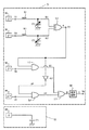
§4. 角速度を検出するための実用的な信号処理回路
図12は、本発明に係る角速度センサに用いる実用的な信号処理回路を示す回路図である。この信号処理回路は、検出用回路71と駆動用回路72とによって構成されている。検出用回路71は、図1に示すセンサ本体部を用いて、Y軸まわりに作用する角速度ωyを検出するための回路であり、駆動用回路72は、そのような検出を行う際に、振動子130をZ軸方向に振動させるための駆動を行う回路である。
【0052】
ここで、検出用回路71の上段に示された抵抗素子R1,R2、容量素子C1,C2、排他的論理和演算を行う論理回路L1は、図9に示した回路の各構成要素と全く同じものである。また、第1の信号供給回路10は、第1の周期信号φ1を発生させる回路を示しており、第2の信号供給回路20は、第2の周期信号φ2を発生させる回路を示している。この信号処理回路では、更に、第3の周期信号φ3を発生させて入力端子T4に与える第3の信号供給回路30と、第4の周期信号φ3*を発生させて入力端子T5に与える第4の信号供給回路40とが設けられている。ここで、第3の周期信号φ3,第4の周期信号φ3*は、図11のタイミングチャートに示された各信号である。
【0053】
論理回路L2は、出力端子T3に得られた位相差信号Aと、入力端子T4に与えられた第3の周期信号φ3との論理積演算を行い、出力信号A1を得る回路である。また、論理回路L3は、出力端子T3に得られた位相差信号Aを論理反転し、反転位相差信号A*を求める回路であり、論理回路L4は、この反転位相差信号A*と、入力端子T5に与えられた第4の周期信号φ3*との論理積演算を行い、出力信号A2を得る回路である。更に、論理回路L5は、出力信号A1と出力信号A2との論理和演算を行い、出力信号Bを求める回路であり、その後段に接続された積算回路50は、出力信号Bに含まれる全パルスのパルス幅を積算し、積算値を示す出力信号Cを出力する回路である。かくして、出力端子T6には、所定の積算値を示す出力信号Cが得られることになる。
【0054】
一方、駆動用回路72は、実質的に、駆動信号供給回路60によって構成される回路である。この駆動信号供給回路60は、駆動用容量素子C5に対して供給する交流駆動信号Uを発生させる回路である。交流駆動信号Uは、既に述べたように、周期φをもった周期信号であり、この交流駆動信号Uを第5の容量素子C5に供給することにより、振動子130をZ軸方向に振動させることができる。
【0055】
さて、この図12に示す信号処理回路の動作を図13のタイミングチャートに基づいて説明しよう。この回路の出力端子T3に、図13に示すような位相差信号Aが得られることは既に§3で述べたとおりである。ここで、一点鎖線で示すパルスは、角速度が作用していない状態で得られる標準幅をもったパルスである。この例では、左まわりの角速度ωyの作用により、奇数番目のパルスのパルス幅(期間t11)は標準幅より小さくなり、偶数番目のパルスのパルス幅(期間t21)は標準幅より大きくなっている。論理回路L2では、この位相差信号Aと第3の周期信号φ3との論理積演算が行われ、出力信号A1が得られる。出力信号A1は、位相差信号A内の奇数番目のパルスのみを抽出した信号になる。一方、論理回路L3で反転された反転位相差信号A*の波形と、入力端子T5に与えられる第4の周期信号φ3*の波形とは、図13に示すとおりになり、論理回路L4の出力信号A2は、図示のように、所定の期間t21*に相当するパルス幅をもったパルスになる。ここで、期間t21と期間t21*とは、相補的な関係にある。すなわち、t21+2・t21*=φ/2(半周期)の関係にあるので、期間t21が大きくなれば、期間t21*は小さくなり、期間t21が小さくなれば、期間t21*は大きくなる。
【0056】
論理回路L5では、信号A1と信号A2との論理和信号Bが得られるが、この論理和信号Bは、図13に示すように、期間t11(奇数番目のパルスのパルス幅)をもったパルスと、期間t21*(偶数番目のパルスのパルス幅に対して相補的な値)をもったパルスと、を含む信号になる。このため、論理和信号Bに含まれる全パルスのパルス幅の積算値Sは、位相差信号Aの奇数番目のパルスについての積算値と、偶数番目のパルスについての積算値との差に相当する値になる。積算回路50は、この積算値Sを示す出力信号Cを出力端子T6に与える。積算値Sは、図13の最下段に示すハッチング部分の面積の合計に相当する。
【0057】
この積算値Sと角速度ωyとの間には、たとえば、図14のグラフに示すような関係がある。なお、図14では、説明の便宜上、両者間の線形関係を示すグラフを示したが、実際には、両者間の関係は必ずしも線形関係にはならない。しかしながら、両者の関係は必ず単調増加(あるいは単調減少)関数となり、積算値Sと角速度ωyとの間には、必ず1対1の対応関係が得られる。したがって、積算値Sが特定されれば、必ず角速度ωyの値が特定されることになる。図14に示す線形関係のグラフの場合、積算値Sが基準積算値S0(角速度のない状態で得られる標準幅をもったパルスについての積算値)をとる場合には、Y軸まわりの角速度ωy=0であることを示しており、基準積算値S0よりも大きな積算値S0+ΔSをとる場合には、Y軸まわりの角速度ωyが正の値(たとえば左まわり)であることを示し、基準積算値S0よりも小さな積算値S0−ΔSをとる場合には、Y軸まわりの角速度ωyが負の値(たとえば右まわり)であることを示している。
【0058】
なお、第1の周期信号φ1と第2の周期信号φ2との間に所定の位相差pを設定する理由は、基準積算値S0を零でない所定の値に設定するためである。すなわち、位相差p=0に設定すると、基準積算値S0=0となってしまい、角速度の向き(右まわりか、左まわりか)について正しい情報を得ることができなくなる。位相差pを予め設けておけば、基準積算値S0を零でない所定の値に設定することができ、実際に得られた積算値Sが、この基準積算値S0より大きいか、小さいか、という情報により、作用した角速度の向きを認識することができ、実際に得られた積算値Sと基準積算値S0との差ΔSにより、作用した角速度の大きさを認識することができるのである。ΔSがある程度大きくなっても、角速度の向きを正しく認識できるようにするためには、基準積算値S0をできるだけ大きな値に設定するのが好ましい。そのためには、位相差p=π/2に設定するのが最も好ましい。
【0059】
§5. その他の実施形態
以上、本発明を図示する基本的な実施形態に基づいて説明したが、ここでは、本発明の別な実施形態をいくつか述べておく。
【0060】
(1) 角速度ωxの検出
これまで、図1に示す構造をもったセンサ本体部を用いて、Y軸まわりに作用した角速度ωyを検出するための信号処理回路を述べてきたが、この図1に示す角速度センサは、Y軸まわりの角速度ωyとともに、X軸まわりの角速度ωxを検出する機能を有する。Y軸まわりの角速度ωyは、質量mの振動子130を速度VzでZ軸方向に振動させながら、X軸方向に作用するコリオリ力Fx(Fx=2・m・Vz・ωy)を測定すれば求めることができた。同様に、X軸まわりの角速度ωxは、質量mの振動子130を速度VzでZ軸方向に振動させながら、Y軸方向に作用するコリオリ力Fy(Fy=2・m・Vz・ωx)を測定すればよい。
【0061】
図12の検出用回路71は、X軸上に配置された第1の容量素子C1および第2の容量素子C2を組み込んだ信号処理回路であり、出力端子T6には、コリオリ力Fxに基づく角速度ωyの検出値が得られた。そこで、この検出用回路71と全く同じ回路を用意し、第1の容量素子C1および第2の容量素子C2の部分を、それぞれ第3の容量素子C3および第4の容量素子C4に置き換えれば、出力端子T6には、コリオリ力Fyに基づく角速度ωxの検出値が得られることになる。ここでは、このように、検出用回路71におけるC1,C2を、C3,C4に置き換えた回路を検出用回路73と呼ぶことにする。
【0062】
図1に示すセンサ本体部は、本来、角速度ωx,ωyを同時に検出することができる構造をもっている。すなわち、図2および図3に示す各電極のうち、電極E15,E25(容量素子C5)は、振動子130をZ軸方向に振動させるために用いられ、電極E11,E21(容量素子C1)および電極E12,E22(容量素子C2)はコリオリ力Fxに基づいて角速度ωyを検出するために用いられ、電極E13,E23(容量素子C3)および電極E14,E24(容量素子C4)はコリオリ力Fyに基づいて角速度ωxを検出するために用いられる。したがって、このセンサ本体部に二軸角速度センサとしての機能をもたせるためには、図12に示す検出用回路71および駆動用回路72の他に、上述した検出用回路73を用意しておけばよい。駆動用回路72を用いて振動子130をZ軸方向に振動させれば、検出用回路71の出力端子T6には、角速度ωyが得られ、検出用回路73の出力端子T6には、角速度ωxが得られることになる。
【0063】
(2) 単一の容量素子を用いた検出
これまで述べてきた例では、1つの軸まわりの角速度検出に、一対の容量素子を用いている。たとえば、角速度ωyの検出には、容量素子C1,C2が用いられ、角速度ωxの検出には、容量素子C3,C4が用いられる。このように一対の容量素子を用いる形態は、単一の容量素子を用いる形態に比べて検出精度を高めることができるので、実用上は好ましい実施形態である。しかしながら、本発明の技術思想は、一対の容量素子を用いた形態に限定されるものではない。ここでは、参考のために、単一の容量素子を用いた場合でも、角速度の検出が可能なことを示しておく。
【0064】
たとえば、単一の容量素子C1のみを用いても、角速度ωyの検出が可能なことを示そう。この場合、容量素子C2は不要になるが、その代わりに、所定の固定容量をもった固定容量素子C0を用いるようにすればよい。すなわち、図12に示す検出用回路71において、容量素子C2を固定容量素子C0に置き換えればよい。容量素子C2は、図1に示すセンサ本体部の電極E12,E22によって構成される可変容量素子であったが、ここで用いる固定容量素子C0は、静電容量値が固定の素子であり、どこに設けてもかまわない。たとえば、検出用回路71を実装するための回路基板上に、コンデンサ素子として設けておけば十分である。
【0065】
いま、図7に示すように、振動子130が速度+Vzをもって運動中に、角速度ωyが作用したときの状態を考えると、既に述べたように、コリオリ力+Fxの作用により、容量素子C1の電極間隔は、角速度ωyが作用していなかった場合に比べて小さくなる。同様に、図8に示すように、振動子130が速度−Vzをもって運動中に、角速度ωyが作用したときの状態を考えると、既に述べたように、コリオリ力−Fxの作用により、容量素子C1の電極間隔は、角速度ωyが作用していなかった場合に比べて大きくなる。このように、単一の容量素子C1にのみ着目しても、やはりコリオリ力の作用による静電容量値の変化は生じているのである。したがって、単一の容量素子C1のみを用いた場合でも、図11に示すタイミングチャートにおいて、遅延信号D1が得られることには変わりはない。
【0066】
ただ、可変容量素子C2の代わりに、固定容量素子C0を用いた場合、もう一方の遅延信号D2は、図11のタイミングチャートに示すものとは若干異なってくる。すなわち、静電容量値が固定であるため、周期信号φ2を常に一定の遅延時間だけ遅らせた固定の信号になる。しかしながら、遅延信号D1は角速度の作用に応じて変化する信号であるため、両者の位相差を示す位相差信号Aには、角速度の作用を示す信号成分が含まれていることになり、既に述べたとおりの動作により、角速度の検出が可能である。
【0067】
(3) 別な振動態様
これまで述べた例は、電極E15,E25からなる第5の容量素子に交流駆動信号Uを与えて、振動子130をZ軸方向に振動させていたが、振動子130の振動方向は必ずしもZ軸方向に限定する必要はない。たとえば、図15に示すような2種類の交流駆動信号U1,U2(互いに位相差がπであるデューティ比50%の矩形波信号)を用意し、第1の交流駆動信号U1を第1の容量素子C1に与え、第2の交流駆動信号U2を第2の容量素子C2に与えれば、振動子130は、図示のようなX軸方向の速度成分VxをもってX軸方向に振動することになる。
【0068】
このように、振動子130をX軸方向に振動させた状態において、たとえば、容量素子C3,C4を用いてY軸方向に作用するコリオリ力Fyを検出するようにすれば、Z軸まわりの角速度ωzを検出することが可能になる。あるいは、容量素子C5および固定容量素子C0を用いてZ軸方向に作用するコリオリ力Fzを検出するようにすれば、Y軸まわりの角速度ωyを検出することが可能になる。
【0069】
なお、いずれの振動態様をとる場合でも、振動子130を最も効率的に振動させることができる共振周波数をもった交流駆動信号Uを与え、この共振周波数で振動させるのが好ましい。共振周波数の値は、たとえば、試作品について種々の周波数の交流駆動信号を与える実験を行えば求めることができる。
【0070】
(4) センサ本体部のより実用的な構造
図1に示すセンサ本体部の構造は、本発明の一実施形態を示すものであり、この他にも種々の構造のものを用いることが可能である。たとえば、図16は、本発明に用いるセンサ本体部のより実用的な構造を示す側断面図である。可撓性をもった変位基板210の上に、固定基板220が取り付けられている。固定基板220の外周部には脚部221が形成されており、この脚部221の底面が変位基板210の上面に固着されている。したがって、変位基板210と固定基板220とは所定間隔を隔てて、平行な状態に支持されている。変位基板210の下面中央部には、振動子230が固着されている。また、この振動子230の周囲には、台座240が設けられており、この台座240によって、変位基板210はベース基板250に対して支持されている。振動子230の上方および下方には、若干の空間が確保されているため、図の上下方向への振動が可能である。
【0071】
図17は、変位基板210の上面図である。この図に示されているように、変位基板210の上面には5枚の変位電極E31〜E35が形成されている。これらは、図2に示す実施形態における変位電極E11〜E15に相当するものである。一方、図18は、固定基板220の下面図である。この固定基板220の下面には、単一の共通電極E40が形成されている。この共通電極E40は、図3に示す実施形態における固定電極E21〜E25に相当するものである。図12の回路図を見ればわかるように、実際の信号処理回路では、各容量素子C1〜C5の一方の電極はいずれも接地されることになる。したがって、一方を共通電極E40とし、この共通電極E40を接地するようにすれば、実用上は支障は生じない。むしろ、構造を単純化する上では、このように一方を共通電極にするのが好ましい。特に、固定基板220にセンサ筐体を兼ねさせるとともに、これを導電性材料で構成すれば、固定基板220自体を共通電極として用いることが可能になり、構造は更に単純化される。
【0072】
(5) 振動子の別な駆動方法
これまで述べた実施形態は、駆動用の容量素子に交流駆動信号を与えることにより、振動子を振動させていたが、振動子に振動エネルギーを供給する方法としては、どのような方法を採ってもかまわない。たとえば、図19に示す実施形態は、図16に示す実施形態において、振動子の駆動方法を磁力を利用した方法に変えた例である。すなわち、台座245の桁上げを行い、振動子230の下方に、磁場発生部300を設置するようにし、この磁場発生部300に対して、駆動信号供給回路310から周期φの交流信号を供給するようにしている。磁場発生部300としては、たとえば、一般的な電磁コイルを用いればよい。振動子230の少なくとも一部を鉄,コバルト,ニッケルなどの磁性材料によって構成しておき、磁場発生部300に周期φの交流信号に基づいた周期磁場を発生させれば、振動子230を図の上下方向に振動させることができる。この場合、駆動用の容量素子C5を構成する変位電極E35は不要になる。
【0073】
【発明の効果】
以上のとおり本発明に係る振動子を用いた角速度センサによれば、コリオリ力の作用により振動子に傾斜が生じるような構成とし、この傾斜に基づく静電容量の変化を2つの周期信号の位相差として検出するようにしたため、信号処理回路を単純化することができ、効率的な角速度検出が可能になる。
【図面の簡単な説明】
【図1】本発明の一実施形態に係る角速度センサのセンサ本体部の基本構造を示す側断面図である。
【図2】図1に示すセンサ本体部における変位基板110の上面図である。
【図3】図1に示すセンサ本体部における固定基板120の下面図である。
【図4】図1に示すセンサ本体部において、振動子130を図の上方へ運動させた状態を示す側断面図である。
【図5】図1に示すセンサ本体部において、振動子130を図の下方へ運動させた状態を示す側断面図である。
【図6】図1に示すセンサ本体部において、振動子130を図の上下方向へ振動させるために供給する交流駆動信号Uおよび振動子130の速度成分Vzの波形を示すタイミングチャートである。
【図7】図1に示すセンサ本体部において、振動子130が図の上方へ運動中に、Y軸まわりの角速度ωyに基づくX軸方向のコリオリ力+Fxが作用した状態を示す側断面図である。
【図8】図1に示すセンサ本体部において、振動子130が図の下方へ運動中に、Y軸まわりの角速度ωyに基づくX軸方向のコリオリ力−Fxが作用した状態を示す側断面図である。
【図9】本発明に係る角速度センサに用いる信号処理回路の一部を示す回路図である。
【図10】図9に示す信号処理回路の動作を説明するためのタイミングチャートである。
【図11】図9に示す信号処理回路の動作を説明するための更に別なタイミングチャートである。
【図12】本発明に係る角速度センサに用いる実用的な信号処理回路を示す回路図である。
【図13】図12に示す信号処理回路の動作を説明するためのタイミングチャートである。
【図14】図12に示す信号処理回路によって得られる積算値Sと角速度ωyとの関係を示すグラフである。
【図15】図1に示すセンサ本体部において、振動子130を図の左右方向へ振動させるために供給する交流駆動信号U1,U2および振動子130の速度成分Vxの波形を示すタイミングチャートである。
【図16】本発明に用いるセンサ本体部のより実用的な構造を示す側断面図である。
【図17】図16に示すセンサ本体部における変位基板210の上面図である。
【図18】図16に示すセンサ本体部における固定基板220の下面図である。
【図19】図16に示すセンサ本体部において、振動子の駆動方法を変えた実施形態の構造を示す側断面図である。
【符号の説明】
10〜40…信号供給回路
50…積算回路
60…駆動信号供給回路
71…検出用回路
72…駆動用回路
110…変位基板
120…固定基板
130…振動子
140…装置筐体
210…変位基板
220…固定基板
221…脚部
230…振動子
240,245…台座
250…ベース基板
300…磁場発生部
310…駆動信号供給回路
A…位相差信号
A1,A2…論理積信号
A*…反転位相差信号
B…出力信号
C…出力信号
C1〜C5…容量素子
D1,D2…遅延信号
d1,d2,d11,d12,d21,d22,t21*…遅延時間
E11〜E15…変位電極
E21〜E25…固定電極
E31〜E35…変位電極
E40…共通電極
G…重心
L1〜L5…論理素子
p…位相差
P1,P2…奇数番目の期間,偶数番目の期間
R1,R2…抵抗素子
S…積算値
S0…基準積算値
T1〜T6…入出力端子
t1,t2,t10,t11,t20,t21…期間(パルス幅)
U,U1,U2…交流駆動信号
Vx,Vz…X軸,Z軸方向の速度成分
φ1,φ2,φ3,φ3*…周期φの周期信号
ωy…Y軸まわりの角速度[0001]
BACKGROUND OF THE INVENTION
The present invention relates to an angular velocity sensor using a vibrator, and more particularly to an angular velocity sensor that detects a Coriolis force acting on a vibrator based on a change in capacitance of a capacitive element.
[0002]
[Prior art]
In the automobile industry and the machine industry, there is an increasing demand for sensors that can accurately detect the acceleration and angular velocity of a moving object. In general, an acceleration in an arbitrary direction and an angular velocity in an arbitrary rotation direction act on an object that freely moves in a three-dimensional space. For this reason, in order to accurately grasp the movement of the object, it is necessary to independently detect the acceleration in each coordinate axis direction and the angular velocity around each coordinate axis in the XYZ three-dimensional coordinate system.
[0003]
As a sensor for detecting the angular velocity, an angular velocity sensor using a vibrator has attracted attention. The basic principle of an angular velocity sensor using this vibrator is to detect the Coriolis force acting in the second axial direction when the vibrator is vibrated in the first axial direction for three axes orthogonal to each other. The angular velocity around the third axis is obtained. This utilizes the physical phenomenon that Coriolis force acts in the second axial direction when an angular velocity around the third axis acts on an object moving in the first direction. If this Coriolis force in the second axial direction is detected, the angular velocity around the third axis can be obtained indirectly.
[0004]
As an angular velocity sensor based on such a principle, for example, in International Publication No. WO94 / 23272 based on the Patent Cooperation Treaty, a Coriolis force is detected based on a change in the capacitance of a capacitive element, so that biaxial or A multi-axis angular velocity sensor capable of detecting angular velocities around three axes is disclosed. This sensor has a structure that causes a change in the electrode spacing of the capacitive element when the Coriolis force is applied. By monitoring the change in the capacitance of the capacitive element, it is possible to detect the applied angular velocity. Become.
[0005]
[Problems to be solved by the invention]
The above-described angular velocity sensor that detects the Coriolis force acting on the vibrator by using a capacitive element is suitable for mass production and commercial at a relatively low cost because the mechanical structure of the main body portion is relatively simple. Use is expected. However, the signal processing circuit portion is not sufficiently simplified as compared with the structure of the main body portion, which prevents a reduction in cost for practical use. That is, in this type of angular velocity sensor, signal processing for extracting a change in capacitance of the capacitive element as some electrical signal is indispensable, but several analog circuits for performing such signal processing have been proposed. The circuit configuration must be quite complicated.
[0006]
In addition, control technology using digital signals has become commonplace, and today, as a form of using a signal from an angular velocity sensor, a use form as a digital signal has become mainstream, and it is suitable for use as a digital signal. Realization of a simple signal processing circuit is desired.
[0007]
Therefore, an object of the present invention is to provide an angular velocity sensor using a vibrator having a simple and efficient signal processing circuit.
[0008]
[Means for Solving the Problems]
(1) According to the first aspect of the present invention, a Coriolis force acting in a second axial direction perpendicular to the first axis is detected with respect to a vibrator vibrating in the first axial direction. In an angular velocity sensor for determining an angular velocity about a third axis orthogonal to both the first axis and the second axis,
A device housing that accommodates some or all of the elements constituting the sensor;
A vibrator housed in the device housing;
Support for supporting the vibrator with a predetermined degree of freedom with respect to the apparatus housing so that it can vibrate in the first axial direction and can be tilted by the action of the Coriolis force in the second axial direction. Means,
Driving means for vibrating the vibrator in the first axial direction with a predetermined period φ;
The displacement electrode formed on the vibrator side and the fixed electrode formed on the apparatus housing side, and when a Coriolis force directed in the positive direction of the second axis is applied, the electrode spacing is caused by the inclination of the vibrator. Is reduced, and when a Coriolis force directed in the negative direction of the second axis is applied, the first capacitor element is disposed so that the electrode interval is increased by the inclination of the vibrator;
The displacement electrode formed on the vibrator side and the fixed electrode formed on the apparatus housing side, and when a Coriolis force directed in the positive direction of the second axis is applied, the electrode spacing is caused by the inclination of the vibrator. Is increased, and when a Coriolis force directed in the negative direction of the second axis is applied, the second capacitor element is arranged so that the electrode interval is reduced by the inclination of the vibrator;
A first delay circuit formed by combining a first capacitive element and a resistive element;
A second delay circuit comprising a combination of a second capacitive element and a resistive element;
A first signal supply circuit for generating a first periodic signal having a period φ and supplying the first periodic signal to the first delay circuit;
A second signal supply circuit that generates a second periodic signal having a period φ and a predetermined phase difference p with respect to the first periodic signal, and supplies the second periodic signal to the second delay circuit. When,
A phase difference detection circuit that generates a phase difference signal indicating a phase difference between the first delay signal output from the first delay circuit and the second delay signal output from the second delay circuit;
This phase difference signalCorresponds to half the period φAn angular velocity detection circuit that detects an angular velocity around the third axis based on at least one of the phase difference indicated in the odd-numbered period and the phase difference indicated in the even-numbered period, divided into periods of each period φ / 2 When,
Is provided.
[0009]
(2) According to a second aspect of the present invention, in the angular velocity sensor using the vibrator according to the first aspect described above,
Instead of using a variable capacitance element having a displacement electrode formed on the vibrator side and a fixed electrode formed on the apparatus housing side as a second capacitance element, a fixed capacitance element having a predetermined fixed capacitance is used. It is intended to be used.
[0010]
(3) According to a third aspect of the present invention, in the angular velocity sensor using the vibrator according to the first or second aspect described above,
The angular velocity detection circuit detects the angular velocity based on the difference between the phase difference indicated in the odd-numbered period and the phase difference indicated in the even-numbered period.
[0011]
(4) According to a fourth aspect of the present invention, in the angular velocity sensor using the vibrator according to the first or second aspect described above,
A phase difference detection circuit detects a phase difference by a first logic element that obtains an exclusive OR of the first delay signal and the second delay signal, and outputs a phase difference signal output from the first logic element. Show the phase difference by the pulse width,
A third signal supply circuit that generates a third periodic signal having a period φ, and a second logic element that obtains a logical product of the third periodic signal and the phase difference signal; And the second logic element separates the odd-numbered pulse and the even-numbered pulse of the phase difference signal based on at least one of the pulse width of the odd-numbered pulse and the pulse width of the even-numbered pulse. The angular velocity is detected.
[0012]
(5) According to a fifth aspect of the present invention, in the angular velocity sensor using the vibrator according to the first or second aspect described above,
A phase difference detection circuit detects a phase difference by a first logic element that obtains an exclusive OR of the first delay signal and the second delay signal, and outputs a phase difference signal output from the first logic element. Show the phase difference by the pulse width,
The angular velocity detection circuit generates a third signal that generates a third periodic signal having a period φ, and a fourth signal that generates a fourth periodic signal that is in a logically inverted state with respect to the third periodic signal. A second logic element for obtaining a logical product of the third periodic signal and the phase difference signal, and a third logic for generating an inverted phase difference signal in a logic inverted state with respect to the phase difference signal. A fourth logical element that obtains a logical product of the element, the fourth periodic signal and the inverted phase difference signal, and a logical sum of the output signal of the second logical element and the output signal of the fourth logical element. 5, and the angular velocity is detected based on the pulse width of the output signal of the fifth logic element.
[0013]
(6) According to a sixth aspect of the present invention, in the angular velocity sensor using the vibrator according to the first to fifth aspects described above,
The second signal supply circuit generates a second periodic signal having a predetermined phase difference p with respect to the first periodic signal generated by the first signal supply circuit;
The angular velocity detection circuit defines a phase difference in a state where Coriolis force is not acting as a reference value, and when the actually detected phase difference is larger than the reference value, the difference is regarded as an angular velocity related to the first rotation direction. When the detected phase difference is smaller than the reference value, the difference is output as an angular velocity related to the second rotation direction opposite to the first rotation direction.
[0014]
(7) According to a seventh aspect of the present invention, in the angular velocity sensor using the vibrator according to the first to sixth aspects described above,
A driving capacitive element composed of a displacement electrode formed on the vibrator side and a fixed electrode formed on the apparatus housing side, and a drive for supplying an AC driving signal with a period φ to the driving capacitive element to the driving means And a signal supply circuit, and the vibrator is vibrated by a Coulomb force acting in the driving capacitive element.
[0015]
(8) According to an eighth aspect of the present invention, in the angular velocity sensor using the vibrator according to the first to sixth aspects described above,
At least a part of the vibrator is made of a magnetic material,
The drive means is provided with a magnetic field generator for generating a magnetic field acting on the magnetic material portion of the vibrator, and a drive signal supply circuit for supplying an AC signal with a period φ to the magnetic field generator, and the AC signal is supplied to the magnetic field generator. The vibrator is vibrated by generating a periodic magnetic field based on the above.
[0016]
(9) According to a ninth aspect of the present invention, in the angular velocity sensor using the vibrator according to the first aspect described above,
A support means is constituted by a flexible displacement substrate in which a part is fixed to the apparatus housing and a vibrator is fixed to a part.
A fixed substrate is provided in the apparatus housing so as to face this displacement substrate, and a capacitive element is constituted by a displacement electrode formed on the displacement substrate and a fixed electrode formed on the fixed substrate. It is.
[0017]
(10) According to a tenth aspect of the present invention, in the angular velocity sensor using the vibrator according to the ninth aspect described above,
A plane perpendicular to the displacement substrate and including the center of gravity of the vibrator and the third axial direction is defined, and a first capacitive element is formed on the first side with respect to the plane, and the plane is The second capacitor element is formed on the second side opposite to the first side.
[0018]
DETAILED DESCRIPTION OF THE INVENTION
Hereinafter, the present invention will be described based on the illustrated embodiments.
[0019]
§1. Basic structure of sensor body
FIG. 1 is a side sectional view showing a basic structure of a sensor main body of an angular velocity sensor according to an embodiment of the present invention. This angular velocity sensor requires a signal processing circuit in addition to the sensor main body shown in FIG. 1, and the configuration of the signal processing circuit will be described later.
[0020]
As shown in FIG. 1, the
[0021]
Here, for convenience of explanation, the origin O is defined at the position of the center of gravity G of the
[0022]
On the upper surface of the
[0023]
On the other hand, as shown in the bottom view of FIG. 3, five electrodes E <b> 21 to E <b> 25 are formed on the lower surface of the fixed
[0024]
§2. Angular velocity detection principle
The angular velocity sensor according to the embodiment described here is a biaxial angular velocity sensor that can simultaneously detect an angular velocity ωx around the X axis and an angular velocity ωy around the Y axis acting on the entire apparatus. For example, in a state where the
[0025]
In addition, when the
[0026]
As described above, each of the capacitive elements C1 to C4 is a detection capacitive element used for detecting Coriolis force, whereas the fifth capacitive element C5 is used to vibrate the
[0027]
As described above, when the supply of electric charges to the displacement electrode E15 and the fixed electrode E25 is stopped while the
[0028]
Therefore, as shown in FIG. 6, if an AC drive signal U having a period φ is supplied between the displacement electrode E15 and the fixed electrode E25, the
[0029]
Eventually, by supplying such an AC drive signal U to the drive capacitive element C5, the
[0030]
Thus, as long as the
[0031]
However, as shown in the side sectional view of FIG. 8, when the
[0032]
It should be noted that in the above discussion, the expression that the capacitance value of each capacitive element is “increased” or “decreasing” means that the normal state where the angular velocity ωy does not act and the angular velocity It is the expression which compared with the state when (omega) y acted. That is, in the state in which the
[0033]
As a result, the change in the capacitance value of each capacitive element includes an element caused by the vibration of the
[0034]
§3. Signal processing circuit for detecting angular velocity
FIG. 9 is a circuit diagram showing a part of a signal processing circuit used in the angular velocity sensor according to the present invention. In this circuit diagram, variable capacitance elements C1 and C2 correspond to the first capacitance element C1 and the second capacitance element C2 in the sensor main body described above, respectively. Actually, in this example, the electrode on the ground side of the capacitive element C1 of FIG. 9 is the fixed electrode E21, and the electrode connected to the resistance element R1 is the displacement electrode E11. Similarly, the electrode on the ground side of the capacitive element C2 in FIG. 9 is the fixed electrode E22, and the electrode connected to the resistance element R2 is the displacement electrode E12. Here, the capacitor element C1 and the resistor element R1 constitute a first delay circuit, and the capacitor element C2 and the resistor element R2 constitute a second delay circuit. The resistance value of the resistor element R1 and the resistor element R2 The resistance values are equal to each other.
[0035]
Here, when the first period signal φ1 having the period φ is applied to the input terminal T1 in the figure, the first delay signal D1 is output from the first delay circuit (R1, C1), and the input terminal in the figure When the second period signal φ2 having the period φ is supplied to T2, the second delay signal D2 is output from the second delay circuit (R2, C2). The pair of delay signals D1 and D2 are given to the logic element L1 that performs an exclusive OR operation, and a phase difference signal A indicating the phase difference between the two delay signals D1 and D2 is obtained at the output terminal T3.
[0036]
Consider a case where the first periodic signal φ1 and the second periodic signal φ2 as shown in FIG. 10 are given to the circuit shown in FIG. Here, the first periodic signal φ1 is a rectangular wave signal having a period φ and a duty ratio of 50%. Further, the second periodic signal φ2 is a rectangular wave signal having a duty ratio of 50%, which has the same period φ, but has a predetermined frequency with respect to the first periodic signal φ1.Phase differenceIt is a signal with p. Here, the phase difference p is set to π / 2 (1/4 of the period φ).
[0037]
Since the first delay signal D1 and the second delay signal D2 are signals obtained by delaying the first periodic signal φ1 and the second periodic signal φ2, respectively, if the delay times are d1 and d2, respectively. The signal is as shown in FIG. Actually, the delayed signal that has passed through the CR delay circuit has a rounded waveform, but in the waveform diagram of the present application, for convenience of explanation, each signal is shown in a non-rounded state.
[0038]
Now, let us first consider the operation of this signal processing circuit in a normal state where no angular velocity is acting. Now, when the
[0039]
A period t10 in the phase difference signal A in the timing chart of FIG. 10 indicates an odd-numbered pulse period, and a period t20 indicates an even-numbered pulse period (here, for the sake of convenience, the first periodic signal φ1). The first rising edge portion of (1) is the starting point, and the first pulse appearing thereafter is counted as an odd-numbered pulse). Thus, in a state where the angular velocity is not acting, t10 = t20. Here, this pulse width is referred to as a reference width. However, under the environment where the angular velocity ωy around the Y axis acts, the pulse width of the pulse included in the phase difference signal A deviates from this reference width. In other words, the phase difference between the first delay signal D1 and the second delay signal D2 changes due to the action of the angular velocity ωy. The reason can be easily understood by considering the detection principle described in §2. That is, when the angular velocity ωy acts, as shown in FIG. 7 or FIG. 8, the
[0040]
Here, the operation of this signal processing circuit in an environment in which the angular velocity ωy is applied will be described with reference to the timing chart shown in FIG. As described above, when the AC drive signal U having the period φ is supplied to the driving capacitive element C5, the
[0041]
Here, the delay time d11 of the rising edge of the first delay signal D1 shown in FIG. 11 is larger than the delay time d1 shown in FIG. 10, and conversely, the delay time d12 of the falling edge is shown in FIG. It becomes smaller than the delay time d1. This is because the delay time d11 is a delay time obtained in the first period P1, while the delay time d12 is a delay time obtained in the second period P2. That is, in the first period P1, since the
[0042]
On the other hand, the rising edge delay time d21 of the second delay signal D2 shown in FIG. 11 is smaller than the delay time d2 shown in FIG. 10, and conversely, the falling edge delay time d22 is the delay shown in FIG. It becomes larger than time d2. This is because the delay time d21 is a delay time obtained in the first period P1, while the delay time d22 is a delay time obtained in the second period P2. That is, in the first period P1, the
[0043]
Thus, when the delay time of both periodic signals changes due to the action of the angular velocity ωy, the phase difference signal A is a pulse having a pulse width corresponding to the period t11 or the period t21 as shown in FIG. Become a signal. Here, the pulse indicated by the alternate long and short dash line indicates a pulse having the same pulse width as that of the period t10 = t20 shown in FIG. A period t11 in the phase difference signal A in the timing chart of FIG. 11 indicates an odd-numbered pulse period, and a period t21 indicates an even-numbered pulse period. Thus, it should be noted that the signal processing circuit according to the present invention behaves differently between the odd-numbered pulses and the even-numbered pulses. That is, in this example, the odd-numbered pulses all have a pulse width smaller than the reference width, whereas the even-numbered pulses all have a pulse width larger than the reference width.
[0044]
Here, the difference between the actual pulse width and the reference width corresponds to the magnitude of the applied angular velocity ωy. That is, if a large angular velocity is applied, a corresponding Coriolis force is applied, and the
[0045]
In this way, the pulse width of one pulse included in the phase difference signal A is measured, and whether this one pulse is an odd-numbered pulse or an even-numbered pulse is determined based on the phase relationship with the AC drive signal φ. The direction and magnitude of the instantaneous angular velocity ωy can be recognized by comparing the measured pulse width with the reference width. Therefore, if the pulse widths of the pulses obtained in time series are measured one after another, the angular velocity value can be obtained continuously. Further, if the integrated value of the pulse width is obtained, an average angular velocity value within a certain period can be obtained.
[0046]
However, since the odd-numbered pulse and the even-numbered pulse included in the phase difference signal A behave differently from each other, it is necessary to handle them separately. For example, when obtaining an integrated value, a correct result cannot be obtained if the pulse widths for all the pulses are integrated as they are. That is, when the pulse widths of all the pulses of the phase difference signal A shown in FIG. 11 are integrated, the odd-numbered pulse having a pulse width smaller than the reference width and the even-numbered pulse having a pulse width larger than the reference width. Will be offset. Therefore, the phase difference signal A is divided into periods of the period φ / 2, and an odd-numbered period in which odd-numbered pulses exist and an even-numbered period in which even-numbered pulses exist are defined, and the odd-numbered pulses And the pulse width for even-numbered pulses may be obtained separately and independently.
[0047]
For example, as shown in FIG. 11, a third periodic signal φ3 is prepared. The third periodic signal φ3 is a rectangular wave signal having a period φ and a duty ratio of 50%, but the odd-numbered pulse (phase t11 of the period t11) of the phase difference signal A is shown in the high level section hatched in the figure. This is a signal whose phase is adjusted to include a pulse having a pulse width. For example, the phase difference signal A is experimentally obtained using a prototype sensor body and a prototype circuit, and the center position of the odd-numbered pulse included in the phase difference signal A is the third periodic signal. What is necessary is just to adjust a phase difference so that it may correspond to the center position of the high level area of (phi) 3. Then, if a signal corresponding to the logical product of the third periodic signal φ3 and the phase difference signal A is obtained, only odd-numbered pulses are included in this signal. Only the pulse width can be selectively extracted. Conversely, as shown in FIG. 11, the fourth periodic signal φ3 in the logic inversion state with respect to the third periodic signal φ3.*And prepares the fourth periodic signal φ3*And a signal corresponding to the logical product of the phase difference signal A and the signal includes only even-numbered pulses, and therefore only the pulse width of even-numbered pulses is selectively extracted. Is possible.
[0048]
In addition, in order to integrate the pulse width, for example, a method including obtaining a summed value as an analog voltage value by giving a smoothing capacitor with a signal including one selectively extracted pulse can be adopted, Alternatively, a method of counting the pulse width with a counter that operates at a period sufficiently short with respect to the period φ and obtaining an integrated value as a digital count value can be adopted.
[0049]
Both the pulse width for the odd-numbered pulse thus obtained and the pulse width for the even-numbered pulse both have information on the direction and magnitude of the angular velocity ωy. That is, since the former corresponds to the period t11 of the phase difference signal A shown in FIG. 11, if it is smaller than the standard width, it shows the effect of the counterclockwise angular velocity ωy, and if it is larger than the standard width, it turns clockwise. This shows the effect of the angular velocity -ωy. On the contrary, the latter corresponds to the period t21 of the phase difference signal A shown in FIG. 11. Therefore, if it is larger than the standard width, it shows the effect of the counterclockwise angular velocity ωy. The effect of the surrounding angular velocity -ωy will be shown. In either case, the difference between the standard width and the actual pulse width indicates the magnitude of the applied angular velocity.
[0050]
As described above, both the pulse width for the odd-numbered pulse and the pulse width for the even-numbered pulse both have information on the direction and magnitude of the angular velocity ωy. It is possible to detect the angular velocity using only. However, in order to obtain a highly accurate detection value, it is preferable to use both pulse widths. For this purpose, the difference between the pulse width for odd-numbered pulses and the pulse width for even-numbered pulses may be taken. When the same angular velocity is applied, the odd-numbered pulse and the even-numbered pulse have the complementary behavior that when one pulse width increases, the other pulse width decreases. , Detection using both of them becomes possible. A more practical signal processing circuit capable of performing detection using both odd-numbered pulses and even-numbered pulses as described above will be described below.
[0051]
§4. Practical signal processing circuit for detecting angular velocity
FIG. 12 is a circuit diagram showing a practical signal processing circuit used in the angular velocity sensor according to the present invention. This signal processing circuit includes a
[0052]
Here, the resistance elements R1 and R2, the capacitive elements C1 and C2, and the logic circuit L1 that performs the exclusive OR operation shown in the upper stage of the
[0053]
The logic circuit L2 is a circuit that performs an AND operation on the phase difference signal A obtained at the output terminal T3 and the third periodic signal φ3 given to the input terminal T4 to obtain the output signal A1. Further, the logic circuit L3 logically inverts the phase difference signal A obtained at the output terminal T3, and inverts the phase difference signal A.*The logic circuit L4 receives the inverted phase difference signal A.*And a fourth periodic signal φ3 applied to the input terminal T5*Is a circuit that obtains an output signal A2. Further, the logic circuit L5 is a circuit that performs an OR operation between the output signal A1 and the output signal A2 to obtain the output signal B, and the integrating
[0054]
On the other hand, the
[0055]
Now, the operation of the signal processing circuit shown in FIG. 12 will be described based on the timing chart of FIG. As described in
[0056]
In the logic circuit L5, a logical sum signal B of the signal A1 and the signal A2 is obtained. As shown in FIG. 13, this logical sum signal B is a pulse having a period t11 (pulse width of odd-numbered pulses). And period t21*And a pulse having a value complementary to the pulse width of the even-numbered pulse. Therefore, the integrated value S of the pulse widths of all the pulses included in the logical sum signal B corresponds to the difference between the integrated value for the odd-numbered pulses of the phase difference signal A and the integrated value for the even-numbered pulses. Value. The integrating
[0057]
Between the integrated value S and the angular velocity ωy, for example, there is a relationship as shown in the graph of FIG. In FIG. 14, for convenience of explanation, a graph showing a linear relationship between the two is shown, but in reality, the relationship between the two is not necessarily a linear relationship. However, the relationship between them is always a monotonically increasing (or monotonically decreasing) function, and a one-to-one correspondence relationship is always obtained between the integrated value S and the angular velocity ωy. Therefore, if the integrated value S is specified, the value of the angular velocity ωy is always specified. In the case of the linear relationship graph shown in FIG. 14, when the integrated value S takes the reference integrated value S0 (the integrated value for a pulse having a standard width obtained without an angular velocity), the angular velocity ωy around the Y axis. = 0, and when the integrated value S0 + ΔS larger than the reference integrated value S0 is taken, it indicates that the angular velocity ωy around the Y axis is a positive value (for example, counterclockwise), and the reference integrated value When the integrated value S0−ΔS smaller than S0 is taken, it indicates that the angular velocity ωy around the Y axis is a negative value (for example, clockwise).
[0058]
The reason why the predetermined phase difference p is set between the first periodic signal φ1 and the second periodic signal φ2 is to set the reference integrated value S0 to a predetermined value that is not zero. That is, if the phase difference p = 0 is set, the reference integrated value S0 = 0, and correct information on the direction of angular velocity (clockwise or counterclockwise) cannot be obtained. If the phase difference p is provided in advance, the reference integrated value S0 can be set to a predetermined value that is not zero, and whether the actually obtained integrated value S is larger or smaller than the reference integrated value S0. The direction of the acting angular velocity can be recognized from the information, and the magnitude of the acting angular velocity can be recognized from the difference ΔS between the actually obtained integrated value S and the reference integrated value S0. In order to correctly recognize the direction of the angular velocity even when ΔS is increased to some extent, it is preferable to set the reference integrated value S0 as large as possible. For that purpose, it is most preferable to set the phase difference p = π / 2.
[0059]
§5. Other embodiments
Although the present invention has been described based on the basic embodiment shown in the drawings, some other embodiments of the present invention will be described here.
[0060]
(1) Detection of angular velocity ωx
So far, the signal processing circuit for detecting the angular velocity ωy acting around the Y-axis using the sensor main body having the structure shown in FIG. 1 has been described. The angular velocity sensor shown in FIG. It has a function of detecting the angular velocity ωx around the X axis as well as the angular velocity ωy around the axis. The angular velocity ωy around the Y-axis can be obtained by measuring the Coriolis force Fx (Fx = 2 · m · Vz · ωy) acting in the X-axis direction while vibrating the
[0061]
The
[0062]
The sensor main body shown in FIG. 1 originally has a structure that can simultaneously detect angular velocities ωx and ωy. That is, among the electrodes shown in FIGS. 2 and 3, the electrodes E15 and E25 (capacitance element C5) are used to vibrate the
[0063]
(2) Detection using a single capacitive element
In the examples described so far, a pair of capacitive elements is used for angular velocity detection around one axis. For example, the capacitive elements C1 and C2 are used for detecting the angular velocity ωy, and the capacitive elements C3 and C4 are used for detecting the angular velocity ωx. In this manner, the form using a pair of capacitive elements is a practically preferable embodiment because the detection accuracy can be improved as compared with the form using a single capacitive element. However, the technical idea of the present invention is not limited to the form using a pair of capacitive elements. Here, for reference, it is shown that angular velocity can be detected even when a single capacitive element is used.
[0064]
For example, let us show that the angular velocity ωy can be detected using only a single capacitive element C1. In this case, the capacitive element C2 is unnecessary, but instead, a fixed capacitive element C0 having a predetermined fixed capacitance may be used. That is, in the
[0065]
Now, as shown in FIG. 7, considering the state when the angular velocity ωy is applied while the
[0066]
However, when the fixed capacitive element C0 is used instead of the variable capacitive element C2, the other delayed signal D2 is slightly different from that shown in the timing chart of FIG. That is, since the capacitance value is fixed, the periodic signal φ2 is always a fixed signal delayed by a fixed delay time. However, since the delay signal D1 is a signal that changes in accordance with the action of the angular velocity, the phase difference signal A that indicates the phase difference between them includes a signal component that indicates the action of the angular velocity. The angular velocity can be detected by the operation as described above.
[0067]
(3) Alternative vibration modes
In the example described so far, the AC drive signal U is applied to the fifth capacitive element including the electrodes E15 and E25 to vibrate the
[0068]
As described above, when the
[0069]
In any of the vibration modes, it is preferable to provide an AC drive signal U having a resonance frequency that can vibrate the
[0070]
(4) More practical structure of the sensor body
The structure of the sensor body shown in FIG. 1 shows one embodiment of the present invention, and various other structures can be used. For example, FIG. 16 is a side sectional view showing a more practical structure of the sensor main body used in the present invention. A fixed
[0071]
FIG. 17 is a top view of the
[0072]
(5) Alternative drive method
In the embodiments described so far, the vibrator is vibrated by giving an AC drive signal to the driving capacitive element. However, what kind of method is used as a method of supplying vibration energy to the vibrator. It doesn't matter. For example, the embodiment shown in FIG. 19 is an example in which the vibrator driving method is changed to a method using magnetic force in the embodiment shown in FIG. That is, the
[0073]
【The invention's effect】
As described above, according to the angular velocity sensor using the vibrator according to the present invention, the vibrator is tilted by the action of the Coriolis force, and the capacitance change based on the tilt is changed between the two periodic signals. Since the phase difference is detected, the signal processing circuit can be simplified and efficient angular velocity detection becomes possible.
[Brief description of the drawings]
FIG. 1 is a side sectional view showing a basic structure of a sensor main body of an angular velocity sensor according to an embodiment of the present invention.
2 is a top view of a
3 is a bottom view of a fixed
4 is a side sectional view showing a state in which a
5 is a side sectional view showing a state in which a
6 is a timing chart showing waveforms of an AC drive signal U and a velocity component Vz of the
7 is a side cross-sectional view showing a state in which the Coriolis force + Fx in the X-axis direction based on the angular velocity ωy around the Y-axis is applied to the sensor main body shown in FIG. 1 while the
8 is a side cross-sectional view showing a state in which a Coriolis force -Fx in the X-axis direction based on an angular velocity ωy around the Y-axis is applied to the sensor main body shown in FIG. 1 while the
FIG. 9 is a circuit diagram showing a part of a signal processing circuit used in the angular velocity sensor according to the present invention.
10 is a timing chart for explaining the operation of the signal processing circuit shown in FIG. 9;
FIG. 11 is still another timing chart for explaining the operation of the signal processing circuit shown in FIG. 9;
FIG. 12 is a circuit diagram showing a practical signal processing circuit used in the angular velocity sensor according to the present invention.
13 is a timing chart for explaining the operation of the signal processing circuit shown in FIG. 12;
14 is a graph showing a relationship between an integrated value S obtained by the signal processing circuit shown in FIG. 12 and an angular velocity ωy.
15 is a timing chart showing waveforms of AC drive signals U1, U2 and a velocity component Vx of the
FIG. 16 is a side sectional view showing a more practical structure of the sensor main body used in the present invention.
17 is a top view of the
18 is a bottom view of the fixed
19 is a side cross-sectional view showing the structure of an embodiment in which the vibrator driving method is changed in the sensor main body shown in FIG. 16;
[Explanation of symbols]
10-40 ... Signal supply circuit
50. Integration circuit
60 ... Drive signal supply circuit
71. Detection circuit
72. Driving circuit
110 ... displacement substrate
120 ... Fixed substrate
130: Vibrator
140 ... Device housing
210 ... displacement substrate
220 ... Fixed substrate
221 ... Leg
230: Vibrator
240, 245 ... pedestal
250 ... Base substrate
300 ... Magnetic field generator
310 ... Drive signal supply circuit
A: Phase difference signal
A1, A2 ... AND signal
A*... Inverted phase difference signal
B ... Output signal
C ... Output signal
C1 to C5 ... capacitive elements
D1, D2 ... Delay signal
d1, d2, d11, d12, d21, d22, t21*... delay time
E11 to E15 ... Displacement electrodes
E21 to E25 ... Fixed electrode
E31 to E35 ... Displacement electrodes
E40 ... Common electrode
G ... Center of gravity
L1 to L5 ... logic elements
p: Phase difference
P1, P2 ... odd numbered period, even numbered period
R1, R2 ... resistance elements
S ... Integral value
S0: Reference integrated value
T1 to T6: Input / output terminals
t1, t2, t10, t11, t20, t21 ... period (pulse width)
U, U1, U2 ... AC drive signal
Vx, Vz ... X-axis and Z-axis velocity components
φ1, φ2, φ3, φ3*... Periodic signal with period φ
ωy ... Yangular angular velocity
Claims (10)
センサを構成する要素の一部もしくは全部を収容する装置筐体と、
前記装置筐体内に収容された振動子と、
前記第1の軸方向に振動することができ、かつ、前記第2の軸方向のコリオリ力の作用により変位することができるように、前記振動子を前記装置筐体に対して所定の自由度をもって支持する支持手段と、
前記振動子を前記第1の軸方向に、所定の周期φで振動させる駆動手段と、
前記振動子側に形成された変位電極と、前記装置筐体側に形成された固定電極と、を有し、前記第2の軸の正方向を向いたコリオリ力が作用したとき、前記振動子の当該コリオリ力の作用に起因する変位により静電容量値が小さくなり、前記第2の軸の負方向を向いたコリオリ力が作用したとき、前記振動子の当該コリオリ力の作用に起因する変位により静電容量値が大きくなるように配置された第1の容量素子と、
前記振動子側に形成された変位電極と、前記装置筐体側に形成された固定電極と、を有し、前記第2の軸の正方向を向いたコリオリ力が作用したとき、前記振動子の当該コリオリ力の作用に起因する変位により静電容量値が大きくなり、前記第2の軸の負方向を向いたコリオリ力が作用したとき、前記振動子の当該コリオリ力の作用に起因する変位により静電容量値が小さくなるように配置された第2の容量素子と、
前記第1の容量素子の静電容量値に起因して遅延時間が定まる第1の遅延回路と、
前記第2の容量素子の静電容量値に起因して遅延時間が定まる第2の遅延回路と、
前記周期φをもった第1の周期信号を発生し、この第1の周期信号を前記第1の遅延回路に与える第1の信号供給回路と、
前記周期φをもった第2の周期信号を発生し、この第2の周期信号を前記第2の遅延回路に与える第2の信号供給回路と、
前記第1の遅延回路から出力される第1の遅延信号と、前記第2の遅延回路から出力される第2の遅延信号と、の位相差を示す位相差信号を生成する位相差検出回路と、
前記位相差信号を前記周期φの半分に相当する周期φ/2ごとの期間に区切り、奇数番目の期間に示された位相差および偶数番目の期間に示された位相差の少なくとも一方に基づいて第3の軸まわりの角速度を検出する角速度検出回路と、
を備えることを特徴とする振動子を用いた角速度センサ。The first axis and the second axis are detected by detecting a Coriolis force acting in a second axis direction orthogonal to the first axis with respect to the vibrator vibrating in the first axis direction. An angular velocity sensor for obtaining an angular velocity about a third axis orthogonal to both of
A device housing that accommodates some or all of the elements constituting the sensor;
A vibrator housed in the device housing;
The vibrator has a predetermined degree of freedom with respect to the apparatus housing so that it can vibrate in the first axial direction and can be displaced by the action of the Coriolis force in the second axial direction. Supporting means for supporting with,
Drive means for vibrating the vibrator in the first axial direction at a predetermined period φ;
A displacement electrode formed on the vibrator side and a fixed electrode formed on the apparatus housing side, and when a Coriolis force directed in the positive direction of the second axis is applied, When the capacitance value decreases due to the displacement caused by the action of the Coriolis force and the Coriolis force directed in the negative direction of the second axis acts, the displacement caused by the action of the Coriolis force of the vibrator causes A first capacitive element arranged to have a large capacitance value;
A displacement electrode formed on the vibrator side and a fixed electrode formed on the apparatus housing side, and when a Coriolis force directed in the positive direction of the second axis is applied, When the capacitance value increases due to the displacement caused by the action of the Coriolis force and the Coriolis force directed in the negative direction of the second axis acts, the displacement caused by the action of the Coriolis force of the vibrator causes A second capacitive element arranged so as to reduce the capacitance value;
A first delay circuit in which a delay time is determined due to a capacitance value of the first capacitive element;
A second delay circuit in which a delay time is determined due to a capacitance value of the second capacitive element;
A first signal supply circuit for generating a first periodic signal having the period φ and supplying the first periodic signal to the first delay circuit;
A second signal supply circuit for generating a second periodic signal having the period φ and supplying the second periodic signal to the second delay circuit;
A phase difference detection circuit for generating a phase difference signal indicating a phase difference between the first delay signal output from the first delay circuit and the second delay signal output from the second delay circuit; ,
The phase difference signal is divided into periods each having a period φ / 2 corresponding to half of the period φ, and based on at least one of the phase difference indicated in the odd-numbered period and the phase difference indicated in the even-numbered period. An angular velocity detection circuit for detecting an angular velocity around the third axis;
An angular velocity sensor using a vibrator characterized by comprising:
第2の容量素子として、振動子側に形成された変位電極と、装置筐体側に形成された固定電極と、を有する可変容量素子を用いる代わりに、所定の固定容量をもった固定容量素子を用いるようにしたことを特徴とする振動子を用いた角速度センサ。The angular velocity sensor according to claim 1,
Instead of using a variable capacitance element having a displacement electrode formed on the vibrator side and a fixed electrode formed on the apparatus housing side as a second capacitance element, a fixed capacitance element having a predetermined fixed capacitance is used. An angular velocity sensor using a vibrator characterized by being used.
角速度検出回路が、奇数番目の期間に示された位相差と偶数番目の期間に示された位相差との差に基づいて角速度を検出することを特徴とする振動子を用いた角速度センサ。The angular velocity sensor according to claim 1 or 2,
An angular velocity sensor using a vibrator in which an angular velocity detection circuit detects an angular velocity based on a difference between a phase difference indicated in an odd-numbered period and a phase difference indicated in an even-numbered period.
位相差検出回路が、第1の遅延信号と第2の遅延信号との排他的論理和を求める第1の論理素子により位相差検出を行い、この第1の論理素子が出力する位相差信号のパルス幅によって位相差を示すようにし、
角速度検出回路が、周期φをもった第3の周期信号を発生する第3の信号供給回路と、この第3の周期信号と前記位相差信号との論理積を求める第2の論理素子と、を有し、この第2の論理素子により、前記位相差信号の奇数番目のパルスと偶数番目のパルスとを分離し、前記奇数番目のパルスのパルス幅および前記偶数番目のパルスのパルス幅の少なくとも一方に基づいて角速度を検出することを特徴とする振動子を用いた角速度センサ。The angular velocity sensor according to claim 1 or 2,
A phase difference detection circuit detects a phase difference by a first logic element that obtains an exclusive OR of the first delay signal and the second delay signal, and outputs a phase difference signal output from the first logic element. Show the phase difference by the pulse width,
An angular velocity detection circuit for generating a third periodic signal having a period φ, a second logic element for obtaining a logical product of the third periodic signal and the phase difference signal; The odd numbered pulse and the even numbered pulse of the phase difference signal are separated by the second logic element, and at least the pulse width of the odd numbered pulse and the pulse width of the even numbered pulse are separated. An angular velocity sensor using a vibrator that detects an angular velocity based on one of the two.
位相差検出回路が、第1の遅延信号と第2の遅延信号との排他的論理和を求める第1の論理素子により位相差検出を行い、この第1の論理素子が出力する位相差信号のパルス幅によって位相差を示すようにし、
角速度検出回路が、周期φをもった第3の周期信号を発生する第3の信号供給回路と、この第3の周期信号に対して論理反転状態にある第4の周期信号を発生する第4の信号供給回路と、前記第3の周期信号と前記位相差信号との論理積を求める第2の論理素子と、前記位相差信号に対して論理反転状態にある反転位相差信号を発生する第3の論理素子と、前記第4の周期信号と前記反転位相差信号との論理積を求める第4の論理素子と、前記第2の論理素子の出力信号と前記第4の論理素子の出力信号との論理和を求める第5の論理素子と、を有し、前記第5の論理素子の出力信号のパルス幅に基づいて角速度を検出することを特徴とする振動子を用いた角速度センサ。The angular velocity sensor according to claim 1 or 2,
A phase difference detection circuit detects a phase difference by a first logic element that obtains an exclusive OR of the first delay signal and the second delay signal, and outputs a phase difference signal output from the first logic element. Show the phase difference by the pulse width,
The angular velocity detection circuit generates a third signal that generates a third periodic signal having a period φ, and a fourth signal that generates a fourth periodic signal that is in a logically inverted state with respect to the third periodic signal. A second logic element for obtaining a logical product of the third periodic signal and the phase difference signal, and a second logic element for generating an inverted phase difference signal in a logic inverted state with respect to the phase difference signal. 3, a fourth logic element for obtaining a logical product of the fourth periodic signal and the inverted phase difference signal, an output signal of the second logic element, and an output signal of the fourth logic element An angular velocity sensor using a vibrator, wherein the angular velocity is detected based on a pulse width of an output signal of the fifth logic element.
第2の信号供給回路が、第1の信号供給回路が発生する第1の周期信号に対して所定の位相差pをもった第2の周期信号を発生させ、
角速度検出回路が、コリオリ力が作用していない状態における位相差を基準値として定義し、実際に検出された位相差が前記基準値より大きい場合には、その差分を第1の回転方向に関する角速度として出力し、実際に検出された位相差が前記基準値より小さい場合には、その差分を、前記第1の回転方向とは逆の第2の回転方向に関する角速度として出力することを特徴とする振動子を用いた角速度センサ。In the angular velocity sensor according to any one of claims 1 to 5,
The second signal supply circuit generates a second periodic signal having a predetermined phase difference p with respect to the first periodic signal generated by the first signal supply circuit;
When the angular velocity detection circuit defines a phase difference in a state where the Coriolis force is not acting as a reference value, and the actually detected phase difference is larger than the reference value, the difference is set as the angular velocity in the first rotation direction. When the actually detected phase difference is smaller than the reference value, the difference is output as an angular velocity related to the second rotation direction opposite to the first rotation direction. Angular velocity sensor using a vibrator.
駆動手段に、振動子側に形成された変位電極と装置筐体側に形成された固定電極とからなる駆動用容量素子と、この駆動用容量素子に対して周期φの交流駆動信号を供給する駆動信号供給回路と、を設け、前記駆動用容量素子内に作用するクーロン力により振動子を振動させることを特徴とする振動子を用いた角速度センサ。In the angular velocity sensor according to any one of claims 1 to 6,
A driving capacitive element composed of a displacement electrode formed on the vibrator side and a fixed electrode formed on the apparatus housing side, and a drive for supplying an AC driving signal with a period φ to the driving capacitive element to the driving means An angular velocity sensor using a vibrator, comprising: a signal supply circuit, wherein the vibrator is vibrated by a Coulomb force acting in the driving capacitive element.
振動子の少なくとも一部を磁性材料によって構成し、
駆動手段に、前記振動子の磁性材料部分に作用する磁場を発生させる磁場発生部と、この磁場発生部に周期φの交流信号を供給する駆動信号供給回路と、を設け、前記磁場発生部に前記交流信号に基づいた周期的磁場を発生させて振動子を振動させることを特徴とする振動子を用いた角速度センサ。In the angular velocity sensor according to any one of claims 1 to 6,
At least a part of the vibrator is made of a magnetic material,
The drive means is provided with a magnetic field generator for generating a magnetic field acting on the magnetic material portion of the vibrator, and a drive signal supply circuit for supplying an AC signal with a period φ to the magnetic field generator. An angular velocity sensor using a vibrator, wherein the vibrator is vibrated by generating a periodic magnetic field based on the AC signal.
一部分が装置筐体に固定され、かつ、一部分に振動子が固定された可撓性をもった変位基板によって支持手段を構成し、
前記変位基板に対向するように、前記装置筐体に固定基板を設け、前記変位基板上に形成された変位電極と、前記固定基板上に形成された固定電極と、によって容量素子を構成するようにしたことを特徴とする振動子を用いた角速度センサ。The angular velocity sensor according to claim 1,
A supporting means is constituted by a flexible displacement substrate in which a part is fixed to the apparatus housing and a vibrator is fixed to a part.
A fixed substrate is provided in the apparatus housing so as to face the displacement substrate, and a capacitive element is configured by the displacement electrode formed on the displacement substrate and the fixed electrode formed on the fixed substrate. An angular velocity sensor using a vibrator characterized by that.
変位基板に垂直で、かつ、振動子の重心と第3の軸方向とを含む平面を定義し、この平面に対して第1の側に第1の容量素子を形成し、この平面に対して前記第1の側とは逆の第2の側に第2の容量素子を形成したことを特徴とする振動子を用いた角速度センサ。The angular velocity sensor according to claim 9, wherein
A plane perpendicular to the displacement substrate and including the center of gravity of the vibrator and the third axial direction is defined, and a first capacitive element is formed on the first side with respect to the plane, and the plane is An angular velocity sensor using a vibrator, wherein a second capacitive element is formed on a second side opposite to the first side.
Priority Applications (1)
| Application Number | Priority Date | Filing Date | Title |
|---|---|---|---|
| JP04304797A JP3865854B2 (en) | 1997-02-12 | 1997-02-12 | Angular velocity sensor using vibrator |
Applications Claiming Priority (1)
| Application Number | Priority Date | Filing Date | Title |
|---|---|---|---|
| JP04304797A JP3865854B2 (en) | 1997-02-12 | 1997-02-12 | Angular velocity sensor using vibrator |
Publications (2)
| Publication Number | Publication Date |
|---|---|
| JPH10227644A JPH10227644A (en) | 1998-08-25 |
| JP3865854B2 true JP3865854B2 (en) | 2007-01-10 |
Family
ID=12652981
Family Applications (1)
| Application Number | Title | Priority Date | Filing Date |
|---|---|---|---|
| JP04304797A Expired - Fee Related JP3865854B2 (en) | 1997-02-12 | 1997-02-12 | Angular velocity sensor using vibrator |
Country Status (1)
| Country | Link |
|---|---|
| JP (1) | JP3865854B2 (en) |
Families Citing this family (6)
| Publication number | Priority date | Publication date | Assignee | Title |
|---|---|---|---|---|
| US7017410B2 (en) * | 2001-08-10 | 2006-03-28 | The Boeing Company | Isolated resonator gyroscope with a drive and sense plate |
| JP4455201B2 (en) | 2004-07-20 | 2010-04-21 | 富士通マイクロエレクトロニクス株式会社 | Detection circuit |
| JP2007046927A (en) * | 2005-08-08 | 2007-02-22 | Wacoh Corp | Acceleration/angular velocity sensor, and manufacturing method therefor |
| JP2007292499A (en) | 2006-04-21 | 2007-11-08 | Sony Corp | Motion sensor and manufacturing method therefor |
| JP2009145301A (en) * | 2007-12-18 | 2009-07-02 | Wacoh Corp | Angular velocity sensor |
| JP5003740B2 (en) * | 2009-10-02 | 2012-08-15 | 富士通セミコンダクター株式会社 | Detection circuit |
-
1997
- 1997-02-12 JP JP04304797A patent/JP3865854B2/en not_active Expired - Fee Related
Also Published As
| Publication number | Publication date |
|---|---|
| JPH10227644A (en) | 1998-08-25 |
Similar Documents
| Publication | Publication Date | Title |
|---|---|---|
| US7004024B1 (en) | Horizontal and tuning fork vibratory microgyroscope | |
| KR101166866B1 (en) | Mems gyroscope with horizontally oriented drive electrodes | |
| US8176780B2 (en) | Angular velocity sensor | |
| JP3816996B2 (en) | Vibration structure, actuator provided with vibration structure, and control method of natural frequency of vibration structure | |
| JP4075022B2 (en) | Angular velocity sensor | |
| JP3924026B2 (en) | Vibration structure and method for controlling natural frequency of vibration structure | |
| JP2008275459A (en) | Sensor | |
| JP2007304099A (en) | Use of electrode for negating lift effect of inertial sensor | |
| JP3882972B2 (en) | Angular velocity sensor | |
| JP2008216118A (en) | Dynamic quantity sensor | |
| JP3481720B2 (en) | Surface potential measuring device | |
| TW201616096A (en) | A gyroscope and method for inertial sensing using a time-domain, tuning-fork gyroscope | |
| JP3865854B2 (en) | Angular velocity sensor using vibrator | |
| WO2013094208A1 (en) | Vibration-type angular velocity sensor | |
| JPH05223844A (en) | Trouble-shooting device for electrostatic capacitance type sensor | |
| JP2009128164A (en) | Composite sensor for acceleration-angular velocity-magnetic azimuth detection, and device using it | |
| JP2011503557A (en) | Yaw rate sensor with two sensitive axes | |
| JP2001091535A (en) | Capacitor type physical-quantity detecting apparatus | |
| JP2005283584A (en) | Sensor with drive/detection means, drive unit and evaluation unit | |
| JP2001194155A (en) | Motion sensor | |
| JPS63154915A (en) | Drive-detection circuit of vibrator | |
| JP3534251B2 (en) | Angular velocity sensor | |
| JP2007309946A (en) | Angular velocity sensor | |
| JPH109944A (en) | Vibration sensor | |
| JP3873266B2 (en) | 3D angular velocity sensor |
Legal Events
| Date | Code | Title | Description |
|---|---|---|---|
| A977 | Report on retrieval |
Free format text: JAPANESE INTERMEDIATE CODE: A971007 Effective date: 20050628 |
|
| A131 | Notification of reasons for refusal |
Free format text: JAPANESE INTERMEDIATE CODE: A131 Effective date: 20050927 |
|
| A521 | Written amendment |
Free format text: JAPANESE INTERMEDIATE CODE: A523 Effective date: 20051128 |
|
| TRDD | Decision of grant or rejection written | ||
| A01 | Written decision to grant a patent or to grant a registration (utility model) |
Free format text: JAPANESE INTERMEDIATE CODE: A01 Effective date: 20061003 |
|
| A61 | First payment of annual fees (during grant procedure) |
Free format text: JAPANESE INTERMEDIATE CODE: A61 Effective date: 20061004 |
|
| R150 | Certificate of patent or registration of utility model |
Free format text: JAPANESE INTERMEDIATE CODE: R150 |
|
| FPAY | Renewal fee payment (event date is renewal date of database) |
Free format text: PAYMENT UNTIL: 20121013 Year of fee payment: 6 |
|
| FPAY | Renewal fee payment (event date is renewal date of database) |
Free format text: PAYMENT UNTIL: 20121013 Year of fee payment: 6 |
|
| FPAY | Renewal fee payment (event date is renewal date of database) |
Free format text: PAYMENT UNTIL: 20131013 Year of fee payment: 7 |
|
| LAPS | Cancellation because of no payment of annual fees |