JP3862404B2 - Image processing apparatus and method, image file format, and storage medium - Google Patents
Image processing apparatus and method, image file format, and storage medium Download PDFInfo
- Publication number
- JP3862404B2 JP3862404B2 JP06123998A JP6123998A JP3862404B2 JP 3862404 B2 JP3862404 B2 JP 3862404B2 JP 06123998 A JP06123998 A JP 06123998A JP 6123998 A JP6123998 A JP 6123998A JP 3862404 B2 JP3862404 B2 JP 3862404B2
- Authority
- JP
- Japan
- Prior art keywords
- image
- file name
- mode
- images
- image file
- Prior art date
- Legal status (The legal status is an assumption and is not a legal conclusion. Google has not performed a legal analysis and makes no representation as to the accuracy of the status listed.)
- Expired - Fee Related
Links
Images


Classifications
-
- H—ELECTRICITY
- H04—ELECTRIC COMMUNICATION TECHNIQUE
- H04N—PICTORIAL COMMUNICATION, e.g. TELEVISION
- H04N1/00—Scanning, transmission or reproduction of documents or the like, e.g. facsimile transmission; Details thereof
- H04N1/32—Circuits or arrangements for control or supervision between transmitter and receiver or between image input and image output device, e.g. between a still-image camera and its memory or between a still-image camera and a printer device
- H04N1/32101—Display, printing, storage or transmission of additional information, e.g. ID code, date and time or title
-
- H—ELECTRICITY
- H04—ELECTRIC COMMUNICATION TECHNIQUE
- H04N—PICTORIAL COMMUNICATION, e.g. TELEVISION
- H04N23/00—Cameras or camera modules comprising electronic image sensors; Control thereof
- H04N23/60—Control of cameras or camera modules
- H04N23/698—Control of cameras or camera modules for achieving an enlarged field of view, e.g. panoramic image capture
-
- H—ELECTRICITY
- H04—ELECTRIC COMMUNICATION TECHNIQUE
- H04N—PICTORIAL COMMUNICATION, e.g. TELEVISION
- H04N2101/00—Still video cameras
-
- H—ELECTRICITY
- H04—ELECTRIC COMMUNICATION TECHNIQUE
- H04N—PICTORIAL COMMUNICATION, e.g. TELEVISION
- H04N2201/00—Indexing scheme relating to scanning, transmission or reproduction of documents or the like, and to details thereof
- H04N2201/21—Intermediate information storage
- H04N2201/212—Selecting different recording or reproducing modes, e.g. high or low resolution, field or frame
-
- H—ELECTRICITY
- H04—ELECTRIC COMMUNICATION TECHNIQUE
- H04N—PICTORIAL COMMUNICATION, e.g. TELEVISION
- H04N2201/00—Indexing scheme relating to scanning, transmission or reproduction of documents or the like, and to details thereof
- H04N2201/32—Circuits or arrangements for control or supervision between transmitter and receiver or between image input and image output device, e.g. between a still-image camera and its memory or between a still-image camera and a printer device
- H04N2201/3201—Display, printing, storage or transmission of additional information, e.g. ID code, date and time or title
- H04N2201/3225—Display, printing, storage or transmission of additional information, e.g. ID code, date and time or title of data relating to an image, a page or a document
- H04N2201/3226—Display, printing, storage or transmission of additional information, e.g. ID code, date and time or title of data relating to an image, a page or a document of identification information or the like, e.g. ID code, index, title, part of an image, reduced-size image
- H04N2201/3228—Display, printing, storage or transmission of additional information, e.g. ID code, date and time or title of data relating to an image, a page or a document of identification information or the like, e.g. ID code, index, title, part of an image, reduced-size image further additional information (metadata) being comprised in the identification information
- H04N2201/3229—Display, printing, storage or transmission of additional information, e.g. ID code, date and time or title of data relating to an image, a page or a document of identification information or the like, e.g. ID code, index, title, part of an image, reduced-size image further additional information (metadata) being comprised in the identification information further additional information (metadata) being comprised in the file name (including path, e.g. directory or folder names at one or more higher hierarchical levels)
-
- H—ELECTRICITY
- H04—ELECTRIC COMMUNICATION TECHNIQUE
- H04N—PICTORIAL COMMUNICATION, e.g. TELEVISION
- H04N2201/00—Indexing scheme relating to scanning, transmission or reproduction of documents or the like, and to details thereof
- H04N2201/32—Circuits or arrangements for control or supervision between transmitter and receiver or between image input and image output device, e.g. between a still-image camera and its memory or between a still-image camera and a printer device
- H04N2201/3201—Display, printing, storage or transmission of additional information, e.g. ID code, date and time or title
- H04N2201/3225—Display, printing, storage or transmission of additional information, e.g. ID code, date and time or title of data relating to an image, a page or a document
- H04N2201/3247—Data linking a set of images to one another, e.g. sequence, burst or continuous capture mode
-
- H—ELECTRICITY
- H04—ELECTRIC COMMUNICATION TECHNIQUE
- H04N—PICTORIAL COMMUNICATION, e.g. TELEVISION
- H04N2201/00—Indexing scheme relating to scanning, transmission or reproduction of documents or the like, and to details thereof
- H04N2201/32—Circuits or arrangements for control or supervision between transmitter and receiver or between image input and image output device, e.g. between a still-image camera and its memory or between a still-image camera and a printer device
- H04N2201/3201—Display, printing, storage or transmission of additional information, e.g. ID code, date and time or title
- H04N2201/3225—Display, printing, storage or transmission of additional information, e.g. ID code, date and time or title of data relating to an image, a page or a document
- H04N2201/3254—Orientation, e.g. landscape or portrait; Location or order of the image data, e.g. in memory
Description
【0001】
【発明の属する技術分野】
本発明は、撮影した画像をデジタル画像として記録し、記録したデジタル画像を再生する画像処理装置及びその方法、画像ファイルフォーマット、記憶媒体に関するものである。
【0002】
【従来の技術】
近年、画像信号をディジタル信号に変換して半導体メモリカードや小型のハードディスクなどのPCMCIA記録媒体に記録するディジタル電子スチルカメラが開発されている。上記ディジタル記録媒体はパーソナルコンピュータでデータを読むことができるように構成されている。
【0003】
このようなディジタル電子スチルカメラが発生する画像データの従来の技術としては、JEIDA(日本電子工業振興協会)発行の“ディジタルスチルカメラ用ICメモリカードラインDSC68ピン規格”に記載されているフォーマットがある。
【0004】
この規格においては、PCMCIA記録媒体は、MS−DOS互換のブロックデバイスとして利用され、画像ファイル、音声ファイルは媒体上にファイルとして記録される。また、画像に関連する付帯情報、例えば撮影年月日、撮影モード、撮影条件などは個々のファイルの中に記録される。
【0005】
そして、この媒体に記録された画像情報や音声ファイルをパーソナルコンピュータ上で再生しようとする場合、DOSの機能を用いて、例えば特定のサブディレクトリに存在するファイルの情報を一覧してコンピュータスクリーンに表示して、再生すべきファイルをユーザーに選ばせることができるようにしている。
【0006】
ただし、この場合、DOSが理解できる情報はファイルネームやファイル作成年月日やファイルサイズなどに限られる。すなわち、これらの情報は、DOSのディレクトリ構成規約に従って媒体上の連続領域に記録されているため、比較的高速に復元することができる。そして、ファイル作成年月日を撮影年月日と一致させることで、よりユーザーのわかりやすい情報の提示も可能になる。
【0007】
このようなファイル管理において、連写により撮影した複数の画像が一組として識別できるように記録する方法として、特開平5−252474号公報や特開平6−233225号公報には、連写で撮影したことを示す文字と、連写の組毎に付ける番号と、連写時の連続番号とをファイル名に含めて画像を記録することが開示されている。
【0008】
また、画像データのファイル管理システムとして、本出願人は、特願平8−273494にて、同一の撮影装置を用いる限りにおいては、重複しないで、順番にファイル番号がファイル名に付されるシステムを提案している。
【0009】
図15に、このファイル管理システムに従ったファイル名の例を示す。ファイル名の頭の3文字は“IMG”,次の5文字には撮影する毎に1つずつ増していく5桁の数字によるファイル番号currFileNoが付せられる。このファイル番号currFileNoはカメラ内に保存されている。
【0010】
記録媒体が入れ替えられた時には、新しく装着された記録媒体に記録されているファイルのファイル名に付けられているファイル番号のうち最大のものFileNoFoundと、カメラ内に保存されているファイル番号とを比較して、currFileNo > FileNoFound の場合はcurrFileNoをそのまま使い、そうでない場合は、 FileNoFound+1を新しくcurrFileNoとしてカメラに保存して使用する。
【0011】
ここでは、5桁数字の内、最上位の値が“0”の場合には、見やすいように“_”で置き換えている。拡張子の3文字は、JPEG圧縮された画像ファイルであるので、“.JPG”が付けられている。各ファイルは、検索のしやすいように、ファイル番号が50毎に別のディレクトリに整理される。ここでは、ファイル番号が3332から3350までのファイルは“CTG_0066.CTG”のディレクトリに、ファイル番号が3351から3400までのファイルは“CTG_0067.CTG”のディレクトリに整理されている。
【0012】
パノラマモードで撮影した場合の画像構成を図15に示す。図15に示していない画像は、単独撮影であるが、ファイル名からは、パノラマモードであるか否かは判断できない。パノラマを構成する位置に関する情報は、ファイル内に記録されている。
【0013】
【発明が解決しようとする課題】
上述したように、従来の技術は、連続撮影の組と単独撮影とではファイル名の体系が異なっているものや、組が判別できないファイル名になっており、ファイル名だけでは組としての撮影と単独撮影の撮影順序の区別ができないという問題が生じた。
【0014】
本発明は上述の問題点に鑑み、記録媒体に記録されている画像に関係する情報をユーザに高速に表示できるようにすることを目的とする。
【0015】
【課題を解決するための手段】
上記課題を解決するために、本発明は、複数の画像からなる一組の画像に対して、組を構成することを表す情報と撮影する毎に1つずつ増加する一連の番号と画像ファイルの種類を表す拡張子からなる画像ファイル名を付与する付与手段と、前記付与手段により付与された画像ファイル名を記憶する記憶手段と、前記付与手段は、組を構成する画像の位置情報を付与することを特徴とする画像処理装置を提供する。
【0016】
上記課題を解決するために、本発明は、複数の画像からなる一組の画像に対して、組を構成することを表す情報と撮影する毎に1つずつ増加する一連の番号と画像ファイルの種類を表す拡張子からなる画像ファイル名を付与し、前記付与された画像ファイル名をメモリに記憶させることを特徴とする画像処理方法であって、組を構成する画像の位置情報を付与することを特徴とする画像処理方法を提供する。
【0017】
上記課題を解決するために、本発明は、コンピュータに複数の画像からなる一組の画像に対して、組を構成することを表す情報と撮影する毎に1つずつ増加する一連の番号と画像ファイルの種類を表す拡張子からなる画像ファイル名を付与する付与手順、前記付与された画像ファイル名をメモリに記憶させる制御手順を実行させるためのプログラムを記録したコンピュータ読み取り可能な記憶媒体であって、前記付与手順は、組を構成する画像の位置情報を付与することを特徴とするコンピュータ読み取り可能な記録媒体を提供する。
【0019】
【発明の実施の形態】
(第1の実施形態)
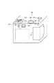
図1はデジタルカメラ101を背面から見たときの、操作部と表示部を示す図である。
【0020】
図1において、102はレリーズ動作を起動するレリーズボタン、103は光学ファインダー、104は撮影枚数等のカメラの状態を表示するLCD、105は電子ビューファインダーとカメラの状態を示す表示とを兼用するLCD、106はカメラのモードを選択するモードダイアルで、カメラの電源のオンとオフ、通常撮影モード、パノラマ撮影モード、画像再生表示モードを選択出来るモード選択手段である。
【0021】
107、108、109、110はモードの細部を設定する場合にLCDと連動して使用するボタンで、モードダイアル106でパノラマ撮影モードが選択された場合には、これらのボタンとLCD表示を使って、後に示すような2×2モード、横一列モード、縦一列モードを選択する。また、横一列モードが選択された場合には、さらに右から順番に撮影するか、あるいは左から撮影するかを選択を行う。また、縦一列モードが選択された場合には上から下の順番に撮影するか、あるいは下から上の順番に撮影するかの撮影方向の選択を行なう。
【0022】
各モードでの一組の画像の撮影を終了すると、107のSETボタンで終了する。111は記録媒体収納部の蓋。デジタルカメラ101は、カメラ全体の制御を内部のマイクロコンピュータで行なっており、以下のファイル制御も同様に制御される。
【0023】
図2はモードダイアル106でパノラマモードを選択したときに、ビューファインダー105に表示される画面である。
【0024】
図17は、本発明の実施形態の構成を示す図である。
【0025】
図17において、100は図1に示すデジタルカメラ101のブロック構成図である。
【0026】
10は撮影レンズ、12は絞り機能を備えるシャッター、14は光学像を電気信号に変換する撮像素子、16は撮像素子14のアナログ信号出力をディジタル信号に変換するA/D変換器である。
【0027】
18は撮像素子14、A/D変換器16、D/A変換器26にクロック信号や制御信号を供給するタイミング発生回路であり、メモリ制御回路22及びシステム制御回路50により制御される。
【0028】
20は画像処理回路であり、A/D変換器16からのデータ或いはメモリ制御回路22からのデータに対して所定の画素補完処理や色変換処理を行う。
【0029】
また、画像処理回路20においては、撮像した画像データを用いて所定の演算処理を行い、得られた演算結果に基づいてシステム制御回路50が露光制御手段40、測距制御手段42に対して制御を行う、TTL(スルー・ザ・レンズ)方式のAF(オートフォーカス)処理、AE(自動露出)処理、EF(フラッシュプリ発光)処理を行っている。
【0030】
さらに、画像処理回路20においては、撮像した画像データを用いて所定の演算処理を行い、得られた演算結果に基づいてTTL方式のAWB(オートホワイトバランス)処理も行っている。
【0031】
22はメモリ制御回路であり、A/D変換器16、タイミング発生回路18、画像処理回路20、画像表示メモリ24、D/A変換器26、メモリ30、圧縮・伸長回路32を制御する。
【0032】
A/D変換器16のデータが画像処理回路20、メモリ制御回路22を介して、或いはA/D変換器16のデータが直接メモリ制御回路22を介して、画像表示メモリ24或いはメモリ30に書き込まれる。
【0033】
24は画像表示メモリ、26はD/A変換器、28はTFT LCD等から成る画像表示部であり、画像表示メモリ24に書き込まれた表示用の画像データはD/A変換器26を介して画像表示部28により表示される。
【0034】
画像表示部28を用いて撮像した画像データを逐次表示すれば、電子ファインダー機能を実現することが可能である。
【0035】
また、画像表示部28は、システム制御回路50の指示により任意に表示をON/OFFすることが可能であり、表示をOFFにした場合には画像処理装置100の電力消費を大幅に低減することが出来る。
【0036】
30は撮影した静止画像や動画像を格納するためのメモリであり、所定枚数の静止画像や所定時間の動画像を格納するのに十分な記憶量を備えている。
【0037】
これにより、複数枚の静止画像を連続して撮影する連写撮影やパノラマ撮影の場合にも、高速かつ大量の画像書き込みをメモリ30に対して行うことが可能となる。
【0038】
また、メモリ30はシステム制御回路50の作業領域としても使用することが可能である。
【0039】
32は適応離散コサイン変換(ADCT)等により画像データを圧縮伸長する圧縮・伸長回路であり、メモリ30に格納された画像を読み込んで圧縮処理或いは伸長処理を行い、処理を終えたデータをメモリ30に書き込む。
【0040】
40は絞り機能を備えるシャッター12を制御する露光制御手段であり、フラッシュ48と連携することによりフラッシュ調光機能も有するものである。
【0041】
42は撮影レンズ10のフォーカシングを制御する測距制御手段、44は撮影レンズ10のズーミングを制御するズーム制御手段、46はバリアである保護手段9の動作を制御するバリア制御手段である。
【0042】
48はフラッシュであり、AF補助光の投光機能、フラッシュ調光機能も有する。
【0043】
露光制御手段40、測距制御手段42はTTL方式を用いて制御されており、撮像した画像データを画像処理回路20によって演算した演算結果に基づき、システム制御回路50が露光制御手段40、測距制御手段42に対して制御を行う。
【0044】
50は画像処理装置100全体を制御するシステム制御回路、52はシステム制御回路50の動作用の定数、変数、プログラム等を記憶するメモリである。
【0045】
54はシステム制御回路50でのプログラムの実行に応じて、文字、画像、音声等を用いて動作状態やメッセージ等を表示する液晶表示装置、スピーカー等の表示部であり、画像処理装置100の操作部近辺の視認し易い位置に単数或いは複数個所設置され、例えばLCDやLED、発音素子等の組み合わせにより構成されている。
【0046】
また、表示部54は、その一部の機能が光学ファインダー33内に設置されている。
【0047】
表示部54の表示内容のうち、LCD等に表示するものとしては、例えば、シングルショット/連写撮影表示、セルフタイマー表示、圧縮率表示、記録画素数表示、記録枚数表示、残撮影可能枚数表示、シャッタースピード表示、絞り値表示、露出補正表示、フラッシュ表示、赤目緩和表示、マクロ撮影表示、ブザー設定表示、時計用電池残量表示、電池残量表示、エラー表示、複数桁の数字による情報表示、記録媒体200及び210の着脱状態表示、通信I/F動作表示、日付け・時刻表示、外部コンピュータとの接続状態を示す表示、等がある。
【0048】
また、表示部54の表示内容のうち、光学ファインダー33内に表示するものとしては、例えば、合焦表示、撮影準備完了表示、手振れ警告表示、フラッシュ充電表示、フラッシュ充電完了表示、シャッタースピード表示、絞り値表示、露出補正表示、記録媒体書き込み動作表示、等がある。
【0049】
さらに、表示部54の表示内容のうち、LED等に表示するものとしては、例えば、合焦表示、撮影準備完了表示、手振れ警告表示、フラッシュ充電表示、フラッシュ充電完了表示、記録媒体書き込み動作表示、マクロ撮影設定通知表示、二次電池充電状態表示、等がある。
【0050】
そして、表示部54の表示内容のうち、ランプ等に表示するものとしては、例えば、セルフタイマー通知ランプ、等がある。このセルフタイマー通知ランプは、AF補助光と共用して用いても良い。
【0051】
56は電気的に消去・記録可能な不揮発性メモリであり、例えばEEPROM等が用いられる。
【0052】
60、62、64、66、68、70及び72は、システム制御回路50の各種の動作指示を入力するための操作手段であり、スイッチやダイアル、タッチパネル、視線検知によるポインティング、音声認識装置等の単数或いは複数の組み合わせで構成される。
【0053】
ここで、これらの操作手段の具体的な説明を行う。
【0054】
60はモードダイアルスイッチで、電源オフ、自動撮影モード、撮影モード、パノラマ撮影モード、再生モード、マルチ画面再生・消去モード、PC接続モード等の各機能モードを切り替え設定することが出来る。
【0055】
62はシャッタースイッチSW1で、不図示のシャッターボタンの操作途中でONとなり、AF(オートフォーカス)処理、AE(自動露出)処理、AWB(オートホワイトバランス)処理、EF(フラッシュプリ発光)処理等の動作開始を指示する。
【0056】
64はシャッタースイッチSW2で、不図示のシャッターボタンの操作完了でONとなり、撮像素子12から読み出した信号をA/D変換器16、メモリ制御回路22を介してメモリ30に画像データを書き込む露光処理、画像処理回路20やメモリ制御回路22での演算を用いた現像処理、メモリ30から画像データを読み出し、圧縮・伸長回路32で圧縮を行い、記録媒体200或いは210に画像データを書き込む記録処理という一連の処理の動作開始を指示する。
【0057】
66は画像表示ON/OFFスイッチで、画像表示部28のON/OFFを設定することが出来る。
【0058】
この機能により、光学ファインダー33を用いて撮影を行う際に、TFT LCD等から成る画像表示部への電流供給を遮断することにより、省電力を図ることが可能となる。
【0059】
68はクイックレビューON/OFFスイッチで、撮影直後に撮影した画像データを自動再生するクイックレビュー機能を設定する。なお、本実施例では特に、画像表示部28をOFFとした場合におけるクイックレビュー機能の設定をする機能を備えるものとする。
【0060】
70は各種ボタンやタッチパネル等からなる操作部で、メニューボタン、セットボタン、マクロボタン、マルチ画面再生改ページボタン、フラッシュ設定ボタン、単写/連写/セルフタイマー切り替えボタン、メニュー移動+(プラス)ボタン、メニュー移動−(マイナス)ボタン、再生画像移動+(プラス)ボタン、再生画像−(マイナス)ボタン、撮影画質選択ボタン、露出補正ボタン、日付/時間設定ボタン等がある。
【0061】
72は圧縮モードスイッチで、JPEG圧縮の圧縮率を選択するため、或いは撮像素子の信号をそのままディジタル化して記録媒体に記録するCCDRAWモードを選択するためのスイッチである。
【0062】
JPEG圧縮のモードは、例えばノーマルモードとファインモードが用意されている。
【0063】
JPEG圧縮のモードに於いては、撮像素子14から読み出されてA/D変換器16、画像処理回路20、メモリ制御回路22を介して、メモリ30に書き込まれた画像データを読み出し、圧縮・伸長回路32により設定した圧縮率に圧縮を行った後、記録媒体200或いは210に記録を行う。
【0064】
CCDRAWモードでは、撮像素子14の色フィルタの画素配列に応じて、ライン毎にそのまま画像データを読み出して、A/D変換器16、メモリ制御回路22を介して、メモリ30に書き込まれた画像データを読み出し、記録媒体200或いは210に記録を行う。
【0065】
80は電源制御手段で、電池検出回路、DC−DCコンバータ、通電するブロックを切り替えるスイッチ回路等により構成されており、電池の装着の有無、電池の種類、電池残量の検出を行い、検出結果及びシステム制御回路50の指示に基づいてDC−DCコンバータを制御し、必要な電圧を必要な期間、記録媒体を含む各部へ供給する。
【0066】
82はコネクタ、84はコネクタ、86はアルカリ電池やリチウム電池等の一次電池やNiCd電池やNiMH電池、Li電池等の二次電池、ACアダプター等からなる電源手段である。
【0067】
90及び94はメモリカードやハードディスク等の記録媒体とのインタフェース、92及び96はメモリカードやハードディスク等の記録媒体と接続を行うコネクタ、98はコネクタ92及び或いは96に記録媒体200或いは210が装着されているか否かを検知する記録媒体着脱検知手段である。
【0068】
なお、本実施形態では記録媒体を取り付けるインターフェース及びコネクタを2系統持つものとして説明している。もちろん、記録媒体を取り付けるインターフェース及びコネクタは、単数或いは複数、いずれの系統数を備える抗生としても構わない。また、異なる規格のインターフェース及びコネクタを組み合わせて備える構成としても構わない。インターフェース及びコネクタとしては、PCMCIAカードやCF(コンパクトフラッシュ)カード等の規格に準拠したものを用いて構成して構わない。
【0069】
さらに、インタフェース90及び94、そしてコネクタ92及び96をPCMCIAカードやCF(コンパクトフラッシュ)カード等の規格に準拠したものを用いて構成した場合、LANカードやモデムカード、USBカード、IEEE1394カード、P1284カード、SCSIカード、PHS等の通信カード、等の各種通信カードを接続することにより、他のコンピュータやプリンタ等の周辺機器との間で画像データや画像データに付属した管理情報を転送し合うことが出来る。
【0070】
102は、画像処理装置100のレンズ10を含む撮像部を覆う事により、撮像部の汚れや破損を防止するバリアである保護手段である。
【0071】
33は光学ファインダであり、画像表示部28による電子ファインダー機能を使用すること無しに、光学ファインダのみを用いて撮影を行うことが可能である。また、光学ファインダー33内には、表示部54の一部の機能、例えば、合焦表示、手振れ警告表示、フラッシュ充電表示、シャッタースピード表示、絞り値表示、露出補正表示などが設置されている。
【0072】
57は通信手段で、RS232CやUSB、IEEE1394、P1284、SCSI、モデム、LAN、無線通信、等の各種通信機能を有する。
【0073】
112は通信手段110により画像処理装置100を他の機器と接続するコネクタ或いは無線通信の場合はアンテナである。
【0074】
200はメモリカードやハードディスク等の記録媒体である。
【0075】
記録媒体200は、半導体メモリや磁気ディスク等から構成される記録部202、画像処理装置100とのインタフェース204、画像処理装置100と接続を行うコネクタ206を備えている。
【0076】
210はメモリカードやハードディスク等の記録媒体である。
【0077】
記録媒体210は、半導体メモリや磁気ディスク等から構成される記録部212、画像処理装置100とのインタフェース214、画像処理装置100と接続を行うコネクタ216を備えている。
【0078】
図2(A)は、パノラマモードの詳細を選択する画面で、モードダイアル106でパノラマモードを選択した直後、あるいは、2×2モード、横一列モード、縦一列モードのうち一つのモードでの撮影が終了したときに表示される。201、202、203は、夫々2×2モード、横一列モード、縦一列モードを示すアイコンで、110の〔+〕ボタンを押す毎に204の選択枠カーソルが移動する。好みのモードで、107の〔SET〕ボタンで選択指定する。
【0079】
図2(B)は、2×2モードで撮影している途中の画面で、右上の一枚を撮影後、右下の画像をこれから撮影するところである。右上205に撮影済みの画像が表示され、右下206には、これから撮影する画像がビューファインダーとして表示される。これから撮影する画像は、〔+〕ボタン110を押すことによって、4つの内から次々に選択でき、その場所がビューファインダーとして表示される。
【0080】
4枚の画像の撮影が終ったら、〔SET〕ボタン107を押して、4枚組の撮影が終了し、画像は図2(A)にもどる。〔SET〕ボタン107を押す前であれば、夫々の画像の撮り直しも出来る。撮り直しでは、画像ファイル名は、撮り直す前のファイル名のままで、画像データが、撮り直したものに入れ替わり保存される。
【0081】
図3は、第一の実施形態のファイル名を示す図である。
【0082】
DOSで扱えるように、ファイル名は、英数字8文字と、拡張子3文字とから構成される。ファイル名の頭の3文字は、単独撮影の場合は“IMG”,パノラマ撮影の場合は頭の2文字を後の画像の縫合せ(stitch)作業から“ST”、それに続く1文字はアルファベットの文字配列の頭から一文字ずつ抽出した文字“A”,“B”,“C”,…で構成する。このため、一組のファイル数の最大は26で、これを超えた構成が指示されても、受け付けない。
【0083】
ファイル名の次の5文字は、前記従来例に記載の特願平8−273494のファイル番号と同じように決められる。撮影する毎に1つずつ増していく5桁の数字によるファイル番号currFileNoが付せられる。ファイル番号currFileNoはカメラ内に保存されている。記録媒体が入れ替えられた時には、新しく装着された記録媒体に記録されているファイルのファイル名に付けられているファイル番号のうち最大のものFileNoFoundと、カメラ内に保存されているファイル番号とを比較して、 currFileNo >FileNoFound の場合はcurrFileNoをそのまま使い、そうでない場合は、 FileNoFound+1を新しくcurrFileNoとしてカメラに保存して使用する。ここでは、5桁数字の内、最上位の値が“0”の場合には、見やすいように“_”で置き換えている。拡張子の3文字は、JPEG圧縮された画像ファイルであるので、“.JPG”が付けられている。
【0084】
各ファイルは、検索のしやすいように、ファイル番号が50毎に別のディレクトリに整理される。ここでは、ファイル番号が3401から3450までのファイルは“CTG_0068.CTG”のディレクトリに、ファイル番号が3451から3500までのファイルは“CTG_0069.CTG”のディレクトリに整理されている。
【0085】
図4は、図3に対応したパノラマ画像の構成を示す図である。
【0086】
図4(A)は、2×2のパノラマモードの画像構成で、“STA_3435.JPG”から“STD_3438.JPG”までの4枚の画像ファイルに対応している。図4(B)は、横一列のパノラマモードの画像構成で、“STA_3441.JPG”と“STD_3442.JPG”の2枚の画像が、左から順番に撮影された場合を示す。図4(C)は、引き続き横一列のパノラマモードの画像構成であるが、撮影時には、4(B)の撮影が終了し、206のセットボタンを押して組の撮影の終了を指示した後に、モードダイアルは以前のパノラマモードのままで、2×2モード、横一列モード、縦一列モードから横一列モードを選択して、さらに撮影方向を選択した後に撮影される。
【0087】
“STA_3443.JPG”から“STD_3445.JPG”までの3枚が、ここでは、右から順番に撮影された場合を示している。図4(D)は、縦一列のパノラマモードの画像構成で、“STA_3450.JPG”と“STD_3451.JPG”の2枚の画像が、上から下に順番に撮影されたもので、ファイル番号が50毎にディレクトリを変えるという規則に従って、上下の二枚が夫々別のディレクトリに整理されている。
【0088】
位置に関する情報は、ここではファイル名には反映されていなくて、ファイル内に記録されている。
【0089】
図5は、第一の実施形態のファイル名を付与するときのフローチャート図である。撮影の前には、モードダイアルと細部設定ボタンで撮影モードと細部の設定が指示される。パノラマモードで、2×2モード、横一列モード、縦一列モードのいずれかが選択される度に、パノラマの組内で付ける番号STNoに“1”をセットする。また、ファイル番号currFileNoは、カメラ出荷時に“1”にセットされている。レリーズボタン102で撮影の後、画像処理を行い、保存データが確定した後、このフローに従ってファイル名を定めて画像データを記録媒体に保存する。
【0090】
上述の一連の処理を、以下、フローチャートに従って説明する。
【0091】
ステップS51では、現在のモードがパノラマモードに設定されているか否かが判断される。ステップS51で、パノラマモードが設定されていると判断された場合には、ステップS52でパノラマモードのファイル名を付与する。左から2文字は“ST”、左から3文字目には、アルファベットの文字を一文字ずつ“A”、“B”、“C”…と順番に要素に持つ配列AB〔〕から、AB〔STNo〕を抽出して、与える。次の5文字は、currFileNoの5桁の数字で、見やすいように、5桁目が“0”の場合は“_”に置き換える。拡張子は“.JPG”をつける。
【0092】
次に、ステップS53では、組内番号STNoを、1を加えた値に変更する。次に、ステップS54では、ファイル番号currFileNoを、1を加えた値に変更する。
【0093】
また、ステップS51でパノラマモードでなく、通常撮影モードが設定されていると判断された場合、ステップS55で通常撮影モードのファイル名を与える。左から3文字は“IMG”、次の5文字は、currFileNoの5桁の数字で、見やすいように、5桁目が“0”の場合は“_”に置き換える。拡張子は“.JPG”。次にステップS54に進む。
【0094】
ここでは、一枚の撮影毎にこのフローの処理が行われるので、ファイル名のアルファベットの順番とファイル番号の順番は、撮影の順番であり、また、データを保存する順番となる。
【0095】
ファイル名の頭が“STA”であると画像の組の頭のファイルであり、以後ファイル番号順に、次のファイル名の頭が“STA”または“IMG”となる手前までが一組の画像であることがファイル名から判断できる。
【0096】
以上説明したように、本実施形態によれば、複数のデータが一組となっているような場合に、組を構成することを示す文字、他の組とは区別する文字、ファイル番号を示す文字をファイル名に含ませることによって、ファイル名だけから、組に属するか否か、データ生成、保存の順番等が判断でき、使用者がデータの整理をする場合や、パーソナルコンピュータ上のプログラムで整理、処理する時に迅速に対応出来る。
【0097】
(第2の実施形態)
第2の実施形態を図6から図8に示す。
【0098】
第1の実施形態と同様の部分は説明を省く。
【0099】
図6はファイル名を示す図である。ファイル名の頭の3文字は、単独撮影の場合は“IMG”、パノラマ撮影の場合は頭の2文字を“PN”、それに続く1文字は、撮影の順番に、組が現れる毎に“A”,“B”,“C”,“D”,と続き“Z”までくると再び“A”からくりかえす文字で構成する。次の5文字はファイル番号である。
【0100】
図7は、図6に対応したパノラマ画像の構成を示す。
【0101】
図8は第2の実施形態のファイル名を付与するときのフローチャート図である。
【0102】
ファイル番号currFileNoは、カメラ出荷時に“1”にセットされており、また同時に、パノラマ番号PNNoが“1”にセットされる。撮影の前には、モードダイアルと細部設定ボタンで撮影モードと細部の設定が指示されている。
【0103】
パノラマモードで、2×2モード、横一列モード、縦一列モードのいずれかが選択される。レリーズボタン102で撮影の後、画像処理を行い、保存データが確定した後、このフローに従ってファイル名を定めて画像データを記録媒体に保存する。
【0104】
以下、フローチャートに従って説明する。
【0105】
ステップS81で、現在のモードがパノラマモードに設定されているか否かが判断される。ステップS81でパノラマモードが設定されていると判断された場合には、ステップS82でパノラマモードのファイル名を付与する。左から2文字は“PN”、左から3文字目には、アルファベットの文字を一文字ずつ“A”、“B”、“C”…と順番に要素に持つ配列AB〔〕から、AB〔PNNo〕を抽出して、与える。次の5文字は、currFileNoの5桁の数字である。
【0106】
次に、ステップS83では、ファイル番号currFileNoを、1を加えた値に変更する。
【0107】
また、ステップS81でパノラマモードでなく、通常撮影モードが設定されていると判断された場合、第1の実施形態と同様に、ステップS84で通常撮影モードのファイル名を与える。そしてステップS83に進む。パノラマ画像の一組の撮影が終了したときには、206のセットボタンが押され、組の撮影の終了が指示される。このときに、パノラマ番号PNNoを、1を加えた値に変更する(図示せず)。
【0108】
ファイル名の頭が“PN”であると画像の組に含まれるファイルであり、以後ファイル番号順に、ファイル名の3文字目が同じ文字のファイルが一組の画像であることがファイル名から判断できる。
【0109】
(第3の実施形態)
第3の実施例を図9から図11に示す。
【0110】
第1の実施形態と同様の部分は説明を省く。
【0111】
図9はファイル名を示す図である。ファイル名の頭の3文字は、単独撮影の場合は“IMG”,パノラマ撮影の場合は頭の1文字を撮影の順番に組が現れる毎に“P”,“Q”,“P”,“Q”,と繰り返す組分文字で、次の2文字は、パノラマ画像を構成する位置を示す。列と行を表す数字で、左上を“0”列“0”行として表している。次の5文字はファイル番号である。
【0112】
図10は、図9に対応したパノラマ画像の構成を示す。
【0113】
図11は第3の実施形態のファイル名を付与するときのフローチャート図である。ファイル番号currFileNoは、カメラ出荷時に“1”にセットされており、同時に組分文字が“P”にセットされている。撮影の前には、モードダイアルと細部設定ボタンで撮影モードと細部の設定が指示されている。パノラマモードで、2×2モード、横一列モード、縦一列モードのいずれかが選択され、撮影時には、ユーサーインターフェースの処理プログラムによって、これから撮影する画像が、パノラマのどの位置を構成するかの情報がファインダー103内あるいは電子ビューファインダー105に表示される。レリーズボタン102で撮影の後、画像処理を行い、保存データが確定した後、このフローに従ってファイル名を定めて画像データを記録媒体に保存する。
【0114】
以下、フローチャートに従って説明する。
【0115】
ステップS111では、現在のモードがパノラマモードであるか否かが判断される。ステップS111でパノラマモードが設定されていると判断された場合には、ステップS112では、パノラマ画像の構成位置の情報をユーサーインターフェースの処理のメモリから取得する。
【0116】
次に、ステップS113でファイル名を付与する。左端の文字を組分文字、左から二番目の文字は、パノラマ画像の何列目かを示す数字、左から三番目の文字は、パノラマ画像の何行めかを示す数字で、パノラマの左上端の画像を0列0行としている。次の5文字はファイル番号である。ステップS114、S115、S116で、組分文字が“P”,“Q”交互に現れるように設定し、ステップS117でファイル番号currFileNoを、1を加えた値に変更する。
【0117】
また、ステップS111で通常撮影モードであると判断された場合には、ステップS118で第1の実施形態と同じ処理をする。
【0118】
ファイル名の頭が“P”または“Q”のファイルが組に含まれる画像ファイルであり、ファイル番号順に並べて、“P”が並んでいるものが一組のパノラマ画像、または“Q”が並んでいるものが一組のパノラマ画像と判断出来る。
【0119】
また、一組の画像から、ファイル名の2文字目、3文字目からパノラマ画像を構成する位置が解る。
【0120】
(第4の実施形態)
第4の実施形態を図12から図14に示す。
【0121】
第1の実施例と同様の部分は説明を省く。
【0122】
図12はファイル名を示す図である。ファイル名の頭の3文字は、単独撮影の場合は“IMA”,パノラマ撮影の場合も、一枚目の画像は“IMA”で、二枚目以降は、順番に“IMB”,“IMC”,“IMD”,…とする。26枚を超える画像は受け付けない。次の5文字はファイル番号である。
【0123】
図13は、図12に対応したパノラマ画像の構成を示す。
【0124】
図14は第4の実施形態のファイル名を付与するときのフローチャート図である。ファイル番号currFileNoは、カメラ出荷時に“1”にセットされている。撮影の前には、モードダイアルと細部設定ボタンで撮影モードと細部の設定が指示されている。パノラマモードで、2×2モード、横一列モード、縦一列モードのいずれかが選択される時に、GRNoを“1”にセットする(図示せず)。レリーズボタン102で撮影の後、画像処理を行い、保存データが確定した後、このフローに従ってファイル名を定めて画像データを記録媒体に保存する。
【0125】
以下、フローチャートに従って説明する。
【0126】
ステップS141で、現在の撮影モードがパノラマモードであるか否かが判断される。ステップS141でパノラマモードであると判断された場合には、ステップS142では、その時に設定されているGRNoに従って、ファイル名を定める。ファイル名の頭の2文字は、“IM”、次の文字は、アルファベットの文字を一文字ずつ“A”、“B”、“C”…と順番に要素に持つ配列AB〔〕から、AB〔GRNo〕を抽出して与える。次の5文字はファイル番号である。
【0127】
次に、ステップS143でGRNoを、1を加えた値に変更し、ステップS144でファイル番号currFileNoを、1を加えた値に変更する。
【0128】
また、ステップS141で通常撮影モードであると判断された場合には、ステップS145でGRNoを“1”としてファイル名を定める。
【0129】
ファイル名の頭が“IMA”のファイル名だけでは、組に含まれるか否かは判断できないが、ファイル番号順にならべると、以後に“IMB”が続くか否かで、パノラマ画像の一部を構成するかどうか判断できる。
【0130】
以上の実施形態では、パノラマ撮影を例に挙げて説明したが、複数の画像を組として扱う場合には同様なファイル名の設定が出来る。
【0131】
例えば、連続写真でも同様なファイル名を付けることができる。また、上記実施形態では、一枚の画像の撮影毎にファイル名を付与して記録媒体に保存したために、ファイル番号の順番が撮影の順番であり、かつ保存の順番となったが、複数の画像を一度バッファメモリに保存しておいて、その後、記録媒体に保存する時に、記録位置の順番にファイル番号や組内の順番の文字を取得することもできる。
【0132】
また、上記実施形態では、組内の順番の文字や、組毎の順番の文字をアルファベットで示したが、桁数を上げて文字列としたり、数字や数字と英字との組合わせ、更には2バイトコードの文字でファイル名を表記することもできる。
【0133】
上記実施形態においては、プログラムをROMに保持する場合について説明したが、これに限定されるものではなく、任意の記憶媒体を用いて実現してもよい。また、同様の動作をする回路で実現してもよい。
【0134】
なお、本発明は、複数の機器から構成されるシステムに適用しても、1つの機器からなる装置に適用してもよい。前述した実施形態の機能を実現するソフトウエアのプログラムコードを記録した記録媒体を、システム或いは装置に供給し、そのシステム或いは装置のコンピュータ(またはCPUやMPU)が記録媒体に格納されたプログラムコードを読み出し実行することによっても、達成されることは言うまでもない。この場合、記録媒体から読み出されたプログラムコード自体が前述した実施形態の機能を実現することになり、そのプログラムコードを記録した記録媒体は本発明を構成することになる。
【0135】
プログラムコードを供給するための記録媒体としては、例えば、フロッピーディスク、ハードディスク、光ディスク、光磁気ディスク、CDーROM、CDーR、磁気テープ、不揮発性のメモリカード、ROMなどを用いることができる。
【0136】
また、コンピュータが読み出したプログラムコードを実行することにより、前述した実施形態の機能が実現されるだけでなく、そのプログラムコードの指示に基づき、コンピュータ上で稼働しているOSなどが実際の処理の一部または全部を行ない、その処理によって前述した実施形態の機能が実現される場合も含まれることは言うまでもない。
【0137】
更に、記録媒体から読み出されたプログラムコードが、コンピュータに挿入された機能拡張ボードやコンピュータに接続された機能拡張ユニットに備わるメモリに書き込まれた後、そのプログラムコードの指示に基づき、その機能拡張ボードや機能拡張ユニットに備わるCPUなどが実際の処理の一部または全部を行ない、その処理によって前述した実施形態の機能が実現される場合も含まれることは言うまでもない。
【0138】
【発明の効果】
以上説明したように、本発明によれば、複数の画像からなる一組の画像に対して、組を構成することを表す情報と撮影する毎に1つずつ増加する一連の番号と画像ファイルの種類を表す拡張子からなる画像ファイル名と組を構成する画像の位置情報とを付与するため、使用者は画像を整理する場合に迅速に対応することができる。
【図面の簡単な説明】
【図1】デジタルカメラの操作部と表示部を示す図である。
【図2】デジタルカメラのLCD表示の例を示す図である。
【図3】第1の実施形態のファイル名を示す図である。
【図4】第1の実施形態のパノラマ画像の構成を示す図である。
【図5】第1の実施形態のファイル名生成のフローチャート図である。
【図6】第2の実施形態のファイル名を示す図である。
【図7】第2の実施形態のパノラマ画像の構成を示す図である。
【図8】第2の実施形態のファイル名生成のフローチャート図である。
【図9】第3の実施形態のファイル名を示す図である。
【図10】第3の実施形態のパノラマ画像の構成を示す図である。
【図11】第3の実施形態のファイル名生成のフローチャート図である。
【図12】第4の実施形態のファイル名を示す図である。
【図13】第4の実施形態のパノラマ画像の構成を示す図である。
【図14】第4の実施形態のファイル名生成のフローチャート図である。
【図15】従来例のファイル名を示す図である。
【図16】従来例のパノラマ画像の構成を示す図である。
【図17】本発明の実施形態の構成を示す図である。
【符号の説明】
101 デジタルカメラ本体
102 レリーズボタン
103 光学ファインダー
104 サブLCD
105 電子ビューファインダーLCD
106 モードダイアル
107 細部設定ボタン
108 細部設定ボタン
109 細部設定ボタン
110 細部設定ボタン
111 記録媒体収納部蓋
201 2×2モード選択アイコン
202 横一列モード選択アイコン
203 縦一列モード選択アイコン
204 選択カーソル
205 撮影済画像表示画面
206 電子ビューファインダー表示画面[0001]
BACKGROUND OF THE INVENTION
The present invention relates to an image processing apparatus and method, an image file format, and a storage medium for recording a captured image as a digital image and reproducing the recorded digital image.
[0002]
[Prior art]
In recent years, digital electronic still cameras have been developed that convert image signals into digital signals and record them on a PCMCIA recording medium such as a semiconductor memory card or a small hard disk. The digital recording medium is configured such that data can be read by a personal computer.
[0003]
As a conventional technique of image data generated by such a digital electronic still camera, there is a format described in “Digital still camera IC memory card line DSC 68-pin standard” issued by JEIDA (Japan Electronics Industry Promotion Association). .
[0004]
In this standard, the PCMCIA recording medium is used as an MS-DOS compatible block device, and image files and audio files are recorded as files on the medium. Also, incidental information related to the image, such as the shooting date, shooting mode, shooting conditions, etc., is recorded in each file.
[0005]
When trying to play back image information and audio files recorded on this medium on a personal computer, the information on the files existing in a specific subdirectory is listed and displayed on the computer screen using the DOS function. In this way, the user can select a file to be played.
[0006]
However, in this case, information that can be understood by DOS is limited to the file name, file creation date, file size, and the like. That is, since these pieces of information are recorded in a continuous area on the medium in accordance with the DOS directory configuration rules, they can be restored relatively quickly. By making the file creation date coincide with the shooting date, it becomes possible to present information that is easier for the user to understand.
[0007]
In such file management, as a method for recording a plurality of images taken by continuous shooting so that they can be identified as a set, JP-A-5-252474 and JP-A-6-233225 disclose shooting by continuous shooting. It is disclosed that an image is recorded by including in a file name a character indicating this, a number assigned to each set of continuous shooting, and a continuous number at the time of continuous shooting.
[0008]
In addition, as a file management system for image data, the applicant of the present application, in Japanese Patent Application No. 8-273494, is a system in which file numbers are sequentially assigned to file names without overlapping as long as the same photographing apparatus is used. Has proposed.
[0009]
FIG. 15 shows an example of a file name according to this file management system. The first three characters of the file name are “IMG”, and the next five characters are given a file number currFileNo, which is a five-digit number that is incremented by one each time a picture is taken. This file number currFileNo is stored in the camera.
[0010]
When the recording medium is replaced, the largest file number attached to the file name of the file recorded on the newly installed recording medium is compared with the file number stored in the camera. If currFileNo> FileNoFound, currFileNo is used as it is. Otherwise, FileNoFound + 1 is newly stored in the camera as currFileNo and used.
[0011]
Here, when the highest value among the five-digit numbers is “0”, it is replaced with “_” for easy viewing. Since the three characters of the extension are JPEG-compressed image files, “.JPG” is added. Each file is organized in a separate directory for every 50 file numbers so that it can be easily searched. Here, files with
[0012]
FIG. 15 shows an image configuration when shooting in the panorama mode. The image not shown in FIG. 15 is single shooting, but it cannot be determined from the file name whether the panorama mode is set. Information about the positions that make up the panorama is recorded in the file.
[0013]
[Problems to be solved by the invention]
As described above, in the conventional technology, the file name system is different between the continuous shooting group and the single shooting, or the file name cannot be identified. There arises a problem that it is impossible to distinguish the shooting order of single shooting.
[0014]
In view of the above-described problems, an object of the present invention is to enable a user to display information related to an image recorded on a recording medium at high speed.
[0015]
[Means for Solving the Problems]
In order to solve the above-described problems, the present invention provides a set of images composed of a plurality of images, information indicating that the set is configured, and a series of numbers and image files that are incremented by one each time a photograph is taken. An assigning unit for assigning an image file name including an extension representing a type; and a storage unit for storing the image file name assigned by the assigning unit;, The assigning means assigns position information of images constituting the set.An image processing apparatus is provided.
[0016]
In order to solve the above-described problems, the present invention provides a set of images composed of a plurality of images, information indicating that the set is configured, and a series of numbers and image files that are incremented by one each time a photograph is taken. An image processing method comprising: assigning an image file name including an extension indicating a type; and storing the assigned image file name in a memoryAn image processing method characterized by adding position information of images constituting a setI will provide a.
[0017]
In order to solve the above-mentioned problems, the present invention provides a computer with a set of images composed of a plurality of images, information indicating that the set is configured, and a series of numbers and images that are incremented by one each time a photograph is taken. A computer-readable storage medium recording a program for executing an assigning procedure for assigning an image file name composed of an extension representing a file type and a control procedure for storing the assigned image file name in a memory. , Said grantprocedureProvides a computer-readable recording medium characterized by providing position information of images constituting a set.
[0019]
DETAILED DESCRIPTION OF THE INVENTION
(First embodiment)
FIG. 1 is a diagram illustrating an operation unit and a display unit when the
[0020]
In FIG. 1, 102 is a release button for starting a release operation, 103 is an optical viewfinder, 104 is an LCD that displays the camera status such as the number of shots, and 105 is an LCD that is both an electronic viewfinder and a display that indicates the camera status. , 106 is a mode dial for selecting a camera mode, which is a mode selection means for selecting the power on / off of the camera, the normal shooting mode, the panorama shooting mode, and the image reproduction display mode.
[0021]
[0022]
When the shooting of a set of images in each mode is completed, the process is terminated with the 107 SET button.
[0023]
FIG. 2 shows a screen displayed on the
[0024]
FIG. 17 is a diagram showing the configuration of the embodiment of the present invention.
[0025]
In FIG. 17,
[0026]
[0027]
A timing generation circuit 18 supplies a clock signal and a control signal to the
[0028]
[0029]
Further, the
[0030]
Further, the
[0031]
A
[0032]
The data of the A /
[0033]
[0034]
If the image data captured using the
[0035]
The
[0036]
Reference numeral 30 denotes a memory for storing captured still images and moving images, and has a sufficient storage capacity to store a predetermined number of still images and a predetermined time of moving images.
[0037]
This makes it possible to write a large amount of images to the memory 30 at high speed even in continuous shooting or panoramic shooting in which a plurality of still images are continuously shot.
[0038]
The memory 30 can also be used as a work area for the system control circuit 50.
[0039]
[0040]
[0041]
[0042]
A
[0043]
The exposure control means 40 and the distance measurement control means 42 are controlled using the TTL method. Based on the calculation result obtained by calculating the captured image data by the
[0044]
A system control circuit 50 controls the entire
[0045]
[0046]
The
[0047]
Among the display contents of the
[0048]
Further, among the display contents of the
[0049]
Further, among the display contents of the
[0050]
And what is displayed on a lamp etc. among the display contents of the
[0051]
[0052]
[0053]
Here, a specific description of these operating means will be given.
[0054]
Reference numeral 60 denotes a mode dial switch, which can switch and set various function modes such as power-off, automatic shooting mode, shooting mode, panoramic shooting mode, playback mode, multi-screen playback / erase mode, and PC connection mode.
[0055]
[0056]
[0057]
Reference numeral 66 denotes an image display ON / OFF switch that can set ON / OFF of the
[0058]
With this function, when photographing is performed using the
[0059]
Reference numeral 68 denotes a quick review ON / OFF switch, which sets a quick review function for automatically reproducing image data taken immediately after photographing. In this embodiment, it is assumed that a function for setting the quick review function when the
[0060]
[0061]
Reference numeral 72 denotes a compression mode switch, which is a switch for selecting a compression rate for JPEG compression, or for selecting a CCD RAW mode in which a signal from an image sensor is directly digitized and recorded on a recording medium.
[0062]
For example, a normal mode and a fine mode are prepared as JPEG compression modes.
[0063]
In the JPEG compression mode, image data read from the
[0064]
In the CCD RAW mode, the image data is read as it is for each line in accordance with the pixel arrangement of the color filter of the
[0065]
Reference numeral 80 denotes a power supply control means, which includes a battery detection circuit, a DC-DC converter, a switch circuit for switching a block to be energized, etc., and detects the presence / absence of a battery, the type of battery, the remaining battery level, In addition, the DC-DC converter is controlled based on an instruction from the system control circuit 50, and a necessary voltage is supplied to each unit including the recording medium for a necessary period.
[0066]
[0067]
90 and 94 are interfaces with a recording medium such as a memory card or a hard disk, 92 and 96 are connectors for connecting to a recording medium such as a memory card or a hard disk, and 98 is a
[0068]
In the present embodiment, it is assumed that there are two systems of interfaces and connectors for attaching a recording medium. Of course, the interface and connector to which the recording medium is attached may be one or a plurality of antibiotics having any number of lines. Moreover, it is good also as a structure provided with combining the interface and connector of a different standard. The interface and connector may be configured using a PCMCIA card, a CF (compact flash) card, or the like that conforms to a standard.
[0069]
Further, when the
[0070]
[0071]
[0072]
A communication means 57 has various communication functions such as RS232C, USB, IEEE1394, P1284, SCSI, modem, LAN, and wireless communication.
[0073]
[0074]
[0075]
The
[0076]
Reference numeral 210 denotes a recording medium such as a memory card or a hard disk.
[0077]
The recording medium 210 includes a
[0078]
FIG. 2A is a screen for selecting the details of the panorama mode. Immediately after selecting the panorama mode with the
[0079]
FIG. 2B is a screen in the middle of shooting in the 2 × 2 mode, where the upper right image is shot and then the lower right image is shot. A captured image is displayed in the
[0080]
When the four images have been photographed, the [SET]
[0081]
FIG. 3 is a diagram illustrating file names according to the first embodiment.
[0082]
The file name is composed of 8 alphanumeric characters and an extension of 3 characters so that it can be handled by DOS. The first three characters of the file name are “IMG” for single shooting, “ST” for the panoramic shooting, and the first two characters are alphabetical characters after the stitching of the subsequent image. Consists of characters “A”, “B”, “C”,... Extracted one by one from the beginning of the character array. Therefore, the maximum number of files in a set is 26, and even if a configuration exceeding this is instructed, it is not accepted.
[0083]
The next five characters of the file name are determined in the same manner as the file number of Japanese Patent Application No. 8-273494 described in the prior art. A file number, currFileNo, is added with a 5-digit number that is incremented by 1 each time a picture is taken. The file number currFileNo is stored in the camera. When the recording medium is replaced, the largest file number attached to the file name of the file recorded on the newly installed recording medium is compared with the file number stored in the camera. If currFileNo> FileNoFound, currFileNo is used as it is. Otherwise, FileNoFound + 1 is newly stored in the camera as currFileNo and used. Here, when the highest value among the five-digit numbers is “0”, it is replaced with “_” for easy viewing. Since the three characters of the extension are JPEG-compressed image files, “.JPG” is added.
[0084]
Each file is organized in a separate directory for every 50 file numbers so that it can be easily searched. Here, files with file numbers 3401 to 3450 are arranged in a directory “CTG_0068.CTG”, and files with file numbers 3451 to 3500 are arranged in a directory “CTG_0069.CTG”.
[0085]
FIG. 4 is a diagram illustrating a configuration of a panoramic image corresponding to FIG.
[0086]
FIG. 4A shows a 2 × 2 panoramic mode image configuration, which corresponds to four image files from “STA_3435.JPG” to “STD_3438.JPG”. FIG. 4B shows a case where two images of “STA_3441.JPG” and “STD_3442.JPG” are taken in order from the left in an image configuration in a horizontal row of panoramic modes. FIG. 4C shows the image configuration in the panoramic mode in a horizontal row. At the time of shooting, the shooting of 4 (B) is finished, and after pressing the
[0087]
Here, three images from “STA_3443.JPG” to “STD_3445.JPG” are taken in order from the right. Fig. 4 (D) shows an image configuration in a single vertical panorama mode. Two images of "STA_3450.JPG" and "STD_3451.JPG" were taken in order from top to bottom. According to the rule of changing the directory every 50, the upper and lower two are arranged in different directories.
[0088]
Here, the information regarding the position is not reflected in the file name, but is recorded in the file.
[0089]
FIG. 5 is a flowchart for assigning a file name according to the first embodiment. Before shooting, the mode dial and detail setting button are used to instruct the shooting mode and detail settings. Each time the panorama mode is selected from the 2 × 2 mode, the horizontal one-line mode, and the vertical one-line mode, “1” is set to the number STNo assigned in the panorama group. The file number currFileNo is set to “1” when the camera is shipped. After shooting with the
[0090]
The above-described series of processing will be described below according to the flowchart.
[0091]
In step S51, it is determined whether or not the current mode is set to the panorama mode. If it is determined in step S51 that the panorama mode is set, a panorama mode file name is assigned in step S52. The second character from the left is “ST”, and the third character from the left is the alphabet “A”, “B”, “C”, and so on. ] Is extracted and given. The next five characters are the five-digit number of currFileNo. To make it easier to see, if the fifth digit is “0”, replace it with “_”. The extension is “.JPG”.
[0092]
Next, in step S53, the group number STNo is changed to a value obtained by adding 1. Next, in step S54, the file number currFileNo is changed to a value obtained by adding 1.
[0093]
If it is determined in step S51 that the normal shooting mode is set instead of the panorama mode, the file name of the normal shooting mode is given in step S55. The three characters from the left are “IMG”, and the next five characters are the five-digit number of currFileNo. To make it easier to see, if the fifth digit is “0”, replace it with “_”. The extension is “.JPG”. Next, the process proceeds to step S54.
[0094]
Here, since the processing of this flow is performed for each shooting, the alphabetical order of the file names and the order of the file numbers are the shooting order and the order in which the data is stored.
[0095]
If the file name starts with “STA”, it is the first file in the image set. After that, the next file name starts with “STA” or “IMG” before the next file name. It can be determined from the file name.
[0096]
As described above, according to the present embodiment, when a plurality of pieces of data are in one set, a character indicating that the set is configured, a character that is distinguished from other sets, and a file number are indicated. By including characters in the file name, it is possible to determine whether it belongs to a set, the order of data generation, storage, etc. from the file name alone. The user can organize the data or use a program on a personal computer. It can respond quickly when organizing and processing.
[0097]
(Second Embodiment)
A second embodiment is shown in FIGS.
[0098]
Description of the same parts as those in the first embodiment will be omitted.
[0099]
FIG. 6 shows file names. The first three characters of the file name are “IMG” for single shooting, “PN” for the first two characters for panoramic shooting, and the next one is “A” every time a pair appears in the shooting order. “,” “B,” “C,” “D,” and so on up to “Z”. The next five characters are the file number.
[0100]
FIG. 7 shows the configuration of a panoramic image corresponding to FIG.
[0101]
FIG. 8 is a flowchart for assigning a file name according to the second embodiment.
[0102]
The file number currFileNo is set to “1” at the time of camera shipment, and at the same time, the panorama number PNNo is set to “1”. Before shooting, the mode dial and detail setting buttons are used to instruct the shooting mode and detail settings.
[0103]
In the panorama mode, any of 2 × 2 mode, horizontal single-row mode, and vertical single-row mode is selected. After shooting with the
[0104]
Hereinafter, it demonstrates according to a flowchart.
[0105]
In step S81, it is determined whether or not the current mode is set to the panorama mode. If it is determined in step S81 that the panorama mode is set, a panorama mode file name is assigned in step S82. The second character from the left is “PN”, and the third character from the left is the alphabet “A”, “B”, “C”, and so on. ] Is extracted and given. The next five characters are the five-digit number of currFileNo.
[0106]
In step S83, the file number currFileNo is changed to a value obtained by adding 1.
[0107]
If it is determined in step S81 that the normal shooting mode is set instead of the panorama mode, the file name of the normal shooting mode is given in step S84 as in the first embodiment. Then, the process proceeds to step S83. When the shooting of a set of panoramic images is completed, the
[0108]
If the file name starts with “PN”, it is a file included in the set of images, and from the file name, it is determined from the file name that the third character of the file name is the same character in the order of the file number. it can.
[0109]
(Third embodiment)
A third embodiment is shown in FIGS.
[0110]
Description of the same parts as those in the first embodiment will be omitted.
[0111]
FIG. 9 is a diagram showing file names. The first three letters of the file name are “IMG” for single shooting and “P”, “Q”, “P”, “ The next two characters indicate the position that forms the panoramic image. The numbers represent columns and rows, and the upper left is represented as “0” columns “0” rows. The next five characters are the file number.
[0112]
FIG. 10 shows the configuration of a panoramic image corresponding to FIG.
[0113]
FIG. 11 is a flowchart for assigning a file name according to the third embodiment. The file number currFileNo is set to “1” at the time of camera shipment, and at the same time, the character set is set to “P”. Before shooting, the mode dial and detail setting buttons are used to instruct the shooting mode and detail settings. In the panorama mode, any one of 2 × 2 mode, horizontal one-row mode, and vertical one-row mode is selected, and at the time of shooting, information on which position of the panorama is configured by an image to be shot by the user interface processing program. It is displayed in the
[0114]
Hereinafter, it demonstrates according to a flowchart.
[0115]
In step S111, it is determined whether or not the current mode is a panorama mode. If it is determined in step S111 that the panorama mode is set, in step S112, information on the configuration position of the panoramic image is acquired from the memory of the user interface process.
[0116]
In step S113, a file name is assigned. The leftmost character is a grouped character, the second character from the left is a number indicating the column number of the panorama image, the third character from the left is a number indicating the line number of the panorama image, and the upper left corner of the panorama image The image of 0 column 0 row. The next five characters are the file number. In steps S114, S115, and S116, the set characters are set to appear alternately as “P” and “Q”, and in step S117, the file number currFileNo is changed to a value obtained by adding 1.
[0117]
If it is determined in step S111 that the normal shooting mode is set, the same processing as in the first embodiment is performed in step S118.
[0118]
An image file whose file name begins with “P” or “Q” is included in the set, arranged in order of file number, and “P” is a set of panoramic images or “Q” Can be judged as a set of panoramic images.
[0119]
In addition, the position of the panoramic image can be determined from the second and third characters of the file name from a set of images.
[0120]
(Fourth embodiment)
A fourth embodiment is shown in FIGS.
[0121]
A description of the same parts as in the first embodiment will be omitted.
[0122]
FIG. 12 shows file names. The first three characters of the file name are “IMA” for single shooting, “IMA” for panoramic shooting, “IMA” for the first image, and “IMB”, “IMC” for the second and subsequent images. , “IMD”, and so on. Images with more than 26 images will not be accepted. The next five characters are the file number.
[0123]
FIG. 13 shows the configuration of a panoramic image corresponding to FIG.
[0124]
FIG. 14 is a flowchart for assigning a file name according to the fourth embodiment. The file number currFileNo is set to “1” at the time of camera shipment. Before shooting, the mode dial and detail setting buttons are used to instruct the shooting mode and detail settings. When any one of the 2 × 2 mode, the horizontal one-row mode, and the vertical one-row mode is selected in the panorama mode, GRNo is set to “1” (not shown). After shooting with the
[0125]
Hereinafter, it demonstrates according to a flowchart.
[0126]
In step S141, it is determined whether or not the current shooting mode is a panorama mode. If it is determined in step S141 that the panorama mode is selected, a file name is determined in step S142 according to the GRNo set at that time. The first two characters of the file name are “IM”, and the next character is an alphabetical character “A”, “B”, “C”, and so on. GRNo] is extracted and given. The next five characters are the file number.
[0127]
In step S143, GRNo is changed to a value obtained by adding 1, and in step S144, the file number currFileNo is changed to a value obtained by adding 1.
[0128]
If it is determined in step S141 that the camera is in the normal shooting mode, the file name is determined by setting GRNo to “1” in step S145.
[0129]
It is not possible to determine whether the file name begins with “IMA” alone or not, but if it is sorted in the order of file number, a part of the panoramic image is determined by whether or not “IMB” follows. Can determine whether to configure.
[0130]
In the above embodiment, panoramic shooting has been described as an example. However, when a plurality of images are handled as a set, a similar file name can be set.
[0131]
For example, the same file name can be assigned to continuous photos. Further, in the above embodiment, since a file name is assigned and saved in the recording medium every time one image is shot, the order of the file numbers is the order of shooting and the order of saving. When the image is once stored in the buffer memory and then stored in the recording medium, the file number and the characters in the order in the set can be acquired in the order of the recording position.
[0132]
Further, in the above embodiment, the characters in the order in the set and the characters in the order of each set are shown in alphabet, but the number of digits is increased to form a character string, a combination of numbers, numbers and letters, The file name can also be expressed by a 2-byte code character.
[0133]
In the above embodiment, the case where the program is stored in the ROM has been described. However, the present invention is not limited to this, and may be realized using an arbitrary storage medium. Further, it may be realized by a circuit that performs the same operation.
[0134]
The present invention may be applied to a system composed of a plurality of devices or an apparatus composed of a single device. A recording medium recording software program codes for realizing the functions of the above-described embodiments is supplied to a system or apparatus, and a computer (or CPU or MPU) of the system or apparatus stores program codes stored in the recording medium. Needless to say, this can also be achieved by executing read. In this case, the program code itself read from the recording medium realizes the functions of the above-described embodiment, and the recording medium on which the program code is recorded constitutes the present invention.
[0135]
As a recording medium for supplying the program code, for example, a floppy disk, a hard disk, an optical disk, a magneto-optical disk, a CD-ROM, a CD-R, a magnetic tape, a nonvolatile memory card, a ROM, or the like can be used.
[0136]
Further, by executing the program code read by the computer, not only the functions of the above-described embodiments are realized, but also an OS running on the computer performs actual processing based on an instruction of the program code. Needless to say, a case where the function of the above-described embodiment is realized by performing part or all of the processing, is also included.
[0137]
Further, after the program code read from the recording medium is written in a memory provided in a function expansion board inserted into the computer or a function expansion unit connected to the computer, the function expansion is performed based on the instruction of the program code. It goes without saying that the CPU or the like provided in the board or the function expansion unit performs part or all of the actual processing and the functions of the above-described embodiments are realized by the processing.
[0138]
【The invention's effect】
As described above, according to the present invention, for a set of images made up of a plurality of images, information indicating that the set is composed, and a series of numbers and image files that are incremented by one each time a picture is taken. Image file name consisting of the extension indicating the typeAnd the position information of the images that make up the pairTo giveThe user can respond quickly when organizing images.
[Brief description of the drawings]
FIG. 1 is a diagram illustrating an operation unit and a display unit of a digital camera.
FIG. 2 is a diagram illustrating an example of an LCD display of a digital camera.
FIG. 3 is a diagram illustrating file names according to the first embodiment.
FIG. 4 is a diagram illustrating a configuration of a panoramic image according to the first embodiment.
FIG. 5 is a flowchart of file name generation according to the first embodiment.
FIG. 6 is a diagram illustrating file names according to the second embodiment.
FIG. 7 is a diagram illustrating a configuration of a panoramic image according to a second embodiment.
FIG. 8 is a flowchart of file name generation according to the second embodiment.
FIG. 9 is a diagram illustrating file names according to the third embodiment.
FIG. 10 is a diagram illustrating a configuration of a panoramic image according to a third embodiment.
FIG. 11 is a flowchart of file name generation according to the third embodiment.
FIG. 12 is a diagram illustrating file names according to the fourth embodiment.
FIG. 13 is a diagram illustrating a configuration of a panoramic image according to a fourth embodiment.
FIG. 14 is a flowchart of file name generation according to the fourth embodiment.
FIG. 15 is a diagram illustrating a file name of a conventional example.
FIG. 16 is a diagram illustrating a configuration of a panoramic image of a conventional example.
FIG. 17 is a diagram showing a configuration of an exemplary embodiment of the present invention.
[Explanation of symbols]
101 Digital camera body
102 Release button
103 Optical viewfinder
104 Sub LCD
105 Electronic viewfinder LCD
106 mode dial
107 Detail setting button
108 Detail setting button
109 Detail setting button
110 Detail setting button
111 Recording medium storage cover
201 2 × 2 mode selection icon
202 Horizontal single row mode selection icon
203 Vertical single row mode selection icon
204 Selection cursor
205 Captured image display screen
206 Electronic viewfinder display screen
Claims (9)
前記付与手段により付与された画像ファイル名を記憶する記憶手段と、
前記付与手段は、組を構成する画像の位置情報を付与することを特徴とする画像処理装置。For a set of images consisting of a plurality of images, an image file name consisting of information indicating that the set is composed, a series of numbers that are incremented by one every time a photograph is taken, and an extension that indicates the type of the image file is assigned. Granting means to
Storage means for storing the image file name assigned by the assigning means;
The image processing apparatus according to claim 1, wherein the assigning unit assigns position information of images constituting the set.
前記モード設定手段により設定された入力モードに応じて前記付与手段を制御する制御手段と
を有する事を特徴とする請求項1に記載の画像処理装置。A mode setting means for setting an image input mode;
The image processing apparatus according to claim 1, further comprising: a control unit that controls the applying unit according to an input mode set by the mode setting unit.
前記付与された画像ファイル名をメモリに記憶させることを特徴とする画像処理方法であって、
組を構成する画像の位置情報を付与することを特徴とする画像処理方法。For a set of images consisting of a plurality of images, an image file name consisting of information indicating that the set is configured, a series of numbers that are incremented by one each time a photograph is taken, and an extension that indicates the type of the image file is assigned. And
An image processing method characterized by storing the assigned image file name in a memory,
An image processing method characterized by adding position information of images constituting a set.
前記設定された入力モードに応じて画像ファイル名の付与を制御することを特徴とする請求項5に記載の画像処理方法。Set the image input mode,
6. The image processing method according to claim 5, wherein the assignment of an image file name is controlled according to the set input mode.
前記付与手順は、組を構成する画像の位置情報を付与することを特徴とするコンピュータ読み取り可能な記録媒体。Image file name consisting of information representing the composition of a set of images consisting of a plurality of images on a computer, a series of numbers incremented by one each time a photograph is taken, and an extension representing the type of image file A computer-readable storage medium storing a program for executing a granting procedure for granting a control procedure for storing the given image file name in a memory,
A computer-readable recording medium characterized in that the assigning step assigns position information of images constituting a set.
Priority Applications (4)
| Application Number | Priority Date | Filing Date | Title |
|---|---|---|---|
| JP06123998A JP3862404B2 (en) | 1998-03-12 | 1998-03-12 | Image processing apparatus and method, image file format, and storage medium |
| US09/265,586 US6704465B2 (en) | 1998-03-12 | 1999-03-10 | Image processing apparatus and its processing method, storage medium, and image file format |
| DE69912663T DE69912663T2 (en) | 1998-03-12 | 1999-03-11 | Image processing device and method, storage medium, and image data group format |
| EP99301838A EP0942584B1 (en) | 1998-03-12 | 1999-03-11 | Image processing apparatus and its processing method, storage medium, and image file format |
Applications Claiming Priority (1)
| Application Number | Priority Date | Filing Date | Title |
|---|---|---|---|
| JP06123998A JP3862404B2 (en) | 1998-03-12 | 1998-03-12 | Image processing apparatus and method, image file format, and storage medium |
Publications (2)
| Publication Number | Publication Date |
|---|---|
| JPH11261937A JPH11261937A (en) | 1999-09-24 |
| JP3862404B2 true JP3862404B2 (en) | 2006-12-27 |
Family
ID=13165490
Family Applications (1)
| Application Number | Title | Priority Date | Filing Date |
|---|---|---|---|
| JP06123998A Expired - Fee Related JP3862404B2 (en) | 1998-03-12 | 1998-03-12 | Image processing apparatus and method, image file format, and storage medium |
Country Status (4)
| Country | Link |
|---|---|
| US (1) | US6704465B2 (en) |
| EP (1) | EP0942584B1 (en) |
| JP (1) | JP3862404B2 (en) |
| DE (1) | DE69912663T2 (en) |
Families Citing this family (34)
| Publication number | Priority date | Publication date | Assignee | Title |
|---|---|---|---|---|
| JP4809960B2 (en) | 1999-04-12 | 2011-11-09 | キヤノン株式会社 | Image processing apparatus, method, and recording medium |
| US6873367B1 (en) * | 1999-06-03 | 2005-03-29 | Olympus Optical Co., Ltd. | Electronic camera system |
| US7064783B2 (en) * | 1999-12-31 | 2006-06-20 | Stmicroelectronics, Inc. | Still picture format for subsequent picture stitching for forming a panoramic image |
| JP2001290683A (en) * | 2000-04-05 | 2001-10-19 | Nikon Corp | File-managing device and recording medium with file management program recorded thereon |
| US20020051065A1 (en) * | 2000-04-26 | 2002-05-02 | Nikon Corporation | Recording medium for data file management, apparatus for data file management, handling apparatus for image data, and image capturing system |
| JP2002135692A (en) * | 2000-10-27 | 2002-05-10 | Toshiba Corp | Electronic camera apparatus and file-managing method |
| JP4142846B2 (en) * | 2000-12-27 | 2008-09-03 | 株式会社東芝 | Electronic camera device and control method thereof |
| JP4434502B2 (en) * | 2001-01-19 | 2010-03-17 | 富士フイルム株式会社 | Digital camera |
| WO2002084999A1 (en) * | 2001-04-06 | 2002-10-24 | Sony Corporation | Digital camera and data transfer method |
| US20020176628A1 (en) | 2001-05-22 | 2002-11-28 | Starkweather Gary K. | Document imaging and indexing system |
| US6943842B2 (en) * | 2001-11-02 | 2005-09-13 | Hewlett-Packard Development Company, L.P. | Image browsing user interface apparatus and method |
| US7583293B2 (en) * | 2001-12-06 | 2009-09-01 | Aptina Imaging Corporation | Apparatus and method for generating multi-image scenes with a camera |
| US7084910B2 (en) * | 2002-02-08 | 2006-08-01 | Hewlett-Packard Development Company, L.P. | System and method for using multiple images in a digital image capture device |
| US7466336B2 (en) * | 2002-09-05 | 2008-12-16 | Eastman Kodak Company | Camera and method for composing multi-perspective images |
| JP4434624B2 (en) * | 2003-05-12 | 2010-03-17 | キヤノン株式会社 | Imaging apparatus, imaging method, computer program, and computer-readable storage medium |
| JP4177713B2 (en) | 2003-05-30 | 2008-11-05 | 京セラ株式会社 | Imaging device |
| US7855727B2 (en) * | 2004-09-15 | 2010-12-21 | Gyrus Acmi, Inc. | Endoscopy device supporting multiple input devices |
| FR2881598B1 (en) * | 2005-02-01 | 2007-08-03 | Canon Kk | METHOD AND DEVICE FOR RECORDING IMAGES COMPRISING PANORAMA, VISUALIZING AND MODIFYING PANORAMA |
| JP4743180B2 (en) * | 2006-09-28 | 2011-08-10 | セイコーエプソン株式会社 | Image display control device, photographing device, image display method and program thereof |
| JP4743179B2 (en) * | 2006-09-28 | 2011-08-10 | セイコーエプソン株式会社 | Image display control device, photographing device, image display method and program thereof |
| JP4569561B2 (en) * | 2006-12-01 | 2010-10-27 | 富士フイルム株式会社 | Image file creation device |
| KR101371414B1 (en) * | 2007-01-31 | 2014-03-10 | 삼성전자주식회사 | Combination A/V apparatus with multi function and method for providing UI |
| KR101396348B1 (en) * | 2007-03-08 | 2014-05-19 | 삼성전자주식회사 | Apparatus for processing digital image and method for managing file thereof |
| JP4650516B2 (en) * | 2008-04-09 | 2011-03-16 | ソニー株式会社 | Imaging data management method and imaging apparatus |
| JP2010103692A (en) * | 2008-10-22 | 2010-05-06 | Canon Inc | Image output apparatus, image output method, and control program |
| JP4893843B2 (en) * | 2010-04-12 | 2012-03-07 | 株式会社ニコン | Data file management device and computer-readable recording medium for data file management |
| JP5794657B2 (en) * | 2010-08-24 | 2015-10-14 | キヤノン株式会社 | Imaging control apparatus and imaging control method |
| US9734168B1 (en) * | 2013-12-08 | 2017-08-15 | Jennifer Shin | Method and system for organizing digital files |
| JP6265764B2 (en) * | 2014-01-31 | 2018-01-24 | キヤノン株式会社 | IMAGING DEVICE AND IMAGING DEVICE CONTROL METHOD |
| US10609270B2 (en) | 2014-11-18 | 2020-03-31 | The Invention Science Fund Ii, Llc | Devices, methods and systems for visual imaging arrays |
| US20190028721A1 (en) * | 2014-11-18 | 2019-01-24 | Elwha Llc | Imaging device system with edge processing |
| DE102015214281A1 (en) | 2015-07-28 | 2017-02-02 | Hectronic Gmbh | Method for activating a functional unit of a plurality of functional units of a tank installation |
| US11200205B2 (en) | 2020-01-31 | 2021-12-14 | EMC IP Holding Company LLC | Displaying an alert and options when deleting a file that is associated with a sequence of files |
| US11199948B2 (en) * | 2020-01-31 | 2021-12-14 | EMC IP Holding Company LLC | Displaying a sequence and files associated with the sequence having a missing file |
Family Cites Families (15)
| Publication number | Priority date | Publication date | Assignee | Title |
|---|---|---|---|---|
| US5130813A (en) * | 1988-08-31 | 1992-07-14 | Casio Computer Co., Ltd. | Image data supervising system |
| JP3250623B2 (en) | 1992-03-04 | 2002-01-28 | オリンパス光学工業株式会社 | camera |
| US5381526A (en) | 1992-09-11 | 1995-01-10 | Eastman Kodak Company | Method and apparatus for storing and retrieving generalized image data |
| JPH06233225A (en) | 1992-12-08 | 1994-08-19 | Nikon Corp | Image data recording method for digital still video camera |
| JPH06258723A (en) * | 1993-03-08 | 1994-09-16 | Olympus Optical Co Ltd | Panoramic photographic processing system |
| US5739850A (en) * | 1993-11-30 | 1998-04-14 | Canon Kabushiki Kaisha | Apparatus for improving the image and sound processing capabilities of a camera |
| JP3623983B2 (en) | 1994-04-28 | 2005-02-23 | キヤノン株式会社 | Image file recording / reproducing apparatus and method |
| US5724582A (en) * | 1994-05-27 | 1998-03-03 | Eastman Kodak Company | Medical image archiving with lossy images on two or more recordable CDs |
| JPH08273494A (en) | 1995-04-04 | 1996-10-18 | Energy Support Corp | Fixed electrode part structure in air switchgear |
| US5682197A (en) * | 1995-05-12 | 1997-10-28 | Eastman Kodak Company | Electronic panoramic camera for use with an external processor |
| US5799319A (en) * | 1995-07-13 | 1998-08-25 | Atkins; Hank | Method for naming computer files |
| JPH09270902A (en) * | 1996-01-31 | 1997-10-14 | Ricoh Co Ltd | Image filing method and device therefor |
| JPH09326917A (en) * | 1996-06-06 | 1997-12-16 | Fuji Photo Film Co Ltd | Image synthesis device and its method |
| US6346998B2 (en) * | 1996-11-20 | 2002-02-12 | Fuji Photo Film Co., Ltd. | Picture image outputting method and photograph finishing system using the method |
| US5779319A (en) | 1997-02-03 | 1998-07-14 | Indiana Mills And Manufacturing, Inc. | Child seat retractor |
-
1998
- 1998-03-12 JP JP06123998A patent/JP3862404B2/en not_active Expired - Fee Related
-
1999
- 1999-03-10 US US09/265,586 patent/US6704465B2/en not_active Expired - Lifetime
- 1999-03-11 DE DE69912663T patent/DE69912663T2/en not_active Expired - Lifetime
- 1999-03-11 EP EP99301838A patent/EP0942584B1/en not_active Expired - Lifetime
Also Published As
| Publication number | Publication date |
|---|---|
| EP0942584A2 (en) | 1999-09-15 |
| US20030169349A1 (en) | 2003-09-11 |
| US6704465B2 (en) | 2004-03-09 |
| DE69912663D1 (en) | 2003-12-18 |
| EP0942584B1 (en) | 2003-11-12 |
| JPH11261937A (en) | 1999-09-24 |
| DE69912663T2 (en) | 2004-08-19 |
| EP0942584A3 (en) | 2000-08-09 |
Similar Documents
| Publication | Publication Date | Title |
|---|---|---|
| JP3862404B2 (en) | Image processing apparatus and method, image file format, and storage medium | |
| JP4481842B2 (en) | Imaging apparatus and control method thereof | |
| US8373787B2 (en) | Image processing apparatus, image processing system, control method of the image processing apparatus, and recording medium having recorded thereon a computer program for executing the control program | |
| JP4541459B2 (en) | Digital camera | |
| US20120176512A1 (en) | Image storage apparatus, image storage method, and control program executed in image storage apparatus | |
| JP4533017B2 (en) | Imaging device | |
| KR100756155B1 (en) | Image processing apparatus, control method thereof and storage medium | |
| US7639299B2 (en) | Image pickup apparatus and control method therefor | |
| JP4612874B2 (en) | Imaging apparatus and control method thereof | |
| JP4498169B2 (en) | Image processing apparatus and control method thereof | |
| US6825950B1 (en) | Image reproduction apparatus, control method thereof, printing information generation method, and storage medium | |
| US7778429B2 (en) | Audio processor, audio processing method, computer program, and computer readable storage medium | |
| JP4574382B2 (en) | Information retrieval apparatus, control method therefor, program, and storage medium | |
| JPH11259506A (en) | Image processing device and method and record medium | |
| JP5142496B2 (en) | Information processing apparatus, information processing apparatus control method, program, and storage medium | |
| JP2007221722A (en) | Image processing apparatus and control method thereof | |
| JP4766706B2 (en) | Image processing apparatus, control method therefor, program, and storage medium | |
| JP3805179B2 (en) | Image processing apparatus, control method for image processing apparatus, and storage medium | |
| JP2003244486A (en) | Image pickup device and image reproducing apparatus | |
| JP2002314872A (en) | Imaging device and imaging method | |
| JP2006157884A (en) | Display control device and display control method | |
| JP3854795B2 (en) | Image processing apparatus, image processing apparatus control method, and storage medium storing computer-readable program | |
| JP2006157679A (en) | Imaging apparatus and method of controlling same | |
| JP2005130392A (en) | Image processing apparatus | |
| JP2003244490A (en) | Image pickup device, image pickup method, computer readable storage medium and computer program |
Legal Events
| Date | Code | Title | Description |
|---|---|---|---|
| A977 | Report on retrieval |
Free format text: JAPANESE INTERMEDIATE CODE: A971007 Effective date: 20051208 |
|
| A131 | Notification of reasons for refusal |
Free format text: JAPANESE INTERMEDIATE CODE: A131 Effective date: 20060110 |
|
| A521 | Request for written amendment filed |
Free format text: JAPANESE INTERMEDIATE CODE: A523 Effective date: 20060216 |
|
| A02 | Decision of refusal |
Free format text: JAPANESE INTERMEDIATE CODE: A02 Effective date: 20060516 |
|
| A521 | Request for written amendment filed |
Free format text: JAPANESE INTERMEDIATE CODE: A523 Effective date: 20060718 |
|
| A911 | Transfer to examiner for re-examination before appeal (zenchi) |
Free format text: JAPANESE INTERMEDIATE CODE: A911 Effective date: 20060728 |
|
| A131 | Notification of reasons for refusal |
Free format text: JAPANESE INTERMEDIATE CODE: A131 Effective date: 20060822 |
|
| A521 | Request for written amendment filed |
Free format text: JAPANESE INTERMEDIATE CODE: A523 Effective date: 20060825 |
|
| TRDD | Decision of grant or rejection written | ||
| A01 | Written decision to grant a patent or to grant a registration (utility model) |
Free format text: JAPANESE INTERMEDIATE CODE: A01 Effective date: 20060919 |
|
| A61 | First payment of annual fees (during grant procedure) |
Free format text: JAPANESE INTERMEDIATE CODE: A61 Effective date: 20060926 |
|
| R150 | Certificate of patent or registration of utility model |
Free format text: JAPANESE INTERMEDIATE CODE: R150 |
|
| FPAY | Renewal fee payment (event date is renewal date of database) |
Free format text: PAYMENT UNTIL: 20091006 Year of fee payment: 3 |
|
| FPAY | Renewal fee payment (event date is renewal date of database) |
Free format text: PAYMENT UNTIL: 20101006 Year of fee payment: 4 |
|
| FPAY | Renewal fee payment (event date is renewal date of database) |
Free format text: PAYMENT UNTIL: 20101006 Year of fee payment: 4 |
|
| FPAY | Renewal fee payment (event date is renewal date of database) |
Free format text: PAYMENT UNTIL: 20111006 Year of fee payment: 5 |
|
| FPAY | Renewal fee payment (event date is renewal date of database) |
Free format text: PAYMENT UNTIL: 20111006 Year of fee payment: 5 |
|
| FPAY | Renewal fee payment (event date is renewal date of database) |
Free format text: PAYMENT UNTIL: 20121006 Year of fee payment: 6 |
|
| FPAY | Renewal fee payment (event date is renewal date of database) |
Free format text: PAYMENT UNTIL: 20131006 Year of fee payment: 7 |
|
| LAPS | Cancellation because of no payment of annual fees |