JP3860558B2 - Display panel, liquid crystal display panel, and liquid crystal display device - Google Patents
Display panel, liquid crystal display panel, and liquid crystal display device Download PDFInfo
- Publication number
- JP3860558B2 JP3860558B2 JP2003133517A JP2003133517A JP3860558B2 JP 3860558 B2 JP3860558 B2 JP 3860558B2 JP 2003133517 A JP2003133517 A JP 2003133517A JP 2003133517 A JP2003133517 A JP 2003133517A JP 3860558 B2 JP3860558 B2 JP 3860558B2
- Authority
- JP
- Japan
- Prior art keywords
- liquid crystal
- light
- crystal display
- display panel
- emitted
- Prior art date
- Legal status (The legal status is an assumption and is not a legal conclusion. Google has not performed a legal analysis and makes no representation as to the accuracy of the status listed.)
- Expired - Lifetime
Links
Images


Classifications
-
- G—PHYSICS
- G02—OPTICS
- G02B—OPTICAL ELEMENTS, SYSTEMS OR APPARATUS
- G02B6/00—Light guides; Structural details of arrangements comprising light guides and other optical elements, e.g. couplings
- G02B6/0001—Light guides; Structural details of arrangements comprising light guides and other optical elements, e.g. couplings specially adapted for lighting devices or systems
- G02B6/0011—Light guides; Structural details of arrangements comprising light guides and other optical elements, e.g. couplings specially adapted for lighting devices or systems the light guides being planar or of plate-like form
- G02B6/0033—Means for improving the coupling-out of light from the light guide
- G02B6/005—Means for improving the coupling-out of light from the light guide provided by one optical element, or plurality thereof, placed on the light output side of the light guide
- G02B6/0053—Prismatic sheet or layer; Brightness enhancement element, sheet or layer
-
- G—PHYSICS
- G02—OPTICS
- G02F—OPTICAL DEVICES OR ARRANGEMENTS FOR THE CONTROL OF LIGHT BY MODIFICATION OF THE OPTICAL PROPERTIES OF THE MEDIA OF THE ELEMENTS INVOLVED THEREIN; NON-LINEAR OPTICS; FREQUENCY-CHANGING OF LIGHT; OPTICAL LOGIC ELEMENTS; OPTICAL ANALOGUE/DIGITAL CONVERTERS
- G02F1/00—Devices or arrangements for the control of the intensity, colour, phase, polarisation or direction of light arriving from an independent light source, e.g. switching, gating or modulating; Non-linear optics
- G02F1/01—Devices or arrangements for the control of the intensity, colour, phase, polarisation or direction of light arriving from an independent light source, e.g. switching, gating or modulating; Non-linear optics for the control of the intensity, phase, polarisation or colour
- G02F1/13—Devices or arrangements for the control of the intensity, colour, phase, polarisation or direction of light arriving from an independent light source, e.g. switching, gating or modulating; Non-linear optics for the control of the intensity, phase, polarisation or colour based on liquid crystals, e.g. single liquid crystal display cells
- G02F1/133—Constructional arrangements; Operation of liquid crystal cells; Circuit arrangements
- G02F1/1333—Constructional arrangements; Manufacturing methods
- G02F1/1335—Structural association of cells with optical devices, e.g. polarisers or reflectors
- G02F1/133526—Lenses, e.g. microlenses or Fresnel lenses
-
- G—PHYSICS
- G02—OPTICS
- G02B—OPTICAL ELEMENTS, SYSTEMS OR APPARATUS
- G02B6/00—Light guides; Structural details of arrangements comprising light guides and other optical elements, e.g. couplings
- G02B6/0001—Light guides; Structural details of arrangements comprising light guides and other optical elements, e.g. couplings specially adapted for lighting devices or systems
- G02B6/0011—Light guides; Structural details of arrangements comprising light guides and other optical elements, e.g. couplings specially adapted for lighting devices or systems the light guides being planar or of plate-like form
- G02B6/0033—Means for improving the coupling-out of light from the light guide
- G02B6/0035—Means for improving the coupling-out of light from the light guide provided on the surface of the light guide or in the bulk of it
- G02B6/0038—Linear indentations or grooves, e.g. arc-shaped grooves or meandering grooves, extending over the full length or width of the light guide
Description
【0001】
【発明の属する技術分野】
本発明は、携帯型のパーソナル・コンピュータ(PC)に適した液晶表示装置に関するものである。
【0002】
【従来の技術】
PC、その他各種モニタ用の画像表示装置として、液晶表示装置の普及は目覚ましいものがある。この種の液晶表示装置は、一般に、液晶表示パネルの背面に照明用の面状光源であるバックライトを配設し、所定の広がりを有する液晶層を全体として均一な明るさに照射することで、液晶層に形成された画像を可視像化するように構成されている。
このバックライトは、熱陰極や冷陰極の蛍光ランプを光源として採用し、これらの蛍光管によるいわゆる線状光源からの光を液晶表示パネル全面に照射する必要があり、そのために直下型とサイドライト型(エッジライト型)の二方式が従来から採用されている。この直下型のバックライト・ユニットは、液晶表示パネルの直下に蛍光管を置きその上に調光板と拡散板を設置したものである。一方、サイドライト型は、透明な樹脂製の導光板の二辺または一辺に蛍光管を設置して、導光板に入射させた光を導光板の裏面に加工した反射部によって液晶表示パネル面方向に向け、拡散板を用いて均一な面状の光を与えるものである。サイドライト型のバックライトは、直下型のバックライトに比べて薄型とすることができるため、ノート型PCなどの携帯機器の表示装置に適している。
【0003】
液晶表示装置に要求される特性として、広い角度からでも明るい画面を見ることができるということがある。
画面を明るくするためには、バックライトの輝度を上げることが最も効果的な手法であるが、消費電力の増大を招くという欠点がある。特に、携帯機器の場合には、内蔵バッテリを使用することを想定しているために、バックライトの特性を上げて画面を明るくするという手法は採用しがたいところがある。
広い角度からでも明るい画面を見るための要素として、従来から、液晶表示装置は、拡散板を用いている。拡散板は、導光板から照射された光をより放射分布の広い光として画像表示面から出射させることにより、広い角度から見た場合でも画面を明るく認識させる。
【0004】
【発明が解決しようとする課題】
詳しくは後述するが、拡散板は、光の透過量を減少させる要素となっている。したがって、拡散板を取り除けば、液晶表示装置としての輝度を向上することができる。しかし、拡散板は広い角度から見た場合でも画面を明るく認識させるという重要な役割を果たしているため、拡散板を取り除くことは現実には困難であった。
したがって本発明は、輝度を向上できるとともに、液晶表示パネルからの出射光の放射分布を高めることのできる液晶表示パネルおよび液晶表示装置の提供を課題とする。
【0005】
【課題を解決するための手段】
前述のように、液晶表示装置の輝度を向上させるための1手法として、拡散板を取り除くことが考えられる。拡散板は、PETフィルムのような透明基板表面に、光透過性樹脂とアクリル粒子やシリカ粒子等の光散乱性粒子とからなる光拡散層を形成した構造をしている。したがって、蛍光管等の光源から発光された光が拡散板を通過するとその輝度は少なからずとも低下する。つまり、輝度を低下させる要因となる拡散板を取り除けば、液晶表示装置としての輝度を向上させることができるのである。ところが、拡散板を取り除いてしまうと、均一な面状の光を液晶表示パネルに対して照射することができなくなるから、拡散板を単純に取り除くことはできない。
【0006】
拡散板は、放射分布の広い光を液晶表示パネルに供給する役割を果たす。つまり、液晶表示パネルに入射される前に、光に所定の広がりを持たせるのが拡散板である。ところが、液晶表示パネルに入射される前に所定の広がりを持つことは、液晶表示装置にとって必須ではない。液晶表示パネルから出射される出射光が所定の広がりを持っていれば良いのである。液晶表示パネルは、厚さ0.7mm程度の2枚のガラス基板が光学素子としての液晶材料で満たされた液晶層を挟んで積層した構造をなす。ここで、カラー液晶表示装置として主流をなすTFT(Thin Film Transistor:薄膜トランジスタ)型の液晶表示装置は、一方のガラス基板がアレイ基板を構成し、他方のガラス基板がカラー・フィルタ基板を構成する。アレイ基板およびカラー・フィルタ基板の表面には、各々偏光板が積層されている。バックライトからの光は、偏光板、アレイ基板、カラー・フィルタ基板および偏光板を順次透過した後に、外部に出射される。したがって、カラー・フィルタ基板に積層された偏光板から出射される際に、放射分布の広い光として出射することができれば、拡散板を取り除ける可能性がある。
カラー・フィルタ基板に積層された偏光板と空気とは屈折率が異なるから、当該偏光板から出射される光がその出射面に対して角度を持てば、放射分布の広い光として出射することが可能になる。
【0007】
以上のような光の通過挙動を実現するために、本発明では光の収束手段、例えばレンチキュラー・レンズを用いることを提案する。つまり、例えば、液晶層上に焦点を有するレンチキュラー・レンズをアレイ基板の入光面側に配置し、バックライト・ユニットから照射される光をレンチキュラー・レンズに通過させることによって、液晶表示パネル内部、例えば液晶層上に収束させるのである。液晶層上に収束された光は、カラー・フィルタ基板を透過する際には所定の角度を持って拡散し、さら偏光板から出射される際には、空気との屈折率との差異から、より広い角度の光として出射される。
【0008】
液晶層上に収束させることは、副次的に以下のような輝度向上効果をもたらす。アレイ基板上には、TFT、TFTを駆動するための信号線、走査線といった配線が形成されている。これらは、液晶表示パネルにおける光の透過を妨げる遮光部となる。液晶表示装置の高精細化が進むと、一定面積に占めるTFT、信号線、走査線の割合が増えるため、光が透過する部分の面積、つまり開口率が低下する。開口率の低下は、液晶表示装置の輝度低下をもたらす。バックライトから照射された光が、理想的には、TFT、信号線、走査線といった遮光部を逃れて液晶表示パネルを透過すれば、開口率が下がったとしても理論的には輝度を低下させることはない。
前述のようにレンチキュラー・レンズを用いれば、液晶層上に光を収束することができる。この収束位置を、例えば、隣接する走査線間、つまり画素内に設定すれば、走査線によって遮光されていた分の光を液晶表示パネルから出射させることができるから、同一の光源を用いることを前提とすると、従来の液晶表示装置よりも高い輝度を確保することができるのである。
【0009】
本発明の液晶表示パネルは以上の検討結果、知見に基づくものであり、光源から照射される光を制御する光学素子を備えた直視型の表示装置に用いられる表示パネルであって、光透過性材料から構成されかつ前記光源から照射される光を受光する第1の基板と、光透過性材料から構成されかつ前記第1の基板を透過した光を受光するとともにその画像表示面から前記光が出射する第2の基板と、前記第1の基板および前記第2の基板との間に配置されかつ前記光学素子が満たされた光学素子層と、前記光源から照射される光を前記光学素子層上に収束させる光収束手段と、を備えることを特徴とする表示パネルである。
本発明の表示パネルは、光源から照射される光を光学素子層上に収束させる光収束手段を備えている。光学素子層上で収束された光は、光学素子層を通過した後に前記第2の基板を通過する過程で所定の角度をもって拡散し、前記所定の角度よりも広い角度で前記第2の基板から出射することができる。つまり、従来のように拡散板を用いなくても、表示パネルから放射分布の広い光を出射できるから、輝度を向上できるとともに、広い角度から見た場合でも画面を明るく認識することができる。また、光収束手段による収束の位置を適切に設定すれば、前述した遮光部による光の遮光を部分的に回避することも可能になる。
【0010】
本発明の表示パネルにおいて、ドット・マトリックス状に配列された複数の画素を備える場合、前記光収束手段は、前記画素の列または行に対応して形成することができる。画素列または画素行ごとにレンチキュラー・レンズを設ける形態が該当する。
なお、本発明の光収束手段としては、レンチキュラー・レンズの他に、複眼レンズを用いることもできる。
また、以上の本発明の表示パネルにおいて、前述した液晶表示パネルの場合、第1の基板とは偏光板およびアレイ基板を含み、また第2の基板とは偏光板とカラー・フィルタ基板とを含む概念である。
【0011】
本発明の表示パネルの典型的な適用例として液晶表示装置がある。したがって本発明は、一対の長辺および一対の短辺を備える矩形状の画素がマトリックス状に形成されたアレイ基板と、前記アレイ基板と所定の間隙を隔てて対向配置されるカラー・フィルタ基板と、前記間隙に位置する液晶層と、前記短辺に沿って延びる複数のレンチキュラー・レンズと、を備えた直視型の液晶表示パネルであって、前記レンチキュラー・レンズは前記アレイ基板が光源からの光を受ける面側に配置され、かつ隣接する前記レンチキュラー・レンズ同士の境界が前記画素の短辺に沿うように前記レンチキュラー・レンズを配置してあることを特徴とする液晶表示パネルを提供する。
本発明の液晶表示パネルにおいて、レンチキュラー・レンズが光源からの光を受光する。その光は、レンチキュラー・レンズにより、アレイ基板からカラー・フィルタ基板の間で一端収束するが、所定角度で拡散しつつカラー・フィルタ基板を透過する。カラー・フィルタ基板を透過し、さらには液晶表示パネルが標準的に備えている偏光板を透過した後に外部に出射される光は、空気との屈折率の差異により、放射分布が広くなる。したがって、拡散板を設けることなく、拡散板を設けたと同様の効果を得ることができるのである。
【0012】
本発明の液晶表示パネルにおいて、前記レンチキュラー・レンズは、その焦点を前記光学素子層上で結ぶことが望ましい。また本発明の液晶表示パネルにおいて、前記レンチキュラー・レンズは、その焦点を前記画素の投影面の範囲内で結ぶことが望ましい。このようなレンズの設計とすることにより、アレイ基板上に形成される走査線で光が遮蔽されることを防止することが可能となる。つまり、開口率に拘わらず、液晶表示パネルの輝度を向上することができる。
さらに本発明の液晶表示パネルは直視型の液晶表示装置に適用されるものであり、その場合、前記画素における一対の短辺の間隔は100〜300μmの範囲で設定される。
【0013】
本発明は以上の液晶表示パネルを用いた液晶表示装置も提供する。すなわち本発明の液晶表示装置は、液晶層を含むとともに画像表示面を備えた液晶表示パネルと、前記液晶表示パネルに対して光を照射するための光源と、前記液晶表示パネルと前記光源との間に配置されかつ前記光源から照射された光を前記液晶表示パネル内で収束させるレンズと、を備え、前記光源から照射された光は、前記液晶表示パネル内で収束した後に第1の角度を持って拡散し、かつ前記第1の角度より大きい第2の角度で前記画像表示面から出射するように構成されていることを特徴とする。
したがって、本発明の液晶表示パネルによれば、拡散板を設けることなく、放射分布の広い光を出射することが可能となる。
【0014】
本発明の液晶表示装置において、前記レンズは、前記光源から照射された光が前記液晶層またはその近傍で収束するように構成すれば、前記光源から照射された光は、前記液晶層またはその近傍で収束した後に第1の角度を持って拡散し、かつ前記第1の角度より大きい第2の角度で前記画像表示面から出射することができる。
また本発明の液晶表示装置によれば、前記光源から照射される光の半値幅よりも前記画像表示面から出射される光の半値幅を大きくすることができる。
また本発明の液晶表示装置によれば、前記光源から照射される光の半値幅を、±5〜15°とすることが望ましい。
さらに本発明の液晶表示装置によれば、前記画像表示面から出射される光の半値幅が、±15〜30°とすることが望ましい。
本発明の液晶表示装置のより具体的な構造として、前記光源から照射された光を前記液晶表示パネルに導くとともにその出光面にプリズム構造を形成する導光板と、前記導光板と前記液晶表示パネルとの間に配置されるとともに前記導光板の出光面に望む面に前記導光板に形成されたプリズム構造と交差するプリズム構造が形成されたプリズム・シートと、前記液晶表示パネルの前記プリズム・シートに臨む面に配置されたレンチキュラー・レンズと、をさらに備え、前記液晶表示パネルは前記画像表示面側にレンズ構造を含まないことが望ましい。そしてさらに、前記導光板の前記プリズム構造は前記導光板内における光の進行方向に沿って形成することが望ましい。
【0015】
本発明では以下の液晶表示装置を提供する。つまり本発明は、表示信号を供給するための複数の信号線と走査信号を供給するための複数の走査線とがマトリックス状に配列されたアレイ基板と、前記アレイ基板と所定の間隙を隔てて対向配置されるカラー・フィルタ基板と、前記間隙に位置する液晶層とを有する液晶表示パネルと、前記液晶表示パネルの背面に設けられかつ少なくとも1つの入光面および前記入光面から入光した光が発光するための発光面を備えた導光板と、前記導光板の入光面に沿って配置されたランプと、前記導光板と前記液晶表示パネルとの間に設けられかつ前記走査線に平行な方向に延びる複数のレンチキュラー・レンズと、を備えたことを特徴とする。
本発明の液晶表示装置は、ランプから出射された光は導光板を介してレンチキュラー・レンズに照射される。レンチキュラー・レンズに照射された光は、アレイ基板〜カラー・フィルタ基板の範囲内で収束する。一端収束した光は、所定の角度を持って拡散し、カラー・フィルタ基板を透過した後に液晶表示パネルの外部に出射される。その際、液晶表示パネルと空気との屈折率の相違から、出射される光はより広い角度で放射する。
【0016】
本発明の液晶表示装置において、前記複数のレンチキュラー・レンズの配列ピッチと前記複数の走査線の配列ピッチとが一致するように構成することが望ましい。
また本発明の液晶表示装置において、前記導光板の前記発光面には、前記導光板内における光の進行方向に対して平行な方向に延びる第1のプリズムを複数形成し、かつ前記導光板と前記レンチキュラー・レンズとの間に、前記導光板内における光の進行方向に対して垂直な方向に延びる第2のプリズムを複数形成したプリズム・シートを配置することが望ましい。レンチキュラー・レンズに照射する光の集光度を向上するためである。
【0017】
【発明の実施の形態】
以下本発明を実施の形態に基づき説明する。
図1は本実施の形態による液晶表示装置1の主要構成断面を示している。
液晶表示装置1は、表示ユニット2とバックライト・ユニット3とから構成される。この液晶表示装置1は、TFT型の液晶表示パネル表示装置である。
表示ユニット2は、液晶表示パネル4と、レンチキュラー・レンズ・シート5とが積層された構造をなしている。液晶表示パネル4は、従来公知の液晶表示パネルと同様に、アレイ基板とカラー・フィルタ基板とを積層した構造をなした、図中の上面が画像表示面となる直視型のパネルである。アレイ基板およびカラー・フィルタ基板とは所定の間隙をおいて対向配置されており、その間隙には液晶材料が封入されている。液晶材料は、周知のように、光の透過を制御する光学素子である。アレイ基板上には、スイッチング素子としてのTFTが形成されている。また、アレイ基板上には、TFTへ走査信号を供給するための複数の走査線とTFTへ表示信号を供給するための複数の信号線とがマトリックス状に形成されている。2本の走査線および2本の信号線で囲まれる領域が単一の画素を構成し、TFTは当該画素内の走査線および信号線の交点近傍に配置される。アレイ基板上には、当該画素がドット・マトリックス状に配列されていることになる。
【0018】
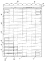
レンチキュラー・レンズ・シート5は、図示しない偏光板を介して液晶表示パネル4に積層されている。レンチキュラー・レンズ・シート5は、図1に示したように、平板状の基体51上に複数のレンズ52が周期的に配列された構造を有している。図2に液晶表示パネル4とレンチキュラー・レンズ・シート5の配置関係を説明するための図を示す。つまり、図2は液晶表示パネル4の平面図と表示ユニット2の断面図とを対応して示している。
図2において、前述した走査線41は液晶表示パネル4の水平方向に配線されており、信号線42は液晶表示パネル4の垂直方向に配線されている。そして、走査線41および信号線42で囲まれる領域が画素43を構成する。なお、図2においては、理解を容易にするために走査線41および信号線42は点線で示している。
図2に示すように、レンチキュラー・レンズ・シート5のレンズ51は、一対の長辺および一対の短辺とからなる画素43の短辺に沿って延びている。また、液晶表示パネル4とレンチキュラー・レンズ・シート5とは、液晶表示パネル4の走査線41間のピッチとレンチキュラー・レンズ・シート5のレンズ51間のピッチとが一致するように積層されている。つまり、レンチキュラー・レンズ・シート5の隣接するレンズ52,52境界が液晶表示パネル4の走査線41と重なるように配置される。最も望ましくは、前記境界と走査線41の幅方向中央とが一致するように配置する。レンチキュラー・レンズ・シート5の各レンズ52は、平行光が照射された場合に液晶表示パネル4の液晶層で焦点を結ぶように設計してある。通常、液晶表示パネル4を構成するアレイ基板とカラー・フィルタ基板とは、同一の厚さを有しているため、各レンズ52は、液晶表示パネル4の厚さ方向中央部で焦点を結ぶように設計されることになる。このような設計を採用する理由は追って説明する。なお、レンチキュラー・レンズ・シート5は、以上のような形状、寸法を除けば、従来公知の仕様を採用すればよい。
【0019】
図3にバックライト・ユニット3の斜視図を示す。バックライト・ユニット3は、光源であるランプ6と、ランプ6からの発光光を受光しかつ面状光として発光させるための導光板7と、ランプ6からの発光光を導光板7に効率よく供給するためのリフレクタ8と、導光板7の背面側に配置される反射板9と、プリズム・シート10とから構成される。なお、本発明において、導光板7の表示ユニット2に臨む側を表面側と、またその反対の側を背面側と定義する。
ランプ6には、熱陰極蛍光管あるいは冷陰極蛍光管が用いられる。導光板7は厚さ2〜3mm程度のアクリル樹脂、例えばポリメチルメタクリレートから構成される。導光板7のうち、ランプ6と対向する面を入光面と呼び、表示ユニット2と対向する面を発光面と呼ぶ。ランプ6からの発光光は、直接またはリフレクタ8から反射されて入光面から導光板に入光する。導光板7を全反射しながら進行する光は、導光板7の背面側に配置される反射板9によって導光板7の表面側に向けた面状光として発光する。リフレクタ8は、例えば、ステンレス鋼板あるいは黄銅板をプレス加工により図示の形状に形成し、その内面にAgをスパッタしたPETフィルムをラミネートすることにより構成される。反射板9としては、厚さ50μm程度のPET製粘着テープにAgあるいはAlを蒸着により被覆したもの、あるいは白色のフィルムを用いることができる。
【0020】
本実施の形態によるバックライト・ユニット3は、表示ユニット2に対して照射される光の集光度合いを高くするための工夫がなされている。具体的には、導光板7の表面側にプリズム71を形成し、さらに導光板7の表面側にプリズム・シート10を配置している。プリズム・シート10は、導光板7と表示ユニット2との間に存在することになる。導光板7に構成されたプリズム71は、その稜線がランプ6と直交するように形成される。つまり、導光板7内の光の進行方向に対して平行な方向に沿ってプリズム71は形成されている。プリズム71の頂角は、70°〜130°の範囲とすることが望ましい。プリズム71は導光板7の上面に設けても下面に設けてもかまわない。なお、プリズム・シート10は、その上面にプリズムを形成することもできる。また、プリズム・シート10は、その下面に稜線がランプ6と平行になるようにプリズムを形成している。つまり、プリズム・シート10のプリズムは、導光板7内の光の進行方向に対して垂直な方向に沿って形成されている。プリズム・シート10の頂角は、60°〜75°の範囲とすることが望ましい。本実施の形態によるバックライト・ユニット3は、ランプ6と平行な方向の集光を導光板7に形成したプリズム71が受け持ち、ランプ6と垂直な方向の集光をプリズム・シート10が受け持つ。ただし、このプリズム・シート10の集光は、導光板7が楔形形状をしているために生ずる全反射の崩壊によって前記発光面から出射してくる光を対象とする。
集光度合いの評価として、中央部を最大の輝度とし、輝度が最大輝度の半分になる角度(以下、半値幅という)を指標とすることが行われている。つまり、この半値幅が小さいほど集光度合いが強いことを示している。本実施の形態によるバックライト・ユニット3の半値幅を測定したところ、±10°であった。従来のバックライト・ユニットが±25°程度であったことから、本実施の形態によるバックライト・ユニット3は、集光度合いが相当向上したことが判明した。
【0021】
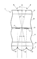
図4は、本実施の形態による液晶表示装置1において、バックライト・ユニット3を発光させたときの液晶表示パネル4における光の透過状態を示す断面模式図である。
図4に示すように、液晶表示パネル4は、図示しないバックライト・ユニット3の存在する図中下方から、レンチキュラー・レンズ・シート5、偏光板24、アレイ基板21、液晶層23、カラー・フィルタ基板22および偏光板25が積層した構造をなしている。アレイ基板21上には、走査線41が形成されている。走査線41の幅方向中心とレンチキュラー・レンズ・シート5のレンズ52,52の境界とが一致するように、レンチキュラー・レンズ・シート5の配置を設定してある。また、前述のように、レンチキュラー・レンズ・シート5のレンズ52は、液晶層23上で焦点を結ぶように設計されている。
図4は、バックライト・ユニット3から発光された平行光(点線で示す)がレンチキュラー・レンズ・シート5に対して照射された状態を示している。さて、レンチキュラー・レンズ・シート5のレンズ52に照射された光は、レンズ52により液晶層23内に存在する焦点上に収束される。液晶層23内に存在する焦点上で収束された光は、焦点、つまり液晶層23を通過するとカラー・フィルタ基板22内において角度をλ1もって拡散しながら進行する。
カラー・フィルタ基板22を透過した後に偏光板25から出射される際、放射角度はλ1より大きいλ2となる。つまり、カラー・フィルタ基板22および偏光板25は屈折率がおよそ1.5であるから、カラー・フィルタ基板22を透過して偏光板25から出射される光の放射角度λ2は、カラー・フィルタ基板22および偏光板25を透過する際の放射角度λ1よりも大きくなる。したがって、本実施の形態による液晶表示装置1は、液晶表示パネル4を斜め方向から見る場合でも、拡散板を用いることなく、所定の明るさを確保することができる。
図8は、レンチキュラー・レンズ・シート5を設けない場合の光の透過状況を示している。なお、図4と同一の部分には同一の符号を付してある。図8の例では、偏光板24に照射された光のうち一部は走査線41で遮蔽される。遮蔽されなかった他の光はカラー・フィルタ基板22および偏光板25を透過するが、偏光板25表面に対して垂直に出射するため、放射角度が広がるという効果を期待することができない。
【0022】
本実施の形態による液晶表示装置1は、拡散板を用いることなく、所定の明るさを確保することができるという利点の他に、従来の液晶表示装置に比べて輝度を向上することができるという利点を副次的に有している。以下、この輝度向上効果について説明する。
レンチキュラー・レンズ・シート5を備えていない従来の液晶表示装置は、図8に示したように、アレイ基板21を進行する光の一部は、アレイ基板21上に形成されている走査線41、信号線42等によって遮蔽されてしまう。つまり、アレイ基板21上に形成されている走査線41、信号線42等が液晶表示パネル4の光透過率を低減させていた。
これに対して本実施の形態による液晶表示装置1は、図4に示すように、液晶表示パネル4に入射された光がレンチキュラー・レンズ・シート5によって走査線41,41の間に収束されるから、走査線41によって遮蔽されることはない。現実の装置においては、製造誤差等によって走査線41によって遮蔽される可能性があるが、その場合でも従来の液晶表示装置に比べれば遮蔽される量はごく僅かである。したがって、従来の液晶表示装置に比べて輝度を向上することができるのである。
ここで、本実施の形態による液晶表示装置1は、前述したように、導光板7にプリズム71を設け、さらにプリズム・シート10を設けてバックライト・ユニット3から照射される光の集光度合いを高めている。これは、走査線41,41間を透過できずに走査線41にて遮蔽される可能性を低減するためである。この集光度合いは、半値幅で±5〜15°の範囲とすることが望ましい。±15°を超えると集光度合いが不足し、±5°未満では集光度合いが強すぎて偏光板25から出射される光の放射分布を十分に確保できなくなるおそれがあるからである。偏光板25から出射される光の半値幅については、±15〜30°とすることが望ましい。±15°未満では広い角度から見た場合の明るさが不足し、±30°を超えると正面の明るさが不足するためである。
【0023】
以上説明したように、本実施の形態による液晶表示装置1は、液晶表示パネル4の所定位置にレンチキュラー・レンズ・シート5を配置したため、拡散板を設けることなく、所定の広がりを持った出射光を得ることができる。しかも、アレイ基板21上の走査線41による遮光を防止することができるので、輝度をより向上することができる。
【0024】
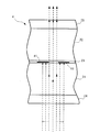
図4に示した例では、レンチキュラー・レンズ・シート5のレンズ52の焦点を液晶層23上で結ぶように設定したが、本発明はこの形態に限定されない。例えば、図5に示すように、レンズ52の焦点をアレイ基板21内で結ぶように設計してもよい。そして、図5から理解できるように、レンズ52の焦点をアレイ基板21内で結ぶように設計しても、図4で示した液晶表示装置1と同様の効果を得ることができる。
また、レンズ52の焦点は、図6に示すように、カラー・フィルタ基板22内でレンズ52の焦点を結ぶようにすることもできる。その場合でも、図6から理解できるように、図4で示した液晶表示装置1と同様の効果を得ることができる。
【0025】
さらに、図4で示した例では、レンチキュラー・レンズ・シート5のレンズ52,52の境界線が走査線41,41の幅方向中央に一致している。この図4の形態は最も望ましい形態であるが、本発明の効果を得るための必須の構成ではない。図7に示すように、レンズ52,52の境界線と走査線41,41の幅方向中央とがずれていても、図4と同様の効果を得ることができる。つまり、図7に示すように、レンズ52,52の境界線と走査線41,41の幅方向中央とがずれていても、レンズ52の焦点が、隣接する走査線41,41の間、つまり画素43の投影面の範囲内に存在すれば、本発明の効果を十分に享受することができる。逆に、レンズ52の焦点が、走査線41の投影面内に存在する場合には、走査線41がレンズ52を通過した光を遮蔽することになる。
【0026】
以上説明した実施の形態では、レンチキュラー・レンズ・シート5を偏光板24の下面に配置したが、アレイ基板21と偏光板24との間にレンチキュラー・レンズ・シート5を配置することもできる。ただし、この形態では、レンチキュラー・レンズ・シート5が、偏光板24による偏光をキャンセルしてはならない。本発明者等の検討によると、レンチキュラー・レンズ・シート5が紫外線硬化型樹脂で構成され、そのレンズ52の軸方向に対して平行に偏光が入射すれば、偏光のキャンセルは生じない。つまり、偏光板24の偏光方向とレンズ52の軸方向とを一致させれば良い。
また、本実施の形態による液晶表示装置1では、レンチキュラー・レンズ・シート5のレンズ52を画素43の短辺に沿って画素43の列に対応して形成した。しかし、レンズ52を画素43の長辺に沿って画素43の行に対応して形成することもできる。ただし、通常、液晶表示パネル4は、信号線42,42の間隔は走査線41,41の間隔の1/3しかない。そのため、画素43の行に対応したレンチキュラー・レンズ・シート5を設ける場合、製造の困難性の問題がある。したがって、本実施の形態のように、レンチキュラー・レンズ・シート5のレンズ52を画素43の短辺に沿って画素43の列に対応して形成することが望ましい。
【0027】
【発明の効果】
以上説明したように、本発明によれば、輝度を向上できるとともに、放射分布の広い光を出射させることのできる液晶表示パネルおよび液晶表示装置を提供することができる。
【図面の簡単な説明】
【図1】 本実施の形態による液晶表示装置の主要構成断面を示す図である。
【図2】 本実施の形態による液晶表示パネルとレンチキュラー・レンズ・シートの配置関係を説明するための図である。
【図3】 本実施の形態によるバックライト・ユニットの分解斜視図である。
【図4】 本実施の形態による液晶表示装置において、バックライト・ユニットを発光させたときの液晶表示パネルにおける光の透過状態を示す断面模式図である。
【図5】 本実施の形態による液晶表示装置の変形例を示す図である。
【図6】 本実施の形態による液晶表示装置の変形例を示す図である。
【図7】 本実施の形態による液晶表示装置の変形例を示す図である。
【図8】 本実施の形態による液晶表示装置の効果を説明するための図である。
【符号の説明】
1…液晶表示装置、2…表示ユニット、21…アレイ基板、22…カラー・フィルタ基板、23…液晶層、24,25…偏光板、3…バックライト・ユニット、4…液晶表示パネル、41…走査線、42…信号線、43…画素、5…レンチキュラー・レンズ・シート、51…基体、52…レンズ、6…ランプ、7…導光板、71…プリズム、8…リフレクタ、9…反射板、10…プリズム・シート[0001]
BACKGROUND OF THE INVENTION
The present invention relates to a liquid crystal display device suitable for a portable personal computer (PC).
[0002]
[Prior art]
As an image display device for a PC and other various monitors, a liquid crystal display device has been widely used. In this type of liquid crystal display device, generally, a backlight, which is a planar light source for illumination, is disposed on the back of a liquid crystal display panel, and a liquid crystal layer having a predetermined spread is irradiated with uniform brightness as a whole. The image formed on the liquid crystal layer is configured to be visualized.
This backlight employs a hot cathode or cold cathode fluorescent lamp as a light source, and it is necessary to irradiate the entire surface of the liquid crystal display panel with light from a so-called linear light source using these fluorescent tubes. Conventionally, two types (edge light type) have been adopted. In this direct type backlight unit, a fluorescent tube is placed directly under a liquid crystal display panel, and a light control plate and a diffusion plate are installed thereon. On the other hand, in the sidelight type, a fluorescent tube is installed on two or one side of a transparent resin light guide plate, and the light incident on the light guide plate is processed on the back surface of the light guide plate by the reflective part in the direction of the liquid crystal display panel surface. For this purpose, a uniform planar light is provided using a diffusion plate. A sidelight-type backlight can be made thinner than a direct-type backlight, and thus is suitable for a display device of a portable device such as a notebook PC.
[0003]
A characteristic required for a liquid crystal display device is that a bright screen can be seen even from a wide angle.
In order to brighten the screen, increasing the brightness of the backlight is the most effective method, but it has a drawback of increasing the power consumption. In particular, in the case of a portable device, since it is assumed that a built-in battery is used, there is a place where it is difficult to adopt a method of brightening the screen by improving the characteristics of the backlight.
Conventionally, a liquid crystal display device uses a diffusion plate as an element for viewing a bright screen even from a wide angle. The diffuser plate emits light emitted from the light guide plate as light having a wider radiation distribution from the image display surface, so that the screen can be recognized brightly even when viewed from a wide angle.
[0004]
[Problems to be solved by the invention]
As will be described in detail later, the diffuser plate is an element that reduces the amount of transmitted light. Therefore, the luminance of the liquid crystal display device can be improved by removing the diffusion plate. However, since the diffusion plate plays an important role of making the screen brightly recognized even when viewed from a wide angle, it has been difficult to remove the diffusion plate in practice.
Accordingly, it is an object of the present invention to provide a liquid crystal display panel and a liquid crystal display device that can improve luminance and increase the radiation distribution of light emitted from the liquid crystal display panel.
[0005]
[Means for Solving the Problems]
As described above, it is conceivable to remove the diffusion plate as one technique for improving the luminance of the liquid crystal display device. The diffusing plate has a structure in which a light diffusing layer made of a light transmissive resin and light scattering particles such as acrylic particles and silica particles is formed on the surface of a transparent substrate such as a PET film. Therefore, when the light emitted from a light source such as a fluorescent tube passes through the diffusion plate, the luminance is at least lowered. That is, the luminance of the liquid crystal display device can be improved by removing the diffusion plate that causes the luminance to decrease. However, if the diffusing plate is removed, it becomes impossible to irradiate the liquid crystal display panel with uniform planar light, and thus the diffusing plate cannot be simply removed.
[0006]
The diffuser plate plays a role of supplying light having a wide radiation distribution to the liquid crystal display panel. That is, it is the diffusion plate that gives the light a predetermined spread before entering the liquid crystal display panel. However, it is not essential for the liquid crystal display device to have a predetermined spread before entering the liquid crystal display panel. The emitted light emitted from the liquid crystal display panel only needs to have a predetermined spread. The liquid crystal display panel has a structure in which two glass substrates having a thickness of about 0.7 mm are stacked with a liquid crystal layer filled with a liquid crystal material as an optical element interposed therebetween. Here, in a TFT (Thin Film Transistor) type liquid crystal display device which is mainly used as a color liquid crystal display device, one glass substrate constitutes an array substrate, and the other glass substrate constitutes a color filter substrate. Polarizing plates are laminated on the surfaces of the array substrate and the color filter substrate, respectively. The light from the backlight is sequentially transmitted through the polarizing plate, the array substrate, the color filter substrate, and the polarizing plate, and then emitted to the outside. Therefore, when the light is emitted from the polarizing plate laminated on the color filter substrate and can be emitted as light having a wide radiation distribution, the diffusion plate may be removed.
Since the refractive index of the polarizing plate laminated on the color filter substrate is different from that of air, if the light emitted from the polarizing plate has an angle with respect to the emission surface, it can be emitted as light having a wide radiation distribution. It becomes possible.
[0007]
In order to realize the light passing behavior as described above, the present invention proposes to use a light converging means, for example, a lenticular lens. That is, for example, a lenticular lens having a focal point on the liquid crystal layer is disposed on the light incident surface side of the array substrate, and the light emitted from the backlight unit is passed through the lenticular lens, thereby allowing the inside of the liquid crystal display panel, For example, it converges on the liquid crystal layer. The light converged on the liquid crystal layer diffuses at a predetermined angle when passing through the color filter substrate, and when emitted from the polarizing plate, due to the difference in refractive index with air, It is emitted as light of a wider angle.
[0008]
Converging on the liquid crystal layer brings about the following brightness enhancement effect as a secondary effect. Wirings such as TFTs, signal lines for driving the TFTs, and scanning lines are formed on the array substrate. These serve as a light-shielding portion that prevents light transmission in the liquid crystal display panel. As the definition of a liquid crystal display device increases, the ratio of TFTs, signal lines, and scanning lines occupying a certain area increases, so that the area of the light transmitting portion, that is, the aperture ratio decreases. A decrease in the aperture ratio causes a decrease in the luminance of the liquid crystal display device. Ideally, if the light emitted from the backlight escapes the light-shielding portions such as TFTs, signal lines, and scanning lines and passes through the liquid crystal display panel, the brightness is theoretically lowered even if the aperture ratio is lowered. There is nothing.
If a lenticular lens is used as described above, light can be converged on the liquid crystal layer. If this convergence position is set, for example, between adjacent scanning lines, that is, within a pixel, the amount of light blocked by the scanning lines can be emitted from the liquid crystal display panel. Assuming that the brightness is higher than that of the conventional liquid crystal display device.
[0009]
The liquid crystal display panel of the present invention is based on the above examination results and knowledge, and is a display panel used for a direct-view display device including an optical element that controls light emitted from a light source, and is light transmissive. A first substrate configured to receive light emitted from the light source and configured to receive light transmitted from the first substrate and transmitted from the image display surface; A second substrate that emits light; an optical element layer that is disposed between the first substrate and the second substrate and that is filled with the optical element; and light that is emitted from the light source. And a light converging means for converging on the display panel.
The display panel of the present invention includes light converging means for converging light emitted from the light source onto the optical element layer. The light converged on the optical element layer is diffused at a predetermined angle in the process of passing through the second substrate after passing through the optical element layer, and from the second substrate at an angle wider than the predetermined angle. Can be emitted. That is, since a light having a wide radiation distribution can be emitted from the display panel without using a diffusion plate as in the prior art, the luminance can be improved and the screen can be recognized brightly even when viewed from a wide angle. In addition, if the position of convergence by the light converging means is appropriately set, it is possible to partially avoid the light shielding by the light shielding unit described above.
[0010]
When the display panel of the present invention includes a plurality of pixels arranged in a dot matrix, the light converging means can be formed corresponding to the columns or rows of the pixels. A configuration in which a lenticular lens is provided for each pixel column or pixel row is applicable.
In addition to the lenticular lens, a compound eye lens can also be used as the light focusing means of the present invention.
In the above display panel of the present invention, in the case of the liquid crystal display panel described above, the first substrate includes a polarizing plate and an array substrate, and the second substrate includes a polarizing plate and a color filter substrate. It is a concept.
[0011]
A typical application example of the display panel of the present invention is a liquid crystal display device. Accordingly, the present invention provides an array substrate in which rectangular pixels having a pair of long sides and a pair of short sides are formed in a matrix, and a color filter substrate disposed to face the array substrate with a predetermined gap therebetween. A liquid crystal display panel having a liquid crystal layer located in the gap and a plurality of lenticular lenses extending along the short side, wherein the lenticular lens has light emitted from a light source by the array substrate. A liquid crystal display panel is provided, wherein the lenticular lens is arranged so that a boundary between adjacent lenticular lenses is along a short side of the pixel.
In the liquid crystal display panel of the present invention, the lenticular lens receives light from the light source. The light is converged between the array substrate and the color filter substrate by the lenticular lens, but is transmitted through the color filter substrate while diffusing at a predetermined angle. Light that is transmitted to the outside after passing through the color filter substrate and further passing through the polarizing plate that is normally provided in the liquid crystal display panel has a wide radiation distribution due to the difference in refractive index from air. Therefore, the same effect as that provided with the diffusion plate can be obtained without providing the diffusion plate.
[0012]
In the liquid crystal display panel of the present invention, it is preferable that the lenticular lens is focused on the optical element layer. In the liquid crystal display panel of the present invention, it is preferable that the lenticular lens is focused within the range of the projection surface of the pixel. By adopting such a lens design, it is possible to prevent light from being shielded by the scanning lines formed on the array substrate. That is, the luminance of the liquid crystal display panel can be improved regardless of the aperture ratio.
Furthermore, the liquid crystal display panel of the present invention is applied to a direct-view type liquid crystal display device. In this case, the distance between a pair of short sides in the pixel is set in the range of 100 to 300 μm.
[0013]
The present invention also provides a liquid crystal display device using the above liquid crystal display panel. That is, the liquid crystal display device of the present invention includes a liquid crystal display panel including a liquid crystal layer and having an image display surface, a light source for irradiating the liquid crystal display panel with light, the liquid crystal display panel, and the light source. And a lens for converging light emitted from the light source in the liquid crystal display panel, and the light emitted from the light source has a first angle after converging in the liquid crystal display panel. And the light is emitted from the image display surface at a second angle larger than the first angle.
Therefore, according to the liquid crystal display panel of the present invention, it is possible to emit light having a wide radiation distribution without providing a diffusion plate.
[0014]
In the liquid crystal display device according to the aspect of the invention, if the lens is configured such that the light emitted from the light source converges at or near the liquid crystal layer, the light emitted from the light source is at or near the liquid crystal layer. Then, the light is diffused with a first angle and then emitted from the image display surface at a second angle larger than the first angle.
Further, according to the liquid crystal display device of the present invention, the half-value width of the light emitted from the image display surface can be made larger than the half-value width of the light emitted from the light source.
Moreover, according to the liquid crystal display device of the present invention, it is desirable that the half-value width of the light emitted from the light source is ± 5 to 15 °.
Furthermore, according to the liquid crystal display device of the present invention, it is desirable that the half width of the light emitted from the image display surface is ± 15 to 30 °.
As a more specific structure of the liquid crystal display device of the present invention, a light guide plate that guides light emitted from the light source to the liquid crystal display panel and forms a prism structure on the light output surface thereof, the light guide plate, and the liquid crystal display panel And a prism sheet having a prism structure that intersects the prism structure formed on the light guide plate on a surface desired as a light exit surface of the light guide plate, and the prism sheet of the liquid crystal display panel It is desirable that the liquid crystal display panel further includes no lens structure on the image display surface side. Furthermore, it is preferable that the prism structure of the light guide plate is formed along a light traveling direction in the light guide plate.
[0015]
The present invention provides the following liquid crystal display device. That is, the present invention provides an array substrate in which a plurality of signal lines for supplying a display signal and a plurality of scanning lines for supplying a scanning signal are arranged in a matrix, and a predetermined gap from the array substrate. A liquid crystal display panel having a color filter substrate disposed oppositely and a liquid crystal layer positioned in the gap, and provided on the back surface of the liquid crystal display panel and entering light from at least one light incident surface and the light incident surface A light guide plate having a light emitting surface for emitting light, a lamp disposed along a light incident surface of the light guide plate, and provided between the light guide plate and the liquid crystal display panel and on the scanning line And a plurality of lenticular lenses extending in parallel directions.
In the liquid crystal display device of the present invention, the light emitted from the lamp is applied to the lenticular lens through the light guide plate. The light irradiated to the lenticular lens converges within the range of the array substrate to the color filter substrate. The light once converged is diffused at a predetermined angle, transmitted through the color filter substrate, and then emitted to the outside of the liquid crystal display panel. At this time, due to the difference in refractive index between the liquid crystal display panel and air, the emitted light is emitted at a wider angle.
[0016]
In the liquid crystal display device of the present invention, it is desirable that the arrangement pitch of the plurality of lenticular lenses and the arrangement pitch of the plurality of scanning lines coincide with each other.
In the liquid crystal display device of the present invention, a plurality of first prisms extending in a direction parallel to the light traveling direction in the light guide plate are formed on the light emitting surface of the light guide plate, and the light guide plate It is desirable to dispose a prism sheet formed with a plurality of second prisms extending in a direction perpendicular to the light traveling direction in the light guide plate between the lenticular lens. This is to improve the concentration of light irradiated to the lenticular lens.
[0017]
DETAILED DESCRIPTION OF THE INVENTION
Hereinafter, the present invention will be described based on embodiments.
FIG. 1 shows a cross section of a main configuration of a liquid
The liquid
The
[0018]
The
In FIG. 2, the
As shown in FIG. 2, the
[0019]
FIG. 3 shows a perspective view of the
The lamp 6 is a hot cathode fluorescent tube or a cold cathode fluorescent tube. The light guide plate 7 is made of an acrylic resin having a thickness of about 2 to 3 mm, for example, polymethyl methacrylate. Of the light guide plate 7, the surface facing the lamp 6 is called a light incident surface, and the surface facing the
[0020]
The
As an evaluation of the degree of light collection, the central portion is set to the maximum luminance, and an angle at which the luminance becomes half of the maximum luminance (hereinafter referred to as half width) is used as an index. That is, the smaller the half-value width, the stronger the degree of light collection. When the half width of the
[0021]
FIG. 4 is a schematic cross-sectional view showing a light transmission state in the liquid
As shown in FIG. 4, the liquid
FIG. 4 shows a state in which parallel light (shown by a dotted line) emitted from the
When the light is emitted from the
FIG. 8 shows a light transmission state when the
[0022]
The liquid
As shown in FIG. 8, in the conventional liquid crystal display device that does not include the
In contrast, in the liquid
Here, as described above, in the liquid
[0023]
As described above, in the liquid
[0024]
In the example shown in FIG. 4, the focus of the
Further, as shown in FIG. 6, the
[0025]
Furthermore, in the example shown in FIG. 4, the boundary line of the
[0026]
In the embodiment described above, the
In the liquid
[0027]
【The invention's effect】
As described above, according to the present invention, it is possible to provide a liquid crystal display panel and a liquid crystal display device that can improve luminance and emit light having a wide radiation distribution.
[Brief description of the drawings]
FIG. 1 is a diagram showing a cross section of a main configuration of a liquid crystal display device according to an embodiment.
FIG. 2 is a diagram for explaining an arrangement relationship between a liquid crystal display panel and a lenticular lens sheet according to the present embodiment.
FIG. 3 is an exploded perspective view of a backlight unit according to the present embodiment.
FIG. 4 is a schematic cross-sectional view showing a light transmission state in a liquid crystal display panel when a backlight unit emits light in the liquid crystal display device according to the present embodiment.
FIG. 5 is a diagram showing a modification of the liquid crystal display device according to the present embodiment.
FIG. 6 is a diagram showing a modification of the liquid crystal display device according to the present embodiment.
FIG. 7 is a diagram showing a modification of the liquid crystal display device according to the present embodiment.
FIG. 8 is a diagram for explaining the effect of the liquid crystal display device according to the present embodiment;
[Explanation of symbols]
DESCRIPTION OF
Claims (13)
光透過性材料から構成され、かつ前記光源から照射される光を受光する第1の基板と、
光透過性材料から構成され、かつ前記第1の基板を透過した光を受光するとともに、この画像表示面から前記光が出射する第2の基板と、
前記第1の基板および前記第2の基板の間に配置され、かつ前記光学素子が満たされた光学素子層と、
前記光源から照射された光を前記光学素子層上に収束させる複数のレンチキュラー・レンズと、を備え、
前記第1の基板は、表示信号を供給するための複数の信号線と、走査信号を供給するための複数の走査線とを有し、
前記複数のレンチキュラー・レンズによって収束された光は、隣り合う信号線間の領域内又は隣り合う走査線間の領域内に到達して前記光学素子層を透過し、
各レンチキュラー・レンズは、少なくとも1つの隣り合うレンチキュラー・レンズと、これらレンズ曲面が連続するように構成されていることを特徴とする表示パネル。A display panel used in a direct-view display device including an optical element that controls light emitted from a light source,
A first substrate for receiving is configured from a light transmissive material, and the light emitted from the light source,
Is composed of a light transmitting material, and while receiving the light transmitted through the first substrate, a second substrate on which the light from the image display surface of this is emitted,
An optical element layer disposed, and the optical element is filled between the first substrate and the second substrate,
A plurality of lenticular lenses that converge the light emitted from the light source onto the optical element layer, and
The first substrate has a plurality of signal lines for supplying a display signal and a plurality of scanning lines for supplying a scanning signal,
The light converged by the plurality of lenticular lenses reaches the area between adjacent signal lines or the area between adjacent scanning lines and passes through the optical element layer,
Display panel each lenticular lens, which is characterized with at least one adjacent lenticular lenses, that these curved lens surface is configured so as to be continuous.
前記アレイ基板と所定の間隙を隔てて対向配置されるカラー・フィルタ基板と、
前記間隙に位置する液晶層と、
前記短辺に沿って延びる複数のレンチキュラー・レンズと、を備えた直視型の液晶表示パネルであって、
前記レンチキュラー・レンズは、前記アレイ基板が光源からの光を受ける面側に配置され、かつ隣接する前記レンチキュラー・レンズ同士の境界が前記画素の前記短辺に沿うように配置されており、
前記レンチキュラー・レンズは、この焦点を前記画素の投影面の範囲内で結び、各レンチキュラー・レンズは、少なくとも1つの隣り合うレンチキュラー・レンズと、これらレンズ曲面が連続するように構成されていることを特徴とする液晶表示パネル。An array substrate in which rectangular pixels having a pair of long sides and a pair of short sides are formed in a matrix;
A color filter substrate disposed opposite to the array substrate with a predetermined gap therebetween;
A liquid crystal layer located in the gap;
A direct-view liquid crystal display panel comprising a plurality of lenticular lenses extending along the short side,
The lenticular lens, the array substrate is placed on the side for receiving light from the light source, and the boundary of the lenticular lens and adjacent are arranged along the short side of the pixel,
The lenticular lens is focused in this within the projection plane of the pixels, each lenticular lens, and at least one adjacent lenticular lenses, that these curved lens surface is configured so as to be continuous A liquid crystal display panel characterized by
前記液晶表示パネルに対して光を照射するための光源と、
前記液晶表示パネルと前記光源との間に配置され、かつ前記光源から照射された光を前記液晶表示パネル内で収束させるレンズと、を備え、
前記液晶表示パネルは、前記光源から照射された光が、該液晶表示パネル内で収束した後に第1の角度を持って拡散し、かつ前記第1の角度より大きい第2の角度で前記画像表示面から出射するように構成されており、
前記光源から照射される光の半値幅が、−15〜−5°又は5〜15°の範囲内であることを特徴とする液晶表示装置。A liquid crystal display panel including a liquid crystal layer and having an image display surface;
A light source for irradiating the liquid crystal display panel with light;
Wherein disposed between the liquid crystal display panel and the light source, and includes a lens for converging the emitted light in the liquid crystal display panel from the light source,
The liquid crystal display panel, the light emitted from the light source, diffused with a first angle after convergence in the liquid crystal display panel, and the image display in the first angle is greater than the second angle Configured to exit from the surface,
The liquid crystal display device, wherein a half width of light emitted from the light source is in a range of −15 to −5 ° or 5 to 15 °.
前記液晶表示パネルに対して光を照射するための光源と、
前記液晶表示パネルと前記光源との間に配置され、かつ前記光源から照射された光を前記液晶表示パネル内で収束させるレンズと、を備え、
前記液晶表示パネルは、前記光源から照射された光が、前記液晶表示パネル内で収束した後に第1の角度を持って拡散し、かつ前記第1の角度より大きい第2の角度で前記画像表示面から出射するように構成されており、
前記画像表示面から出射される光の半値幅が、−30〜−15°又は15〜30°の範囲内であることを特徴とする液晶表示装置。A liquid crystal display panel including a liquid crystal layer and having an image display surface;
A light source for irradiating the liquid crystal display panel with light;
Wherein disposed between the liquid crystal display panel and the light source, and includes a lens for converging the emitted light in the liquid crystal display panel from the light source,
The liquid crystal display panel, the light emitted from the light source, diffused with a first angle after focusing in the liquid crystal display panel, and the image display in the first angle is greater than the second angle Configured to exit from the surface,
Half-width of the light emitted from the image display surface, the liquid crystal display device, characterized in that in the range of -30 to-15 ° or 15 to 30 °.
前記液晶表示パネルの背面に設けられ、かつ少なくとも1つの入光面および前記入光面から入光した光が発光するための発光面を備えた導光板と、
前記導光板の入光面に沿って配置されたランプと、
前記導光板と前記液晶表示パネルとの間に設けられ、かつ前記走査線に平行な方向に延びる複数のレンチキュラー・レンズと、を備え、
前記複数のレンチキュラー・レンズの配列ピッチと前記複数の走査線の配列ピッチとが一致し、
前記複数のレンチキュラー・レンズは、隣り合う信号線間の領域内又は隣り合う走査線間の領域内に向けて、前記ランプからの光を収束させ、該光が前記液晶表示パネルを透過することを特徴とする液晶表示装置。An array substrate in which a plurality of signal lines for supplying display signals and a plurality of scanning lines for supplying scanning signals are arranged in a matrix, and a color arranged to face the array substrate with a predetermined gap therebetween A liquid crystal display panel having a filter substrate and a liquid crystal layer positioned in the gap;
And the liquid crystal provided on the rear surface of the display panel, and at least one light incident surface and the entering light guide plate having a light emitting surface of the light is emitted to the incident from the light incident surface,
A lamp disposed along a light incident surface of the light guide plate;
The light guide plate and the provided between the liquid crystal display panel, and includes a plurality of lenticular lenses extending in a direction parallel to the scan lines,
The arrangement pitch of the plurality of lenticular lenses and the arrangement pitch of the plurality of scanning lines match ,
The plurality of lenticular lenses converge light from the lamp toward an area between adjacent signal lines or an area between adjacent scanning lines, and the light passes through the liquid crystal display panel. A characteristic liquid crystal display device.
前記導光板と前記レンチキュラー・レンズとの間に、前記導光板内における光の進行方向に対して垂直な方向に延びる第2のプリズムを複数形成したプリズム・シートが配置されていることを特徴とする請求項11に記載の液晶表示装置。Wherein the light emitting surface of the light guide plate, a first prism extending in a direction parallel to the traveling direction of light in the light guide plate is formed with a plurality,
And wherein the light guide plate and between the lenticular lens, a prism sheet in which a plurality forming a second prism extending in a direction perpendicular to the traveling direction of light in the light guide plate is arranged The liquid crystal display device according to claim 11.
前記複数のレンチキュラー・レンズの配列ピッチと前記複数の走査線の配列ピッチとが一致することを特徴とする請求項1に記載の表示パネル。 The signal lines and scanning lines are arranged in a matrix,
The display panel according to claim 1, wherein an arrangement pitch of the plurality of lenticular lenses and an arrangement pitch of the plurality of scanning lines coincide with each other.
Applications Claiming Priority (2)
| Application Number | Priority Date | Filing Date | Title |
|---|---|---|---|
| US10/144996 | 2002-05-14 | ||
| US10/144,996 US6791639B2 (en) | 2002-05-14 | 2002-05-14 | Direct view display with lenticular lens for improved brightness and wide viewing angle |
Publications (2)
| Publication Number | Publication Date |
|---|---|
| JP2003330007A JP2003330007A (en) | 2003-11-19 |
| JP3860558B2 true JP3860558B2 (en) | 2006-12-20 |
Family
ID=29418579
Family Applications (1)
| Application Number | Title | Priority Date | Filing Date |
|---|---|---|---|
| JP2003133517A Expired - Lifetime JP3860558B2 (en) | 2002-05-14 | 2003-05-12 | Display panel, liquid crystal display panel, and liquid crystal display device |
Country Status (2)
| Country | Link |
|---|---|
| US (1) | US6791639B2 (en) |
| JP (1) | JP3860558B2 (en) |
Families Citing this family (57)
| Publication number | Priority date | Publication date | Assignee | Title |
|---|---|---|---|---|
| JP2003150073A (en) * | 2001-08-27 | 2003-05-21 | Omron Corp | Image display unit and front light |
| KR100962650B1 (en) * | 2003-03-05 | 2010-06-11 | 삼성전자주식회사 | Optical sheet and liquid crystal display apparatus using the same |
| JP2005071610A (en) * | 2003-06-26 | 2005-03-17 | Toyota Industries Corp | Light guide plate and plane light source device |
| TWI325076B (en) * | 2004-02-27 | 2010-05-21 | Sharp Kk | Display apparatus |
| TW200602585A (en) * | 2004-03-16 | 2006-01-16 | Koninkl Philips Electronics Nv | High brightness illumination device with incoherent solid state light source |
| TWM261716U (en) * | 2004-07-09 | 2005-04-11 | Entire Technology Co Ltd | Highly uniformly light-emitting bottom lighting back light module structure |
| TWI275874B (en) * | 2004-08-06 | 2007-03-11 | Hon Hai Prec Ind Co Ltd | Light guiding device and backlight module using the same |
| JP2006171718A (en) * | 2004-12-16 | 2006-06-29 | Samsung Electronics Co Ltd | Light diffusing member, backlight assembly having the same, and display apparatus having the same |
| US7113342B2 (en) * | 2005-02-24 | 2006-09-26 | Pong & Huang International Co., Ltd. | Composite structure for light diffusion |
| US8192067B2 (en) * | 2005-03-01 | 2012-06-05 | Sharp Kabushiki Kaisha | Backlight unit and liquid crystal display apparatus having light guiding member, prism sheet and reflection section |
| KR100742242B1 (en) | 2005-03-04 | 2007-07-25 | (주)포스미디어 | Backlight unit for lcd |
| US7295262B2 (en) * | 2005-04-08 | 2007-11-13 | Rohm And Haas Denmark Finance A/S | Display apparatus having collimated illumination |
| KR20070001474A (en) * | 2005-06-29 | 2007-01-04 | 엘지.필립스 엘시디 주식회사 | Back light unit |
| JP4868798B2 (en) * | 2005-08-31 | 2012-02-01 | 東芝モバイルディスプレイ株式会社 | Liquid crystal display device and method of manufacturing liquid crystal display device |
| JP4500321B2 (en) * | 2007-03-05 | 2010-07-14 | 株式会社 日立ディスプレイズ | Liquid crystal display |
| GB0704803D0 (en) * | 2007-03-13 | 2007-04-18 | Cambridge Flat Projection | Structured colour illumination of lcd's |
| TWI334046B (en) * | 2007-07-10 | 2010-12-01 | Au Optronics Corp | Color filterless liquid crystal display device |
| JP2009258582A (en) * | 2007-09-05 | 2009-11-05 | Toshiba Corp | Three-dimensional image display device, method and device for manufacturing three-dimensional image display device, and apparatus for manufacturing the three-dimensional image display device |
| JP4566226B2 (en) * | 2007-09-07 | 2010-10-20 | 株式会社 日立ディスプレイズ | Liquid crystal display |
| JP4642823B2 (en) * | 2007-09-13 | 2011-03-02 | 株式会社日立製作所 | Illumination device and liquid crystal display device |
| KR101275963B1 (en) * | 2007-10-24 | 2013-06-14 | 엘지디스플레이 주식회사 | Liquid crystal display device and method of manufacturing the same |
| WO2009081534A1 (en) * | 2007-12-21 | 2009-07-02 | Sharp Kabushiki Kaisha | Liquid crystal display panel, liquid crystal display device and manufacturing method of liquid crystal display panel |
| JP5176204B2 (en) * | 2008-04-07 | 2013-04-03 | Nltテクノロジー株式会社 | Liquid crystal panel and manufacturing method thereof |
| WO2009141953A1 (en) * | 2008-05-20 | 2009-11-26 | シャープ株式会社 | Liquid crystal display device |
| KR101565934B1 (en) * | 2008-05-23 | 2015-11-06 | 삼성디스플레이 주식회사 | Back-light assembly and display apparatus having the back-light assembly |
| US8004759B2 (en) * | 2009-02-02 | 2011-08-23 | Microsoft Corporation | Diffusing screen |
| CN102713742A (en) * | 2010-01-07 | 2012-10-03 | 株式会社东芝 | Display device and light source device |
| JP5197782B2 (en) * | 2011-03-04 | 2013-05-15 | 株式会社東芝 | Backlight device and display device |
| US9470882B2 (en) * | 2011-04-25 | 2016-10-18 | Cree, Inc. | Optical arrangement for a solid-state lamp |
| TWI475298B (en) * | 2012-05-23 | 2015-03-01 | 逢甲大學 | Time - based energy - saving color separation system |
| KR101418641B1 (en) * | 2012-06-22 | 2014-07-10 | 성지용 | Indoor or outdoor liquid crystal display including an led light source for improving a luminance |
| KR20140021748A (en) * | 2012-08-09 | 2014-02-20 | 삼성디스플레이 주식회사 | Lighting unit for display device and display device including lighting unit |
| US9230459B2 (en) | 2012-11-29 | 2016-01-05 | Dell Products L.P. | Ambience reflective display frame |
| JP6249273B2 (en) * | 2013-09-09 | 2017-12-20 | 大日本印刷株式会社 | Illuminated mirror device |
| JP6743372B2 (en) * | 2015-11-19 | 2020-08-19 | 大日本印刷株式会社 | Light wide-angle irradiation device |
| WO2018208619A1 (en) | 2017-05-08 | 2018-11-15 | Reald Spark, Llc | Optical stack for directional display |
| TW201921060A (en) | 2017-09-15 | 2019-06-01 | 美商瑞爾D斯帕克有限責任公司 | Optical stack for switchable directional display |
| WO2019090246A1 (en) | 2017-11-06 | 2019-05-09 | Reald Spark, Llc | Privacy display apparatus |
| EP3743766A4 (en) | 2018-01-25 | 2021-12-22 | RealD Spark, LLC | Touch screen for privacy display |
| JP7291444B2 (en) | 2018-01-25 | 2023-06-15 | リアルディー スパーク エルエルシー | Display device and viewing angle control optical element |
| CN112075076B (en) * | 2018-03-22 | 2023-05-02 | 瑞尔D斯帕克有限责任公司 | Light guide for directional backlight |
| US11079645B2 (en) | 2018-06-29 | 2021-08-03 | Reald Spark, Llc | Stabilization for privacy display |
| US11073735B2 (en) | 2018-07-18 | 2021-07-27 | Reald Spark, Llc | Optical stack for switchable directional display |
| TWI685700B (en) * | 2018-08-14 | 2020-02-21 | 友達光電股份有限公司 | Display device and pixel structure |
| CN113508334A (en) | 2019-01-07 | 2021-10-15 | 瑞尔D斯帕克有限责任公司 | Optical stack for privacy displays |
| CN113646695A (en) | 2019-02-12 | 2021-11-12 | 瑞尔D斯帕克有限责任公司 | Diffuser for a privacy display |
| TW202102883A (en) | 2019-07-02 | 2021-01-16 | 美商瑞爾D斯帕克有限責任公司 | Directional display apparatus |
| CN114730549A (en) | 2019-10-02 | 2022-07-08 | 瑞尔D斯帕克有限责任公司 | Privacy display device |
| US11733578B2 (en) | 2019-11-13 | 2023-08-22 | ReaID Spark, LLC | Display device with uniform off-axis luminance reduction |
| WO2021118936A1 (en) | 2019-12-10 | 2021-06-17 | Reald Spark, Llc | Control of reflections of a display device |
| EP4143041A1 (en) | 2020-04-30 | 2023-03-08 | RealD Spark, LLC | Directional display apparatus |
| CN115997146A (en) | 2020-04-30 | 2023-04-21 | 瑞尔D斯帕克有限责任公司 | Directional display device |
| US11506939B2 (en) | 2020-04-30 | 2022-11-22 | Reald Spark, Llc | Directional display apparatus |
| EP4189285A1 (en) | 2020-07-29 | 2023-06-07 | RealD Spark, LLC | Backlight for switchable directional display |
| TW202204818A (en) | 2020-07-29 | 2022-02-01 | 美商瑞爾D斯帕克有限責任公司 | Pupillated illumination apparatus |
| US11892717B2 (en) | 2021-09-30 | 2024-02-06 | Reald Spark, Llc | Marks for privacy display |
| WO2023196440A1 (en) | 2022-04-07 | 2023-10-12 | Reald Spark, Llc | Directional display apparatus |
Family Cites Families (18)
| Publication number | Priority date | Publication date | Assignee | Title |
|---|---|---|---|---|
| US35704A (en) * | 1862-06-24 | Improvement in piano-fortes | ||
| CA1312320C (en) | 1987-11-12 | 1993-01-05 | Makoto Oe | Plane light source unit |
| US4798448A (en) * | 1988-02-16 | 1989-01-17 | General Electric Company | High efficiency illumination system for display devices |
| JPH03170911A (en) * | 1989-11-30 | 1991-07-24 | Pioneer Electron Corp | Liquid crystal display device |
| EP0450780A3 (en) * | 1990-04-05 | 1992-04-15 | Matsushita Electric Industrial Co., Ltd. | Optical microelement array and its production method |
| US5280371A (en) * | 1992-07-09 | 1994-01-18 | Honeywell Inc. | Directional diffuser for a liquid crystal display |
| JP3006306B2 (en) * | 1992-09-16 | 2000-02-07 | インターナショナル・ビジネス・マシーンズ・コーポレイション | Optical film and liquid crystal display device using the optical film |
| US5561538A (en) * | 1992-11-17 | 1996-10-01 | Sharp Kabushiki Kaisha | Direct-view display apparatus |
| US5863113A (en) * | 1993-06-22 | 1999-01-26 | Mitsubishi Rayon Co., Ltd. | Plane light source unit |
| CA2099067C (en) * | 1993-06-23 | 2001-02-13 | Makoto Oe | Plane light source unit |
| US5598281A (en) * | 1993-11-19 | 1997-01-28 | Alliedsignal Inc. | Backlight assembly for improved illumination employing tapered optical elements |
| JP2950219B2 (en) * | 1995-10-13 | 1999-09-20 | オムロン株式会社 | Surface light source device, image display device using the surface light source device, and prism array used for the surface light source device |
| US5926601A (en) * | 1996-05-02 | 1999-07-20 | Briteview Technologies, Inc. | Stacked backlighting system using microprisms |
| JP3769327B2 (en) * | 1996-07-23 | 2006-04-26 | 大日本印刷株式会社 | Prism lens sheet, backlight system and liquid crystal display device |
| US6086212A (en) * | 1997-09-08 | 2000-07-11 | Kuraray Co., Ltd. | Panel light source device and display comprising it |
| JP4060441B2 (en) * | 1998-05-22 | 2008-03-12 | 東芝松下ディスプレイテクノロジー株式会社 | Flat panel display |
| US6164790A (en) * | 1998-12-17 | 2000-12-26 | Lg. Philips Lcd Co., Ltd. | Back light unit for a liquid crystal display device |
| US6600528B2 (en) * | 2000-12-19 | 2003-07-29 | International Business Machines Corporation | Integrated prism sheet for improved viewing angle in direct view color filterless liquid crystal displays |
-
2002
- 2002-05-14 US US10/144,996 patent/US6791639B2/en not_active Expired - Lifetime
-
2003
- 2003-05-12 JP JP2003133517A patent/JP3860558B2/en not_active Expired - Lifetime
Also Published As
| Publication number | Publication date |
|---|---|
| US20030214615A1 (en) | 2003-11-20 |
| US6791639B2 (en) | 2004-09-14 |
| JP2003330007A (en) | 2003-11-19 |
Similar Documents
| Publication | Publication Date | Title |
|---|---|---|
| JP3860558B2 (en) | Display panel, liquid crystal display panel, and liquid crystal display device | |
| JP4170084B2 (en) | Planar light source device and display device | |
| KR100367845B1 (en) | Method for illuminating in liquid crystal display, back-light assembly for performing the same, and liquid crystal display using the same | |
| JP4209883B2 (en) | Backlight unit | |
| JP3613065B2 (en) | Liquid crystal display | |
| KR101333439B1 (en) | Light guide, surface light source device and liquid crystal display device | |
| US7905647B2 (en) | Prism sheet, back light unit using the same and liquid crystal display device having the back light unit | |
| JPH095739A (en) | Light guiding sheet and manufacture thereof, back light using above described light guiding sheet and liquid crystaldisplay device using above described back light | |
| US20080231774A1 (en) | Lighting device and display device provided with the same | |
| JPH11110131A (en) | Liquid crystal display device | |
| US8506152B2 (en) | Light guide plate and display apparatus having the same | |
| JP5107438B2 (en) | Surface light source device and liquid crystal display device | |
| KR101502368B1 (en) | Backlight unit and liquid cristal display device usimg the same | |
| US7064741B2 (en) | Light source device, display device and reflection sheets for use therewith | |
| JP2006330672A (en) | Prism sheet and backlight unit using the same | |
| US20080043488A1 (en) | Backlight unit of a liquid crystal display device | |
| WO2008023484A1 (en) | Liquid crystal display | |
| WO2010001653A1 (en) | Light guide unit, planar light source device and liquid crystal display device | |
| JP2006134661A (en) | Planar light source and liquid crystal display device using this | |
| JP4218294B2 (en) | Display device | |
| US8147112B2 (en) | Backlight assembly and liquid crystal display having the same | |
| JP7197990B2 (en) | reflective liquid crystal display | |
| JP4506358B2 (en) | Liquid crystal display | |
| JP2009222797A (en) | Liquid crystal display panel and liquid crystal display device | |
| JPH1020310A (en) | Liquid crystal display device |
Legal Events
| Date | Code | Title | Description |
|---|---|---|---|
| A977 | Report on retrieval |
Free format text: JAPANESE INTERMEDIATE CODE: A971007 Effective date: 20050629 |
|
| A131 | Notification of reasons for refusal |
Free format text: JAPANESE INTERMEDIATE CODE: A131 Effective date: 20050705 |
|
| A601 | Written request for extension of time |
Free format text: JAPANESE INTERMEDIATE CODE: A601 Effective date: 20051005 |
|
| A602 | Written permission of extension of time |
Free format text: JAPANESE INTERMEDIATE CODE: A602 Effective date: 20051011 |
|
| A521 | Request for written amendment filed |
Free format text: JAPANESE INTERMEDIATE CODE: A523 Effective date: 20051228 |
|
| RD12 | Notification of acceptance of power of sub attorney |
Free format text: JAPANESE INTERMEDIATE CODE: A7432 Effective date: 20051228 |
|
| A02 | Decision of refusal |
Free format text: JAPANESE INTERMEDIATE CODE: A02 Effective date: 20060322 |
|
| A521 | Request for written amendment filed |
Free format text: JAPANESE INTERMEDIATE CODE: A523 Effective date: 20060619 |
|
| A911 | Transfer to examiner for re-examination before appeal (zenchi) |
Free format text: JAPANESE INTERMEDIATE CODE: A911 Effective date: 20060731 |
|
| TRDD | Decision of grant or rejection written | ||
| A01 | Written decision to grant a patent or to grant a registration (utility model) |
Free format text: JAPANESE INTERMEDIATE CODE: A01 Effective date: 20060919 |
|
| A61 | First payment of annual fees (during grant procedure) |
Free format text: JAPANESE INTERMEDIATE CODE: A61 Effective date: 20060921 |
|
| R150 | Certificate of patent or registration of utility model |
Ref document number: 3860558 Country of ref document: JP Free format text: JAPANESE INTERMEDIATE CODE: R150 Free format text: JAPANESE INTERMEDIATE CODE: R150 |
|
| A711 | Notification of change in applicant |
Free format text: JAPANESE INTERMEDIATE CODE: A711 Effective date: 20061004 |
|
| S111 | Request for change of ownership or part of ownership |
Free format text: JAPANESE INTERMEDIATE CODE: R313113 |
|
| R360 | Written notification for declining of transfer of rights |
Free format text: JAPANESE INTERMEDIATE CODE: R360 |
|
| R360 | Written notification for declining of transfer of rights |
Free format text: JAPANESE INTERMEDIATE CODE: R360 |
|
| R370 | Written measure of declining of transfer procedure |
Free format text: JAPANESE INTERMEDIATE CODE: R370 |
|
| A072 | Dismissal of procedure [no reply to invitation to correct request for examination] |
Free format text: JAPANESE INTERMEDIATE CODE: A072 Effective date: 20070220 |
|
| S202 | Request for registration of non-exclusive licence |
Free format text: JAPANESE INTERMEDIATE CODE: R315201 |
|
| R360 | Written notification for declining of transfer of rights |
Free format text: JAPANESE INTERMEDIATE CODE: R360 |
|
| R370 | Written measure of declining of transfer procedure |
Free format text: JAPANESE INTERMEDIATE CODE: R370 |
|
| S111 | Request for change of ownership or part of ownership |
Free format text: JAPANESE INTERMEDIATE CODE: R313113 |
|
| S202 | Request for registration of non-exclusive licence |
Free format text: JAPANESE INTERMEDIATE CODE: R315201 |
|
| FPAY | Renewal fee payment (event date is renewal date of database) |
Free format text: PAYMENT UNTIL: 20090929 Year of fee payment: 3 |
|
| R350 | Written notification of registration of transfer |
Free format text: JAPANESE INTERMEDIATE CODE: R350 |
|
| FPAY | Renewal fee payment (event date is renewal date of database) |
Free format text: PAYMENT UNTIL: 20090929 Year of fee payment: 3 |
|
| FPAY | Renewal fee payment (event date is renewal date of database) |
Free format text: PAYMENT UNTIL: 20100929 Year of fee payment: 4 |
|
| R250 | Receipt of annual fees |
Free format text: JAPANESE INTERMEDIATE CODE: R250 |
|
| FPAY | Renewal fee payment (event date is renewal date of database) |
Free format text: PAYMENT UNTIL: 20110929 Year of fee payment: 5 |
|
| R250 | Receipt of annual fees |
Free format text: JAPANESE INTERMEDIATE CODE: R250 |
|
| FPAY | Renewal fee payment (event date is renewal date of database) |
Free format text: PAYMENT UNTIL: 20110929 Year of fee payment: 5 |
|
| FPAY | Renewal fee payment (event date is renewal date of database) |
Free format text: PAYMENT UNTIL: 20120929 Year of fee payment: 6 |
|
| R250 | Receipt of annual fees |
Free format text: JAPANESE INTERMEDIATE CODE: R250 |
|
| FPAY | Renewal fee payment (event date is renewal date of database) |
Free format text: PAYMENT UNTIL: 20130929 Year of fee payment: 7 |
|
| R250 | Receipt of annual fees |
Free format text: JAPANESE INTERMEDIATE CODE: R250 |
|
| R250 | Receipt of annual fees |
Free format text: JAPANESE INTERMEDIATE CODE: R250 |
|
| R250 | Receipt of annual fees |
Free format text: JAPANESE INTERMEDIATE CODE: R250 |
|
| R250 | Receipt of annual fees |
Free format text: JAPANESE INTERMEDIATE CODE: R250 |
|
| R250 | Receipt of annual fees |
Free format text: JAPANESE INTERMEDIATE CODE: R250 |
|
| R250 | Receipt of annual fees |
Free format text: JAPANESE INTERMEDIATE CODE: R250 |
|
| R250 | Receipt of annual fees |
Free format text: JAPANESE INTERMEDIATE CODE: R250 |
|
| R250 | Receipt of annual fees |
Free format text: JAPANESE INTERMEDIATE CODE: R250 |
|
| R250 | Receipt of annual fees |
Free format text: JAPANESE INTERMEDIATE CODE: R250 |
|
| R250 | Receipt of annual fees |
Free format text: JAPANESE INTERMEDIATE CODE: R250 |
|
| R250 | Receipt of annual fees |
Free format text: JAPANESE INTERMEDIATE CODE: R250 |
|
| EXPY | Cancellation because of completion of term |