JP3860367B2 - Imaging device - Google Patents
Imaging device Download PDFInfo
- Publication number
- JP3860367B2 JP3860367B2 JP25986799A JP25986799A JP3860367B2 JP 3860367 B2 JP3860367 B2 JP 3860367B2 JP 25986799 A JP25986799 A JP 25986799A JP 25986799 A JP25986799 A JP 25986799A JP 3860367 B2 JP3860367 B2 JP 3860367B2
- Authority
- JP
- Japan
- Prior art keywords
- image
- imaging
- image data
- control
- unit
- Prior art date
- Legal status (The legal status is an assumption and is not a legal conclusion. Google has not performed a legal analysis and makes no representation as to the accuracy of the status listed.)
- Expired - Fee Related
Links
Images


Classifications
-
- H—ELECTRICITY
- H04—ELECTRIC COMMUNICATION TECHNIQUE
- H04N—PICTORIAL COMMUNICATION, e.g. TELEVISION
- H04N5/00—Details of television systems
- H04N5/222—Studio circuitry; Studio devices; Studio equipment
- H04N5/262—Studio circuits, e.g. for mixing, switching-over, change of character of image, other special effects ; Cameras specially adapted for the electronic generation of special effects
- H04N5/2625—Studio circuits, e.g. for mixing, switching-over, change of character of image, other special effects ; Cameras specially adapted for the electronic generation of special effects for obtaining an image which is composed of images from a temporal image sequence, e.g. for a stroboscopic effect
-
- H—ELECTRICITY
- H04—ELECTRIC COMMUNICATION TECHNIQUE
- H04N—PICTORIAL COMMUNICATION, e.g. TELEVISION
- H04N23/00—Cameras or camera modules comprising electronic image sensors; Control thereof
- H04N23/60—Control of cameras or camera modules
- H04N23/63—Control of cameras or camera modules by using electronic viewfinders
- H04N23/631—Graphical user interfaces [GUI] specially adapted for controlling image capture or setting capture parameters
- H04N23/632—Graphical user interfaces [GUI] specially adapted for controlling image capture or setting capture parameters for displaying or modifying preview images prior to image capturing, e.g. variety of image resolutions or capturing parameters
-
- H—ELECTRICITY
- H04—ELECTRIC COMMUNICATION TECHNIQUE
- H04N—PICTORIAL COMMUNICATION, e.g. TELEVISION
- H04N23/00—Cameras or camera modules comprising electronic image sensors; Control thereof
- H04N23/70—Circuitry for compensating brightness variation in the scene
-
- H—ELECTRICITY
- H04—ELECTRIC COMMUNICATION TECHNIQUE
- H04N—PICTORIAL COMMUNICATION, e.g. TELEVISION
- H04N23/00—Cameras or camera modules comprising electronic image sensors; Control thereof
- H04N23/60—Control of cameras or camera modules
- H04N23/65—Control of camera operation in relation to power supply
- H04N23/651—Control of camera operation in relation to power supply for reducing power consumption by affecting camera operations, e.g. sleep mode, hibernation mode or power off of selective parts of the camera
Description
【0001】
【発明の属する技術分野】
本発明は、撮像素子により撮像されて生成される画像信号を記録保持する撮像装置に係り、とくに、連写を行って複数画像を撮像する撮像装置に関するものである。
【0002】
【従来の技術】
近年、銀塩写真フィルムに代えてCCD 等の固体撮像素子を利用したデジタルスチルカメラが知られている。このようなカメラでは、撮像データを半導体メモリ等の記憶媒体に記憶し、その記憶画像をモニタ再生することにより、撮影結果をその場で確認できるという特徴がある。しかし、撮影者がシャッタレリーズを操作して被写界を撮影する際、ピント合わせ等の調節を行ったり、撮影範囲を決めたりをしながらシャッタチャンスを判断して、狙ったタイミングにて希望の写真を得ることは、結構難しいものであった。たとえば、撮影者の判断・動作が遅れてシャッタチャンスを逃したり、カメラ固有の動作遅延により撮影タイミングが遅れたりして、写真を撮ろうと思った瞬間から、実際に撮影される期間までの時間が少なからず発生していた。
【0003】
そこで、特開平9-205605号公報には、撮像装置をコンピュータに接続し、撮影指示を行った時点よりレリーズタイムラグの時間分以前の画像データを撮影データとしてコンピュータに入力する撮像システムが開示されている。このシステムでは、あらかじめ、操作者のレリーズタイムラグを測定するように構成されており、ライムラグ分の画像データを格納するだけの記憶領域を記憶装置に確保し、レリーズボタンが指定されると画像バッファに格納されている最も古い画像を表示し補助記憶装置に格納するものであった。
【0004】
【発明が解決しようとする課題】
しかしながら、上述のようなレリーズタイムラグは、撮影者によってはその期間が異なるものであるので、撮影者や撮影条件が変わる都度、タイムラグを測定し直す必要があり、また、そのタイムラグを勘案して撮影記録したコマの画像が、必ずしも希望するタイミング、もしくはシャッタチャンスの記録画像であるとは限らず、希望の写真画像を得るという点で不確実であるという問題があった。
【0005】
そこで、ムービーカメラのように、被写体を連続的に写真撮影し、撮像画像をメモリに記録しておくことが考えられる。しかし、単純な連続写真撮影を行って、撮像画像データをすべて記憶しておくことは、メモリ等の記憶領域を無駄に消費するだけではなく、処理負荷の増大を招き、高品質な静止画像を得るカメラを構成することは困難であった。
【0006】
本発明はこのような従来技術の欠点を解消し、最適なタイミングの撮像画像を得ることのできる撮像装置を提供することを目的とする。
【0007】
【課題を解決するための手段】
本発明は上述の課題を解決するために、制御信号に応動して被写界を撮像し、被写界を表す画像信号を生成する撮像手段と、画像信号を複数コマ、記憶する記憶手段と、記憶された画像信号から所望のコマの画像信号を選択する選択手段と、選択された画像信号を記憶手段から読み出して出力する出力手段と、被写界を所定間隔にて撮像させる制御信号を生成して撮像手段を制御する制御手段とを含み、記憶手段は、所定間隔にて撮像される複数コマの画像信号のうち最近の複数コマの画像信号を更新的に記憶し、制御手段は、レリーズ操作を基準とする期間のコマの画像信号を記憶手段に記憶した状態に保持させ、選択手段は、記憶手段に保持されている画像信号を選択することを特徴とする。
【0008】
また、本発明は上述の課題を解決するために、制御信号に応動して被写界を撮像し、被写界を表す画像信号を生成する撮像手段と、画像信号を複数コマ、記録する記録手段と、記録された画像信号から所望のコマの画像信号を選択する選択手段と、被写界を所定間隔にて撮像させる制御信号を生成して撮像手段を制御する制御手段とを含み、記録手段は、所定間隔にて撮像される複数コマの画像信号のうち最近の複数コマの画像信号を更新的に記録し、制御手段は、レリーズ操作を基準とする期間のコマの画像信号を記録手段に記録した状態に制御し、選択手段は、記録手段に記録されている画像信号を選択し、制御手段は、撮像制御によって記録手段に記録された複数コマの画像信号のうち、選択手段にて選択された画像信号を除く非選択の画像信号を記録手段から消去することを特徴とする。
【0009】
【発明の実施の形態】
次に添付図面を参照して本発明による撮像装置の実施例を詳細に説明する。図2を参照すると、本実施例におけるデジタルカメラ10のブロック図が示されている。このカメラ10は、光学系ブロック12を介して入射される被写界の光学像を、撮像素子(CCD) 14にて受光し、撮像素子14にて光電変換された撮像信号を処理して、外部メモリ16に記録する撮像記録装置である。本実施例におけるカメラ10は、操作部18に配置されたレリーズ釦が操作されると、これを検出するレリーズスイッチに応動して被写界を撮像し、撮影モードおよび連写モード切替ダイヤルによるモード設定に応じた記憶処理を行う。
【0010】
たとえば、本カメラ10が不図示の動作モード設定ダイヤルにより撮影モードが連写モードに設定され、さらに、図1に示す連写モード切替ダイヤル20が「前」にセットされている場合には、レリーズ釦22の半押し状態で、連続撮像した撮像データを複数コマ更新的に順次メインメモリ24に格納し、レリーズ釦22が全押し状態となるとメインメモリ24に格納した撮像データのうち所望する画像が選択可能となって、操作に応じて選択される選択画像を外部メモリ16に記録する。
【0011】
また、モード切替ダイヤル20が「前/後」に設定されている場合には、レリーズ釦22の半押し状態では上述の設定位置「前」と同様の動作を行い、レリーズ釦22が全押し状態に操作されると、さらに所定コマの撮像および撮像データの格納を行って、メインメモリ24に格納したこれら撮像データのうち所望する画像を選択して外部メモリ16に記録する。また、モード切替ダイヤルが「後」の設定位置にある場合には、レリーズ釦22が全押し状態に操作されてから所定コマの撮像および撮像データの格納を行って、メインメモリ24に格納したこれら撮像データを選択して外部メモリ16に記録する。
【0012】
このように本実施例のカメラ10は、連写モードでは、モード切替ダイヤル20によるモード設定と、レリーズ釦22の半押し状態および全押し状態とに応じて、複数コマの画像を撮像してメインメモリ24に格納し、それら複数の撮像タイミングによる撮像画像データを液晶表示パネル(LCD) 26にモニタ表示させ、希望するコマの画像データを、前選択スイッチ28、後選択スイッチ30および決定/保存スイッチ32に対する操作に応じて選択し、選択したコマの画像データを外部メモリ16に記憶させる。なお、動作モード設定ダイヤルにより、1コマ撮影モードが設定されている場合には、カメラ10は、レリーズ釦22への全押し操作に応動して1画像の撮像処理を行い、撮像データを外部メモリ16へ記録する。
【0013】
図2に戻って、光学系ブロック12は、撮像レンズ、絞りおよびメカニカルシャッタを備え、光学系駆動部34より供給される駆動信号に応動して、撮像レンズの焦点位置および絞りの開口量を調節し、さらにメカニカルシャッタの開閉を行う。本カメラ10では、このメカニカルシャッタに対する開閉制御と撮像素子14に対する電子シャッタ制御とを併用して撮像時のシャッタ速度、つまり露出時間を制御する。
【0014】
撮像素子(CCD) 14は、受光部に結像される光学像の光量に応じた電荷を生成して、電荷に応じた電気信号を出力する2次元イメージセンサである。受光部表面には、原色カラーフィルタが被着されており、撮像素子14は、水平および垂直方向に複数が配列された各受光素子にて生成される電荷を、水平および垂直転送にそれぞれ読み出して、フィルタ配列に応じたRGB 画素信号を出力する。この撮像素子14は、CCD 駆動部36より供給される画素クロックおよび転送クロック等の駆動信号によって駆動され、CCD 駆動部36は、制御部38から供給される制御信号に応動して撮像素子14を駆動する。
【0015】
撮像素子14の出力は相関二重サンプリング(CDS) 回路40に接続され、このCDS 回路40は、入力される画素信号を所定のレベルに前置増幅するとともに、画素信号のリセットノイズを除去してアナログ・ディジタル変換回路(ADC) 42に出力するアナログ前処理回路である。ADC 42は、入力される画素信号レベルを、たとえば、10ないし12ビットにて表すRGB 画像データに変換する回路である。ADC 42は、変換した画像データをディジタル信号処理部44に出力する。
【0016】
ディジタル信号処理部44は、画像データの階調およびレベルを補正するガンマ補正機能およびホワイトバランス調整機能を有し、調整された画像データをメモリコントローラ46に出力する。また、信号処理部44は、メインメモリ24に格納された画像データを外部メモリ16に記憶させたり、画像データをNTSCエンコーダ48に供給する際に、メインメモリ24から読み出されるRGB 画像データを輝度(Y) および色差(C) 形式のYCデータに変換するYC変換機能を有し、変換したYC画像データをメモリコントローラ46に供給する。
【0017】
また、ディジタル信号処理部44は、ADC 42およびメインメモリ24から出力される画像データから液晶表示パネル26に表示するための表示データを生成し、この表示データをメモリコントローラ46およびバス50を介してLCD 駆動回路56に供給する。LCD 駆動回路56は、供給される表示データを液晶表示パネル26に出力し、表示データに応じた画像を表示させる。これにより、撮影準備段階では液晶表示パネル26には、外部メモリ16に記録された画像の再生画像を表示するだけではなく、レリーズ釦22への操作前の撮影前の連続動画像が表示されて、この動画像に応じて画角合わせを行い、さらに、ピントおよび明るさ等を確認しながら手動にて調整することができる。このように本実施例における液晶表示パネル26は、撮像画像をあらかじめ表示する電子ファインダとしての機能を有し、また、メインメモリ24や外部メモリ16に格納された画像データを読み出してその画像を表示させることができる。
【0018】
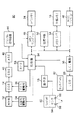
また、ディジタル信号処理部44は、撮像された画像データの画像サイズを液晶表示パネル26における表示サイズに変換する機能を有する。たとえば、ディジタル信号処理部44は、連写モードが設定されている場合に、Δt 間隔で撮影された複数の画像データが表す画像を縦横に配列して、たとえば9コマ分の縮小画像を液晶表示パネル26に表示させるための表示データを作成する。ディジタル信号処理部44は、連写モードが「前/後」である場合にタイミングt=-4Δt,-3Δt,・・・ 3Δt, 4Δt の各撮像タイミングにてメインメモリ24に格納された各コマの画像データを処理して、各タイミングにて撮像された画像のマルチ画面を作成する。こうして、たとえば、図1に示すように、液晶表示パネル26には、t=-4Δt 〜t= 4Δt の各撮像タイミングにて連続写真撮影されたコマの画像が表示される。
【0019】
なお、連写モードが「前」であるときにはディジタル信号処理部44は、タイミングt=-8Δt,-7Δt,・・・ -Δt,0 の各撮像タイミングにて格納された各コマの画像データを処理して、これら各コマのマルチ画面を表す表示データを作成する。同様にディジタル信号処理部44は、連写モードが「後」であるときには、タイミングt=0, -Δt,・・・ 7Δt, 8Δt の各撮像タイミングにて得られた画像データを処理してマルチ画面を表す表示データを作成する。
【0020】
ディジタル信号処理部44は、このように表示されるマルチ画面内のコマを選択する制御信号を制御部38より入力すると、各画像コマの枠の色および輝度を変化させて、変化した枠内の画像が選択可能であることを他のコマの画像とは区別して示す。
【0021】
また、ディジタル信号処理部44は、ADC 42から出力される画像データに基づいて、ピント調整および明るさ調整等の撮像制御を行うための各種評価値を算出する機能を有する。ディジタル信号処理部44は、撮像画面を64分割し、分割された各ブロックごとの画像データからそれぞれ評価値を算出する。たとえば、信号処理部44は、画像データの各ブロックレベルを積算により算出し、その積算結果と測光モードとに応じて、被写界の測光値を算出する機能を有し、算出した測光値を制御部38に通知する。制御部38は、この測光データに基づいて、光学系ブロック12における絞り値およびシャッタ開放時間を規定する制御信号を生成して光学系駆動部34に供給するとともに、撮像素子14に対する電子シャッタ速度を規定する制御信号をCCD 駆動部36に供給する自動露出調整機能を有する。
【0022】
さらに、ディジタル信号処理部44は、撮像レンズの焦点位置を移動させて撮像されたブロックごとの画像データから被写界のコントラスト成分を抽出してコントラスト評価値を算出し、最大のコントラスト評価値が得られた位置に撮像レンズを制御する制御信号を生成する自動焦点調節機能を有する。さらに、信号処理部44は、制御部38から指定されるオートホワイトバランス(AWB) モードに応じて、被写界における光源の状態、つまり色温度を判断し、その判断結果に従って画像データの各RGB 信号の色バランスを調整する自動ホワイトバランス調整機能を有する。
【0023】
ディジタル信号処理部44に接続されたメモリコントローラ46は、信号処理部44との画像データの受け渡しを行って、メインメモリ24に対するデータ書込みおよび読出しを制御する記憶制御機能を有する。また、メモリコントローラ46は、制御部38からの制御信号に応動して、バス50に接続された各部とのデータ転送を制御する。本実施例におけるメインメモリ24は、撮像された9コマ分の画像データを格納する記憶領域を有し、コントローラ46から供給されるアドレスおよび書込制御信号に応じて画像データを格納する。
【0024】
連写モードにて、モード切替ダイヤル20が「前」および「前/後」に設定されている場合に、メモリコントローラ46は、制御部38からの制御信号に従って、Δt 期間ごとにそれぞれ撮像される画像データを順次9コマ分メインメモリ24に書込み、その後の画像データに対しては、格納された画像データのうち、書き込まれた時刻が最も古い画像データを消去して、その消去後の空き領域に、撮像タイミングにて得られる最新の画像データを巡回的に書き込んでゆく。
【0025】
ここでモード切替ダイヤル20が「前」であるときには、レリーズ釦22の全押しに応動する制御部38からの制御信号に従って、メインメモリ24に格納された最近の9コマ画像をディジタル信号処理部44に読み出し、信号処理部44にて処理されたこれら画像データによるマルチ表示用の表示データをバス50に転送する。また、モード切替ダイヤル20が「前/後」に設定されている場合、メモリコントローラ46は、順次最新の画像データを書き込んでいる際に、レリーズ釦22の全押しに応動する制御部38からの制御信号を受けると、さらに以降の、9コマ未満の複数コマ、たとえば、レリーズタイミング直後の1コマを含む5コマの最新画像データを、メインメモリ24における最古の画像データを削除しながらメインメモリ24に格納する。
【0026】
なお、連写モードにてモード切替ダイヤル20が「後」に設定されている場合にメモリコントローラ46は、レリーズ釦22の全押しに応動して生成される制御部38からの制御信号に従って、期間Δtごとにそれぞれ撮像される画像データを順次9コマ分メインメモリ24に書込むことにより、レリーズ操作後の複数コマを格納させる。
【0027】
メモリコントローラ46は、このようにしてメインメモリ24に格納した最近の複数コマの画像データを読み出してディジタル信号処理部44に入力し、信号処理部44にて処理されたこれら画像データによるマルチ表示用の表示データをバス50に転送する。なお、連写モードではなく通常の1コマ撮影モードが設定されている場合に、メモリコントローラ46は、レリーズ釦22の全押し状態にて撮像された画像データを、モード切替ダイヤル20の設定位置に関係なく、メインメモリ24に格納する。
【0028】
バス50に接続された圧縮/伸張回路52は、ディジタル信号処理部44にてYC変換された画像データを圧縮符号化する回路であり、本実施例では、YCデータを縦横8画素ごとのブロックに分割し、2次元直交変換および量子化し、さらにハフマン符号化するJPEG方式が適用されている。圧縮/伸張回路52は、符号化した画像データをバス50を介してメモリインタフェース(I/F) 回路54に転送し、メモリインタフェース回路54は、着脱可能に接続される外部メモリ16とバス50側との電気的な整合をとって、外部メモリ16に対する画像データの書込みおよび読出しを制御する回路である。たとえば、メモリインタフェース回路54は、外部メモリ16を駆動する駆動回路を含み、外部メモリ16がEEPROMやフラッシュメモリ等の半導体記憶回路である場合に、所定の書込および読出コマンドを生成して、外部メモリ16に対する記憶制御を行う。
【0029】
バス50に接続され、外部メモリ16を着脱可能に接続するメモリインタフェース(I/F) 回路54は、圧縮伸張回路52にて処理された画像データを外部メモリ16の所定の記憶領域に書込み、また、外部メモリ16に記憶された画像データを読み出して圧縮伸張回路52に転送する記憶制御回路である。この外部メモリ16は、本実施例では、EEPROMやフラッシュメモリ等の半導体メモリをカード状の筐体に収容したメモリカードが適用されるが、これに限らず、たとえば、光磁気ディスクなどの回転記録媒体や光カードなど他の記録形式の情報記録媒体を使用してもよい。なお、外部メモリ16の記憶容量がメインメモリ24から選択される画像データのデータ量に比べて充分に大きい場合には、メモリインタフェース回路54は、非圧縮の選択画像データを、ディジタル信号処理回路44またはメインメモリ24から入力して、外部メモリ16に記録してもよい。
【0030】
バス50にはさらに、LCD 駆動回路56とNTSCエンコーダ48とがそれぞれ接続され、LCD 駆動回路56は、液晶表示パネル(LCD) 26を駆動するとともに、メインメモリ24から読み出され、ディジタル信号処理部44にて処理された表示データを液晶表示パネル26に供給して、表示データに応じた静止画像および動画像を表示させる回路である。LCD 駆動回路56の出力に接続される液晶表示パネル26は、本実施例では図1に示したように本カメラ10の背面側に、主として光学ファインダ60を覗く方向から被写界の画像確認が行えるように配設されている。この液晶表示パネル26は、2枚の透明板の間にRGB カラーフィルタ、偏光板および液晶が配置され、入力される画像データに応じて、可視画像を形成する液晶ディスプレイである。もちろん、液晶表示パネル26に代えて他の表示装置、たとえば、EL (Electro Luminescence) やPDP (Plasma Display Panel)等の表示装置を備えてもよい。また、液晶表示パネル26を駆動するLCD 駆動回路56等の周辺回路機能を液晶表示パネル26の基板上に形成してもよい。NTSCエンコーダ48は、バス50を介して入力される画像データを、外部接続されるモニタ装置の信号入力形式に変換する変換回路であり、本実施例ではRGB 画像データをNTSC形式の画像信号に変換して出力する。
【0031】
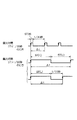
制御部38は、操作部18への操作状態に応動して各部を制御する回路であり、制御プログラムを実行演算する中央処理装置、ROM,RAM 等の記憶回路および周辺回路を含む。制御部38は、とくに連写モードが設定されている場合に、モード切替ダイヤル20の状態に応じた撮像制御および記録制御を行う。詳しくは、制御部38は、連写モードでは撮影間隔Δtを決定する。たとえば、図3に示すように、制御部38は、ディジタル信号処理部44にて算出される測光値から撮影時の露出値を決定する。制御部38は、決定した露出値およびAEモードに応じてシャッタ速度STを決定し、シャッタ速度STが1/30秒以下の場合には、シャッタ速度STに対応する露出期間STに、1コマの画素信号転送時間の1/30秒を加えた時間を撮影間隔Δtに設定する。また、シャッタ速度STが1/30秒を超える長い時間の場合では、制御部38は、その露出期間STを2倍した期間を撮影間隔Δtに設定する。この場合、上述したように露出期間STに1/30秒を加えた期間を撮影間隔Δtに設定してもよい。
【0032】
制御部38に接続されるタイマ回路58は、制御部38からの制御信号に応動して、制御部38にて設定された撮影間隔Δtを計時し、期間Δtを規定するタイミング信号を生成する。タイマ回路58は、このタイミング信号をΔt期間ごとの割込信号として制御部38に供給する。制御部38は、この割込信号を割込受付有効期間内にて検出するたびに割込みを許可し1コマの撮影を行うための制御信号を光学系駆動部34およびCCD 駆動部36に出力する。
【0033】
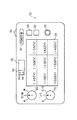
制御部38は、操作部18にて検出される操作情報を認識して、操作に応じた制御を行う。操作部18は、電源スイッチ62と、上述した半押し、全押し操作を検出するためのレリーズ釦およびレリーズスイッチを有し、レリーズスイッチは半押しを検出するレリーズスイッチS1と全押しを検出するレリーズスイッチS2とを含む。連写モード切替ダイヤル20は、「前」、「前後」および「後」の設定位置に応じた設定情報を出力する切換スイッチである。この設定情報を認識する制御部38は、とくに「前/後」設定では、レリーズスイッチS2オン直後のt=0 からの画像を5コマ、さらに撮像し、メインメモリ24に格納するように制御する。しかし、これに限らず、制御部38は、スイッチS2オン直後から設定位置に応じた2〜8コマの静止画像をΔt間隔で撮像するように制御し、前後の撮像バランスを変更することができる。また、このような設定を1コマまたは9コマとすることにより、「前」設定または「後」設定と同等の動作を行ってもよい。
【0034】
さらに、操作部18には、メインメモリ24に格納されて液晶モニタ26に表示される画像を選択するための前選択スイッチ28、後選択スイッチ30および決定/保存スイッチ32が備えられ、これらスイッチへの操作状態に応じて制御部38は、各撮影タイミングにて撮像されてモニタ表示されている画像の中から所望の画像を選択し、選択した画像を外部メモリ16に保存させる。前選択スイッチ28および後選択スイッチ30により選択されるコマの画像枠には上述の通り、枠の色や輝度などの属性が変更されて選択されていないコマの画像とは区別され、そのコマの画像を決定/保存スイッチ32がオンされることにより外部メモリ16へ記録する制御が行われる。
【0035】
さらに、制御部38は、撮像素子14から出力される画素信号に基づいて、焦点調節、絞り値およびシャッタ速度決定処理等の撮像調整処理を行う機能を有する。たとえば、ディジタル信号処理部44では、ADC 42にて変換された画像データから、撮像調整を行うための各種評価値を算出し、制御部38は、それら評価値に応じて各部を制御する。具体的には制御部38は、算出された評価値に基づいて、撮像レンズの焦点位置を制御する制御信号と、メカニカルシャッタの開放時間を制御する制御信号とを光学系駆動部34に出力する。また、制御部38は、算出された評価値に基づいて、撮像素子14における電荷蓄積期間を制御する電子シャッタ制御信号をCCD 駆動部36に出力する。さらに制御部38は、算出された評価値に基づいて、画像データの色バランスを制御する制御信号をディジタル信号処理部44に出力する。ディジタル信号処理部44では、RGB 各画像データのレベルを色バランスの制御信号に応じて調整しホワイトバランス調整を行う。
【0036】
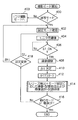
以上のような構成で本実施例におけるディジタルカメラ10の動作を図4〜図9を参照して説明する。動作モード設定により撮影モードが設定されていると、図4のステップ400 において、連写モードが設定されているか否かが制御部38にて判定されて、連写モードである場合にはステップ402 に進み、連写モードではない場合にはステップ403 に進んで1コマ撮影モードへ移行する。ステップ402 では、モード切替ダイヤル20による現在の設定が「前」、「前/後」および「後」のいずれの設定であるかが制御部38にて確認される。
【0037】
続くステップ404 に進むと、光学系ブロック12および撮像素子14が駆動されてモニタ用の撮像が開始される。このときメカニカルシャッタは開放状態に制御され、撮像レンズにより撮像素子14の撮像面に結像される被写界像に応じた画素信号が撮像素子14より出力される。撮像素子14の出力は、CDS 40, ADC 42にて処理され、処理された画像データはディジタル信号処理部44に入力される。
【0038】
ディジタル信号処理部44では、連続して表示する動画像のための簡易的な画像処理を行って、処理された画像データをメモリコントローラ46およびバス50を介してLCD 駆動回路56に供給する。こうして液晶表示パネル26には、光学ファインダ60における視野と同様に被写界の状態が映し出され、被写体の様子などを確認することができる。また、このモニタ用映像の表示処理を行う際、ディジタル信号処理部44および制御部38は、撮像された画像データに基づいて、撮像素子14に対する電子シャッタ制御や絞り値を設定して動画像表示のための輝度調整を行う。また、このとき、撮像画像データに応じた評価値に基づいて焦点調節を自動的に行ってもよい。
【0039】
このようなモニタ表示状態にて、ステップ406 では、レリーズ釦が半押し状態となったか否かが判定される。ここでレリーズスイッチS1のオン状態が検出されると、ステップ408 に進み、ステップ408 では、静止画撮影のための自動露出調整、自動焦点調節および自動ホワイトバランス調整などの撮像調整処理が行われる。この撮像調整では、動画像のモニタ表示の際よりも精度の高い調節が行われる。なお、以降のステップ414 におけるレリーズスイッチS2のオン状態が検出される前に、スイッチS1が一旦オフ状態に復帰した場合には、ステップ404 および406 における処理が再実行される。
【0040】
ステップ408 における調整が完了するとステップ410 に進み、決定されたシャッタ速度(露出時間)STに応じて、撮影タイミングの間隔Δtが決定される。このとき、ステップ408 にて求められた測光値から算出されたシャッタ速度STが、1/30秒以下であった場合には、シャッタ速度STに1/30秒を加えた時間が期間Δtに設定され、逆に、シャッタ速度STが1/30秒を超える値であるときには、シャッタ速度STに値2を乗算した値がΔtに設定される。制御部38は、このようにして決定した撮影タイミングΔtをタイマ58に設定し、続くステップ412 にてこれに応動して計時が開始され、期間Δtごとのタイミング信号がタイマ58にて生成される。
【0041】
次いでステップ414 に進むと、このステップ414 では、レリーズスイッチS2の検出およびモード設定に応じた処理、さらには、画像選択および選択画像の記録処理が行われる。
【0042】
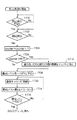
詳しくは、モード切替ダイヤルが「前」にセットされている場合、図5に示すステップ500 に進み、制御部38は、タイマ58から出力されるタイミング信号の割込受付を有効化して割込みがあった場合にそれを許可する。続くステップ502 における割込処理aでは、図6に示すステップ600 にて記憶カウンタ(counter) が初期値0にセットされて、続くステップ602 では、割込受付が有効であるか否かが判定される。ここで有効である場合にはステップ604 に進んで、タイマ58からのタイミング信号が割込信号として検出されたか否かが判定される。タイミング信号が検出されると、制御部38は、ステップ606 に進み、撮像制御を開始するとともに、続くステップ608 にて、カウンタ値に値1を加算する(counter=counter+1 )。
【0043】
次いでステップ610 に進み、カウンタ値が値9を超えているか否かが判定され、カウンタ値が値9以下である場合には、ステップ612 に進んで、撮像制御により被写界が撮像される。生成された画像データはメインメモリ24に格納される。また、ステップ610 にて、カウンタ値が値9を超えていると判定された場合にはステップ614 に進み、メインメモリ24に格納されている画像データのうち、最古の画像データがメインメモリ24から消去され、その後ステップ612 における撮像および画像データの格納処理が行われる。
【0044】
画像データが格納されると、ステップ616 に進み、レリーズスイッチS2がオンされたか否かが判定され、そのオン状態が検出されると図5に示した次のステップ504 に進む。また、レリーズスイッチS2のオン状態がまだ検出されなかった場合には、ステップ602 に戻って、以降の処理が繰り返される。このようにして、レリーズスイッチS2のオン状態が検出されるまで、撮像制御により得られた最近9コマ分の画像データがメインメモリ24に格納され、このとき撮像時刻の古い画像データから順に削除されて、メインメモリ24に格納されている画像データが巡回的に更新される。なお、ステップ616 にてレリーズスイッチS2のオン状態が検出された後は、あと1コマの撮像およびメインメモリ24への格納処理を行ってから図5に示したステップ504 に進むことにより、この「前」設定ではレリーズS2を検出した直後の1コマの撮像画像をt=0 におけるコマとする。
【0045】
こうして割込処理aが完了すると、図5に示すステップ504 に進み、割込受付が無効化され、タイミング信号に応じた撮像制御が停止され、メインメモリ24への画像データの更新処理も終了する。
【0046】
次いでステップ506 に進み、メインメモリ24に格納されたタイミングt=-8〜0 までの画像データが順に読み出され、これら画像データはディジタル信号処理部44にて表示データに変換された後、バス50を介してLCD 駆動部56に供給される。こうして、液晶表示パネル26には、各撮像タイミングにて撮像された最近9コマの撮像画像がマルチ画面上に表示される。
【0047】
ここでステップ508 に進み、表示された各コマの画像を選択するために操作部18の前選択スイッチ28および後選択スイッチ30への操作状態が検出されると、マルチ画面における表示枠の色および輝度が変更されて、操作者に対し選択可能であることが示され、そこで決定/保存スイッチ32がオン状態に制御されるとステップ510 に進む。このとき、操作に応じて複数コマを選択することができる。決定/保存スイッチ32への操作が検出されると、操作者が選択および決定したコマの画像データがメインメモリ24から読み出されて、バス50に転送され、選択された画像データは圧縮伸張部52にて圧縮符号化処理を受け、処理された画像データは、メモリインタフェース回路54に供給される。このとき制御部38は、画像データの撮影時刻等の各種管理情報をメモリインタフェース回路54に供給し、メモリインタフェース回路54はこれら情報と画像データとを外部メモリ16の所定の記憶領域に記録する。
【0048】
所望の画像データが外部メモリ16に記録されると、図4に示したステップ416 に進み、他の動作モードに変更されたか否かおよび電源スイッチ62がオフ状態に操作されたか否かが判定されて、このような操作状態が検出された場合には操作に応じた処理が行われる。また、このような変更操作が検出されなかった場合には、ステップ418 に進み、モード切替ダイヤル20の設定位置が変更されたか否かが判定され、変更ありの場合にはステップ402 に戻り、変更なしの場合にはステップ404 に戻って、それぞれ以降の処理が続けられる。
【0049】
以上のようにしてモード切替ダイヤル20が「前」の設定位置にある場合には、レリーズスイッチS1に応動して最近9コマの画像データがメインメモリ24に格納され、スイッチS2がオン状態に操作されると、さらに1コマの撮像を行って、レリーズスイッチS2オン直後の撮像画像を含む画像データがメインメモリ24に格納される。したがって、メインメモリ24に格納された画像データの中から、所望の撮像タイミングにて撮像された画像データを選択して出力することができる。
【0050】
次に、モード切替ダイヤルが「前/後」に設定されていた場合のステップ414 (図4)における処理について説明する。この処理は、レリーズスイッチS2のオン状態を検出した後、さらに複数コマの撮像を各撮像タイミングにて行う点で、モード切替ダイヤルが「前」の場合と異なり、その他の動作については同様である。詳しくは、図7に示すステップ700 およびステップ702 において、図5および図6に示したステップ500 およびステップ502 における割込受付有効化処理と割込処理aと同様の処理が行われる。ステップ702 における割込処理aにおいて、レリーズスイッチS2のオン状態が検出されると、ステップ704 に進みレジスタiが初期値0 (i=0)にセットされて、ステップ706 における割込処理bに移行する。
【0051】
この割込処理bは、図8に示すように、図6で示した割込処理aのステップ600 およびステップ616 における処理を行わない点で異なり、ステップ800 〜ステップ812 における各処理によって、Δtごとの撮像処理および最古画像のメインメモリ24からの消去処理を行って、最新画像1コマの更新処理が行われる。ステップ812 にて画像データの格納が完了すると、図7に示したステップ708 に進み、レジスタiに値1が加算され (i=i+1)、続くステップ710 では、レジスタiの保持値が5と等しくなっているか否かが判定される。ここで、等しくない場合には、ステップ706 における割込処理b以降の処理がレジスタ値が値5となるまで繰り返される。こうして、レリーズスイッチS1オン後からスイッチS2オンまでの4コマの画像がメインメモリ24に格納され、スイッチS2オン後から5コマまで撮像された画像データがメインメモリ24に格納された状態となる。
【0052】
レジスタiの保持値が値5となるとステップ712 に進んで、割込受付が無効化されて、撮像処理およびメインメモリ24に対する画像データの格納処理が終了する。続くステップ714 では、メインメモリ24に格納されたタイミングt=-4〜+4の画像データが読み出され、画像データはディジタル信号処理部44にて処理された後LCD 駆動部56に供給される。こうして、液晶表示パネル26には、各撮像タイミングにて撮像されたレリーズスイッチS2がオンされる前の4コマの画像と、オン直後からの5コマの撮像画像がマルチ画面上に表示される。
【0053】
ステップ716 において、この画像表示に応じて所望のコマの画像が選択および決定されると、ステップ718 に進み、操作者が選択および決定したコマの画像データがメインメモリ24から読み出されて、圧縮符号化処理され、処理された画像データがメモリインタフェース回路54を介して外部メモリ16に記録される。その後、図4に示したステップ416 に進み、他の動作モードおよび電源スイッチ62がオフ状態に操作されたか否かが判定されて、このような操作状態が検出された場合には操作に応じた処理が行われる。また、このような変更操作が検出されなかった場合には、ステップ418 に進み、モード切替ダイヤル20の設定位置が変更されたか否かが判定され、変更ありの場合にはステップ402 に戻り、変更なしの場合にはステップ404 に戻って、それぞれ以降の処理が続けられる。
【0054】
このようにして、モード切替ダイヤルが「前/後」の設定位置にある場合には、レリーズスイッチS1に応動して最近9コマの画像データがメインメモリ24に更新的に格納され、スイッチS2がオン状態に操作されると、さらに5コマの撮像が行われ、レリーズスイッチS2オン前の4コマの画像と、オン直後からの5コマの撮像画像とを含む複数の画像データがメインメモリ24に格納された状態となる。したがって、メインメモリ24に格納された画像データの中から、所望の撮像タイミングにて撮像された画像データを選択することができる。
【0055】
次に、モード切替ダイヤルが「後」に設定されていた場合のステップ414 (図4)における処理について説明する。この設定では、図9に示すステップ900 において、レリーズスイッチS2がオンされたか否かが判定され、スイッチS2のオン状態が判定されるとステップ902 にて割込受付が有効化される。次いでステップ904 に進むと、レジスタiの値が値0に初期化されて、ステップ906 では割込みが検出されたか否かが判定される。
【0056】
ここで割込みが検出されると、ステップ908 にて撮像制御が行われ、タイミング信号に応動して撮像され処理された1コマの画像データがメインメモリ24に格納される。続くステップ910 ではレジスタの保持値に値1が加算され (i=i+1)、ステップ912 では、レジスタiの保持値が値9と等しいか否かが判定される。等しい場合には、ステップ914 にて割込受付が無効化され、等しくない場合にはステップ906 に戻って割込みの検出待ちとなる。
【0057】
このようにしてレジスタiの保持値が値9となるまでの回数分だけ、タイミング信号によるΔt間隔にて撮像およびメインメモリ24への画像データの格納が行われると、ステップ916 では、メインメモリ24に格納されている9コマ分の画像データが読み出されて、これら画像データに応じた表示画像が液晶表示パネル26にマルチ表示される。ここで、操作者による選択操作が行われたことがステップ918 にて判定されると、ステップ920 にて、選択画像データが外部メモリ16に記録され、この記録処理が完了すると図4に示したステップ416 に進んで以降の処理が行われる。
【0058】
このように、モード切替ダイヤルが「後」の設定位置にある場合には、レリーズスイッチS2に応動して9コマの画像データがメインメモリ24に格納される。したがって、メインメモリ24に格納された画像データの中から、所望の撮像タイミングにて撮像された画像データを選択することができる。
【0059】
以上説明した実施例では、連写される複数コマの画像をメインメモリ24に格納して、格納された画像データの中から所望の画像を選択するように構成されていた。しかしこれに限らず、たとえば、連写モードにて撮像されて生成および処理された画像データを外部メモリ16に記録し、この連写モードにて複数のコマが記録された外部メモリ16から連写による複数画像を読み出して再生し、再生表示された複数コマの画像から所望の画像を選択して、選択しなかった非選択コマの画像を外部メモリ16から消去することにより、選択画像を外部メモリ16に残すようにしてもよい。
【0060】
この場合、制御部38は、ディジタル信号処理部44にて処理された画像データを圧縮伸張部52にて圧縮符号化させ、符号化された画像データをメモリインタフェース回路54に供給させて間隔Δtごとの撮影された複数コマの画像データを外部メモリ16に記録させる。外部メモリ16に残すコマを選択させる際、制御部38は、連写モードにて複数記録された画像データを読み出す制御信号をメモリインタフェース回路54に供給し、読み出される画像データを圧縮伸張部52にて復号させ、処理された画像データを一旦メインメモリ24に格納させる。さらに制御部38は、これら格納された画像データを信号処理部44にて表示データに変換させて、変換された表示データをLCD 駆動回路56に転送させることにより、複数コマのマルチ画像を液晶表示パネル26に表示させる。制御部38は、操作部18にて検出される操作状態を認識し、外部メモリ16に残す画像を選択する操作に応じて、選択された以外のコマの画像を外部メモリ16から消去させる制御信号をメモリインタフェース回路54に供給する。
【0061】
このように構成した場合の動作を、モード切替ダイヤルが「前/後」に設定されている場合について図10を参照して説明する。カメラ10全体の動作は、図4に示す全体フローと同様の動作でよく、そのステップ414 における処理では、図10に示すように、ステップ1000において、タイマ58から出力されるタイミング信号の割込受付が有効化される。
【0062】
続くステップ1002における割込処理aでは、図11に示すステップ1100にて記憶カウンタ(counter) が初期値0にセットされて、続くステップ1102では、割込受付が有効であるか否かが判定される。ここで有効である場合にはステップ1104に進んで、タイマ58からのタイミング信号が割込信号として検出されたか否かが判定される。タイミング信号が検出されると、制御部38は、ステップ1106に進み、撮像制御を開始するとともに、続くステップ1108にて、カウンタ値に値1を加算する(counter=counter+1 )。次いでステップ1110に進み、カウンタ値が値9を超えているか否かが判定される。
【0063】
カウンタ値が値9以下である場合には、ステップ1112に進んで、撮像制御により生成された画像データが外部メモリ16に格納される。また、ステップ1110にて、カウンタ値が値9を超えていると判定された場合にはステップ1114に進み、外部メモリ16に格納されている画像データのうち、最古の画像データが外部メモリ16から消去され、その後ステップ1112における画像データの記録処理が行われる。
【0064】
画像データが外部メモリ16に格納されると、ステップ1116に進み、レリーズスイッチS2がオンされたか否かが判定され、そのオン状態が検出されると図10に示したステップ1004に進む。また、レリーズスイッチS2のオン状態がまだ検出されなかった場合には、ステップ1102に戻って、以降の処理が繰り返される。このようにして、レリーズスイッチS2のオン状態が検出されるまで、撮像制御により得られた最近9コマ分の画像データが外部メモリ16に記録され、このとき撮像時刻の古い画像データから順に削除されて、外部メモリ16に記録されている画像データが巡回的に更新される。なお、ステップ1116にてレリーズスイッチS2のオン状態が検出された後は、あと1コマの撮像およびメインメモリ24への格納処理を行ってから図10に示したステップ1004以降の処理を行うことにより、この「前」設定ではレリーズS2のオン状態を検出した後のタイミングにて撮像される1コマの撮像画像をt=0 におけるコマとする。
【0065】
こうして割込処理aが完了すると、図10に示すステップ1004に進み、レジスタiが初期値0 (i=0)にセットされて、ステップ1006における割込処理bに移行する。
【0066】
この割込処理bは、図12に示すように、図11で示した割込処理aのステップ1100およびステップ1116における処理を行わない点で異なり、ステップ1200〜ステップ1210における各処理によって、Δtごとの撮像処理および最古画像の外部メモリ16からの消去処理を行って、最新画像1コマの更新処理が行われる。ステップ1210にて画像データの格納が完了すると、図10に示したステップ1008に進み、レジスタiに値1が加算され (i=i+1)、続くステップ1010では、レジスタiの保持値が値5と等しくなっているか否かが判定される。ここで、等しくない場合には、ステップ1006における割込処理b以降の処理がレジスタ値が値5となるまで繰り返される。こうして、レリーズスイッチS1オン後からスイッチS2オンまでの4コマの画像が外部メモリ16に記録され、スイッチS2オン後から5コマまで撮像された画像データが外部メモリ16に記録された状態となる。
【0067】
レジスタiの保持値が値5となるとステップ1012に進んで、割込受付が無効化されて、撮像処理および外部メモリ16に対する画像データの格納処理が終了する。続くステップ1014では、外部メモリ16に格納されたタイミングt=-4〜+4までの画像データがメインメモリ24に読み出され、画像データはディジタル信号処理部44にて処理された後LCD 駆動部56に供給される。こうして、液晶表示パネル26には、各撮像タイミングにて撮像されたレリーズスイッチS2がオンされる前の4コマの画像と、オン直後からの5コマの撮像画像がマルチ画面上に表示される(ステップ1016)。
【0068】
ステップ1018において、この画像表示に応じて所望のコマの画像が選択および決定されると、操作者が選択および決定したコマを除くコマの画像、つまり非選択の画像が外部メモリ16から消去される。その後、図4に示したステップ416 に進み、他の動作モードおよび電源スイッチ62がオフ状態に操作されたか否かが判定されて、このような操作状態が検出された場合には操作に応じた処理が行われる。また、このような変更操作が検出されなかった場合には、ステップ418 に進み、モード切替ダイヤルの設定位置が変更されたか否かが判定され、変更ありの場合にはステップ402 に戻り、変更なしの場合にはステップ404 に戻って、それぞれ以降の処理が続けられる。
【0069】
このように本実施例では、複数の撮像タイミングにて得られた複数コマの画像データを外部メモリ16に記録し、操作者により選択した画像を除くコマ、つまり不要なコマの画像を外部メモリ16から削除することにより、所望する画像データを外部メモリ16に残すことができる。なお、上記説明は、モード切替ダイヤル20が「前/後」の設定位置にある場合について説明したが、「前」および「後」にセットされている場合についても、有効に適用することができる。
【0070】
なお、各実施例では、レリーズ釦22の半押し状態をレリーズスイッチS1で検出し、これに応じた動作制御を行っているが、このような手操作に代えて、たとえば、操作者による撮影準備動作を検出して、その検出結果をレリーズスイッチS1のオン状態と見なしてもよい。
【0071】
たとえば、図1および図2に示す光学ファインダ60に近接する左方に、カメラ10を目の位置に構えて光学ファインダ60を覗く際に、近距離に位置される操作者の目や皮膚を検出するセンサ64を設ける。このセンサ64は、LED 等の発光素子66と受光素子68とを含み、たとえば、発光素子66は赤外光を周期的に発光させ、受光素子68は至近距離からの赤外反射光を検出して、反射光に応じた検出信号を出力する。センサ60の出力は、操作部18に接続され、本実施例における操作部18はこの検出信号を制御部38に通知すると、制御部38は、この検出信号をレリーズスイッチS1がオンされた状態であると認識する。このような機能は、たとえば、撮像時における液晶モニタ表示をオフ状態にして省エネ駆動させ、光学ファインダ60を使用する場合などに有効である。
【0072】
次に図13および図14を参照して、ディジタルカメラの他の実施例を説明する。同図に示すディジタルカメラ70は、図1および図2に示したカメラ10における機能構成に加えて、とくに連写モードにて、露出値を所定段階ごとに補正しながら撮像する自動段階露出(オートブラケッティング)を行う機能をさらに備えている。なお、以下の説明において、図1および図2に示した構成と同じ構成については同一の参照符号を付し、その説明を省略する。
【0073】
ディジタルカメラ70は、図13に示すように、自動段階露出を行う場合に、その露出変更幅を設定する露出段階設定ダイヤル72(以下、ABE ダイヤル72と称する)を操作部18に備え、ABE ダイヤル72は、オートブラケッティングを行わない0位置、1/3 EV段階のブラケッティング撮影を行う1/3 位置および2/3 EV段階のブラケッティング撮影を行う2/3 位置の各設定位置を有する。図14に示す制御部74は、図1および図2に示した機能構成に加えて、オートブラケッティングを行うための撮像制御を行う機能を有する。なお、ブラケッティング機能における露出段階は 1/3段階に限らず、他のステップ、たとえば 1/2段階を使用してもよく、またこれら段階を併用してもよい。
【0074】
詳しくは制御部74は、連写モードにて、ABE ダイヤル72が、1/3 または 2/3位置にセットされると、レリーズ釦22への操作に応動して、設定段階に応じたΔEV間隔のプラス補正およびマイナス補正による撮像制御を行い、さらに、連写モードに応じた複数コマの撮像を行う。このとき制御部74は、絞り値またはシャッタ速度を制御して露出変更を行う。とくに、シャッタ速度STを変更して露出時間が長くなる場合には、上述の実施例と同様にして、露出時間STが1/30秒を超える際に、決定されるシャッタ速度STを2倍した撮像間隔Δtにて、撮像するように光学系駆動部34およびCCD 駆動部36を制御する。逆に露出時間STが1/30秒以下の際に、決定される露出時間STに1/30秒を加えた期間を撮像間隔Δtに設定する。タイマ58は、制御部74により設定される期間Δt間隔のタイミング信号を制御部74に供給する。制御部74は、割込受付有効期間にてこのタイミング信号を入力すると、その割込みを受け付け、撮像制御や画像データの処理および転送等の制御を行う。
【0075】
以上のような構成で、本実施例におけるディジタルカメラ70の動作を図15〜図17を参照して説明する。以下の説明では、モード切替ダイヤル20が「前/後」に設定されている場合について説明する。本カメラ70の基本動作は、図4に示した動作フローと同様の動作でよく、そのステップ414 における動作では、図15に示すように、ステップ1500において、制御部74は、タイマ58から出力されるタイミング信号の割込受付を有効化する。
【0076】
続くステップ1502における割込処理aでは、図16に示すステップ1600にて記憶カウンタ(counter) が初期値0にセットされて、続くステップ1602では、割込受付が有効であるか否かが判定される。ここで有効である場合にはステップ1604に進んで、タイマ58からのタイミング信号が割込信号として検出されたか否かが判定される。タイミング信号が検出されると、制御部74は、ステップ1606に進み、撮像制御を開始するとともに、続くステップ1608にて、カウンタの保持値に値1を加算する(counter=counter+1 )。
【0077】
次いでステップ1610に進み、カウンタ値が値81を超えているか否かが判定され、カウンタ値が値81以下である場合には、ステップ1612に進んで、撮像制御により撮像され、生成された画像データがメインメモリ24に格納される。また、ステップ1610にて、カウンタ値が値81を超えていると判定された場合にはステップ1614に進み、メインメモリ24に格納されている画像データのうち、最古の画像データから数えて9番目までの9コマの画像データがメインメモリ24から消去される。次いでステップ1612に進むと、露出レベルΔEVが、測光データに応じた適正露出値よりも4段階分マイナス補正するように、露出レベルレジスタの保持値が-4ΔEVにセットされる。
【0078】
ステップ1616に進むと、セットされた-4ΔEVにて撮像が行われて、処理された画像データはメインメモリ24に格納される。続くステップ1618では、露出レベルレジスタの保持値にΔEV分の値を加算した値がセットされる。次いでステップ1620に進むと、露出レベルレジスタの保持値が+4ΔEVを超えたか否かが判定されて、超えている場合にはステップ1622に進み、逆に、超えていない場合にはステップ1616に戻って、以降、現在の保持値に応じた露出値にて、タイミング信号に応動した撮像および画像データの格納処理が行われる。
【0079】
ステップ1622に進むと、レリーズスイッチS2がオンされたか否かが判定され、そのオン状態が検出されると図15に示した次のステップ1504に進む。また、レリーズスイッチS2のオン状態がまだ検出されなかった場合には、ステップ1602に戻って、以降の処理が繰り返される。このようにして、レリーズスイッチS2のオン状態が検出されるまで、撮像制御により得られた最近81コマ分の画像データがメインメモリ24に格納され、このとき撮像時刻の古い画像データから順に削除されて、メインメモリ24に格納されている画像データが巡回的に更新される。
【0080】
こうして割込処理aが完了すると、図15に示すステップ1504に進み、レジスタiが初期値0 (i=0)にセットされて、ステップ1506における割込処理bに移行する。
【0081】
この割込処理bは、図17に示すように、図16で示した割込処理aのステップ1600およびステップ1622における処理を行わない点で異なり、ステップ1700〜ステップ1716における各処理によって、Δtごとの撮像処理および最古画像9コマのメインメモリ24からの消去処理を行って、露出を変更して撮像した最近画像9コマの更新処理が行われる。
【0082】
ステップ1716にて、露出レベルレジスタの保持値が+4ΔEVを超えていると判定されると、図15に示したステップ1508に進み、レジスタiに値1が加算され (i=i+1)、続くステップ1510では、レジスタiの保持値が値5と等しくなっているか否かが判定される。ここで、等しくない場合には、ステップ1506における割込処理b以降の処理がレジスタ値が値5となるまで繰り返される。こうして、レリーズスイッチS1オン後からスイッチS2オンまでの4コマ×9段階の36コマの画像がメインメモリ24に格納され、スイッチS2オン後から撮像された5コマ×9段階の45コマの画像データがメインメモリ24に格納された状態となる。
【0083】
レジスタiの保持値が値5となるとステップ1512に進んで、割込受付が無効化されて、撮像処理およびメインメモリ24に対する画像データの格納処理が終了する。続くステップ1514では、メインメモリ24に格納されたタイミングt=-4〜+4の画像データが読み出される。このとき、本実施例では測光値に応じた露出値、つまり+/-0EVの無補正で撮像された各撮像タイミングΔtの画像データをディジタル信号処理部44にて表示データ化する。処理された後LCD 駆動部56に供給される。こうして、液晶表示パネル26には、各撮像タイミングにて撮像されたレリーズスイッチS2がオンされる前の4コマの画像と、オン直後からの5コマの撮像画像がマルチ画面上に表示される。ステップ1516において、この画像表示に応じて所望の撮像タイミングが選択および決定されると、ステップ1518に進み、今度は、その撮像タイミングΔtに関連して段階撮影されたコマの画像データがメインメモリ24から読み出される。
【0084】
ここで露出レベルが-4ΔEV〜+4EVにて段階撮影された画像データが読み出されると、その表示データが作成され、表示データに応じたマルチ画面が液晶モニタ26に表示される。次いでステップ1520に進み、操作部18への操作に応じて選択された段階撮影の画像データが決定されると、ステップ1522に進んで、選択された画像データがメインメモリ24から読み出されて、圧縮伸張処理部52にて圧縮符号化された画像データが外部メモリ16に記録される。
【0085】
その後、図4に示したステップ416 に進み、他の動作モードおよび電源スイッチ62がオフ状態に操作されたか否かが判定されて、このような操作状態が検出された場合には操作に応じた処理が行われる。また、このような変更操作が検出されなかった場合には、ステップ418 に進み、モード切替ダイヤルの設定位置が変更されたか否かが判定され、変更ありの場合にはステップ402 に戻り、変更なしの場合にはステップ404 に戻って、それぞれ以降の処理が続けられる。
【0086】
このようにして、モード切替ダイヤルが「前/後」に設定され、さらに、ABE ダイヤル72が0位置以外の1/3 位置または2/3 EV段階にセットされていた場合には、レリーズスイッチS1に応動して露出を変えて撮像した最近81コマの画像データがメインメモリ24に更新的に格納され、スイッチS2がオン状態に操作されると、さらに撮像が行われ、レリーズスイッチS2オン前の36コマの画像と、オン直後からの45コマの撮像画像とを含む81コマの画像データがメインメモリ24に格納された状態となる。したがって、メインメモリ24に格納された画像データの中から、所望の撮像タイミングにて撮像された画像データを選択することができる。
【0087】
なお、本実施例においても、撮像した画像データを外部メモリ16に記録し、不要なコマの画像データを外部メモリ16から削除するように構成してもよい。また、モード切替ダイヤル20が「前」および「後」の設定位置にある場合についても、前述の実施例と同様に適用することができる。
【0088】
次に、図18および図19を参照して、ディジタルカメラのさらに他の実施例を説明する。図19に示すディジタルカメラ80は、図13および図14で説明したカメラ70の機能構成に加えて、さらに、二値画像を入力するためのタッチパネル82を備えている。このタッチパネル82は、液晶表示パネル26に重ねて配置され、その表示画像を透過するとともに、操作者の指等によって押圧されると、その位置座標を表す位置座標データを制御部84に出力するポインティングデバイスである。本実施例における制御部84は、図14に示した制御部74の機能構成に加えて、タッチパネル82から出力される位置座標データに応じた二値画像を認識し、これと、各撮像タイミングにおける撮像画像との相関を判断し、相関度合いの高い撮像画像を低相関のコマの画像とは区別して強調表示する構図アシスト機能を有している。
【0089】
詳しくは、制御部84は、図20に示すように、タッチパネル82から出力される位置座標データを、撮像画面を64分割した各ブロックに対応する二値画像に変換して、変換された二値画像データを記憶する。さらに制御部84は、各撮像タイミングに撮像されてメインメモリ24に格納された画像データから作成される二値画像と、タッチパネル82から与えられる二値画像とを各ブロックごとに比較しこれらの相関を算出する。たとえば、図20に斜線で示す領域2000がタッチパネル82により入力されると、領域2000に対応する二値画像が記憶保持されて、制御部84は、複数の撮像タイミングにて撮像されて、液晶表示パネル26に表示される画像データの中から、撮像画面の中で領域2000に対応する位置に被写体が入ると、その被写体に応じて高い相関を検出する。ここで図18に示した液晶表示パネル26に表示されているマルチ画面のうち、左下に表示されているコマの画像が領域2000に相関値が高く対応する場合には、制御部84は、ディジタル信号処理部44を制御して、そのコマの画像を強調表示させて、そのコマの画像が、あらかじめタッチパネル82にて指定した二値画像に対応することを表示させる。
【0090】
この場合、制御部84は、そのコマの画像データを処理して外部メモリ16に自動的に記録するように制御してもよい。また、タッチパネル82を利用して入力した画像データは、たとえば、メインメモリ24や外部メモリ16、さらにはROM 等に記録しておき、撮像画像との相関を算出する際に読み出して使用するようにしてもよい。
【0091】
以上のような構成で、本実施例におけるディジタルカメラ80の動作を図21および図22を参照して説明する。本カメラ80の基本的な動作は、図4で説明した実施例における動作と同様の動作でよいので、図21において同一符号の参照符号で示し、その説明を省略する。図21に示すように本実施例では、ステップ2100において、タッチパネル82への操作に応じた構図要素として二値画像を検出し、対応する二値画像データが記憶保持される。こうしてステップ412 に続くステップ2102では、図22に示す処理動作が行われる。なお、この動作において、モード切替ダイヤル20は「前/後」に設定されているものとして説明するが「前」および「後」にセットされている場合にも有効に適用される。
【0092】
同図に示すようにステップ2200において、制御部84にて割込受付が有効化されるとステップ2202における割込処理aが実行される。この割込処理aは、図6や図11で説明した処理動作と同じ処理でよい。割込処理aが終了するとステップ2204に進み、レジスタiが値0に初期化される。次いでステップ2206に進むと割込処理bが実行される。この割込処理bについても、図8および図12で説明した処理動作と同じ処理でよい。割込処理bが終了すると、ステップ2208に進んでレジスタiの保持値に値1が加算されてステップ2210に進む。ステップ2210では、レジスタiの保持値が値5と等しくなったか否かが判定されて、等しい場合にはステップ2212に進んで割込受付が無効化される。逆に等しくないと判定された場合にはステップ2206以降の処理が行われる。
【0093】
ステップ2212に続くステップ2214では、メインメモリ24に格納された9コマの画像データが処理されてそれらの二値画像が作成される。ステップ2216に進むと、撮像画像から作成された二値画像と、タッチパネル82から入力された二値画像とが、上述のブロックごとに比較され、これらの相関が、各撮像タイミングの画像ごとに算出される。ここで、最も相関値の高い撮像画像データが制御部84にて認識されると、メインメモリ24に格納された9コマの撮像画像を表す表示データが作成されて、表示データに応じたマルチ画像が液晶表示パネル26に表示される。それとともに制御部84にて認識された相関値の高いコマの画像を点滅表示させて、入力した二値画像に近い撮像画像であることを強調して操作者に知らせる。このとき、高相関画像を点滅表示するのではなく、反転表示させたり、その枠画像の表示属性を変更するなどして、高相関画像を他の画像と区別して強調表示するようにしてもよい。
【0094】
続くステップ2220において、操作部18に対する操作状態に応じて、たとえば、強調表示されているコマの撮像画像が選択されると、ステップ2222において、選択されたコマの画像データがメインメモリ24から読み出されて、YC処理および圧縮符号化処理の後、画像データとその管理情報とが外部メモリ16に記録される。
【0095】
次に図21におけるステップ416 に進んで、前述の実施例と同様に終了処理が行われるか、モード変更に応じた処理が行われる。こうして、本実施例では、あらかじめ設定した二値画像に相関の高いコマの撮像画像が複数のコマの画像から容易に選択可能となって、最適な撮像タイミングのコマを容易に選択して記録することができ、さらに、被写体の位置や構図に応じて、二値画像に合致するコマを選択することができる。もちろん、このようにして選択したコマの画像データを自動的に外部メモリ16に記録することもできる。なお、この実施例においてABE ダイヤル72が0位置以外にセットされていて、自動段階露出を連写モードと併用する場合には、二値画像との相関を検出する際に、露出補正なしの+/- 0EV にて撮像した撮像タイミングにて撮像した9コマの画像データと、二値画像データとの相関を検出するとよい。
【0096】
以上説明したように、連写モードにおいて、所定の撮像タイミングにて撮像した複数画像がメインメモリ24に記憶され、所望の撮像タイミングによる記憶画像を選択して外部メモリ16に記録することができる。また、一連の連続撮影による複数画像を外部メモリ16に記録しておき、その中から非選択画像を消去することにより、所望のコマの画像データを外部メモリ16に残すことができる。
【0097】
また、モード切替ダイヤル20による設定に応じて、レリーズスイッチS2オン前後のコマを記憶することにより、スイッチS2を基準とする前、後、および前後の複数コマの画像データを一旦記憶し、それらの中から希望するコマの画像データが得られる。このように、各実施例では、所望の撮像タイミングの撮像画像を選択することができ、記憶画像を確認することにより、希望するコマを選択可能である。さらに、オートブラケッティング機能を併用することにより、単なる自動露出されたコマに限らず、露出補正されたコマの撮像画像の中から希望する写り具合の画像を選択することができる。なお、外部メモリ16への記録を希望しない他のコマの記憶画像データは削除されて、次の撮影に備えることができる。
【0098】
このように、希望するコマの画像のみを外部メモリ16に残しておくことができるので外部メモリ16における記憶容量が節約されるとともに、希望タイミングの撮像画像や適切に調整された明るさの画像を外部メモリ16に保管することができる。また、二値画像を入力するための入力装置を備える場合等には、各撮像タイミングにて得られたコマの画像と、二値画像との相関を算出することにより、高相関の撮像画像を他の低相関画像とは区別して強調表示させ、二値画像に応じた構図の撮像像画像を容易に選択可能とすることができる。
【0099】
【発明の効果】
このように本発明によれば、所定間隔にて撮像される複数コマの画像信号のうち最近の複数コマの画像信号を、所定コマ数を上限にして更新的に記憶手段に記憶し、レリーズ操作を基準とする前および/または後のコマの画像信号をモード設定に応じて記憶手段に記憶した状態に制御することによって、モード設定に応じた前後コマの画像信号が得られ、これら複数コマの画像信号のうち、所望するコマの画像信号を選択して出力させることができる。また、たとえば、着脱可能な外部メモリ等の記録手段に対して同様な記憶制御を行って、一連の連続撮影により記録された画像信号から選択画像以外の非選択画像を記録手段から消去することによっても同様の効果が得られる。
【0100】
したがって、最適なタイミングにて撮像された撮像画像を適切に入手することができ、また、段階露出等を併用することによって、シャッタチャンスのみならず、適切な露出にて撮像されたコマの画像を記録手段等に残しておくことができる。
【図面の簡単な説明】
【図1】 本発明が適用されたディジタルカメラの一実施例を示す外観図である。
【図2】 図1に示した実施例におけるディジタルカメラの構成例を示すブロック図である。
【図3】 連写モードにおける撮影間隔Δtを規定するタイミング信号の一例を示す図である。
【図4】 ディジタルカメラの基本的な動作を示すフローチャートである。
【図5】 図4に示したステップ414 において、モード切替ダイヤルが「前」設定の場合の動作を示すフローチャートである。
【図6】 割込処理aの動作を示すフローチャートである。
【図7】 図4に示したステップ414 において、モード切替ダイヤルが「前/後」設定の場合の動作を示すフローチャートである。
【図8】 割込処理bの動作を示すフローチャートである。
【図9】 図4に示したステップ414 において、モード切替ダイヤルが「後」設定の場合の動作を示すフローチャートである。
【図10】 図4に示したステップ414 において、モード切替ダイヤルが「前/後」設定の場合に、画像データを外部メモリに対し更新記録し、不要画像を消去する実施例における動作を示すフローチャートである。
【図11】 図10に示した実施例における割込処理aの動作を示すフローチャートである。
【図12】 図10に示した実施例における割込処理bの動作を示すフローチャートである。
【図13】 本発明が適用されたディジタルカメラの他の一実施例を示す外観図である。
【図14】 図13に示した実施例におけるディジタルカメラの構成例を示すブロック図である。
【図15】 図13に示した実施例のステップ414 において、モード切替ダイヤルが「前/後」設定の詳細動作を示すフローチャートである。
【図16】 図15に示す割込処理aの動作を示すフローチャートである。
【図17】 図15に示す割込処理bの動作を示すフローチャートである。
【図18】 本発明が適用されたディジタルカメラのさらに他の一実施例を示す外観図である。
【図19】 図18に示した実施例におけるディジタルカメラの構成例を示すブロック図である。
【図20】 撮像画面に対する領域設定を示す図である。
【図21】 図18に示した実施例におけるディジタルカメラの動作を示すフローチャートである。
【図22】 図21に示したステップ2102における詳細動作を示すフローチャートである。
【符号の説明】
10 ディジタルカメラ
16 外部メモリ
20 モード切替ダイヤル
22 レリーズ釦
24 メインメモリ[0001]
BACKGROUND OF THE INVENTION
The present invention relates to an image pickup apparatus that records and holds an image signal generated by being picked up by an image pickup device, and particularly to an image pickup apparatus that picks up a plurality of images by performing continuous shooting.
[0002]
[Prior art]
In recent years, a digital still camera using a solid-state imaging device such as a CCD instead of a silver salt photographic film is known. Such a camera has a feature that an image pickup result can be confirmed on the spot by storing image pickup data in a storage medium such as a semiconductor memory and reproducing the stored image on a monitor. However, when the photographer operates the shutter release to shoot the scene, he / she adjusts the focus and adjusts the shooting range to determine the shutter chance, and at the desired timing Obtaining a photo was quite difficult. For example, the photographer's judgment / operation is delayed and the shutter chance is missed, or the shooting timing is delayed due to a camera-specific operation delay, so the time from the moment when you want to take a picture to the actual shooting period It occurred a little.
[0003]
Japanese Patent Laid-Open No. 9-205605 discloses an imaging system in which an imaging device is connected to a computer, and image data before the release time lag from the time when the imaging instruction is given is input to the computer as imaging data. Yes. In this system, the release time lag of the operator is measured in advance, and a storage area for storing image data corresponding to the lime lag is secured in the storage device. When the release button is designated, the image buffer is stored. The oldest stored image is displayed and stored in the auxiliary storage device.
[0004]
[Problems to be solved by the invention]
However, since the release time lag as described above has a different period depending on the photographer, it is necessary to measure the time lag again every time the photographer and the photographing conditions change, and taking the time lag into consideration. The recorded frame image is not always the desired timing or photo opportunity recording image, and there is a problem that it is uncertain in that a desired photographic image is obtained.
[0005]
Therefore, it is conceivable to continuously photograph the subject and record the captured image in a memory like a movie camera. However, performing simple continuous photography and storing all of the captured image data not only wastes the storage area such as memory, but also increases the processing load, resulting in high quality still images. It was difficult to construct a camera to obtain.
[0006]
An object of the present invention is to provide an image pickup apparatus that can eliminate such drawbacks of the prior art and obtain a picked-up image at an optimal timing.
[0007]
[Means for Solving the Problems]
In order to solve the above-mentioned problems, the present invention captures an object scene in response to a control signal, generates an image signal representing the object scene, and a storage means for storing a plurality of image signals. A selection means for selecting an image signal of a desired frame from the stored image signal, an output means for reading out and outputting the selected image signal from the storage means, and a control signal for imaging the object scene at predetermined intervals. Control means for generating and controlling the imaging means, the storage means for renewably storing the latest image signals of a plurality of frames out of the image signals of a plurality of images taken at a predetermined interval, the control means, The image signal of the frame of the period based on the release operation is held in the storage unit, and the selection unit selects the image signal held in the storage unit.
[0008]
Further, in order to solve the above-described problems, the present invention captures an object scene in response to a control signal and generates an image signal representing the object field, and a recording for recording a plurality of image signals. Recording means, a selection means for selecting an image signal of a desired frame from the recorded image signal, and a control means for generating a control signal for capturing an image of the object scene at a predetermined interval to control the imaging means. The means updates and records the latest image signals of a plurality of frames out of the image signals of a plurality of images captured at a predetermined interval, and the control means records the image signals of the frames for a period based on the release operation. The selection means selects the image signal recorded in the recording means, and the control means uses the selection means among the image signals of a plurality of frames recorded in the recording means by the imaging control. Deselect except selected image signal Characterized by erasing the image signal from the recording means.
[0009]
DETAILED DESCRIPTION OF THE INVENTION
Next, an embodiment of an imaging apparatus according to the present invention will be described in detail with reference to the accompanying drawings. Referring to FIG. 2, a block diagram of the
[0010]
For example, when the
[0011]
In addition, when the
[0012]
As described above, in the continuous shooting mode, the
[0013]
Returning to FIG. 2, the
[0014]
The imaging device (CCD) 14 is a two-dimensional image sensor that generates electric charge according to the light amount of an optical image formed on the light receiving unit and outputs an electric signal corresponding to the electric charge. The primary color filter is attached to the surface of the light receiving unit, and the
[0015]
The output of the
[0016]
The digital
[0017]
The digital
[0018]
The digital
[0019]
When the continuous shooting mode is “front”, the digital
[0020]
When the digital
[0021]
The digital
[0022]
Further, the digital
[0023]
A
[0024]
In the continuous shooting mode, when the
[0025]
Here, when the
[0026]
Note that when the
[0027]
The
[0028]
The compression /
[0029]
A memory interface (I / F)
[0030]
Further, an
[0031]
The
[0032]
The
[0033]
The
[0034]
Further, the
[0035]
Further, the
[0036]
The operation of the
[0037]
In the
[0038]
The digital
[0039]
In such a monitor display state, in
[0040]
When the adjustment in
[0041]
Next, when proceeding to step 414, in this
[0042]
Specifically, when the mode switching dial is set to “front”, the process proceeds to step 500 shown in FIG. 5, and the
[0043]
Next, the routine proceeds to step 610, where it is determined whether or not the counter value exceeds the
[0044]
When the image data is stored, the process proceeds to step 616, where it is determined whether or not the release switch S2 is turned on. If the on state is detected, the process proceeds to the
[0045]
When the interrupt process a is completed in this way, the process proceeds to step 504 shown in FIG. 5, the interrupt acceptance is invalidated, the imaging control according to the timing signal is stopped, and the update process of the image data to the
[0046]
Next, the routine proceeds to step 506, where the image data from timing t = -8 to 0 stored in the
[0047]
Here, the process proceeds to step 508, and when the operation state of the
[0048]
When the desired image data is recorded in the
[0049]
When the
[0050]
Next, the processing in step 414 (FIG. 4) when the mode switching dial is set to “front / rear” will be described. This process differs from the case where the mode switching dial is set to “Previous” in that the multiple frames are captured at each imaging timing after detecting the ON state of the release switch S2, and the other operations are the same. . Specifically, in
[0051]
As shown in FIG. 8, this interrupt process b differs in that the processes in
[0052]
When the value held in the register i becomes 5, the process proceeds to step 712, where the interrupt acceptance is invalidated, and the image capturing process and the image data storing process in the
[0053]
In
[0054]
In this way, when the mode switching dial is at the “front / rear” setting position, the image data of the last nine frames is updated and stored in the
[0055]
Next, the processing in step 414 (FIG. 4) when the mode switching dial is set to “back” will be described. In this setting, it is determined in
[0056]
When an interruption is detected, image pickup control is performed in
[0057]
In this way, when imaging and storing of image data in the
[0058]
As described above, when the mode switching dial is in the “rear” setting position, nine frames of image data are stored in the
[0059]
In the embodiment described above, a plurality of continuously shot images are stored in the
[0060]
In this case, the
[0061]
The operation in such a case will be described with reference to FIG. 10 when the mode switching dial is set to “front / rear”. The overall operation of the
[0062]
In the subsequent interrupt processing a in
[0063]
When the counter value is 9 or less, the process proceeds to step 1112 and the image data generated by the imaging control is stored in the
[0064]
When the image data is stored in the
[0065]
When the interrupt process a is completed in this way, the process proceeds to step 1004 shown in FIG. 10, the register i is set to the initial value 0 (i = 0), and the process proceeds to the interrupt process b in
[0066]
As shown in FIG. 12, this interrupt process b is different in that the processes in
[0067]
When the value stored in the register i becomes 5, the process proceeds to step 1012, the interrupt acceptance is invalidated, and the image capturing process and the image data storing process in the
[0068]
In
[0069]
As described above, in this embodiment, image data of a plurality of frames obtained at a plurality of imaging timings is recorded in the
[0070]
In each of the embodiments, the half-pressed state of the
[0071]
For example, the operator's eyes and skin located at a short distance are detected when looking into the
[0072]
Next, another embodiment of the digital camera will be described with reference to FIGS. In addition to the functional configuration of the
[0073]
As shown in FIG. 13, the
[0074]
Specifically, when the
[0075]
With the configuration as described above, the operation of the
[0076]
In the subsequent interrupt processing a in
[0077]
Next, the process proceeds to step 1610, where it is determined whether or not the counter value exceeds the
[0078]
In step 1616, imaging is performed with the set −4ΔEV, and the processed image data is stored in the
[0079]
Proceeding to step 1622, it is determined whether or not the release switch S2 is turned on. If the on state is detected, the next step shown in FIG. 1504 Proceed to If the on state of the release switch S2 has not been detected yet, the process returns to step 1602 and the subsequent processing is repeated. In this way, the image data for the last 81 frames obtained by the imaging control is stored in the
[0080]
When the interrupt process a is completed in this way, the process proceeds to step 1504 shown in FIG. 15, the register i is set to the initial value 0 (i = 0), and the process proceeds to the interrupt process b in
[0081]
As shown in FIG. 17, this interrupt process b is different in that the processes in
[0082]
If it is determined in
[0083]
When the value held in the register i becomes 5, the process proceeds to step 1512, interrupt acceptance is invalidated, and the image capturing process and the image data storing process in the
[0084]
Here, when image data that has been captured in stages with an exposure level of −4ΔEV to + 4EV is read, the display data is created, and a multi-screen corresponding to the display data is displayed on the
[0085]
Thereafter, the process proceeds to step 416 shown in FIG. 4 to determine whether another operation mode and the
[0086]
In this way, if the mode switch dial is set to “front / rear” and the
[0087]
In this embodiment, the captured image data may be recorded in the
[0088]
Next, still another embodiment of the digital camera will be described with reference to FIG. 18 and FIG. A
[0089]
Specifically, as shown in FIG. 20, the
[0090]
In this case, the
[0091]
With the configuration as described above, the operation of the
[0092]
As shown in the figure, in
[0093]
In step 2214 following
[0094]
In
[0095]
Next, the process proceeds to step 416 in FIG. 21, and the end process is performed as in the above-described embodiment, or the process according to the mode change is performed. In this way, in this embodiment, a captured image of a frame having a high correlation with a preset binary image can be easily selected from a plurality of images, and a frame having an optimal imaging timing is easily selected and recorded. Furthermore, it is possible to select a frame that matches the binary image according to the position and composition of the subject. Of course, the image data of the frame selected in this way can be automatically recorded in the
[0096]
As described above, in the continuous shooting mode, a plurality of images captured at a predetermined imaging timing are stored in the
[0097]
In addition, by storing the frames before and after the release switch S2 is turned on according to the setting by the
[0098]
As described above, since only the image of the desired frame can be left in the
[0099]
【The invention's effect】
As described above, according to the present invention, the latest image signals of a plurality of frames out of the image signals of a plurality of images captured at a predetermined interval are stored in the storage means up to a predetermined number of frames, and the release operation is performed. By controlling the image signals of the previous and / or subsequent frames based on the mode setting to be stored in the storage unit according to the mode setting, the image signals of the preceding and succeeding frames corresponding to the mode setting can be obtained. Of the image signals, an image signal of a desired frame can be selected and output. Further, for example, by performing similar storage control on recording means such as a removable external memory, and deleting non-selected images other than the selected image from the recording means from the image signals recorded by a series of continuous shooting. The same effect can be obtained.
[0100]
Therefore, it is possible to appropriately obtain a captured image captured at an optimal timing, and by using stage exposure or the like together, not only a photo opportunity but also a frame image captured at an appropriate exposure can be obtained. It can be left in the recording means or the like.
[Brief description of the drawings]
FIG. 1 is an external view showing an embodiment of a digital camera to which the present invention is applied.
FIG. 2 is a block diagram illustrating a configuration example of a digital camera in the embodiment illustrated in FIG.
FIG. 3 is a diagram illustrating an example of a timing signal that defines a shooting interval Δt in the continuous shooting mode.
FIG. 4 is a flowchart showing a basic operation of the digital camera.
FIG. 5 is a flowchart showing an operation when the mode switching dial is set to “Previous” in
FIG. 6 is a flowchart showing the operation of interrupt processing a.
7 is a flowchart showing the operation when the mode switching dial is set to “front / rear” in
FIG. 8 is a flowchart showing an operation of an interrupt process b.
FIG. 9 is a flowchart showing an operation when the mode switching dial is set to “rear” in
FIG. 10 is a flowchart showing the operation in the embodiment in which image data is updated and recorded in the external memory and unnecessary images are deleted when the mode switching dial is set to “front / rear” in
11 is a flowchart showing the operation of interrupt processing a in the embodiment shown in FIG.
12 is a flowchart showing the operation of interrupt processing b in the embodiment shown in FIG.
FIG. 13 is an external view showing another embodiment of a digital camera to which the present invention is applied.
[Fig. 14] Fig. 13 Indicated It is a block diagram which shows the structural example of the digital camera in an Example.
15 is a flowchart showing a detailed operation of setting the “front / rear” mode switching dial in
FIG. 16 is a flowchart showing the operation of interrupt processing a shown in FIG.
FIG. 17 is a flowchart showing the operation of interrupt processing b shown in FIG.
FIG. 18 is an external view showing still another embodiment of a digital camera to which the present invention is applied.
FIG. 19 is a block diagram illustrating a configuration example of a digital camera in the embodiment illustrated in FIG.
FIG. 20 is a diagram illustrating region setting for an imaging screen.
FIG. 21 is a flowchart showing the operation of the digital camera in the embodiment shown in FIG.
FIG. 22 is a flowchart showing a detailed operation in
[Explanation of symbols]
10 Digital camera
16 External memory
20 Mode selection dial
22 Release button
24 Main memory
Claims (35)
前記画像信号を複数コマ、記憶する記憶手段と、
該記憶された画像信号から所望のコマの画像信号を選択する選択手段と、
該選択された画像信号を前記記憶手段から読み出して出力する出力手段と、
前記被写界を所定間隔にて撮像させる前記制御信号を生成して前記撮像手段を制御する制御手段と、
前記記憶手段に記憶される複数コマの画像信号との相関を検出するための二値画像を表す二値画像データを生成する二値画像手段とを含み、
前記記憶手段は、前記所定間隔にて撮像される複数コマの画像信号のうち最近の複数コマの画像信号を更新的に記憶し、
前記制御手段は、レリーズ操作を基準とする期間のコマの画像信号を前記記憶手段に記憶した状態に保持させ、前記記憶手段に記憶された複数画像のそれぞれと、前記二値画像手段からの二値画像との相関を検出し、
前記選択手段は、前記記憶手段に保持されている画像信号から前記制御手段にて検出した高相関のコマの画像データを選択することを特徴とする撮像装置。Imaging means for imaging the scene in response to the control signal and generating an image signal representing the scene;
Storage means for storing a plurality of frames of the image signal;
Selecting means for selecting an image signal of a desired frame from the stored image signal;
Output means for reading out and outputting the selected image signal from the storage means;
Control means for generating the control signal for imaging the object scene at predetermined intervals and controlling the imaging means ;
Binary image means for generating binary image data representing a binary image for detecting correlation with image signals of a plurality of frames stored in the storage means ,
The storage means updates and stores the latest image signals of a plurality of frames out of the image signals of the plurality of images captured at the predetermined interval,
The control means holds the image signals of the frames for the period based on the release operation in the state stored in the storage means, and each of the plurality of images stored in the storage means and the binary image means from the binary image means. Detect the correlation with the value image,
The image pickup apparatus, wherein the selection unit selects image data of a highly correlated frame detected by the control unit from image signals held in the storage unit.
前記制御手段は、前記選択手段にて選択されるコマの画像を、選択されていないコマの画像と区別して表示させることを特徴とする撮像装置。The imaging apparatus according to claim 1, wherein the apparatus includes display means for displaying an image represented by an image signal stored in the storage means,
The control unit displays an image of a frame selected by the selection unit in distinction from an image of a frame not selected.
前記制御手段は、前記第1の操作情報に応じて、前記撮像手段および記憶手段を制御して、前記所定間隔ごとの撮像制御および記憶手段への記憶制御を行い、第2の操作情報と前記モードとに応じて前記記憶手段に前記画像信号を記憶させた状態に制御することを特徴とする撮像装置。The imaging apparatus according to claim 3, wherein the apparatus includes a switch unit that detects the release operation, and the switch unit generates first operation information in response to the first operation, Generate second operation information in response to the operation,
The control means controls the imaging means and the storage means in accordance with the first operation information, performs imaging control at every predetermined interval and storage control to the storage means, and controls the second operation information and the storage means. An image pickup apparatus that controls the image signal to be stored in the storage unit according to a mode.
前記制御手段は、前記タイミング信号に応動する間隔にて、前記撮像手段に対する撮像制御と、前記記憶手段に対する記憶制御を行い、前記間隔ごとに撮像して得られる画像信号を前記記憶手段に記憶させることを特徴とする撮像装置。The imaging apparatus according to claim 1, wherein the apparatus includes a signal generation unit that generates the timing signal at the predetermined interval in accordance with control of the control unit,
The control unit performs imaging control for the imaging unit and storage control for the storage unit at intervals corresponding to the timing signal, and stores image signals obtained by imaging at the intervals in the storage unit. An imaging apparatus characterized by that.
前記記憶手段は、前記所定間隔にて撮像される複数コマの画像信号であって、複数段階に露出補正された複数コマの画像信号のうち最近の複数コマの画像信号を更新的に記憶し、
前記選択手段は、露出補正して撮像された画像データを含めた複数の画像データの中から、所望の画像データを選択することを特徴とする撮像装置。The imaging apparatus according to claim 1, wherein the control unit controls the imaging unit to perform imaging control at each predetermined interval, and further performs control to correct the exposure in a plurality of stages and perform imaging.
The storage means is an image signal of a plurality of frames imaged at the predetermined interval, and the latest plurality of image signals among the image signals of the plurality of frames subjected to exposure correction in a plurality of stages are updated and stored.
The image pick-up apparatus, wherein the selecting means selects desired image data from a plurality of image data including image data picked up by exposure correction.
前記記憶手段は、前記所定間隔にて撮像される複数コマの画像信号であって、複数段階に露出補正された複数コマの画像信号のうち最近の複数コマの画像信号を更新的に記憶し、
前記選択手段は、露出補正して撮像された画像データを含めた複数の画像データの中から、所望の画像データを選択することを特徴とする撮像装置。The imaging apparatus according to claim 1 , wherein the control unit controls the imaging unit to perform imaging control at each predetermined interval, and further performs control to correct the exposure in a plurality of stages and perform imaging.
The storage means is an image signal of a plurality of frames imaged at the predetermined interval, and the latest plurality of image signals among the image signals of the plurality of frames subjected to exposure correction in a plurality of stages are updated and stored.
The image pick-up apparatus, wherein the selecting means selects desired image data from a plurality of image data including image data picked up by exposure correction.
画像信号を複数コマ、記録する記録手段と、
該記録された画像信号から所望のコマの画像信号を選択する選択手段と、
前記被写界を所定間隔にて撮像させる前記制御信号を生成して前記撮像手段を制御する制御手段と、
前記記録手段に記録される複数コマの画像信号との相関を検出するための二値画像を表す二値画像データを生成する二値画像手段とを含み、
前記記録手段は、前記所定間隔にて撮像される複数コマの画像信号のうち最近の複数コマの画像信号を更新的に記録し、
前記制御手段は、レリーズ操作を基準とする期間のコマの画像信号を前記記録手段に記録した状態に制御し、前記記録手段に記録された複数画像のそれぞれと、前記二値画像手段からの二値画像との相関を検出し、
前記選択手段は、前記記録手段に記録されている画像信号から前記制御手段にて検出した高相関のコマの画像データを選択し、
前記制御手段は、前記撮像制御によって前記記録手段に記録された複数コマの画像信号のうち、前記選択手段にて選択された画像信号を除く非選択の画像信号を前記記録手段から消去することを特徴とする撮像装置。Imaging means for imaging the scene in response to the control signal and generating an image signal representing the scene;
Recording means for recording a plurality of image signals,
Selecting means for selecting an image signal of a desired frame from the recorded image signal;
Control means for generating the control signal for imaging the object scene at predetermined intervals and controlling the imaging means ;
Binary image means for generating binary image data representing a binary image for detecting a correlation with image signals of a plurality of frames recorded in the recording means ,
The recording means records the image signals of a plurality of recent frames among the image signals of the plurality of frames imaged at the predetermined interval in an update manner,
The control means controls the state in which the frame image signal of the period based on the release operation is recorded in the recording means, and each of the plurality of images recorded in the recording means and the binary image means from the binary image means. Detect the correlation with the value image,
The selection means selects image data of a highly correlated frame detected by the control means from the image signal recorded in the recording means,
The control means deletes from the recording means non-selected image signals other than the image signal selected by the selection means among the image signals of a plurality of frames recorded in the recording means by the imaging control. An imaging device that is characterized.
前記制御手段は、前記選択手段にて選択されるコマの画像を、選択されていないコマの画像と区別して表示させることを特徴とする撮像装置。The imaging apparatus according to claim 19, wherein the device includes a display means for displaying an image represented by recorded image signals to said recording means,
The control unit displays an image of a frame selected by the selection unit in distinction from an image of a frame not selected.
前記制御手段は、前記第1の操作情報に応じて、前記撮像手段および記録手段を制御して、前記所定間隔ごとの撮像制御および記録手段への記録制御を行い、第2の操作情報と前記モードとに応じて前記記録手段に前記画像信号を記録させた状態に制御することを特徴とする撮像装置。21. The imaging apparatus according to claim 20 , wherein the apparatus includes a switch unit that detects the release operation, the switch unit generating first operation information in response to the first operation, and a second operation unit. Generate second operation information in response to the operation,
The control means controls the imaging means and the recording means according to the first operation information, performs imaging control and recording control to the recording means at every predetermined interval, and controls the second operation information and the recording means. An image pickup apparatus that controls the recording unit to record the image signal in accordance with a mode.
前記制御手段は、前記タイミング信号に応動する間隔にて、前記撮像手段に対する撮像制御と、前記記録手段に対する記録制御を行い、前記間隔ごとに撮像して得られる画像信号を前記記録手段に記録させることを特徴とする撮像装置。20. The imaging apparatus according to claim 19 , wherein the apparatus includes a signal generation unit that generates a timing signal at the predetermined interval in accordance with control of a control unit,
The control means performs imaging control for the imaging means and recording control for the recording means at intervals corresponding to the timing signal, and causes the recording means to record image signals obtained by imaging at the intervals. An imaging apparatus characterized by that.
前記記録手段は、前記所定間隔にて撮像される複数コマの画像信号であって、複数段階に露出補正された複数コマの画像信号のうち最近の複数コマの画像信号を更新的に記録し、
前記選択手段は、露出補正して撮像された画像データを含めた複数の画像データの中から、所望の画像データを選択することを特徴とする撮像装置。The imaging device according to claim 19 , wherein the control unit controls the imaging unit to perform imaging control for each predetermined interval, and further performs control to correct the exposure in a plurality of stages and perform imaging.
The recording means is an image signal of a plurality of frames imaged at the predetermined interval, and the image signals of a plurality of recent frames among the image signals of the plurality of frames corrected for exposure in a plurality of stages are updated and recorded.
The image pick-up apparatus, wherein the selecting means selects desired image data from a plurality of image data including image data picked up by exposure correction.
Priority Applications (3)
| Application Number | Priority Date | Filing Date | Title |
|---|---|---|---|
| JP25986799A JP3860367B2 (en) | 1999-09-14 | 1999-09-14 | Imaging device |
| US09/656,995 US7365780B1 (en) | 1999-09-14 | 2000-09-07 | Image pickup apparatus for producing a desired frame of image signals |
| US11/144,818 US7408574B2 (en) | 1999-09-14 | 2005-06-06 | Image pickup apparatus for producing a desired frame of image signals |
Applications Claiming Priority (1)
| Application Number | Priority Date | Filing Date | Title |
|---|---|---|---|
| JP25986799A JP3860367B2 (en) | 1999-09-14 | 1999-09-14 | Imaging device |
Publications (3)
| Publication Number | Publication Date |
|---|---|
| JP2001086395A JP2001086395A (en) | 2001-03-30 |
| JP2001086395A5 JP2001086395A5 (en) | 2005-06-09 |
| JP3860367B2 true JP3860367B2 (en) | 2006-12-20 |
Family
ID=17340071
Family Applications (1)
| Application Number | Title | Priority Date | Filing Date |
|---|---|---|---|
| JP25986799A Expired - Fee Related JP3860367B2 (en) | 1999-09-14 | 1999-09-14 | Imaging device |
Country Status (2)
| Country | Link |
|---|---|
| US (2) | US7365780B1 (en) |
| JP (1) | JP3860367B2 (en) |
Families Citing this family (30)
| Publication number | Priority date | Publication date | Assignee | Title |
|---|---|---|---|---|
| US20030011790A1 (en) * | 2001-07-05 | 2003-01-16 | Eastman Kodak Company | Correcting exposure and tone scale of digital images using a plurality of transforms |
| JP4360781B2 (en) * | 2002-07-31 | 2009-11-11 | 富士フイルム株式会社 | Digital camera |
| US7841533B2 (en) | 2003-11-13 | 2010-11-30 | Metrologic Instruments, Inc. | Method of capturing and processing digital images of an object within the field of view (FOV) of a hand-supportable digitial image capture and processing system |
| JP4574185B2 (en) * | 2004-02-17 | 2010-11-04 | キヤノン株式会社 | Image pickup apparatus and flash device control method |
| JP4173457B2 (en) * | 2004-03-12 | 2008-10-29 | 富士フイルム株式会社 | Imaging apparatus and control method thereof |
| JP4407379B2 (en) * | 2004-05-21 | 2010-02-03 | 株式会社ニコン | Electronic camera and image processing system |
| US20060047722A1 (en) * | 2004-09-01 | 2006-03-02 | Walker Glenn A | Metadata-based data storage in digital radio system |
| JP4315085B2 (en) * | 2004-09-09 | 2009-08-19 | カシオ計算機株式会社 | Camera device and moving image shooting method |
| US9910341B2 (en) | 2005-01-31 | 2018-03-06 | The Invention Science Fund I, Llc | Shared image device designation |
| US7595823B2 (en) * | 2005-02-17 | 2009-09-29 | Hewlett-Packard Development Company, L.P. | Providing optimized digital images |
| US20060197849A1 (en) * | 2005-03-02 | 2006-09-07 | Mats Wernersson | Methods, electronic devices, and computer program products for processing images using multiple image buffers |
| US10003762B2 (en) | 2005-04-26 | 2018-06-19 | Invention Science Fund I, Llc | Shared image devices |
| US20070222865A1 (en) | 2006-03-15 | 2007-09-27 | Searete Llc, A Limited Liability Corporation Of The State Of Delaware | Enhanced video/still image correlation |
| US9967424B2 (en) * | 2005-06-02 | 2018-05-08 | Invention Science Fund I, Llc | Data storage usage protocol |
| KR100831661B1 (en) * | 2006-12-06 | 2008-05-22 | 삼성전자주식회사 | Photographing apparatus having image sensor and picture photographing method thereof |
| JP2008283629A (en) * | 2007-05-14 | 2008-11-20 | Sony Corp | Imaging device, imaging signal processing method, and program |
| US7679653B2 (en) * | 2007-06-21 | 2010-03-16 | Sony Ericsson Mobile Communications Ab | Digital image acquisition arranged to acquire image data related to different light configurations |
| JP4535089B2 (en) * | 2007-06-22 | 2010-09-01 | カシオ計算機株式会社 | Imaging apparatus, image processing method, and program |
| JP2009017078A (en) * | 2007-07-03 | 2009-01-22 | Fujifilm Corp | Digital still camera and its operation controlling method |
| US20090324098A1 (en) * | 2008-06-27 | 2009-12-31 | Sony Ericsson Mobile Communications Ab | Mobile phone with selective photographic system and method |
| JP4730402B2 (en) * | 2008-06-30 | 2011-07-20 | カシオ計算機株式会社 | Imaging apparatus, imaging control method, and program |
| US8098297B2 (en) * | 2008-09-03 | 2012-01-17 | Sony Corporation | Pre- and post-shutter signal image capture and sort for digital camera |
| JP4883073B2 (en) * | 2008-10-10 | 2012-02-22 | ソニー株式会社 | Moving image imaging apparatus and imaging method |
| JP2010114611A (en) * | 2008-11-06 | 2010-05-20 | Rohm Co Ltd | Digital still camera |
| JP2010226319A (en) * | 2009-03-23 | 2010-10-07 | Fujifilm Corp | Imaging apparatus and imaging method |
| US9154700B2 (en) * | 2009-10-16 | 2015-10-06 | Samsung Electronics Co., Ltd. | Apparatus and method for image capture using image stored in camera |
| KR101700357B1 (en) * | 2009-11-30 | 2017-01-26 | 삼성전자주식회사 | Apparatus and method for capturing a jump image |
| KR101756470B1 (en) | 2010-08-30 | 2017-07-11 | 삼성전자주식회사 | Method and apparatus for capturing picture in a portable terminal |
| US10170157B2 (en) * | 2015-06-07 | 2019-01-01 | Apple Inc. | Method and apparatus for finding and using video portions that are relevant to adjacent still images |
| US20170289429A1 (en) * | 2016-03-31 | 2017-10-05 | Mediatek Inc. | Systems and methods for producing an output image |
Family Cites Families (20)
| Publication number | Priority date | Publication date | Assignee | Title |
|---|---|---|---|---|
| JPS6442639U (en) | 1987-09-10 | 1989-03-14 | ||
| JPH01227829A (en) | 1988-03-07 | 1989-09-12 | Nissan Motor Co Ltd | Control device for vehicle driving force |
| JPH01277829A (en) | 1988-04-30 | 1989-11-08 | Olympus Optical Co Ltd | Exposure control system |
| US5272498A (en) * | 1990-01-30 | 1993-12-21 | Nikon Corporation | Magnetic recording apparatus in a camera |
| US6549232B1 (en) * | 1990-07-18 | 2003-04-15 | Minolta Co., Ltd. | Still video camera in which erroneous erasure of picture image is prevented |
| JP2766067B2 (en) * | 1990-10-31 | 1998-06-18 | キヤノン株式会社 | Imaging device |
| JP3402619B2 (en) * | 1992-01-14 | 2003-05-06 | キヤノン株式会社 | Electronic still camera |
| US6630949B1 (en) * | 1992-12-01 | 2003-10-07 | Canon Kabushiki Kaisha | Image processing system and information processing apparatus |
| JPH06178261A (en) * | 1992-12-07 | 1994-06-24 | Nikon Corp | Digital still camera |
| JPH07284011A (en) * | 1994-04-05 | 1995-10-27 | Ricoh Co Ltd | Digital electronic still camera |
| US6359649B1 (en) * | 1995-04-04 | 2002-03-19 | Canon Kabushiki Kaisa | Video camera integrated with still camera |
| JPH09205605A (en) | 1996-01-29 | 1997-08-05 | Canon Inc | Image pickup device system |
| US6570614B1 (en) * | 1997-03-14 | 2003-05-27 | Minolta Co., Ltd. | Electronic still camera |
| JPH10257370A (en) | 1997-03-14 | 1998-09-25 | Minolta Co Ltd | Electronic still camera |
| JP4330669B2 (en) | 1997-09-05 | 2009-09-16 | 株式会社ニコン | Digital camera and recording medium |
| JPH11220638A (en) | 1998-01-30 | 1999-08-10 | Casio Comput Co Ltd | Image pickup device and image pickup method |
| JP3713973B2 (en) * | 1998-08-31 | 2005-11-09 | カシオ計算機株式会社 | Electronic still camera and photographing method |
| JP4245699B2 (en) * | 1998-09-16 | 2009-03-25 | オリンパス株式会社 | Imaging device |
| US7046275B1 (en) * | 1998-10-15 | 2006-05-16 | Ricoh Company, Ltd. | Digital camera and imaging method |
| US6533976B1 (en) * | 2000-03-07 | 2003-03-18 | Northrop Grumman Corporation | Method of fabricating ceramic matrix composites employing a vacuum mold procedure |
-
1999
- 1999-09-14 JP JP25986799A patent/JP3860367B2/en not_active Expired - Fee Related
-
2000
- 2000-09-07 US US09/656,995 patent/US7365780B1/en not_active Expired - Fee Related
-
2005
- 2005-06-06 US US11/144,818 patent/US7408574B2/en not_active Expired - Fee Related
Also Published As
| Publication number | Publication date |
|---|---|
| US7408574B2 (en) | 2008-08-05 |
| JP2001086395A (en) | 2001-03-30 |
| US20050231631A1 (en) | 2005-10-20 |
| US7365780B1 (en) | 2008-04-29 |
Similar Documents
| Publication | Publication Date | Title |
|---|---|---|
| JP3860367B2 (en) | Imaging device | |
| US7706674B2 (en) | Device and method for controlling flash | |
| JP4727457B2 (en) | Imaging device | |
| US8081220B2 (en) | Digital still camera and method of controlling image combination | |
| TWI459126B (en) | Image processing device capable of generating a wide-range image, image processing method and recording medium | |
| JP2007311861A (en) | Photographic apparatus and method | |
| JP5240213B2 (en) | IMAGING DEVICE AND IMAGING DEVICE CONTROL METHOD | |
| JP2003018438A (en) | Imaging apparatus | |
| JP2006174412A (en) | Imaging apparatus | |
| JP5909997B2 (en) | IMAGING DEVICE AND IMAGING DEVICE CONTROL METHOD | |
| JP4977569B2 (en) | Imaging control apparatus, imaging control method, imaging control program, and imaging apparatus | |
| JP2007235640A (en) | Photographing device and method | |
| JP2007299339A (en) | Image reproducing device, method and program | |
| JP4033456B2 (en) | Digital camera | |
| JP2006217505A (en) | Photographing device | |
| JP2009065320A (en) | Imaging device | |
| JP2008263478A (en) | Imaging apparatus | |
| JP2004274285A (en) | Electronic camera | |
| JP2005260879A (en) | Digital camera | |
| JP2011087050A (en) | Digital camera | |
| JP2004172978A (en) | Imaging apparatus | |
| JP4331087B2 (en) | Imaging apparatus and control method thereof | |
| JP2007208355A (en) | Photographing device, method, and program | |
| JP2002044495A (en) | Electronic camera | |
| JP2004274284A (en) | Electronic camera and imaging control program |
Legal Events
| Date | Code | Title | Description |
|---|---|---|---|
| A521 | Request for written amendment filed |
Free format text: JAPANESE INTERMEDIATE CODE: A523 Effective date: 20040826 |
|
| A621 | Written request for application examination |
Free format text: JAPANESE INTERMEDIATE CODE: A621 Effective date: 20040826 |
|
| A977 | Report on retrieval |
Free format text: JAPANESE INTERMEDIATE CODE: A971007 Effective date: 20060522 |
|
| A131 | Notification of reasons for refusal |
Free format text: JAPANESE INTERMEDIATE CODE: A131 Effective date: 20060530 |
|
| A521 | Request for written amendment filed |
Free format text: JAPANESE INTERMEDIATE CODE: A523 Effective date: 20060728 |
|
| TRDD | Decision of grant or rejection written | ||
| A01 | Written decision to grant a patent or to grant a registration (utility model) |
Free format text: JAPANESE INTERMEDIATE CODE: A01 Effective date: 20060829 |
|
| A61 | First payment of annual fees (during grant procedure) |
Free format text: JAPANESE INTERMEDIATE CODE: A61 Effective date: 20060921 |
|
| R150 | Certificate of patent or registration of utility model |
Free format text: JAPANESE INTERMEDIATE CODE: R150 |
|
| FPAY | Renewal fee payment (event date is renewal date of database) |
Free format text: PAYMENT UNTIL: 20090929 Year of fee payment: 3 |
|
| S111 | Request for change of ownership or part of ownership |
Free format text: JAPANESE INTERMEDIATE CODE: R313111 |
|
| FPAY | Renewal fee payment (event date is renewal date of database) |
Free format text: PAYMENT UNTIL: 20090929 Year of fee payment: 3 |
|
| R350 | Written notification of registration of transfer |
Free format text: JAPANESE INTERMEDIATE CODE: R350 |
|
| FPAY | Renewal fee payment (event date is renewal date of database) |
Free format text: PAYMENT UNTIL: 20090929 Year of fee payment: 3 |
|
| FPAY | Renewal fee payment (event date is renewal date of database) |
Free format text: PAYMENT UNTIL: 20100929 Year of fee payment: 4 |
|
| FPAY | Renewal fee payment (event date is renewal date of database) |
Free format text: PAYMENT UNTIL: 20100929 Year of fee payment: 4 |
|
| FPAY | Renewal fee payment (event date is renewal date of database) |
Free format text: PAYMENT UNTIL: 20110929 Year of fee payment: 5 |
|
| FPAY | Renewal fee payment (event date is renewal date of database) |
Free format text: PAYMENT UNTIL: 20120929 Year of fee payment: 6 |
|
| FPAY | Renewal fee payment (event date is renewal date of database) |
Free format text: PAYMENT UNTIL: 20130929 Year of fee payment: 7 |
|
| LAPS | Cancellation because of no payment of annual fees |