JP3859989B2 - Image matching method and image processing method and apparatus capable of using the method - Google Patents
Image matching method and image processing method and apparatus capable of using the method Download PDFInfo
- Publication number
- JP3859989B2 JP3859989B2 JP2001152262A JP2001152262A JP3859989B2 JP 3859989 B2 JP3859989 B2 JP 3859989B2 JP 2001152262 A JP2001152262 A JP 2001152262A JP 2001152262 A JP2001152262 A JP 2001152262A JP 3859989 B2 JP3859989 B2 JP 3859989B2
- Authority
- JP
- Japan
- Prior art keywords
- image
- corresponding point
- image frame
- frames
- point
- Prior art date
- Legal status (The legal status is an assumption and is not a legal conclusion. Google has not performed a legal analysis and makes no representation as to the accuracy of the status listed.)
- Expired - Fee Related
Links
Images


Classifications
-
- H—ELECTRICITY
- H04—ELECTRIC COMMUNICATION TECHNIQUE
- H04N—PICTORIAL COMMUNICATION, e.g. TELEVISION
- H04N19/00—Methods or arrangements for coding, decoding, compressing or decompressing digital video signals
- H04N19/20—Methods or arrangements for coding, decoding, compressing or decompressing digital video signals using video object coding
- H04N19/23—Methods or arrangements for coding, decoding, compressing or decompressing digital video signals using video object coding with coding of regions that are present throughout a whole video segment, e.g. sprites, background or mosaic
-
- H—ELECTRICITY
- H04—ELECTRIC COMMUNICATION TECHNIQUE
- H04N—PICTORIAL COMMUNICATION, e.g. TELEVISION
- H04N19/00—Methods or arrangements for coding, decoding, compressing or decompressing digital video signals
- H04N19/50—Methods or arrangements for coding, decoding, compressing or decompressing digital video signals using predictive coding
- H04N19/503—Methods or arrangements for coding, decoding, compressing or decompressing digital video signals using predictive coding involving temporal prediction
Description
【0001】
【発明の属する技術分野】
この発明は、画像の圧縮技術に関する。この発明は特に、画像フレーム間のマッチングを取り、画像を圧縮する画像マッチング方法およびその方法を利用可能な画像処理方法と装置に関する。
【0002】
【従来の技術】
高精度で映像をデジタル化する技術がハードウエア、ソフトウエアの両面で急速に進歩しており、長時間にわたって動画像を撮影し、再生することが日常的に可能になっている。デジタルビデオカメラで撮影した動画像データをコンピュータに取り込んで、電子メールに添付して送信してコミュニケーションに利用したり、3DのCGのモデリングやレンダリング、アニメーションに利用するなど、動画像データの利用が広がっている。それに伴い、画像の高品質化がますます望まれるようになり、産業界ではカメラの撮像素子の高密度化、撮像処理の高速化が競って進められている。
【0003】
【発明が解決しようとする課題】
このように動画像データの品質を向上させるために、画素数と画像フレーム数をともに増やす必要があり、デジタル画像データの大容量化は避けられない。しかしながら、携帯型のカメラに搭載される小型の半導体メモリに画像データを記録することや、撮影した画像をパソコンのハードディスクへの記録したり、インターネットで電子メールなどによって送受信することを考えると、画像データの大容量化は画像データの扱いを困難にし、実用上の記憶媒体の容量限界や通信速度の限界とぶつかることとなり、画像データの利用の促進を難しくする。かかる状況において動画像データを圧縮する技術が技術的にも実用的にもキーファクターとなることは疑いがない。
【0004】
また、医療の現場では、より精度の高い診察をするために、患者の患部の断面画像を撮影するCTやMRIなどの技術が用いられている。患部付近の断面画像は連続的に断面を変えながら多数枚撮影される。診断のため高品質の画像データが必要となっており、この分野でも、上記と同様に、医療機関で保存する患者の診察データが大容量化する問題に対処するため、一連の連続画像データを圧縮する技術が求められている。
【0005】
本発明はそうした課題に鑑みてなされたものであり、その目的は、動画像データを符号化する技術の提供にある。
【0006】
本発明の別の目的は、動画像データに限らず、連続した画像データの記録効率の改善に資する画像処理技術の提供にある。
【0007】
【課題を解決するための手段】
本発明のある態様は、連続する第1から第nまでのn枚の画像フレームを処理する方法である。この方法は、第1と第2の画像フレーム間、第2と第3の画像フレーム間、・・・、第(n−1)と第nの画像フレーム間のマッチングをそれぞれ計算し、それらのフレーム間の対応点情報ファイルをそれぞれ生成する隣接マッチング過程と、前記隣接マッチング過程において生成された(n−1)個のファイルを順次統合することにより、最終的に第1と第nの画像フレーム間の対応点情報ファイルを1つ生成する過程とを含む。対応点とは、画像フレーム間で対応づけられる画像上の任意の領域であり、画像の点、点の集合、連続または非連続の特定部位、輪郭やエッジ等の線などを含む。対応点情報ファイルには、このような対応点について画像フレーム間での対応関係が記述され、たとえば「領域」が点の場合は、対応関係にある画像フレームの座標を対にした情報が格納される。
【0008】
少なくとも1つの画像領域について、第1から第nまでの画像フレーム間の軌跡を関数の形で保存する過程をさらに含んでもよい。この軌跡は、画像フレーム間の対応点を順次たどることによって得られ、軌跡を表す関数は、軌跡を近似するNURBS関数、ベジェ関数などのパラメトリック関数であってもよい。
【0009】
前記第1と第nの画像フレームをキーフレームとし、第1と第nの画像フレーム間の対応点情報ファイルとともに保存する過程をさらに含んでもよい。キーフレームと対応点情報ファイルは関連づけて保存されてもよい。前記保存する過程は、前記隣接マッチング過程において良好なマッチングが取れない画像フレームもキーフレームとして保存してもよい。このようなマッチングの取らないキーフレームに対しても前記統合により前記対応点情報ファイルが生成されてもよい。
【0010】
前記第1と第nの画像フレームをキーフレームとし、それらのキーフレームをフレーム内圧縮し、第1と第nの画像フレーム間の対応点情報ファイルとともに保存する過程をさらに含んでもよい。フレーム内圧縮には、JPEGなどの画像圧縮方法が用いられてもよい。前記対応点情報ファイルを辞書圧縮やHuffman圧縮などにより圧縮して保存してもよい。
【0011】
本発明の別の態様は、画像処理装置である。この装置は、画像読込部と、マッチング処理部と、一時記憶部と、対応点情報ファイル統合部と、キーフレーム記憶部とを含む。画像読込部は、連続する画像フレームの入力を受けつける。マッチング処理部は、前記連続画像フレームのうち隣接する2つの画像フレーム間のマッチングを順次計算し、それらの画像フレーム間の対応点情報ファイル(以下「隣接フレーム間対応点情報ファイル」ともいう)を生成する。一時記憶部は、順次生成される前記対応点情報ファイルを記憶する。対応点情報ファイル統合部は、前記記憶された対応点情報ファイルを順次統合して、統合の起点および終点となるキーフレーム間の対応点情報ファイル(以下「キーフレーム間対応点情報ファイル」ともいう)を生成する。キーフレーム記憶部は、前記キーフレームおよび前記キーフレーム間の対応点情報ファイルとを関連づけて保存する。キーフレーム以外の画像フレームを以下「中間フレーム」ともいう。
【0012】
前記連続画像フレームの再生のために、前記キーフレームおよび前記キーフレーム間の対応点情報ファイルをユーザの端末に送信する送信部をさらに含んでもよい。前記キーフレーム記憶部は、前記キーフレームおよび前記キーフレーム間対応点情報ファイルを一時的に記憶し、前記送信部の送信後にはそれらのデータを破棄するようにしてもよい。
【0013】
少なくとも1つの画像領域について、前記対応点情報ファイルを用いて前記連続画像フレーム間の軌跡を追跡し、前記軌跡を関数データとして取得する領域追跡部をさらに含み、前記キーフレーム記憶部は、前記関数データも保存してもよい。「画像領域」は、画像上の任意の領域であり、画像上の点、点の集合、連続または不連続の特定部位、輪郭やエッジ等の線を含む。領域追跡部は、隣接フレーム間対応点情報ファイルに格納される対応点を順にたどることにより、キーフレーム間の対応点が、中間フレームを移動した軌跡を獲得して関数に変換してもよい。また領域追跡部は、複数のキーフレームにわたって、キーフレーム間対応点情報ファイルに格納される対応点を順にたどり、対応点がキーフレームを移動した軌跡を獲得して関数に変換してもよい。
【0014】
前記対応点情報統合部は、前記連続画像フレームの隣接する2つの画像フレームのペアについて良好なマッチングが取れていない場合に、前記ペアの先の画像フレームを統合の終点として前記統合の処理を終了し、前記ペアの後の画像フレームを新たな起点として次の統合の処理を開始してもよい。キーフレーム記憶部は、良好なマッチングの取れない画像フレームのペアをキーフレームとして保存してもよい。
【0015】
本発明の別の態様は、コンピュータにて読み取り可能な記録媒体である。その記録媒体は、連続する画像フレームのうち隣接する2つの画像フレーム間のマッチングを計算し、それらの画像フレーム間の対応点情報ファイルを生成する機能と、前記対応点情報ファイルを順次統合して、統合の起点および終点となるキーフレーム間の対応点情報ファイルを生成する機能と、前記キーフレームおよび前記キーフレーム間の対応点情報ファイルを関連づけて提供する機能とをコンピュータに実行せしめるプログラムを格納してなる。
【0016】
本発明の別の態様は画像処理方法に関する。この方法は、キーフレーム間の対応点を記述した対応点ファイルを複数取得し、それらをもとに新たな対応点ファイルを生成する。この方法は、対応点ファイルを複数取得し、それらを時間軸方向に統合することにより新たな対応点ファイルを生成してもよい。そうした統合のほか、例えばオブジェクトを縦方向に変化する視点から撮ったキーフレーム間の対応点ファイルと、同様に横方向に変化する視点から撮ったキーフレーム間の対応点ファイルを2軸補間(bilinear interpolation)してブレンディングすることでひとつの対応点ファイルを生成してもよい。また、生成された新たな対応点ファイルをもとに、前記キーフレーム間の中間フレームを補間によって生成する処理をさらに含んでもよい。いずれにしても、複数の対応点ファイルから新たな対応点ファイルが形成される点に本態様の特徴がある。
なお、以上の構成要素の任意の組合せ、本発明をサーバとクライアントを含むシステムとして表現したものもまた、本発明の態様として有効である。
【0017】
【発明の実施の形態】
図1は、本実施形態の画像処理システムの構成図である。画像処理システムにおいて、画像符号化装置10とユーザ端末40とが図示しないインターネットを介して接続される。画像符号化装置10は、画像読込部14と、マッチング処理部16と、対応点情報統合部18と、領域追跡部20と、画像送信部22と、テンポラリデータ記憶部24と、キーフレームデータ記憶部30とを有する。ユーザ端末40は、画像受信部42と、画像復号部44と、画像表示部46とを有する。画像符号化装置10は、通常のコンピュータとしての機能をもち、その構成は、ハードウエア的には、コンピュータのCPUやメモリをはじめとする素子で実現でき、ソフトウエア的には画像処理機能のあるプログラムなどによって実現されるが、ここではそれらの連携によって実現される機能ブロックを描いている。したがって、これらの機能ブロックはハードウエア、ソフトウエアの組合せによっていろいろな形で実現できる。また、これらの機能ブロックは、ソフトウエアとして記録媒体38に格納され、ハードディスクにインストールされ、メモリに読み出されてCPUにて処理されてもよい。
【0018】
画像符号化装置10の画像読込部14は、画像データ記憶部12から連続する画像フレームを読み込み、画像フレームデータ26としてテンポラリデータ記憶部24に一時的に記憶する。画像データ記憶部12は、画像符号化装置10内に設けられてもよく、通信手段を介して他のサーバに設けられてもよい。マッチング処理部16は、テンポラリデータ記憶部24に格納された画像フレームデータ26を取得し、連続した画像フレームのうち隣接する2つの画像フレーム間のマッチングを順次計算して対応する点を求め、対応関係を記述したフレーム間対応点ファイル28をテンポラリデータ記憶部24に記憶する。
【0019】
対応点情報統合部18は、テンポラリデータ記憶部24に記憶された画像フレームデータ26の1つの画像フレームを起点、他の画像フレームを終点として、フレーム間対応点ファイル28を参照して、起点と終点の画像フレーム間に存在する中間フレームの対応点を順次統合し、起点と終点の画像フレームの間で対応する点を求める。起点と終点の画像フレームを「キーフレーム」と呼ぶ。対応点情報統合部18は、キーフレームデータ32およびキーフレーム間の対応関係を記述したキーフレーム間対応点ファイル34を関連づけてキーフレームデータ記憶部30に記憶する。
【0020】
領域追跡部20は、フレーム間対応点ファイル28を用いて対応点を順にたどり、対応点が画像フレーム間で移動する軌跡を求め、NURBS関数、ベジェ関数などのパラメトリック関数として取得し、軌跡関数ファイル36としてキーフレームデータ記憶部30に記憶する。画像送信部22は、キーフレームデータ32とキーフレーム間対応点ファイル34をユーザ端末40へ送信する。画像送信部22は、キーフレームデータ32と軌跡関数ファイル36をユーザ端末40へ送信してもよい。
【0021】
ユーザ端末40の画像受信部42は、キーフレームデータ32と、キーフレーム間対応点ファイル34または軌跡関数ファイル36とを受信する。画像復号部44は、キーフレーム間対応点ファイル34または軌跡関数ファイル36を用いてキーフレームデータ32から中間フレームを復号する。画像表示部46は、キーフレームと中間フレームを用いて連続する画像を再現して表示する。
【0022】
図2は、フレーム間の対応点が順次統合される様子を説明する図である。連続する画像フレームF1、F2、F3、・・・、Fnにおいて、画像領域P1、P2、P3、・・・、Pnの軌跡が描かれている。マッチング処理部16は、画像フレームF1とF2間、F2とF3間、・・・のマッチング処理を順次行う。マッチング処理とは、2つの画像フレーム間の画像領域の対応関係を取得する処理であり、たとえば両者の画像の上の点、特定部位、輪郭やエッジ等の線などの領域の対応関係を検出する。マッチング処理には、本出願人による先の提案に係る特許第2927350号に開示された、多重解像度特異点フィルタ技術とそれを用いた画像マッチング処理技術を用いてもよい。また他のマッチング技術として、色情報を用いる手法、輝度情報と位置情報を用いるブロックマッチング、輪郭線またはエッジを抽出してその情報を用いる手法、およびこれらの手法の組み合わせを用いてもよい。
【0023】
マッチング処理部16は、画像フレームF1とF2間、F2とF3間、・・・、Fn−1、Fn間のマッチング処理により取得した対応関係を、それぞれ対応点ファイルM1、M2、・・・、Mn−1に格納する。対応点情報統合部18は、これらの対応点ファイルM1、M2、・・・、Mn−1を順次参照して、画像フレームF1とFnの間の対応関係を取得し、キーフレーム間対応点ファイルKMに格納する。たとえば、画像フレームF1の領域P1は、画像フレームF2では領域P2に対応しており、画像フレームF3では領域P3に対応している。この対応関係を順次統合し、画像フレームF1の領域P1は、画像フレームFnの領域Pnに対応することが検出される。
【0024】
マッチング処理部16と対応点情報統合部18により、隣接しない画像フレームF1とFnの間の対応関係が最終的に得られる。隣接しない画像フレームF1とFnの間のマッチング処理を行うと、動画像としての不連続性が大きく、正確な対応関係が得られない問題が生じるが、このように隣接する画像フレーム間の対応関係を順次統合することにより、コマ飛びのある画像フレーム間でも正確な対応関係を取得できる。
【0025】
図3は、隣接フレーム間の対応関係を順次統合してキーフレーム間の対応関係を生成するマッチング方法のフローチャートである。スタートフレーム番号sを1に設定し、統合するフレームの枚数nをNに設定する(S10)。フレーム番号の変数iにスタートフレーム番号sを代入する(S12)。画像フレームFiを入力する(S14)。画像フレームFi+1を入力する(S16)。マッチング処理部16は、画像フレームFiとFi+1間のマッチング処理を行う(S18)。マッチング処理部16は、マッチングが良好であるかどうか確認し(S20)、マッチングが良好である場合(S20のY)、画像フレームFi、Fi+1間の対応点情報ファイルMiを作成し、マッチング処理部16に記憶する(S22)。変数iを1だけインクリメントし(S24)、変数iが値s+n−1より小さいかどうか調べる(S26)。変数iが値s+n−1より小さい場合(S26のY)、処理S16に戻る。そうでない場合、すなわちインクリメントされた変数iが値s+n−1に等しくなった場合(S26のN)、変数kに値s+n−1を代入する(S28)。
【0026】
対応点情報統合部18は、マッチング処理部16が作成した対応点情報ファイルMs、Ms+1、・・・、Mk−1をテンポラリデータ記憶部24から読み込み、それらのファイルを順次統合して、画像フレームFsとFk間の対応点情報ファイルM(s、k)を作成する(S32)。対応点情報統合部18は、画像フレームFsとFkをキーフレームデータ32として格納し、対応点情報ファイルM(s、k)をキーフレーム間対応点ファイル34として格納する。スタートフレーム番号sに値k+1を代入する(S34)。停止条件、たとえばスタートフレーム番号が所定の値以上になった場合などを確認し(S36)、停止しない場合(S36のN)は、処理S12に戻り、停止する場合(S36のY)、処理を終了する。
【0027】
処理S20において、マッチングが良好でなかった場合(S20のN)、変数kに変数iを代入し(S30)、処理S32を行う。マッチングが良好でなかった場合、画像フレームFsからFiまでは連続性のある動画であるが、画像フレームFi+1からは、たとえばシーンが切り替わるなどにより、不連続な画像となったことを意味する。その場合は、画像フレームFsとFiをキーフレームとして、画像フレームFsからFiまでの対応点情報ファイルを統合し、画像フレームFi+1以降は、画像フレームFi+1を起点としてマッチング処理と統合処理を行うことになる。
【0028】
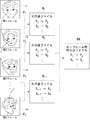
図4は、キーフレームデータとキーフレーム間対応点データが関連づけられた画像データを説明する図である。キーフレームデータKF1とキーフレームデータKF2の間に、それらのキーフレーム間の対応点データKM1が挿入される形で、キーフレームデータ、キーフレーム間対応点データの順に、画像データが格納される。キーフレームデータ記憶部30は、キーフレームデータ32とキーフレーム間対応点ファイル34をこのような形式で格納してもよく、画像送信部22がユーザ端末40に画像データを送信する際、このような形式に変換してもよい。また、キーフレームデータはJPEGなどの画像圧縮方法により、それ自体で圧縮する。またキーフレーム間対応点データについても、文書圧縮方法により圧縮してもよい。
【0029】
図5は、画像データの復号方法を示すフローチャートである。ユーザ端末40の画像受信部42は、画像符号化装置10の画像送信部22から送信される画像データを受信し、画像データからキーフレームデータを抽出し(S40)、キーフレーム間対応点データを抽出する(S42)。画像復号部44は、キーフレーム間対応点データに基づいてキーフレーム間の中間フレームを復元する(S44)。画像表示部46は、キーフレームと中間フレームにより連続した画像を再現し、表示する(S46)。
【0030】
上記の説明では、キーフレーム間の対応関係が取得できると、中間フレーム間の対応点情報を破棄し、キーフレームデータとキーフレーム間の対応情報ファイルのみをユーザ端末40に送信したが、中間フレーム間の対応点情報の少なくとも一部を破棄せずにユーザ端末40に提供するようにしてもよい。これにより連続画像の再現性を高めることができる。また、別の方法として、中間フレーム間の対応点の軌跡を関数として表現して、その関数データをユーザ端末40に提供するようにしてもよい。
【0031】
図6は、軌跡関数データの一例を説明する図である。第1フレームの点P1は、第2フレームでは点P2に、第3フレームでは点P3に、・・・、第nフレームでは点Pnに対応する。キーフレーム上の対応点である点P1と点Pnを通り、中間点P2からPn−1の軌跡を近似する関数をLとする。関数Lは、一例としてNURBS関数、ベジェ(Bezier)関数などのパラメトリック関数である。領域追跡部20は、画像フレーム間の対応点情報ファイルを参照し、適当なパラメトリック関数をあてはめて軌跡関数データ37を得る。軌跡を関数表現することにより、たとえば関数の次元nを減らすことにより、元の対応点情報ファイルの容量よりも小さい容量で対応点の軌跡を表現することができる。さらに、関数で軌跡を表現することにより、画像フレームが存在しないところでも対応点の位置を表現できるので、コマ数を増やして連続画像を再現することもできる。
【0032】
図7は、キーフレームの対応点データと軌跡関数データを対応づけて格納した軌跡関数ファイル36の説明図である。軌跡関数ファイル36は、キーフレームの対応点データと、その対応点が中間フレームにおいて移動した軌跡を近似する軌跡関数データを対応づけて格納する。ユーザ端末40は、軌跡関数ファイル36を用いて、中間フレームを復号し、連続画像を再生することができる。
【0033】
以上述べたように、本実施形態の画像マッチング方法を用いた画像符号化装置によれば、中間フレームを破棄し、キーフレームとキーフレーム間対応点情報ファイルを保存することにより、画像を圧縮符号化できる。また、キーフレーム間の対応関係は、中間フレーム間のマッチングを繰り返すことにより生成されるため、キーフレーム間を直接マッチング計算するよりも正確な情報が得られる。
【0034】
以上、本発明をいくつかの実施の形態をもとに説明した。これらの実施の形態は例示であり、それらの各構成要素や各処理プロセスの組合せにいろいろな変形例が可能なこと、またそうした変形例も本発明の範囲にあることは当業者に理解されるところである。
【0035】
そのような変形例として、上記の説明では動画像を例にマッチング処理を説明したが、本発明は、動画像に限らず、異なる複数の視点から撮影された被写体の画像や、医療現場におけるCTスキャンなどによる患部の断面画像にも適用することができる。これらの画像は、空間軸に沿って連続的に展開された画像データであるから、動画像と同様に画像フレームの集まりとみなすことができる。したがって上記の説明と同様、隣接する画像フレーム間の対応点を順次たどり、隣接しない画像フレーム間の画像領域の対応関係を抽出することができる。
【0036】
【発明の効果】
本発明によれば、連続する画像フレームを符号化してデータ量を削減することができる。
【図面の簡単な説明】
【図1】 実施形態に係る画像処理システムの構成図である。
【図2】 フレーム間の対応点が順次統合される様子を説明する図である。
【図3】 隣接フレーム間の対応関係を順次統合してキーフレーム間の対応関係を生成するマッチング方法のフローチャートである。
【図4】 キーフレームデータとキーフレーム間対応点データが関連づけられた画像データを説明する図である。
【図5】 画像データの復号方法を示すフローチャートである。
【図6】 軌跡関数データの一例を説明する図である。
【図7】 キーフレームの対応点データと軌跡関数データを対応づけて格納した軌跡関数ファイルの説明図である。
【符号の説明】
10 画像符号化装置、 12 画像データ記憶部、 14 画像読込部、 16 マッチング処理部、 18 対応点情報統合部、 20 領域追跡部、 22 画像送信部、24 テンポラリデータ記憶部、26 画像フレームデータ、 28 フレーム間対応点ファイル、 30 キーフレームデータ記憶部、 32 キーフレームデータ、 34 キーフレーム間対応点ファイル、 36 軌跡関数ファイル、 40 ユーザ端末、 42 画像受信部、 44 画像復号部、 46 画像表示部。[0001]
BACKGROUND OF THE INVENTION
The present invention relates to an image compression technique. In particular, the present invention relates to an image matching method for matching between image frames and compressing an image, and an image processing method and apparatus capable of using the method.
[0002]
[Prior art]
Technology for digitizing video with high precision is rapidly progressing in both hardware and software, and it is now possible to shoot and play back moving images for a long time. Moving image data taken with a digital video camera can be imported into a computer and sent as an e-mail attachment for communication, or used for 3D CG modeling, rendering, animation, etc. It has spread. Along with this, higher quality of images has been increasingly desired, and the industry has been competing to increase the density of imaging elements of cameras and increase the speed of imaging processing.
[0003]
[Problems to be solved by the invention]
Thus, in order to improve the quality of moving image data, it is necessary to increase both the number of pixels and the number of image frames, and it is inevitable that the digital image data has a large capacity. However, considering recording image data in a small semiconductor memory mounted on a portable camera, recording captured images on a hard disk of a personal computer, and sending and receiving e-mails over the Internet, Increasing the capacity of data makes it difficult to handle image data, and it will collide with practical storage media capacity limits and communication speed limits, making it difficult to promote the use of image data. In such a situation, there is no doubt that the technology for compressing moving image data is a key factor both technically and practically.
[0004]
In medical practice, techniques such as CT and MRI are used to take cross-sectional images of the affected area of a patient in order to make a more accurate diagnosis. A number of cross-sectional images in the vicinity of the affected area are taken while continuously changing the cross-section. High quality image data is required for diagnosis. In this field as well, a series of continuous image data is used in order to address the problem of large patient diagnosis data stored in medical institutions. There is a need for compression technology.
[0005]
The present invention has been made in view of such problems, and an object thereof is to provide a technique for encoding moving image data.
[0006]
Another object of the present invention is to provide an image processing technique that contributes to improving the recording efficiency of continuous image data, not limited to moving image data.
[0007]
[Means for Solving the Problems]
One aspect of the present invention is a method of processing n first to nth image frames. This method calculates the matching between the first and second image frames, the second and third image frames,..., The (n−1) th and nth image frames, respectively, An adjacent matching process for generating corresponding point information files between frames, and (n-1) files generated in the adjacent matching process are sequentially integrated, so that the first and nth image frames are finally obtained. And generating one corresponding point information file. Corresponding points are arbitrary regions on an image that are associated with each other between image frames, and include image points, a set of points, continuous or discontinuous specific parts, lines such as contours and edges, and the like. The corresponding point information file describes the correspondence between image frames for such corresponding points. For example, when the “region” is a point, information on the coordinates of the image frames in the corresponding relationship is stored. The
[0008]
The method may further include storing a trajectory between the first to nth image frames in the form of a function for at least one image region. The trajectory is obtained by sequentially tracing corresponding points between image frames, and the function representing the trajectory may be a parametric function such as a NURBS function or a Bezier function that approximates the trajectory.
[0009]
The method may further include saving the first and nth image frames as key frames together with corresponding point information files between the first and nth image frames. The key frame and the corresponding point information file may be stored in association with each other. In the storing process, an image frame that cannot be satisfactorily matched in the adjacent matching process may be stored as a key frame. The corresponding point information file may be generated by the integration even for such key frames that are not matched.
[0010]
The method may further include a step of using the first and nth image frames as key frames, compressing the key frames in the frame, and storing the compressed frames together with corresponding point information files between the first and nth image frames. For intra-frame compression, an image compression method such as JPEG may be used. The corresponding point information file may be compressed and saved by dictionary compression or Huffman compression.
[0011]
Another aspect of the present invention is an image processing apparatus. This apparatus includes an image reading unit, a matching processing unit, a temporary storage unit, a corresponding point information file integration unit, and a key frame storage unit. The image reading unit accepts input of continuous image frames. The matching processing unit sequentially calculates matching between two adjacent image frames of the continuous image frames, and calculates corresponding point information files between these image frames (hereinafter also referred to as “adjacent frame corresponding point information files”). Generate. The temporary storage unit stores the corresponding point information files that are sequentially generated. The corresponding point information file integration unit sequentially integrates the stored corresponding point information files to correspond to a corresponding point information file between key frames serving as a starting point and an ending point of integration (hereinafter also referred to as “inter-key frame corresponding point information file”). ) Is generated. The key frame storage unit stores the key frame and the corresponding point information file between the key frames in association with each other. Image frames other than key frames are also referred to as “intermediate frames” below.
[0012]
In order to reproduce the continuous image frames, the image processing apparatus may further include a transmission unit that transmits the key frame and a corresponding point information file between the key frames to a user terminal. The key frame storage unit may temporarily store the key frame and the inter-key frame corresponding point information file, and discard the data after the transmission by the transmission unit.
[0013]
The at least one image region further includes a region tracking unit that tracks a trajectory between the continuous image frames using the corresponding point information file and acquires the trajectory as function data, and the key frame storage unit includes the function frame Data may also be saved. The “image region” is an arbitrary region on the image, and includes a point on the image, a set of points, a continuous or discontinuous specific part, a line such as a contour or an edge. The region tracking unit may acquire the locus of the corresponding points between the key frames moving through the intermediate frames by sequentially tracing the corresponding points stored in the corresponding point information file between adjacent frames, and convert it into a function. Further, the area tracking unit may sequentially follow the corresponding points stored in the inter-key frame corresponding point information file over a plurality of key frames, acquire the trajectory of the corresponding point moving the key frame, and convert it into a function.
[0014]
The corresponding point information integration unit terminates the integration process by using the image frame preceding the pair as the end point of integration when the matching between the two adjacent image frame pairs of the continuous image frames is not achieved. Then, the next integration process may be started with the image frame after the pair as a new starting point. The key frame storage unit may store a pair of image frames that cannot be matched well as a key frame.
[0015]
Another embodiment of the present invention is a computer-readable recording medium. The recording medium calculates matching between two adjacent image frames among consecutive image frames, and generates a corresponding point information file between the image frames, and the corresponding point information file are sequentially integrated. Storing a program for causing a computer to execute a function for generating a corresponding point information file between key frames serving as an integration start point and an end point, and a function for providing the corresponding point information file between the key frame and the key frame in association with each other Do it.
[0016]
Another embodiment of the present invention relates to an image processing method. This method obtains a plurality of corresponding point files describing corresponding points between key frames, and generates a new corresponding point file based on them. This method may generate a new corresponding point file by acquiring a plurality of corresponding point files and integrating them in the time axis direction. In addition to such integration, for example, bilinear interpolation (bilinear) of the corresponding point file between key frames taken from a viewpoint that changes the object in the vertical direction and the corresponding point file between key frames taken from the viewpoint that changes in the horizontal direction. One correspondence file may be generated by blending by interpolation. Further, it may further include a process of generating an intermediate frame between the key frames by interpolation based on the generated new corresponding point file. In any case, the feature of this aspect is that a new corresponding point file is formed from a plurality of corresponding point files.
It should be noted that any combination of the above-described components, and the present invention expressed as a system including a server and a client are also effective as an aspect of the present invention.
[0017]
DETAILED DESCRIPTION OF THE INVENTION
FIG. 1 is a configuration diagram of an image processing system according to the present embodiment. In the image processing system, the
[0018]
The
[0019]
The corresponding point
[0020]
The
[0021]
The
[0022]
FIG. 2 is a diagram illustrating a state in which corresponding points between frames are sequentially integrated. In the continuous image frames F1, F2, F3,..., Fn, the trajectories of the image regions P1, P2, P3,. The matching
[0023]
The matching
[0024]
The matching
[0025]
FIG. 3 is a flowchart of a matching method for sequentially generating correspondences between key frames by sequentially integrating correspondences between adjacent frames. The start frame number s is set to 1, and the number n of frames to be integrated is set to N (S10). The start frame number s is substituted for the frame number variable i (S12). An image frame Fi is input (S14). The image frame Fi + 1 is input (S16). The matching
[0026]
The corresponding point
[0027]
If the matching is not good in process S20 (N in S20), variable i is substituted for variable k (S30), and process S32 is performed. If the matching is not good, it means that the image frames Fs to Fi are continuous moving images, but the image frames Fi + 1 have become discontinuous images due to, for example, scene switching. In this case, the corresponding point information files from the image frames Fs to Fi are integrated using the image frames Fs and Fi as key frames, and the matching process and the integration process are performed from the image frame Fi + 1 onward as the starting point of the image frame Fi + 1. Become.
[0028]
FIG. 4 is a diagram for explaining image data in which key frame data and key frame corresponding point data are associated with each other. Corresponding point data KM1 between the key frames is inserted between the key frame data KF1 and the key frame data KF2, and the image data is stored in the order of the key frame data and the inter-key frame corresponding point data. The key frame data storage unit 30 may store the
[0029]
FIG. 5 is a flowchart showing a method for decoding image data. The
[0030]
In the above description, when the correspondence between the key frames can be acquired, the corresponding point information between the intermediate frames is discarded, and only the correspondence information file between the key frame data and the key frame is transmitted to the
[0031]
FIG. 6 is a diagram illustrating an example of trajectory function data. The point P1 of the first frame corresponds to the point P2 in the second frame, the point P3 in the third frame,..., And the point Pn in the nth frame. Let L be a function that approximates the locus of Pn−1 from the intermediate point P2 through points P1 and Pn, which are corresponding points on the key frame. The function L is a parametric function such as a NURBS function or a Bezier function as an example. The
[0032]
FIG. 7 is an explanatory diagram of the
[0033]
As described above, according to the image coding apparatus using the image matching method of the present embodiment, an intermediate frame is discarded, and a key frame and an inter-key frame corresponding point information file are stored, thereby compressing an image. Can be In addition, since the correspondence between key frames is generated by repeating matching between intermediate frames, more accurate information can be obtained than when direct matching calculation is performed between key frames.
[0034]
The present invention has been described based on some embodiments. It is understood by those skilled in the art that these embodiments are exemplifications, and that various modifications can be made to combinations of the respective constituent elements and processing processes, and such modifications are also within the scope of the present invention. By the way.
[0035]
As such a modification, in the above description, the matching process has been described by taking a moving image as an example. However, the present invention is not limited to a moving image, and an image of a subject captured from a plurality of different viewpoints or a CT in a medical field. The present invention can also be applied to a cross-sectional image of an affected part by scanning or the like. Since these images are image data continuously developed along the spatial axis, they can be regarded as a collection of image frames in the same manner as a moving image. Accordingly, as in the above description, the corresponding points between adjacent image frames can be sequentially traced, and the correspondence relationship of image areas between non-adjacent image frames can be extracted.
[0036]
【The invention's effect】
According to the present invention, it is possible to reduce the amount of data by encoding continuous image frames.
[Brief description of the drawings]
FIG. 1 is a configuration diagram of an image processing system according to an embodiment.
FIG. 2 is a diagram illustrating a state in which corresponding points between frames are sequentially integrated.
FIG. 3 is a flowchart of a matching method for sequentially generating correspondences between key frames by sequentially integrating correspondences between adjacent frames.
FIG. 4 is a diagram for explaining image data in which key frame data and key frame corresponding point data are associated with each other.
FIG. 5 is a flowchart illustrating a method for decoding image data.
FIG. 6 is a diagram illustrating an example of trajectory function data.
FIG. 7 is an explanatory diagram of a trajectory function file that stores key point corresponding point data and trajectory function data in association with each other.
[Explanation of symbols]
DESCRIPTION OF
Claims (8)
1≦i≦n−1なる整数iのそれぞれについて、第iと第(i+1)の画像フレーム間の対応し合う点を検出するための所定のマッチング処理を行い、第iと第(i+1)の画像フレーム間で対応し合う点の座標を対にして記述する第i対応点情報ファイルを生成する隣接マッチング過程と、
第1の画像フレーム上にとられた注目点の第2の画像フレームにおける対応点を求め、この対応点を新たな注目点としてその第3の画像フレームにおける対応点を求め、以下同様に、前画像フレーム上にとられた注目点の現画像フレームにおける対応点を特定し、これを現画像フレーム上にとられた注目点として次画像フレームにおける対応点を特定する処理を隣接画像フレーム間で順次繰り返し、最終的に、第1の画像フレーム上にとられた前記注目点の第nの画像フレームにおける対応点を特定し、第1の画像フレーム上にとられた前記注目点とその第nの画像フレームにおける対応点の座標を対にして直接記述する、統合されたひとつの対応点情報ファイルを生成する過程と、
を含むことを特徴とする画像マッチング方法。A method of processing n image frames from first to nth,
For each integer i satisfying 1 ≦ i ≦ n−1, a predetermined matching process is performed to detect corresponding points between the i-th and (i + 1) -th image frames, and the i-th and (i + 1) -th images are detected. An adjacent matching process for generating an i-th corresponding point information file describing a pair of coordinates of corresponding points between image frames;
The corresponding point in the second image frame of the attention point taken on the first image frame is obtained, the corresponding point in the third image frame is obtained using this corresponding point as a new attention point, and so on. The corresponding point in the current image frame of the attention point taken on the image frame is identified, and the process of identifying the corresponding point in the next image frame as the attention point taken on the current image frame is sequentially performed between adjacent image frames Repeatedly, finally identifying the corresponding point in the nth image frame of the point of interest taken on the first image frame, and the point of interest taken on the first image frame and its nth A process for generating an integrated corresponding point information file that directly describes a pair of coordinates of corresponding points in an image frame;
An image matching method comprising:
1≦i≦n−1なる整数iのそれぞれについて、第iと第(i+1)の画像フレーム間の対応し合う点を検出するための所定のマッチング処理を行い、第iと第(i+1)の画像フレーム間で対応し合う点の座標を対にして記述する第i対応点情報ファイルを生成するマッチング処理部と、
前記生成された第i対応点情報ファイルを記憶する一時記憶部と、
前記記憶された第i対応点情報ファイルを利用して、第1の画像フレーム上にとられた注目点の第2の画像フレームにおける対応点を求め、この対応点を新たな注目点としてその第3の画像フレームにおける対応点を求め、以下同様に、前画像フレーム上にとられた注目点の現画像フレームにおける対応点を特定し、これを現画像フレーム上にとられた注目点として次画像フレームにおける対応点を特定する処理を隣接画像フレーム間で順次繰り返し、最終的に、第1の画像フレーム上にとられた前記注目点の第nの画像フレームにおける対応点を特定し、第1の画像フレーム上にとられた前記注目点とその第nの画像フレームにおける対応点の座標を対にして直接記述する、統合されたひとつの対応点情報ファイルを生成する対応点情報ファイル統合部と、
前記第1と第nの画像フレームをキーフレームとし、それらのキーフレームと前記統合されたひとつの対応点情報ファイルとを関連づけて保存するキーフレーム記憶部と、
を含むことを特徴とする画像処理装置。An image reading unit for receiving inputs of n image frames from the first to the nth;
For each integer i satisfying 1 ≦ i ≦ n−1, a predetermined matching process is performed to detect corresponding points between the i-th and (i + 1) -th image frames, and the i-th and (i + 1) -th images are detected. A matching processing unit for generating an i-th corresponding point information file describing a pair of coordinates of corresponding points between image frames;
A temporary storage unit for storing the generated i-th corresponding point information file;
Using the stored i-th corresponding point information file, a corresponding point in the second image frame of the attention point taken on the first image frame is obtained, and this corresponding point is used as a new attention point. The corresponding points in the third image frame are obtained, and similarly, the corresponding point in the current image frame of the attention point taken on the previous image frame is specified, and this is used as the attention point taken on the current image frame. The process of specifying the corresponding point in the frame is sequentially repeated between adjacent image frames, and finally the corresponding point in the nth image frame of the point of interest taken on the first image frame is specified, described directly in pairs the coordinates of the corresponding point in the image frame of the point of interest taken in the image frame and its first n, corresponding point information off to produce the corresponding point information file one integrated And yl integration unit,
A key frame storage unit that stores the first and nth image frames as key frames, and stores the key frames and the integrated one corresponding point information file in association with each other;
An image processing apparatus comprising:
第1の画像フレーム上にとられた注目点の第2の画像フレームにおける対応点を求め、この対応点を新たな注目点としてその第3の画像フレームにおける対応点を求め、以下同様に、前画像フレーム上にとられた注目点の現画像フレームにおける対応点を特定し、これを現画像フレーム上にとられた注目点として次画像フレームにおける対応点を特定する処理を隣接画像フレーム間で順次繰り返し、最終的に、第1の画像フレーム上にとられた前記注目点の第nの画像フレームにおける対応点を特定し、第1の画像フレーム上にとられた前記注目点とその第nの画像フレームにおける対応点の座標を対にして直接記述する、統合されたひとつの対応点情報ファイルを生成する機能と、
前記第1と第nの画像フレームをキーフレームとし、それらのキーフレームと前記統合されたひとつの対応点情報ファイルとを関連づけて提供する機能と、
をコンピュータに実行せしめることを特徴とするコンピュータプログラム。For detecting a corresponding point between the i-th and (i + 1) -th image frames for each of the integers i satisfying 1 ≦ i ≦ n−1 among the first to n-th image frames. A function of performing a predetermined matching process and generating an i-th corresponding point information file describing a pair of coordinates of corresponding points between the i-th and (i + 1) -th image frames;
The corresponding point in the second image frame of the attention point taken on the first image frame is obtained, the corresponding point in the third image frame is obtained using this corresponding point as a new attention point, and so on. The corresponding point in the current image frame of the attention point taken on the image frame is identified, and the process of identifying the corresponding point in the next image frame as the attention point taken on the current image frame is sequentially performed between adjacent image frames Repeatedly, finally identifying the corresponding point in the nth image frame of the point of interest taken on the first image frame, and the point of interest taken on the first image frame and its nth A function for generating a single integrated corresponding point information file that directly describes the coordinates of corresponding points in an image frame as a pair;
A function of providing the first and n-th image frames as key frames and associating the key frames with the integrated one corresponding point information file;
A computer program for causing a computer to execute.
Priority Applications (4)
| Application Number | Priority Date | Filing Date | Title |
|---|---|---|---|
| JP2001152262A JP3859989B2 (en) | 2000-10-30 | 2001-05-22 | Image matching method and image processing method and apparatus capable of using the method |
| US09/983,949 US20020051489A1 (en) | 2000-10-30 | 2001-10-26 | Image matching method, and image processing apparatus and method using the same |
| EP20010309141 EP1202578A3 (en) | 2000-10-30 | 2001-10-29 | Image matching method, and image processing apparatus and method using the same |
| EP20070012476 EP1830581A1 (en) | 2000-10-30 | 2001-10-29 | Image matching method and apparatus |
Applications Claiming Priority (3)
| Application Number | Priority Date | Filing Date | Title |
|---|---|---|---|
| JP2000330297 | 2000-10-30 | ||
| JP2000-330297 | 2000-10-30 | ||
| JP2001152262A JP3859989B2 (en) | 2000-10-30 | 2001-05-22 | Image matching method and image processing method and apparatus capable of using the method |
Publications (2)
| Publication Number | Publication Date |
|---|---|
| JP2002204458A JP2002204458A (en) | 2002-07-19 |
| JP3859989B2 true JP3859989B2 (en) | 2006-12-20 |
Family
ID=26603022
Family Applications (1)
| Application Number | Title | Priority Date | Filing Date |
|---|---|---|---|
| JP2001152262A Expired - Fee Related JP3859989B2 (en) | 2000-10-30 | 2001-05-22 | Image matching method and image processing method and apparatus capable of using the method |
Country Status (3)
| Country | Link |
|---|---|
| US (1) | US20020051489A1 (en) |
| EP (2) | EP1830581A1 (en) |
| JP (1) | JP3859989B2 (en) |
Families Citing this family (7)
| Publication number | Priority date | Publication date | Assignee | Title |
|---|---|---|---|---|
| JP2002359842A (en) * | 2001-05-31 | 2002-12-13 | Monolith Co Ltd | Method and device for encoding image, and method and device for decoding image |
| JP4355156B2 (en) * | 2002-04-16 | 2009-10-28 | パナソニック株式会社 | Image decoding method and image decoding apparatus |
| JP2004056599A (en) * | 2002-07-22 | 2004-02-19 | Monolith Co Ltd | Image distribution system and charging method usable in the image distribution system |
| JPWO2005122593A1 (en) * | 2004-06-14 | 2008-04-10 | 株式会社モノリス | Video encoding method and video decoding method |
| JPWO2007069350A1 (en) * | 2005-12-12 | 2009-05-21 | 株式会社モノリス | Image encoding and decoding method and apparatus |
| JP6098286B2 (en) * | 2013-03-28 | 2017-03-22 | 大日本印刷株式会社 | Corresponding point determination device, corresponding point determination method, and program |
| DE102021204020B3 (en) | 2021-04-22 | 2022-08-25 | Siemens Healthcare Gmbh | Method for transmitting a plurality of medical images |
Family Cites Families (16)
| Publication number | Priority date | Publication date | Assignee | Title |
|---|---|---|---|---|
| US5111410A (en) * | 1989-06-23 | 1992-05-05 | Kabushiki Kaisha Oh-Yoh Keisoku Kenkyusho | Motion analyzing/advising system |
| US5305400A (en) * | 1990-12-05 | 1994-04-19 | Deutsche Itt Industries Gmbh | Method of encoding and decoding the video data of an image sequence |
| US5600731A (en) * | 1991-05-09 | 1997-02-04 | Eastman Kodak Company | Method for temporally adaptive filtering of frames of a noisy image sequence using motion estimation |
| US5442400A (en) * | 1993-04-29 | 1995-08-15 | Rca Thomson Licensing Corporation | Error concealment apparatus for MPEG-like video data |
| JP3287685B2 (en) * | 1994-02-02 | 2002-06-04 | キヤノン株式会社 | Data conversion device and method |
| EP0720383B1 (en) * | 1994-12-30 | 2000-09-13 | Daewoo Electronics Co., Ltd | Method and apparatus for detecting motion vectors in a frame decimating video encoder |
| KR0171154B1 (en) * | 1995-04-29 | 1999-03-20 | 배순훈 | Method and apparatus for encoding video signals using feature point based motion prediction |
| US5774593A (en) * | 1995-07-24 | 1998-06-30 | University Of Washington | Automatic scene decomposition and optimization of MPEG compressed video |
| US6037988A (en) * | 1996-03-22 | 2000-03-14 | Microsoft Corp | Method for generating sprites for object-based coding sytems using masks and rounding average |
| US6008851A (en) * | 1996-05-23 | 1999-12-28 | The Regents Of The University Of California | Method and apparatus for video data compression |
| US5973742A (en) * | 1996-05-24 | 1999-10-26 | Lsi Logic Corporation | System and method for performing motion estimation with reduced memory loading latency |
| US6067367A (en) * | 1996-10-31 | 2000-05-23 | Yamatake-Honeywell Co., Ltd. | Moving direction measuring device and tracking apparatus |
| JP2927350B2 (en) * | 1997-03-27 | 1999-07-28 | 株式会社モノリス | Multi-resolution filter processing method and image matching method using the method |
| US6445409B1 (en) * | 1997-05-14 | 2002-09-03 | Hitachi Denshi Kabushiki Kaisha | Method of distinguishing a moving object and apparatus of tracking and monitoring a moving object |
| US5969772A (en) * | 1997-10-30 | 1999-10-19 | Nec Corporation | Detection of moving objects in video data by block matching to derive a region motion vector |
| WO2000033253A1 (en) * | 1998-11-24 | 2000-06-08 | Synapix, Inc. | Viewer for optical flow through a 3d time sequence |
-
2001
- 2001-05-22 JP JP2001152262A patent/JP3859989B2/en not_active Expired - Fee Related
- 2001-10-26 US US09/983,949 patent/US20020051489A1/en not_active Abandoned
- 2001-10-29 EP EP20070012476 patent/EP1830581A1/en not_active Withdrawn
- 2001-10-29 EP EP20010309141 patent/EP1202578A3/en not_active Withdrawn
Also Published As
| Publication number | Publication date |
|---|---|
| US20020051489A1 (en) | 2002-05-02 |
| JP2002204458A (en) | 2002-07-19 |
| EP1202578A2 (en) | 2002-05-02 |
| EP1202578A3 (en) | 2003-10-01 |
| EP1830581A1 (en) | 2007-09-05 |
Similar Documents
| Publication | Publication Date | Title |
|---|---|---|
| Liu et al. | Image compression with edge-based inpainting | |
| US7242850B2 (en) | Frame-interpolated variable-rate motion imaging system | |
| US8374444B2 (en) | Method and apparatus for providing higher resolution images in an embedded device | |
| US8289411B2 (en) | Image processing apparatus, program, and method for performing preprocessing for movie reproduction of still images | |
| JP5193291B2 (en) | System and method for generating and playing 3D video files based on 2D video media standards | |
| JP2016527791A (en) | Image processing method and apparatus | |
| CA2488925A1 (en) | Method for producing stereoscopic images from monoscopic images | |
| JPH1079944A (en) | Video information encoding method utilizing object boundary block union/division | |
| US7733379B2 (en) | Composite still-image creating device capable of creating a still image from moving images | |
| JP3859989B2 (en) | Image matching method and image processing method and apparatus capable of using the method | |
| CN110913118B (en) | Video processing method, device and storage medium | |
| US11095901B2 (en) | Object manipulation video conference compression | |
| JP2017192080A (en) | Image compression device, image decoding device, image compression method, and image compression program | |
| JP6245819B2 (en) | Image processing apparatus and image processing method | |
| Kavitha et al. | A survey of image compression methods for low depth-of-field images and image sequences | |
| JP3759538B2 (en) | Image signal processing method and image signal transmission apparatus | |
| JP2002077844A (en) | Apparatus and method for transmitting image as well as image transmission program recording computer readable recording medium | |
| Chubach et al. | Analysis/synthesis coding of dynamic textures based on motion distribution statistics | |
| TW536918B (en) | Method to increase the temporal resolution of continuous image series | |
| CN115086730B (en) | Subscription video generation method, subscription video generation system, computer equipment and subscription video generation medium | |
| US20230105436A1 (en) | Generative adversarial network for video compression | |
| JP6245818B2 (en) | IMAGING DEVICE AND IMAGING DEVICE CONTROL METHOD | |
| CN117319582A (en) | Method and device for human action video acquisition and fluent synthesis | |
| JP6192319B2 (en) | Image processing apparatus and image processing method | |
| JP2003339003A (en) | Image photographing distribution apparatus and image photographing distribution method |
Legal Events
| Date | Code | Title | Description |
|---|---|---|---|
| A131 | Notification of reasons for refusal |
Free format text: JAPANESE INTERMEDIATE CODE: A131 Effective date: 20050315 |
|
| A521 | Request for written amendment filed |
Free format text: JAPANESE INTERMEDIATE CODE: A523 Effective date: 20050512 |
|
| A02 | Decision of refusal |
Free format text: JAPANESE INTERMEDIATE CODE: A02 Effective date: 20060214 |
|
| A521 | Request for written amendment filed |
Free format text: JAPANESE INTERMEDIATE CODE: A523 Effective date: 20060405 |
|
| A911 | Transfer to examiner for re-examination before appeal (zenchi) |
Free format text: JAPANESE INTERMEDIATE CODE: A911 Effective date: 20060510 |
|
| TRDD | Decision of grant or rejection written | ||
| A01 | Written decision to grant a patent or to grant a registration (utility model) |
Free format text: JAPANESE INTERMEDIATE CODE: A01 Effective date: 20060919 |
|
| A61 | First payment of annual fees (during grant procedure) |
Free format text: JAPANESE INTERMEDIATE CODE: A61 Effective date: 20060920 |
|
| R150 | Certificate of patent or registration of utility model |
Free format text: JAPANESE INTERMEDIATE CODE: R150 |
|
| S111 | Request for change of ownership or part of ownership |
Free format text: JAPANESE INTERMEDIATE CODE: R313113 |
|
| S531 | Written request for registration of change of domicile |
Free format text: JAPANESE INTERMEDIATE CODE: R313531 |
|
| FPAY | Renewal fee payment (event date is renewal date of database) |
Free format text: PAYMENT UNTIL: 20090929 Year of fee payment: 3 |
|
| R350 | Written notification of registration of transfer |
Free format text: JAPANESE INTERMEDIATE CODE: R350 |
|
| FPAY | Renewal fee payment (event date is renewal date of database) |
Free format text: PAYMENT UNTIL: 20090929 Year of fee payment: 3 |
|
| R371 | Transfer withdrawn |
Free format text: JAPANESE INTERMEDIATE CODE: R371 |
|
| S111 | Request for change of ownership or part of ownership |
Free format text: JAPANESE INTERMEDIATE CODE: R313113 |
|
| FPAY | Renewal fee payment (event date is renewal date of database) |
Free format text: PAYMENT UNTIL: 20090929 Year of fee payment: 3 |
|
| R350 | Written notification of registration of transfer |
Free format text: JAPANESE INTERMEDIATE CODE: R350 |
|
| FPAY | Renewal fee payment (event date is renewal date of database) |
Free format text: PAYMENT UNTIL: 20100929 Year of fee payment: 4 |
|
| FPAY | Renewal fee payment (event date is renewal date of database) |
Free format text: PAYMENT UNTIL: 20100929 Year of fee payment: 4 |
|
| FPAY | Renewal fee payment (event date is renewal date of database) |
Free format text: PAYMENT UNTIL: 20110929 Year of fee payment: 5 |
|
| FPAY | Renewal fee payment (event date is renewal date of database) |
Free format text: PAYMENT UNTIL: 20120929 Year of fee payment: 6 |
|
| FPAY | Renewal fee payment (event date is renewal date of database) |
Free format text: PAYMENT UNTIL: 20130929 Year of fee payment: 7 |
|
| LAPS | Cancellation because of no payment of annual fees |