JP3856436B2 - Biosensor - Google Patents
Biosensor Download PDFInfo
- Publication number
- JP3856436B2 JP3856436B2 JP2002056190A JP2002056190A JP3856436B2 JP 3856436 B2 JP3856436 B2 JP 3856436B2 JP 2002056190 A JP2002056190 A JP 2002056190A JP 2002056190 A JP2002056190 A JP 2002056190A JP 3856436 B2 JP3856436 B2 JP 3856436B2
- Authority
- JP
- Japan
- Prior art keywords
- filter
- supply path
- biosensor according
- sample solution
- biosensor
- Prior art date
- Legal status (The legal status is an assumption and is not a legal conclusion. Google has not performed a legal analysis and makes no representation as to the accuracy of the status listed.)
- Expired - Fee Related
Links
Images


Landscapes
- Investigating Or Analysing Biological Materials (AREA)
- Apparatus Associated With Microorganisms And Enzymes (AREA)
- Measuring Or Testing Involving Enzymes Or Micro-Organisms (AREA)
Description
【0001】
【発明の属する技術分野】
本発明は、試料中の特定成分を迅速、高感度かつ簡便に定量することができるバイオセンサ、特に総コレステロール、HDLコレステロールまたはLDLコレステロールを測定し得るバイオセンサに関する。
【0002】
【従来の技術】
従来のバイオセンサの一例として代表的なグルコースセンサは、絶縁性基板上にスクリーン印刷などの方法により、少なくとも測定極および対極を含む電極系を形成し、この電極系上に、親水性高分子、酸化還元酵素および電子メディエータを含む酵素反応層を形成して得られる。酸化還元酵素としてはグルコースオキシダーゼなどが用いられ、電子メディエータとしてはフェリシアン化カリウムなどの金属錯体またはフェロセン誘導体もしくはキノン誘導体などの有機化合物が用いられる。さらに酵素反応層には、必要に応じて緩衝剤が加えられる。
【0003】
そして、得られたバイオセンサの酵素反応層上に基質を含む試料液を滴下すると、酵素反応層が溶解して酵素と基質が反応し、この反応に伴って電子メディエータが還元される。酵素反応終了後、還元された電子メディエータを電気化学的に酸化し、その酸化電流値から試料液中の基質濃度を求めることができるのである。例えば、酵素反応の結果生じた電子メディエータの還元体を電極で酸化し、その酸化電流値からグルコース濃度を求めることができる。
【0004】
このようなバイオセンサは、測定対象物質を基質とする酵素を用いることで、様々な物質を測定することが原理的には可能である。例えば、酸化還元酵素にコレステロールオキシダーゼまたはコレステロールデヒドロゲナーゼを用いれば、各種医療機関で診断指針に用いられる血清中のコレステロール値を測定することができる。
この場合、コレステロールエステラーゼの酵素反応の進行は非常に遅いので、適切な界面活性剤を添加することにより、コレステロールエステラーゼの活性を向上させ、全体の反応に要する時間を短縮することができるが、反応系に含まれる界面活性剤が血球に悪影響を及ぼすため、グルコースセンサのように全血そのものを測定することは不可能である。
【0005】
これに対し、血球をろ過した血漿のみを迅速にセンサ内(試料液供給路)に供給するために、試料液供給路の開口部付近にフィルタ(血球ろ過部)を設けることが提案されている。
図5にその概略断面図を示した3種類のフィルタ装置を用い、血球を分離する方法は下記のように3つに分類できる。
【0006】
▲1▼血液(全血)をフィルタの一次側部分の側端部に滴下し、水平方向においてろ過し、フィルタの二次側部分の端部から血漿をにじみ出させる水平分離(Lateral Separation)方式(図5の(a))。
▲2▼血液をフィルタの上表面に直接滴下し、垂直方向においてろ過し、前記フィルタの底面またはその付近の端部から血漿をにじみ出させる垂直分離(Vertical Separation)方式(図5の(b))。
▲3▼血液をフィルタの一次側部分の上表面の一部に直接滴下して、垂直方向においてろ過するとともに水平方向においてもろ過し、フィルタの二次側部分の端部から血漿がにじみ出させる複合分離(Combination)方式(図5の(c))。
【0007】
従来からは、水平分離方式(例えば、特願2000−399056号明細書)または複合分離方式(例えば、特願2001−152868号明細書)が用いられている。
ところが、フィルタが適していないと、フィルタ内に捕捉される血球が破壊され、ヘモグロビンが溶出してしまう。ヘモグロビン程度の小さい血球成分をフィルタでろ過することは困難であり、試料液供給路内にヘモグロビンが流入し、測定誤差の原因となってしまう。
【0008】
ここで、一種類のフィルタだけを用いた血球分離の従来例が、例えば特願2001−180362号明細書に記載されているが、ここではフィルタの孔径と分布が不均一なフィルタを用い、血球がフィルタの内部を厚さ方向に流れている間に、徐々に血球を除去していく。しかし、捕捉比率が100%ではないことから、しばしば血球が試料液供給路に混入してしまうという問題がある。
【0009】
そして、二種類以上のフィルタを用いた血球分離の従来例が、例えば米国特許第5,240,862号明細書(出願人:X-Flor B.V. ; Primecare B.V.)および国際公開第96/15453号パンフレット(出願人:Spectral Diagnostic Inc.)などに記載されている。ここでは、試料液を孔径の大きいフィルタから孔径の小さいフィルタへと順に通過させることを特徴とする。換言すると、試料液が、入口から出口に向かうにしたがって、大きい孔径のフィルタから次第に小さい孔径のフィルタへと通過していく点に特徴を有する。
【0010】
【発明が解決しようとする課題】
しかし、上記のような二種類以上のフィルタを用いる技術において、血球を通過させない捕捉比率100%のフィルタを最下層に設ける場合、その二次側部分から得られた少量のろ液を、圧力を加えることなく、重力などの自然落下などによって、中空の試料液供給路へ移動させることが不可能であるという問題がある。すなわち、毛細管現象によってろ液を試料液供給路内に導入することが不可能であるという問題がある。
【0011】
そこで、本発明の目的は、上記のような不都合をなくし、最初から血球を通過させない程度の小さい孔径を有するフィルタのみを用い、得られたろ液を圧力なしに毛細管現象によって試料液供給路へ移動させ、空気孔でろ液が止まるように改良されたバイオセンサを提供することにある。
さらに本発明の目的は、高精度で応答性に優れ、全血を測定対象とする総コレステロール、HDLコレステロールまたはLDLコレステロールを測定し得るバイオセンサを提供することにある。
【0012】
【課題を解決するための手段】
本発明は、絶縁性基板、前記基板上に設けられた測定極および対極を有する電極系、少なくとも酸化還元酵素および電子メディエータを含む反応層、前記基板に接し前記反応層を含む試料液供給路、前記試料液供給路の終端部側に設けられた空気孔、試料液を導入するための試料液滴下部、ならびに前記試料液供給路内に侵入せず前記試料液供給路および試料液滴下部の間に設けられかつ前記基板に対して垂直方向において前記試料液をろ過する第1フィルタおよび第2フィルタを具備し、ろ液が毛細管現象によって前記試料液供給路内に吸引され、前記試料液供給路の開口部から前記空気孔に向かって前記基板に対して水平方向に通過するバイオセンサであって、前記第1フィルタおよび/または前記第2フィルタが、測定対象成分以外の物質を除去する機能を有するバイオセンサに関する。
【0013】
このバイオセンサにおいては、前記第2フィルタに、測定対象成分以外の物質を除去する試薬が担持または固定されているのが好ましい。また、前記第1フィルタの孔径が第2フィルタの孔径よりも小さいのが好ましい。
また、前記第1フィルタは、均一な孔径を有するメンブレンフィルタであるのが好ましく、前記第2フィルタは、不均一な孔径を有するデプスフィルタであるのが好ましい。
また、前記第1フィルタおよび前記第2フィルタが互いに接触しているのが好ましく、前記第2フィルタが前記試料液供給路の開口部と接触しているのが好ましい。
【0014】
さらに、前記第1フィルタおよび前記第2フィルタが前記電極系と接触していないのが好ましく、前記第1フィルタおよび前記第2フィルタの垂直方向下部に前記電極系が存在しないのが好ましい。
さらにまた、前記第1フィルタおよび第2フィルタの一次側部分の断面積が、前記試料液供給路の長さ方向に垂直な方向における断面積よりも大きいのが好ましい。
【0015】
また、前記第2フィルタに、高密度コレステロールの成分を前記試料液供給路内に供給しない試薬が含まれているのが好ましい。
また、前記第2フィルタに、低密度コレステロールの成分を前記試料液供給路内に供給しない試薬が含まれているのが好ましい。
また、前記第2フィルタに、超低密度コレステロールの成分を前記試料液供給路内に供給しない試薬が含まれているのが好ましい。
また、前記反応層に、総コレステロールの検出のための試薬系が含まれているのが好ましい。
【0016】
【発明の実施の形態】
上記のように、本発明は、絶縁性基板、前記基板上に設けられた測定極および対極を有する電極系、少なくとも酸化還元酵素および電子メディエータを含む反応層、前記基板および前記反応層を含む試料液供給路、前記試料液供給路の終端部側に設けられた空気孔、試料液を導入するための試料液滴下部、ならびに前記試料液供給路内に侵入せず前記試料液供給路および試料液滴下部の間に設けられかつ垂直方向において前記試料液をろ過する第1フィルタおよび前記第1フィルタの下流側に位置する第2フィルタを具備し、ろ液が毛細管現象によって前記試料液供給路内に吸引され、前記試料液供給路の開口部から前記空気孔に向かって水平方向に通過するバイオセンサであって、前記第1フィルタの平均孔径が第2フィルタの平均孔径よりも小さいことを特徴とするバイオセンサに関する。
【0017】
上述のように、2種類以上の血球分離フィルタを用いる従来の技術においては、一番上のフィルタは前処理に用いられ、一番下のフィルタは最終処理に用いられるものであるため、一番上のフィルタの孔径が一番下のフィルタの孔径よりも小さいことはありえなかった(米国特許第5,240,862号明細書および国際公開第96/15453号パンフレット)。
これに対し、本発明のバイオセンサにおいては、第1フィルタと第2フィルタの2種類のフィルタを使用しているが、第1フィルタの役割はほぼ完全に血球を分離することにあり、第2フィルタに達する血球はごく少量である。第2フィルタの役割は、第1フィルタの二次側部分から出てくるごく少量のろ液を吸収し、このろ液を試料液供給路へ供給することである。
【0018】
孔径の小さい第1フィルタから中空の試料液供給路へ直接ろ液を供給することは、圧力でもかけない限り不可能であるが、第1フィルタと試料液供給路の間に第2フィルタを設けることにより、血球を完全にろ過し、かつ、第2フィルタを経たろ液のみを速やかに試料液供給路内に供給することができる。さらに、血球が試料供給路内に流入することを完全に防止することができ、測定誤差を解消することが可能となる。
【0019】
また、第2フィルタから毛細管現象によって試料液供給路内に速やかにろ液を吸引するためには、試料液供給路の容積が重要であり、本発明においては2μl以下であることが好ましい。一般的に、毛細管現象とは、液体中に細管を立てたときに管内の液面が管外の液面よりも上がる(または下がる)現象をいう。そして、液体の表面張力と管壁との相互作用(付着力)の大きさによって、管内に吸い込まれる液体の量が決まり、太い管を用いた場合よりも細い管を用いた場合のほうが多くの量の液体を管内に吸い込ませることができる。このことから、ろ液を迅速に試料液供給路内に供給するためには、試料液供給路が2μl以下の細管と同等の構造を有するのが好ましい。
【0020】
本発明において用いる電子メディエータとしては、フェリシアン化カリウムの他、コレステロールオキシダーゼなどの酸化還元酵素との電子伝達能を有するレドックス化合物から選択することができる。
酸化還元酵素は、測定対象物を基質とする酵素であり、グルコースを測定対象物とするセンサでは、グルコースオキシダーゼを用いる。診断指針に用いられる血清中のコレステロール値を測定するためには、コレステロールの酸化反応を触媒する酵素コレステロールオキシダーゼまたはコレステロールデヒドロゲナーゼとコレステロールエステルをコレステロールに変化させる過程を触媒する酵素コレステロールエステラーゼとを用いる。コレステロールエステラーゼの酵素反応の進行は非常に遅いため、適切な界面活性剤を添加することにより、コレステロールエステラーゼの活性を向上させ、全体の反応に要する時間を短縮することができる。
【0021】
電子メディエータおよび酸化還元酵素などの試薬を含む反応層は、センサ内の電極系上またはその近傍の位置に配置する。また、電極系を設けた絶縁性基板と、絶縁性基板との間に電極系に試料液を供給するための試料液供給路を形成するカバー部材とを組み合わせる。
そして、本発明に係るバイオセンサにおいては、前記反応層を、前記試料液供給路に露出する部分や試料液供給路の開口部などのいずれの位置に配置してもよい。すなわち、前記反応層は、試料液供給路内であれば絶縁性基板およびカバー部材のいずれに設けてもよい。いずれの位置であっても、導入された試料液によって前記反応層が容易に溶解して電極系に到達できることが好ましい。また、電極系を保護し、形成される反応層の剥離を抑制するために、電極系上に接して親水性高分子層を形成してもよい。
【0022】
電子メディエータを含む層は、その溶解性を高めるために界面活性剤と分離させることが好ましく、また、保存安定性のために、コレステロールの酸化反応を触媒する酵素コレステロールオキシダーゼおよびコレステロールエステラーゼと分離させることが好ましい。
血糖値を測定するバイオセンサでは、試料液が反応層へ導入されるのを容易にするため、電極系上に形成された層などを被覆するように、脂質を含む層を形成する例がある(例えば、特開平2−062952号公報)。本発明のコレステロールを測定するバイオセンサでは、反応層の一部を凍結乾燥法により形成するか(特願2000−018834号明細書)、カバー部材の表面を界面活性剤またはプラズマ照射などにより親水処理するのが好ましい。このような構成を採ると脂質層は設けなくてもよい。
【0023】
親水性高分子としては、例えばエチルセルロース、ヒドロキシプロピルセルロース、カルボキシメチルセルロースなどの水溶性セルロース誘導体、ポリビニルピロリドン、ポリビニルアルコール、ゼラチン、アガロース、ポリアクリル酸およびその塩、デンプンおよびその誘導体、無水マレイン酸の重合体およびその塩、ポリアクリルアミド、メタクリレート樹脂、およびポリ−2−ヒドロキシエチルメタクリレートなどがあげられる。
界面活性剤としては、本発明の効果を損なわないものであればよく、例えばn−オクチル−β−D−チオグルコシド、ポリエチレングリコールモノドデシルエーテル、コール酸ナトリウム、ドデシル−β−マルトシド、ジュークロースモノラウレート、デオキシコール酸ナトリウム、タウロデオキシコール酸ナトリウム、N,N−ビス(3−D−グルコンアミドプロピル)デオキシコールアミドおよびポリオキシエチレン(10)オクチルフェニルエーテルなどがあげられる。
【0024】
脂質を使用する場合、例えばレシチン、ホスファチジルコリン、ホスファチジルエタノールアミンなどのリン脂質を用いるのが好ましく、特に両親媒性脂質を用いるのが好適である。
また、酸化電流の測定方法としては、測定極および対極のみを用いる二電極方式と、これらの電極および参照極を用いる三電極方式とがある。なかでも、三電極方式を用いるほうがより正確な測定が可能である。
【0025】
以下に、図面を参照しながら本発明をより具体的に説明する。
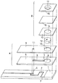
図1は、本発明の好ましい実施の形態に係るバイオセンサの分解斜視図である。図1に示すように、本発明に係るバイオセンサは、例えばポリエチレンテレフタレートなどの絶縁性樹脂からなる絶縁性基板1を有する。図1において、絶縁性基板1の左側上面にパラジウム部分がスパッタ法または蒸着法などによって形成し、レーザートリミングにより作用極2および対極3を含む電極系が形成されている。電極の面積は、後述するスペーサー5上に形成されるスリット8の幅に応じて決定すればよい。
【0026】
絶縁性基板1に組み合わせるスペーサー5には、得られるバイオセンサにおいて試料液供給路を形成するスリット8、スリット8(試料供給路)の開口部7、第2フィルタ12を収納する孔6が形成されている。また、カバー9には第2フィルタ12を収納する孔10と空気孔11が形成され、スペーサー13には孔14が形成され、試料液滴下部16には第1フィルタ15に通じる孔17が形成されている。
上述の絶縁性基板1、スペーサー5、カバー9およびスペーサー13を一体化した際には、スリット8に連なる孔6、カバー9に形成されている孔10およびスペーサー13に形成されている孔14が連通する。
【0027】
血球を分離するための第1フィルタ15は、メンブレンフィルタで構成され、その孔のサイズ(孔径)は血球が通過しない程度(例えば5μm)であればよい。例えば、第1フィルタ15は、一辺6mmの正方形の形状に裁断されている。
血漿を吸引するための第2フィルタ12は、ガラス繊維ろ紙で構成され、直径2.5mm、高さ(厚み)500〜1000μmの円柱状の形状に裁断されている。
【0028】
このセンサを組み立てるには、カバー9とスペーサー5を組み合わせた場合にスリット8により形成される凹状の試料液供給路8’(図2参照)内において、後述のように所定の部材に反応層を形成した後、絶縁性基板1、スペーサー5、カバー9、およびスペーサー13を、これらの右端を一致させて組み合わせる。そして、図1の一点鎖線で示すように、孔6、孔10および孔14から形成される連通孔に第2フィルタ12を設置する。最後に、スペーサー13の上に第1フィルタ15を設置し、さらにその上に試料液滴下部16を設置する。試料液滴下部16の孔17は、第1フィルタ15に通じさせる。
【0029】
ここで、図1の構成にしたがって得られる本発明に係るバイオセンサの概略斜視図を図2に示す。さらに、図2におけるX−X線断面図を図3に示す。なお、図3においては、反応層および電極系などは省略されている。
図3の断面図に示すように、本発明に係るバイオセンサにおいて、試料液である全血から妨害物質である血球を完全に除去するためには、試料液が第1フィルタ15を必ず通過するようにしなければならない。そして、ろ過された血漿を迅速に吸引し、試料液供給路8’へ迅速に供給するために、第2フィルタ12は第1フィルタ15および試料液供給路8’の開口部7と接触していなければならない。
【0030】
図3では、反応層および電極系を省略したが、図4に、反応層および電極系を表した図3に対応する部分拡大図を示す。絶縁性基板1の電極2および3上に、親水性高分子の層18および反応層19aが形成されている。また、試料液供給路8’の天井に相当するカバー9の下面には反応層19bが形成されている。
図1〜4に示すバイオセンサは、その構造をわかりやすくするために5種類の部材を用いて作製されるものである。しかし、スペーサー5とカバー9を一つの部材Aで形成したり、さらにこれらとスペーサー13とを一つの部材Bで形成してもよい。または第2フィルタ12の厚みによってはスペーサー13を除去してもよい。
【0031】
図1〜4に示すバイオセンサを用いて血液中のコレステロールを測定するためには、試料液である血液を試料液滴下部16の孔17に滴下する。ここに全血を滴下すると、第1フィルタ15の一次側部分の上表面で血球のみが捕捉され、二次側部分の下表面から血漿のみがにじみ出てくる。にじみ出てきた血漿は、第2フィルタ12全体を満たす。第2フィルタ内が血漿で飽和した状態になると、血漿は、開口部7から試料液供給路8’内に侵入し、電極系を覆う位置またはカバー9の裏面に担持された反応層を溶解しながら試料液供給路8’内を満たす。すなわち、第2フィルタ12からしみ出した血漿は、電極近傍からさらに空気孔11の部分までの試料液供給路8’全体を満たす。試料液供給路8’全体が液体で満たされると、第2フィルタ12および第1フィルタ15内の液体の流動も停止する。
【0032】
このような血球ろ過の過程を経て、血漿により溶解された反応層と血漿中の測定成分(例えば、コレステロールセンサの場合はコレステロール)との化学反応が生じ、一定時間経過後、電極反応により電流値を測定し、血漿中の成分を定量することができる。
上述のように、図4は、試料液供給路8’の電極系近傍における反応層の配置の例を示す。基板1の電極系上には、カルボキシメチルセルロースのナトリウム塩などの親水性高分子の層18、および例えば電子メディエータなどの反応試薬を含む反応層19aが形成されている。また、カバー9とスペーサー5を組み合わせたカバー部材の裏面には、試料液供給路8’に露出する面に、酸化還元反応酵素を含む反応層19bが形成されている。
【0033】
前記電極系は、貴金属電極であることが好ましい。前記試料液供給路の幅が、好ましくは2mm以下であるため、スクリーンを用いた印刷電極では電極面積を決定する精度が劣るからである。これに対し、貴金属電極は、0.1mm幅でレーザートリミングすることが可能であり、電極面積を決定する精度が高い。
以下に、本発明の実施例を説明するが、本発明はこれらのみに限定されるものではない。
【0034】
【実施例】
《実施例1》
本実施例においては、図1〜4の構成を有する総コレステロールおよびLDLコレステロールを測定するためのバイオセンサを作製した。反応層19aには電子メディエータを添加し、反応層19bにはコレステロールオキシダーゼ、コレステロールエステラーゼおよび界面活性剤を添加した。
まず、絶縁性基板1の電極系上に、カルボキシメチルセルロースのナトリウム塩の0.5wt%水溶液を5μl滴下し、50℃の温風乾燥機中で10分間乾燥させることによりCMCを含む親水性高分子層18を形成した。
つぎに、フェリシアン化カリウム水溶液4μl(フェリシアン化カリウム70mM相当)をCMC層18上に滴下し、50℃の温風乾燥機中で10分間乾燥させることにより、フェリシアン化カリウムを含む反応層19aを形成した。
【0035】
ノカルジア由来のコレステロールオキシダーゼ(EC1.1.3.6、ChOD)とシュードモナス由来のコレステロールエステラーゼ(EC.3.1.1.13、ChE)を溶解した水溶液に、界面活性剤であるポリオキシエチレン(10)オクチルフェニルエーテル(TritonX−100)を添加した。この混合液を、カバー9とスペーサー5とを一体化した部材Aの凹状部分(スリット8、すなわち試料液供給路8’)に0.4μl滴下し、−196℃の液体窒素にて予備凍結後、凍結乾燥機で2時間乾燥させた。これにより、450U/mlコレステロールオキシダーゼ、1125U/mlコレステロールエステラーゼおよび2wt%界面活性剤を含む反応層19bを形成した。
【0036】
第1フィルタは、サイクロポアメンブレン(平均孔径5μm、厚み8〜23μm、Whatman社製)を、四角形に裁断することによって作製した。また、第2フィルタは、Rapid24(最大孔径22μm、厚み約340μm、Whatman社製)を、円形に裁断することによって作製した。
この後、絶縁性基板1と合体部材Aと第2フィルタ12とを一体化して組み合わせた部材を、スペーサー13と第1フィルタ15と試料液滴下部16とを一体化して組み合わせた部材Bに接着することにより、図1〜4に示される構造を有するコレステロールセンサを作製した。
【0037】
《実施例2》
図1〜4の構成を有するLDLコレステロールを測定対象とするバイオセンサを作製し、反応層19aには電子メディエータを含め、反応層19bにはコレステロールオキシダーゼ、コレステロールエステラーゼおよび界面活性剤を含めた。また、第2フィルタ12にはLDL以外のリポ蛋白(HDL、VLDL、CM)が吸着する物質を担持させたこと以外は、実施例1と同様の方法でバイオセンサを作製し、同様の方法で測定を行った。
【0038】
HDLを吸着する物質としては、例えば抗HDL抗体、ポリアニオン(デキストランサルフェート、ヘパリン、リンタングステン酸、ポリビニルサルフェートなど)、2価カチオン(カルシウム、マグネシウム、マンガンなど)がある。VLDL、CMを吸着する物質には、ポリ陰イオン(ヘパリン、デキストラン)、2価陽イオン(マンガン、マグネシウムなど)がある。
【0039】
ここでは、0.1mg/mlヘパリンと、230mMマンガン塩(MnCl2)を第2フィルタ12に滴下し、−196℃の液体窒素にて予備凍結した後、凍結乾燥機で2時間乾燥させた。これにより、LDL以外のリポ蛋白を捕捉することのできる第2フィルタ12を作製した。
【0040】
《実施例3》
図1〜4の構成を有するHDLコレステロールを測定対象とするバイオセンサを作製し、反応層19aには電子メディエータを含め、反応層19bにはコレステロールオキシダーゼ、コレステロールエステラーゼおよび界面活性剤を含めた。また、第2フィルタ12にはHDL以外のリポ蛋白が凝集する物質を含めた。
本実施例においては、第2フィルタ12に、HDL以外のリポ蛋白が凝集する物質を担持させたこと以外は、実施例1と同様の方法でバイオセンサを作製し、同様の方法で測定を行った。具体的には、HDL以外のリポ蛋白が凝集する物質である50mM塩化マグネシウムと1mMリン酸を第2フィルタ12に滴下し、−196℃の液体窒素にて予備凍結した後、凍結乾燥機で2時間乾燥させた。これにより、HDL以外のリポ蛋白を捕捉することのできる第2フィルタ12を作製した。
【0041】
以上のようにして作製したバイオセンサの試料液滴下部16に、試料液として全血10μlを添加し、180秒後に対極を基準にして測定極にアノード方向へ+0.2Vのパルス電圧を印加し、5秒後に作用極と対極との間に流れる電流値を測定した。その結果を図6〜8に示した。
図6は、総コレステロール(HDL、LDL、VLDL、CM)の濃度依存性を表すグラフである。横軸に富士ドライケムの検定値(総コレステロール濃度)を示し、縦軸に実施例1における応答電流値を示している。図7は、LDLコレステロールの濃度依存性を表すグラフである。横軸に富士ドライケムの検定値(LDLコレステロール濃度)を示し、縦軸に実施例2における応答電流値を示している。また、図8は、HDLコレステロールの濃度依存性を表すグラフである。横軸に富士ドライケムの検定値(HDLコレステロール濃度)を示し、縦軸に実施例3における応答電流値を示している。
これらの結果から、試料液を前処理せずにバイオセンサに滴下しただけで、電極系による濃度測定が可能であり、コレステロール濃度と応答値との間に良好な直線性が得られることがわかった。
【0042】
【発明の効果】
本発明によれば、指先穿刺による採血での測定の場合、指先の全血を効率的にセンサに擦り付けたりすることが容易であり、妨害物質である血球をフィルタにより溶血することなく除去し、迅速に電極系へろ液を供給することができる。従って、応答特性に優れたバイオセンサを提供することができる。
【図面の簡単な説明】
【図1】本発明の好ましい実施の形態に係るバイオセンサの分解斜視図である。
【図2】本発明の好ましい実施の形態に係るバイオセンサの合体斜視図である。
【図3】図2に示すバイオセンサの反応層および電極系などを省略したX−X線概略縦断面図である。
【図4】図3に示すバイオセンサの電極系付近の拡大断面図である。
【図5】血球を分離するメカニズムを説明するためのフィルタ装置の概略断面図である。
【図6】本発明の実施例1における総コレステロールに対するバイオセンサの応答特性を示すグラフである。
【図7】本発明の実施例2におけるLDLコレステロールに対するバイオセンサの応答特性を示すグラフである。
【図8】本発明の実施例3におけるHDLコレステロール(c)に対するバイオセンサの応答特性を示すグラフである。
【符号の説明】
1 絶縁性基板
2 作用極
3 対極
4 空気孔
5 スペーサー
6 孔
7 開口部
8 スリット
8’ 試料液供給路
9 カバー
10 孔
11 空気孔
12 第2フィルタ
13 スペーサー
14 孔
15 第1フィルタ
16 試料液滴下部
17 孔
18 親水性高分子層
19a、19b 反応層[0001]
BACKGROUND OF THE INVENTION
The present invention relates to a biosensor capable of quickly, highly sensitively and easily quantifying a specific component in a sample, and more particularly to a biosensor capable of measuring total cholesterol, HDL cholesterol or LDL cholesterol.
[0002]
[Prior art]
A typical glucose sensor as an example of a conventional biosensor forms an electrode system including at least a measurement electrode and a counter electrode on an insulating substrate by a method such as screen printing, on which a hydrophilic polymer, It is obtained by forming an enzyme reaction layer containing an oxidoreductase and an electron mediator. As the oxidoreductase, glucose oxidase or the like is used, and as the electron mediator, a metal complex such as potassium ferricyanide or an organic compound such as ferrocene derivative or quinone derivative is used. Furthermore, a buffering agent is added to the enzyme reaction layer as necessary.
[0003]
Then, when a sample solution containing a substrate is dropped onto the enzyme reaction layer of the obtained biosensor, the enzyme reaction layer is dissolved and the enzyme reacts with the substrate, and the electron mediator is reduced along with this reaction. After the enzymatic reaction is completed, the reduced electron mediator is electrochemically oxidized, and the substrate concentration in the sample solution can be obtained from the oxidation current value. For example, a reduced form of the electron mediator generated as a result of the enzyme reaction is oxidized with an electrode, and the glucose concentration can be determined from the oxidation current value.
[0004]
In principle, such a biosensor can measure various substances by using an enzyme whose substrate is a substance to be measured. For example, if cholesterol oxidase or cholesterol dehydrogenase is used as the oxidoreductase, the cholesterol level in serum used for diagnostic guidelines in various medical institutions can be measured.
In this case, the progress of the enzymatic reaction of cholesterol esterase is very slow. By adding an appropriate surfactant, the activity of cholesterol esterase can be improved and the overall reaction time can be shortened. Since the surfactant contained in the system adversely affects blood cells, it is impossible to measure whole blood itself like a glucose sensor.
[0005]
On the other hand, it has been proposed to provide a filter (blood cell filtration part) in the vicinity of the opening of the sample liquid supply path in order to quickly supply only the plasma obtained by filtering blood cells into the sensor (sample liquid supply path). .
The method of separating blood cells using the three types of filter devices whose schematic sectional views are shown in FIG. 5 can be classified into the following three methods.
[0006]
(1) Horizontal Separation method in which blood (whole blood) is dripped onto the side end of the primary part of the filter, filtered in the horizontal direction, and plasma is oozed out from the end of the secondary part of the filter ( (A) of FIG.
(2) Vertical separation method in which blood is dropped directly on the upper surface of the filter, filtered in the vertical direction, and blood is oozed out from the bottom surface of the filter or the vicinity thereof ((b) in FIG. 5) .
(3) A compound in which blood is dripped directly onto a part of the upper surface of the primary part of the filter and filtered in the vertical direction as well as in the horizontal direction so that the plasma oozes out from the end of the secondary part of the filter. Combination method ((c) of FIG. 5).
[0007]
Conventionally, a horizontal separation system (for example, Japanese Patent Application No. 2000-399056) or a composite separation system (for example, Japanese Patent Application No. 2001-152868) has been used.
However, if the filter is not suitable, blood cells trapped in the filter are destroyed and hemoglobin is eluted. It is difficult to filter a blood cell component as small as hemoglobin with a filter, and hemoglobin flows into the sample solution supply path, causing measurement errors.
[0008]
Here, a conventional example of blood cell separation using only one type of filter is described in, for example, Japanese Patent Application No. 2001-180362. Here, a filter having a nonuniform pore size and distribution is used. While blood is flowing through the filter in the thickness direction, blood cells are gradually removed. However, since the capture ratio is not 100%, there is often a problem that blood cells are mixed into the sample solution supply path.
[0009]
Conventional examples of blood cell separation using two or more types of filters are disclosed in, for example, US Pat. No. 5,240,862 (Applicant: X-Flor BV; Primecare BV) and International Publication No. 96/15453. (Applicant: Spectral Diagnostic Inc.). Here, the sample liquid is passed through a filter with a large pore diameter in order from a filter with a large pore diameter. In other words, the sample liquid is characterized in that it gradually passes from a filter with a large pore diameter to a filter with a small pore diameter as it goes from the inlet to the outlet.
[0010]
[Problems to be solved by the invention]
However, in the technique using two or more types of filters as described above, when a filter with a capture ratio of 100% that does not allow blood cells to pass through is provided in the lowermost layer, a small amount of filtrate obtained from the secondary side portion is subjected to pressure. There is a problem that it is impossible to move to a hollow sample liquid supply path due to natural fall such as gravity without being added. That is, there is a problem that it is impossible to introduce the filtrate into the sample solution supply path by capillary action.
[0011]
Therefore, the object of the present invention is to eliminate the above-mentioned inconveniences and use only a filter having a small pore size that does not allow blood cells to pass from the beginning, and the obtained filtrate is moved to the sample solution supply path by capillary action without pressure. And providing an improved biosensor so that the filtrate stops at the air hole.
A further object of the present invention is to provide a biosensor capable of measuring total cholesterol, HDL cholesterol or LDL cholesterol with high accuracy and excellent responsiveness and measuring whole blood.
[0012]
[Means for Solving the Problems]
The present invention includes an insulating substrate, an electrode system having a measuring electrode and a counter electrode provided on the substrate, a reaction layer including at least an oxidoreductase and an electron mediator, a sample liquid supply path including the reaction layer in contact with the substrate, An air hole provided on the terminal end side of the sample liquid supply path, a lower part of the sample droplet for introducing the sample liquid, and a lower part of the sample liquid supply path and the lower part of the sample liquid droplet that do not enter the sample liquid supply path Between and Against the substrate A first filter and a second filter for filtering the sample solution in a vertical direction; the filtrate is sucked into the sample solution supply path by a capillary phenomenon and is directed from the opening of the sample solution supply path toward the air hole; The Against the substrate The present invention relates to a biosensor that passes in the horizontal direction, wherein the first filter and / or the second filter have a function of removing substances other than the measurement target component.
[0013]
In this biosensor, it is preferable that a reagent for removing substances other than the measurement target component is carried or fixed on the second filter. Moreover, it is preferable that the hole diameter of the said 1st filter is smaller than the hole diameter of a 2nd filter.
The first filter is preferably a membrane filter having a uniform pore size, and the second filter is preferably a depth filter having a non-uniform pore size.
The first filter and the second filter are preferably in contact with each other, and the second filter is preferably in contact with the opening of the sample liquid supply path.
[0014]
Furthermore, it is preferable that the first filter and the second filter are not in contact with the electrode system, and it is preferable that the electrode system is not present in the lower part in the vertical direction of the first filter and the second filter.
Furthermore, it is preferable that a cross-sectional area of the primary side portion of the first filter and the second filter is larger than a cross-sectional area in a direction perpendicular to the length direction of the sample liquid supply path.
[0015]
The second filter preferably contains a reagent that does not supply a high-density cholesterol component into the sample solution supply path.
The second filter preferably contains a reagent that does not supply a low-density cholesterol component into the sample solution supply path.
Moreover, it is preferable that the second filter contains a reagent that does not supply an ultra-low density cholesterol component into the sample solution supply path.
The reaction layer preferably contains a reagent system for detecting total cholesterol.
[0016]
DETAILED DESCRIPTION OF THE INVENTION
As described above, the present invention provides an insulating substrate, an electrode system having a measurement electrode and a counter electrode provided on the substrate, a reaction layer including at least an oxidoreductase and an electron mediator, a sample including the substrate and the reaction layer. A liquid supply path, an air hole provided on the terminal end side of the sample liquid supply path, a lower part of a sample droplet for introducing the sample liquid, and the sample liquid supply path and the sample without entering the sample liquid supply path A first filter that is provided between the lower portions of the droplets and that filters the sample solution in a vertical direction; and a second filter that is positioned downstream of the first filter, and the filtrate is supplied to the sample solution supply path by capillary action. A biosensor that is sucked into the sample solution and passes in the horizontal direction from the opening of the sample solution supply path toward the air hole, wherein the average hole diameter of the first filter is equal to the average hole diameter of the second filter. About biosensors, characterized in that also small.
[0017]
As described above, in the conventional technique using two or more types of blood cell separation filters, the top filter is used for preprocessing and the bottom filter is used for final processing. The pore size of the upper filter could not be smaller than the pore size of the bottom filter (US Pat. No. 5,240,862 and WO 96/15453).
On the other hand, in the biosensor of the present invention, two types of filters, the first filter and the second filter, are used. The role of the first filter is to completely separate blood cells. Only a small amount of blood cells reach the filter. The role of the second filter is to absorb a very small amount of filtrate coming out from the secondary side portion of the first filter and to supply this filtrate to the sample solution supply path.
[0018]
Although it is impossible to supply filtrate directly from the first filter having a small pore diameter to the hollow sample liquid supply path unless pressure is applied, a second filter is provided between the first filter and the sample liquid supply path. Thus, blood cells can be completely filtered, and only the filtrate that has passed through the second filter can be quickly supplied into the sample solution supply path. Furthermore, blood cells can be completely prevented from flowing into the sample supply path, and measurement errors can be eliminated.
[0019]
Further, the volume of the sample liquid supply path is important in order to quickly suck the filtrate from the second filter into the sample liquid supply path by capillary action. In the present invention, the volume is preferably 2 μl or less. Generally, the capillary phenomenon refers to a phenomenon in which the liquid level in the pipe rises (or falls) from the liquid level outside the pipe when a capillary is erected in the liquid. The amount of liquid sucked into the pipe is determined by the surface tension of the liquid and the size of the interaction (adhesion force) with the pipe wall. An amount of liquid can be drawn into the tube. Therefore, in order to quickly supply the filtrate into the sample solution supply path, the sample solution supply path preferably has a structure equivalent to a 2 μl or smaller capillary.
[0020]
The electron mediator used in the present invention can be selected from redox compounds having the ability to transfer electrons with oxidoreductases such as cholesterol oxidase in addition to potassium ferricyanide.
The oxidoreductase is an enzyme that uses a measurement object as a substrate, and glucose oxidase is used in a sensor that uses glucose as a measurement object. In order to measure the cholesterol level in serum used as a diagnostic guide, an enzyme cholesterol oxidase or cholesterol dehydrogenase that catalyzes the oxidation reaction of cholesterol and an enzyme cholesterol esterase that catalyzes the process of changing cholesterol ester to cholesterol are used. Since the progress of the enzymatic reaction of cholesterol esterase is very slow, the activity of cholesterol esterase can be improved and the time required for the whole reaction can be shortened by adding an appropriate surfactant.
[0021]
A reaction layer containing a reagent such as an electron mediator and an oxidoreductase is disposed on or near the electrode system in the sensor. Further, an insulating substrate provided with an electrode system and a cover member that forms a sample solution supply path for supplying the sample solution to the electrode system between the insulating substrate and the insulating substrate are combined.
In the biosensor according to the present invention, the reaction layer may be disposed at any position such as a portion exposed to the sample solution supply path or an opening of the sample solution supply path. That is, the reaction layer may be provided on either the insulating substrate or the cover member as long as it is in the sample solution supply path. At any position, it is preferable that the reaction layer is easily dissolved by the introduced sample solution and can reach the electrode system. Further, in order to protect the electrode system and suppress peeling of the formed reaction layer, a hydrophilic polymer layer may be formed in contact with the electrode system.
[0022]
The layer containing the electron mediator is preferably separated from the surfactant in order to increase its solubility, and separated from the enzymes cholesterol oxidase and cholesterol esterase that catalyze the oxidation reaction of cholesterol for storage stability. Is preferred.
In biosensors that measure blood glucose levels, there is an example in which a lipid-containing layer is formed so as to cover a layer formed on an electrode system in order to facilitate introduction of a sample solution into a reaction layer. (For example, JP-A-2-062952). In the biosensor for measuring cholesterol according to the present invention, a part of the reaction layer is formed by a freeze-drying method (Japanese Patent Application No. 2000-018834), or the surface of the cover member is subjected to a hydrophilic treatment by a surfactant or plasma irradiation. It is preferable to do this. If such a configuration is adopted, the lipid layer may not be provided.
[0023]
Examples of hydrophilic polymers include water-soluble cellulose derivatives such as ethyl cellulose, hydroxypropyl cellulose, carboxymethyl cellulose, polyvinyl pyrrolidone, polyvinyl alcohol, gelatin, agarose, polyacrylic acid and salts thereof, starch and derivatives thereof, and maleic anhydride. Examples thereof include a coalescence and a salt thereof, polyacrylamide, a methacrylate resin, and poly-2-hydroxyethyl methacrylate.
As the surfactant, any surfactant that does not impair the effects of the present invention can be used. For example, n-octyl-β-D-thioglucoside, polyethylene glycol monododecyl ether, sodium cholate, dodecyl-β-maltoside, jucrose mono Examples thereof include laurate, sodium deoxycholate, sodium taurodeoxycholate, N, N-bis (3-D-gluconamidopropyl) deoxycholamide and polyoxyethylene (10) octylphenyl ether.
[0024]
When lipids are used, for example, phospholipids such as lecithin, phosphatidylcholine, and phosphatidylethanolamine are preferably used, and amphiphilic lipids are particularly preferably used.
As a method for measuring the oxidation current, there are a two-electrode method using only a measurement electrode and a counter electrode, and a three-electrode method using these electrodes and a reference electrode. Of these, more accurate measurement is possible using the three-electrode method.
[0025]
Hereinafter, the present invention will be described more specifically with reference to the drawings.
FIG. 1 is an exploded perspective view of a biosensor according to a preferred embodiment of the present invention. As shown in FIG. 1, the biosensor according to the present invention has an insulating
[0026]
The
When the insulating
[0027]
The
The
[0028]
In order to assemble this sensor, a reaction layer is formed on a predetermined member as will be described later in the concave sample
[0029]
Here, FIG. 2 shows a schematic perspective view of the biosensor according to the present invention obtained according to the configuration of FIG. Further, a cross-sectional view taken along line XX in FIG. 2 is shown in FIG. In FIG. 3, the reaction layer and the electrode system are omitted.
As shown in the cross-sectional view of FIG. 3, in the biosensor according to the present invention, in order to completely remove blood cells that are interfering substances from whole blood that is a sample solution, the sample solution always passes through the
[0030]
Although the reaction layer and the electrode system are omitted in FIG. 3, FIG. 4 shows a partially enlarged view corresponding to FIG. 3 showing the reaction layer and the electrode system. A
The biosensor shown in FIGS. 1-4 is produced using five types of members in order to make the structure easy to understand. However, the
[0031]
In order to measure cholesterol in blood using the biosensor shown in FIGS. 1 to 4, blood as a sample liquid is dropped into the
[0032]
Through this blood cell filtration process, a chemical reaction occurs between the reaction layer dissolved in plasma and the measurement component in the plasma (for example, cholesterol in the case of a cholesterol sensor). Can be measured to quantify the components in plasma.
As described above, FIG. 4 shows an example of the arrangement of the reaction layers in the vicinity of the electrode system of the sample
[0033]
The electrode system is preferably a noble metal electrode. This is because the width of the sample solution supply path is preferably 2 mm or less, so that the accuracy of determining the electrode area is inferior in a printed electrode using a screen. On the other hand, the noble metal electrode can be laser-trimmed with a width of 0.1 mm, and the accuracy of determining the electrode area is high.
Examples of the present invention will be described below, but the present invention is not limited to these examples.
[0034]
【Example】
Example 1
In this example, a biosensor for measuring total cholesterol and LDL cholesterol having the configuration shown in FIGS. Electron mediator was added to the
First, 5 μl of a 0.5 wt% aqueous solution of sodium salt of carboxymethyl cellulose is dropped on the electrode system of the insulating
Next, 4 μl of potassium ferricyanide aqueous solution (corresponding to 70 mM potassium ferricyanide) was dropped on the
[0035]
Polyoxyethylene (Surfactant) is dissolved in an aqueous solution in which cholesterol oxidase derived from Nocardia (EC 1.1.3.6, ChOD) and cholesterol esterase derived from Pseudomonas (EC 3.1.1.13, ChE) are dissolved. 10) Octylphenyl ether (Triton X-100) was added. 0.4 μl of this mixed solution is dropped on the concave portion (
[0036]
The first filter was prepared by cutting a cyclopore membrane (
Thereafter, the member obtained by integrating and combining the insulating
[0037]
Example 2
A biosensor for measuring LDL cholesterol having the configuration shown in FIGS. 1 to 4 was prepared. The
[0038]
Examples of substances that adsorb HDL include anti-HDL antibodies, polyanions (such as dextran sulfate, heparin, phosphotungstic acid, and polyvinyl sulfate) and divalent cations (such as calcium, magnesium, and manganese). Substances that adsorb VLDL and CM include polyanions (heparin, dextran) and divalent cations (manganese, magnesium, etc.).
[0039]
Here, 0.1 mg / ml heparin and 230 mM manganese salt (MnCl 2 ) Was dropped on the
[0040]
Example 3
A biosensor having the configuration of FIGS. 1 to 4 and measuring HDL cholesterol was prepared. The
In this example, a biosensor was prepared in the same manner as in Example 1 except that the
[0041]
10 μl of whole blood is added as a sample solution to the lower part of the
FIG. 6 is a graph showing the concentration dependency of total cholesterol (HDL, LDL, VLDL, CM). The horizontal axis represents the test value (total cholesterol concentration) of Fuji Dry Chem, and the vertical axis represents the response current value in Example 1. FIG. 7 is a graph showing the concentration dependency of LDL cholesterol. The horizontal axis represents the Fuji Dry Chem test value (LDL cholesterol concentration), and the vertical axis represents the response current value in Example 2. FIG. 8 is a graph showing the concentration dependency of HDL cholesterol. The horizontal axis represents the Fuji Dry Chem test value (HDL cholesterol concentration), and the vertical axis represents the response current value in Example 3.
From these results, it is clear that the concentration can be measured by the electrode system just by dropping the sample solution onto the biosensor without pretreatment, and good linearity is obtained between the cholesterol concentration and the response value. It was.
[0042]
【The invention's effect】
According to the present invention, in the case of measurement by blood collection by fingertip puncture, it is easy to efficiently rub the fingertip whole blood against the sensor, and remove blood cells that are interfering substances without hemolysis by a filter, The filtrate can be quickly supplied to the electrode system. Therefore, a biosensor with excellent response characteristics can be provided.
[Brief description of the drawings]
FIG. 1 is an exploded perspective view of a biosensor according to a preferred embodiment of the present invention.
FIG. 2 is a combined perspective view of a biosensor according to a preferred embodiment of the present invention.
3 is a schematic longitudinal sectional view taken along the line XX in which a reaction layer and an electrode system of the biosensor shown in FIG. 2 are omitted.
4 is an enlarged cross-sectional view of the vicinity of an electrode system of the biosensor shown in FIG.
FIG. 5 is a schematic sectional view of a filter device for explaining a mechanism for separating blood cells.
FIG. 6 is a graph showing response characteristics of a biosensor with respect to total cholesterol in Example 1 of the present invention.
FIG. 7 is a graph showing the response characteristic of a biosensor to LDL cholesterol in Example 2 of the present invention.
FIG. 8 is a graph showing response characteristics of a biosensor to HDL cholesterol (c) in Example 3 of the present invention.
[Explanation of symbols]
1 Insulating substrate
2 working electrode
3 Counter electrode
4 Air holes
5 Spacer
6 holes
7 opening
8 Slit
8 'Sample solution supply path
9 Cover
10 holes
11 Air hole
12 Second filter
13 Spacer
14 holes
15 First filter
16 Bottom of sample droplet
17 holes
18 Hydrophilic polymer layer
19a, 19b Reaction layer
Claims (14)
前記第1フィルタおよび/または前記第2フィルタが、測定対象成分以外の物質を除去する機能を有するバイオセンサ。An insulating substrate, an electrode system having a measuring electrode and a counter electrode provided on the substrate, a reaction layer containing at least an oxidoreductase and an electron mediator, a sample solution supply path including the reaction layer in contact with the substrate, and the sample solution supply An air hole provided on the terminal end side of the path, a lower part of the sample droplet for introducing the sample liquid, and provided between the sample liquid supply path and the lower part of the sample liquid droplet without entering the sample liquid supply path And a first filter for filtering the sample solution in a direction perpendicular to the substrate and a second filter located downstream of the first filter, and the filtrate is sucked into the sample solution supply path by capillary action. A biosensor that passes in a horizontal direction with respect to the substrate from the opening of the sample solution supply path toward the air hole,
A biosensor in which the first filter and / or the second filter have a function of removing substances other than the measurement target component.
Priority Applications (6)
| Application Number | Priority Date | Filing Date | Title |
|---|---|---|---|
| JP2002056190A JP3856436B2 (en) | 2002-03-01 | 2002-03-01 | Biosensor |
| EP02790949A EP1482307B1 (en) | 2002-03-01 | 2002-12-27 | Biosensor |
| PCT/JP2002/013875 WO2003074999A1 (en) | 2002-03-01 | 2002-12-27 | Biosensor |
| US10/478,283 US20050072670A1 (en) | 2002-03-01 | 2002-12-27 | Biosensor |
| CNB028111273A CN100339702C (en) | 2002-03-01 | 2002-12-27 | Biosensor |
| DE60222809T DE60222809T2 (en) | 2002-03-01 | 2002-12-27 | BIOSENSOR |
Applications Claiming Priority (1)
| Application Number | Priority Date | Filing Date | Title |
|---|---|---|---|
| JP2002056190A JP3856436B2 (en) | 2002-03-01 | 2002-03-01 | Biosensor |
Publications (3)
| Publication Number | Publication Date |
|---|---|
| JP2003254933A JP2003254933A (en) | 2003-09-10 |
| JP2003254933A5 JP2003254933A5 (en) | 2005-08-04 |
| JP3856436B2 true JP3856436B2 (en) | 2006-12-13 |
Family
ID=28666829
Family Applications (1)
| Application Number | Title | Priority Date | Filing Date |
|---|---|---|---|
| JP2002056190A Expired - Fee Related JP3856436B2 (en) | 2002-03-01 | 2002-03-01 | Biosensor |
Country Status (1)
| Country | Link |
|---|---|
| JP (1) | JP3856436B2 (en) |
Families Citing this family (11)
| Publication number | Priority date | Publication date | Assignee | Title |
|---|---|---|---|---|
| JP4318084B2 (en) | 2002-10-25 | 2009-08-19 | アークレイ株式会社 | Analysis tool |
| GB0414550D0 (en) * | 2004-06-29 | 2004-08-04 | Oxford Biosensors Ltd | Electrochemical sensing method |
| JP3955618B2 (en) * | 2005-01-28 | 2007-08-08 | 松下電器産業株式会社 | Blood processing apparatus and blood introduction method |
| JP4645211B2 (en) * | 2005-02-07 | 2011-03-09 | パナソニック株式会社 | HDL-cholesterol analysis disk and HDL-cholesterol analysis device |
| JP4660768B2 (en) * | 2006-03-28 | 2011-03-30 | 国立大学法人 筑波大学 | Microanalyzer and method for analyzing microsample |
| US7943022B2 (en) * | 2007-09-04 | 2011-05-17 | Lifescan, Inc. | Analyte test strip with improved reagent deposition |
| WO2009046161A1 (en) | 2007-10-05 | 2009-04-09 | Bayer Healthcare Llc | Method of defining electrodes using laser-ablation and dielectric material |
| JP5931709B2 (en) * | 2012-12-12 | 2016-06-08 | 株式会社ティー・ティー・エム | Body fluid component testing equipment |
| CN110087749B (en) * | 2016-09-13 | 2022-07-05 | 海世欧申有限责任公司 | Microfluidic filter device and method of trapping objects in through-hole |
| JP2022506925A (en) * | 2018-11-02 | 2022-01-17 | カルディエーアイ テクノロジーズ リミテッド | Portable electrochemical sensor system and method for analyzing user's health condition |
| WO2020196621A1 (en) * | 2019-03-27 | 2020-10-01 | 富士フイルム株式会社 | Blood test kit and method of separating plasma and serum |
-
2002
- 2002-03-01 JP JP2002056190A patent/JP3856436B2/en not_active Expired - Fee Related
Also Published As
| Publication number | Publication date |
|---|---|
| JP2003254933A (en) | 2003-09-10 |
Similar Documents
| Publication | Publication Date | Title |
|---|---|---|
| US6977032B2 (en) | Biosensor | |
| EP1482307B1 (en) | Biosensor | |
| JP4213361B2 (en) | Biosensor | |
| US7056425B2 (en) | Biosensor | |
| JP4183902B2 (en) | Biosensor | |
| JP4184073B2 (en) | Biosensor | |
| US7611621B2 (en) | Disposable oxygen sensor and method for correcting oxygen effect on oxidase-based analytical devices | |
| JP3856436B2 (en) | Biosensor | |
| WO2003048756A1 (en) | Biosensor | |
| JP3856438B2 (en) | Biosensor | |
| JP3856437B2 (en) | Biosensor | |
| JP2004325384A (en) | Biosensor | |
| JP4913355B2 (en) | Biosensor | |
| JP4100196B2 (en) | Biosensor | |
| KR20150111981A (en) | Electrochemical-based analytical test strip with soluble acidic material coating | |
| Hasegawa et al. | Biosensor |
Legal Events
| Date | Code | Title | Description |
|---|---|---|---|
| A521 | Written amendment |
Free format text: JAPANESE INTERMEDIATE CODE: A523 Effective date: 20050107 |
|
| A621 | Written request for application examination |
Free format text: JAPANESE INTERMEDIATE CODE: A621 Effective date: 20050107 |
|
| TRDD | Decision of grant or rejection written | ||
| A01 | Written decision to grant a patent or to grant a registration (utility model) |
Free format text: JAPANESE INTERMEDIATE CODE: A01 Effective date: 20060907 |
|
| A61 | First payment of annual fees (during grant procedure) |
Free format text: JAPANESE INTERMEDIATE CODE: A61 Effective date: 20060911 |
|
| R150 | Certificate of patent or registration of utility model |
Free format text: JAPANESE INTERMEDIATE CODE: R150 |
|
| FPAY | Renewal fee payment (event date is renewal date of database) |
Free format text: PAYMENT UNTIL: 20090922 Year of fee payment: 3 |
|
| FPAY | Renewal fee payment (event date is renewal date of database) |
Free format text: PAYMENT UNTIL: 20100922 Year of fee payment: 4 |
|
| FPAY | Renewal fee payment (event date is renewal date of database) |
Free format text: PAYMENT UNTIL: 20110922 Year of fee payment: 5 |
|
| FPAY | Renewal fee payment (event date is renewal date of database) |
Free format text: PAYMENT UNTIL: 20120922 Year of fee payment: 6 |
|
| FPAY | Renewal fee payment (event date is renewal date of database) |
Free format text: PAYMENT UNTIL: 20130922 Year of fee payment: 7 |
|
| S111 | Request for change of ownership or part of ownership |
Free format text: JAPANESE INTERMEDIATE CODE: R313113 |
|
| S533 | Written request for registration of change of name |
Free format text: JAPANESE INTERMEDIATE CODE: R313533 |
|
| R350 | Written notification of registration of transfer |
Free format text: JAPANESE INTERMEDIATE CODE: R350 |
|
| S111 | Request for change of ownership or part of ownership |
Free format text: JAPANESE INTERMEDIATE CODE: R313113 |
|
| R350 | Written notification of registration of transfer |
Free format text: JAPANESE INTERMEDIATE CODE: R350 |
|
| S111 | Request for change of ownership or part of ownership |
Free format text: JAPANESE INTERMEDIATE CODE: R313113 |
|
| R350 | Written notification of registration of transfer |
Free format text: JAPANESE INTERMEDIATE CODE: R350 |
|
| LAPS | Cancellation because of no payment of annual fees |