JP3856071B2 - Differential scanning calorimeter - Google Patents
Differential scanning calorimeter Download PDFInfo
- Publication number
- JP3856071B2 JP3856071B2 JP01341299A JP1341299A JP3856071B2 JP 3856071 B2 JP3856071 B2 JP 3856071B2 JP 01341299 A JP01341299 A JP 01341299A JP 1341299 A JP1341299 A JP 1341299A JP 3856071 B2 JP3856071 B2 JP 3856071B2
- Authority
- JP
- Japan
- Prior art keywords
- heating furnace
- temperature
- cooling means
- cooling
- condensation
- Prior art date
- Legal status (The legal status is an assumption and is not a legal conclusion. Google has not performed a legal analysis and makes no representation as to the accuracy of the status listed.)
- Expired - Lifetime
Links
Images

Landscapes
- Investigating Or Analyzing Materials Using Thermal Means (AREA)
Description
【0001】
【発明の属する技術分野】
本発明は示差走査熱量計に関し、更に詳しくは、室温以下の温度領域での測定を可能とするための冷却装置を備えた示差走査熱量計に関する。
【0002】
【従来の技術】
示差走査熱量計においては、一般に、試料と参照試料(基準物質)とを加熱炉内に収容して、これら両者の温度を一定の熱的環境下で変化させるとともに、加熱炉内に設けられたDSC(示差走査熱量測定)センサによって試料と参照試料との刻々の温度差に係る情報を検出して、試料の相転位や融解等の熱的性質を測定する。
【0003】
また、この種の装置においては、室温以下の温度領域での測定を行うべく、加熱炉の近傍を直接または間接的に冷却する冷却手段を備えたものが実用化されている。このような冷却手段としては、液体窒素を冷媒とした冷媒槽を用いるものや、液体窒素以外の冷媒とコンプレッサを用いた電気式冷却器を用いるもの等がある。
【0004】
ここで、以上のような冷却手段により加熱炉の近傍を冷却すると、加熱炉の周囲が結露してしまう。このような結露を防止するために、従来、装置全体を窒素雰囲気にてパージしたり、あるいは、大量の断熱材によって装置と周辺空気とを分離するといった対策が採られている。
【0005】
【発明が解決しようとする課題】
ところで、以上のような従来の示差走査熱量計における結露防止の対策では、装置全体が大型化してしまうため、装置の設置のための所要面積が大きくなってしまうという問題がある。また、液体窒素を用いた冷却手段と、それ以外の電気式冷却器を用いた冷却手段ではその冷却能力が大きく相違するため、冷却手段の種類に応じて全く個別の結露防止対策を講じるか、あるいは、液体窒素を用いた冷却手段に合わせた結露防止対策を採用した加熱炉構成とする必要があり、前者の場合は2種類の対策を選択できるような構成が必要となってその構造が複雑化し、あるいは使用に際しての煩雑さが生じ、また、後者の場合には特に電気式冷却器を用いる場合に却って冷却効率が悪化してその最低到達温度が上がってしまうという問題がある。
【0006】
本発明はこのような実情に鑑みてなされたもので、コンパクトな装置構成のもとに、また、冷却能力の相違する冷却手段に対しても容易に対処可能であり、複数種の冷却手段に対して共通に最低到達温度の最小化を図りながら、加熱炉周囲の結露を確実に防止することのできる示差走査熱量計の提供を目的としている。
【0007】
【課題を解決するための手段】
上記の目的を達成するため、本発明の示差走査熱量計は、試料および参照試料を収容してこれらを加熱する加熱炉と、その加熱炉内に配置され、試料と参照試料との刻々の温度差に係る情報を検出するセンサを備えるとともに、室温以下の温度領域での測定を可能とすべく加熱炉の近傍を冷却する冷却手段を備えた示差走査熱量計において、上記加熱炉の周囲に結露防止用ヒータが設けられているとともに、上記冷却手段は、互いに冷却能力が異なり、かつ、選択可能な複数種の冷却手段を有してなり、当該冷却手段の選択状況を判別するための温度センサを備え、上記結露防止用ヒータへの印加電圧は、上記温度センサにより判別された冷却手段の選択状況に基づき、決定されることによって特徴づけられる。
【0008】
本発明は、加熱炉の周囲に設けたヒータの駆動により加熱炉近傍の表面温度のみを上昇させ、これにより、コンパクトな構成のもとに最低到達温度の最小化を図りつつ、加熱炉近傍の冷却時に加熱炉の周囲に結露が生じることを防止しようとするものである。
【0009】
本発明における結露防止用ヒータは、結露が生じない程度に加熱炉近傍の表面温度を上げるだけでよいため小型でよく、また、この結露防止用ヒータに対する印加電圧を変化させるだけで、冷却能力の異なる複数種の冷却手段にも容易に対処可能で、共通に最低到達温度の最小化を達成しつつ確実に結露防止を実現できる。すなわち、冷却能力の異なる複数種の冷却手段の選択状況を温度センサで判別して、その選択状況に応じて結露防止用ヒータに印加する電圧の大きさを決定すること、具体的には、冷却能力の大きい冷却手段が選択されているほど自動的に大きくすることで、最低到達温度に悪影響を与えることなく確実な結露防止が可能となる。
【0010】
【発明の実施の形態】
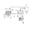
以下、図面を参照しつつ本発明の好適な実施の形態について説明する。図1は本発明の実施の形態の構成図であり、機械的構成の概略を表す模式図と電気的構成を表すブロック図とを併記して示す図である。加熱炉1は、その下方に配置された加熱用ヒータ2の駆動によってその全体が加熱されるとともに、同じく下方に配置された伝熱板3に対して密着している。伝熱板3には、加熱炉1との密着部位に近接してその上面に冷媒槽4が載せられており、この伝熱板3を介して加熱炉1と冷媒槽4とが互いに熱的に結合されている。
【0011】
加熱炉1には、その内部に被測定試料Sおよび参照試料Rを互いに同等の熱的環境のもとに収容するスペースを有し、また、その内部には炉内温度検出用の温度センサ5と、被測定試料Sと参照試料Rとの温度差情報を検出するためのDSCセンサ6が配置されている。温度センサ5による炉内温度検出信号は温度制御回路11に取り込まれ、この温度制御回路11では、その炉内温度の検出結果があらかじめ設定された速度のもとに上昇するように前記した加熱用ヒータ2を駆動制御する。また、DSCセンサ6の出力は測定回路12を経てDSC信号として外部に出力される。
【0012】
この実施の形態においては、室温以下の温度領域での測定に際しては、その温度をある一定温度以下の低温域にまで低下させる必要がある場合には、図1に示すように、冷媒槽4内に液体窒素LNを収容して伝熱板3を介して加熱炉1を冷却する。また、上記のような低温域にまで低下させる必要がない場合には、冷媒槽4内に液体窒素LNを収容することに代えて、図2に要部模式図を示すように、電気式冷却器7を用いる。この電機式冷却器7は、冷媒として液体窒素以外の通常の冷媒を用いたコンプレッサを主体とする冷却器本体71と、その冷却器本体71に接続されて冷却されるコールドヘッド72を有し、そのコールドヘッド72を冷媒槽4の底面位置で伝熱板3に密着させることにより、伝熱板3を介して加熱炉1を冷却することができる。
【0013】
さて、加熱炉1の周囲には結露防止用ヒータ8が配設されているとともに、冷媒槽4の直下の伝熱板3の下面部には冷却手段判定用の温度センサ9が配置されている。結露防止用ヒータ8は、室温以下の温度領域での測定に際して、つまり冷媒槽4内に液体窒素LNを収容するか、あるいは電気式冷却器7を駆動する場合に起動されるものであり、結露防止用制御回路13から供給される電圧信号によって駆動制御される。結露防止用制御回路13では、以下に示すように、冷却手段判定用の温度センサ9の出力信号に基づいて冷却手段の種類を自動的に判別し、その判別結果に基づき、結露防止用ヒータ7に供給すべき電圧信号を変化させる。
【0014】
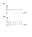
すなわち、結露防止用制御回路13では、温度センサ9による温度検出結果がある一定の温度以下である場合には、冷媒槽4内に液体窒素LNが収容されていると判定し、その場合、図3(A)にタイムチャートを例示するような一定の直流電圧Vが印加される。この直流電圧Vの大きさは、冷媒槽4に液体窒素LNを収容して加熱炉1を冷却した状態において、結露防止用ヒータ8に当該直流電圧Vを印加して加熱炉1の近傍の表面を加熱したときに、加熱炉1の近傍の表面に結露が生じない最低の大きさとされ、その具体的な電圧レベルはあらかじめ実験等によって決定される。
【0015】
一方、温度センサ9による温度検出結果が上記の一定温度を越えている場合には、冷却手段として電気式冷却器7が使用されているものと判定し、その場合には、図3(B)にタイムチャートを例示するように、上記の直流電圧Vを所定の周期でON/OFFしたパルス状の電圧が印加される。このパルス状電圧のパルスデューティは、電気式冷却器7を最大能力のもとに駆動して加熱炉1を冷却した状態において、結露防止用ヒータ8に当該パルス状電圧を印加して加熱炉1の近傍の表面を加熱したときに、加熱炉1の近傍の表面に結露が生じない最低のデューティとされ、その具体的なデューティは上記と同様にあらかじめ実験等によって決定される。
【0016】
以上の本発明の実施の形態によれば、冷却手段として液体窒素LNおよび電気式冷却器7のいずれを選択しても、その冷却手段の種類が自動的に判別され、結露防止用ヒータ8に印加される電圧が各冷却手段の冷却能力に応じた最適の電圧に自動的に設定される。そして、その設定電圧の結露防止用ヒータ8への印加により、冷却手段として液体窒素LNを用いる場合と電気式冷却器7を用いる場合のいずれにおいても、それぞれの冷却能力に基づく加熱炉1の最低到達温度を可及的に低くしながら、加熱炉1の近傍での結露を確実に防止することができる。
【0017】
なお、冷却能力の低い電気式冷却器7を用いる場合の結露防止用ヒータ8の駆動電圧としては、上記のように液体窒素LNを用いる場合に供給する直流電圧Vの絶対値を変化させずにパルス状にチョッピングしたパルス状の電圧とするほか、絶対値を低くした直流電圧としてもよい。
【0018】
【発明の効果】
以上のように、本発明によれば、加熱炉の周囲に結露防止用ヒータを配置して、加熱炉近傍の表面を加熱し得るように構成しているので、室温以下の温度領域での示差走査熱量測定に際して冷却手段により加熱炉を冷却しても、加熱炉近傍に結露が生じることを確実に防止することができ、しかも、冷却能力の異なる複数種の冷却手段のいずれが選択されているかを温度センサで判別し、その判別結果に応じて結露防止用ヒータへの印加電圧を変更するので、冷却能力の異なる複数種の冷却手段のいずれを用いてもその最低到達温度の最小化を図ることができ、コンパクトな装置構成のもとに高性能の示差走査熱量計が得られる。
【図面の簡単な説明】
【図1】本発明の実施の形態の構成図で、機械的構成を表す模式図と電気的構成を表すブロック図とを併記して示す図である。
【図2】本発明の実施の形態において冷却手段として電気式冷却器7を用いた状態を表す要部模式図である。
【図3】本発明の実施の形態における結露防止用ヒータ8への印加電圧波形の例を示すタイムチャートで、(A)は液体窒素LNを用いる場合、(B)は電気式冷却器7を用いる場合をそれぞれ示す図である。
【符号の説明】
1 加熱炉
2 加熱用ヒータ
3 伝熱板
4 冷媒槽
5 温度センサ(炉内温度検出用)
6 DSCセンサ
7 電気式冷却器
8 結露防止用ヒータ
9 温度センサ(冷却手段判別用)
11 温度制御回路
12 測定回路
13 結露防止用制御回路
LN 液体窒素
S 被測定試料
R 参照試料[0001]
BACKGROUND OF THE INVENTION
The present invention relates to a differential scanning calorimeter, and more particularly, to a differential scanning calorimeter equipped with a cooling device for enabling measurement in a temperature region below room temperature.
[0002]
[Prior art]
In a differential scanning calorimeter, generally, a sample and a reference sample (reference material) are accommodated in a heating furnace, and the temperature of both is changed in a constant thermal environment, and is provided in the heating furnace. A DSC (Differential Scanning Calorimetry) sensor detects information related to the temperature difference between the sample and the reference sample, and measures thermal properties such as phase transition and melting of the sample.
[0003]
Also, in this type of apparatus, a device provided with a cooling means for directly or indirectly cooling the vicinity of the heating furnace has been put into practical use in order to perform measurement in a temperature region below room temperature. As such a cooling means, there are one using a refrigerant tank using liquid nitrogen as a refrigerant, and one using an electric cooler using a refrigerant other than liquid nitrogen and a compressor.
[0004]
Here, when the vicinity of the heating furnace is cooled by the cooling means as described above, the surroundings of the heating furnace are condensed. In order to prevent such dew condensation, conventionally, measures such as purging the entire apparatus in a nitrogen atmosphere or separating the apparatus and ambient air with a large amount of heat insulating material have been taken.
[0005]
[Problems to be solved by the invention]
By the way, the countermeasure for preventing condensation in the conventional differential scanning calorimeter as described above has a problem that the entire area of the apparatus is enlarged and a required area for installing the apparatus is increased. Also, the cooling means using liquid nitrogen and the cooling means using other electric coolers are greatly different in cooling capacity. Alternatively, it is necessary to adopt a heating furnace configuration that adopts anti-condensation measures adapted to the cooling means using liquid nitrogen, and in the former case, a configuration in which two types of measures can be selected is required, and the structure is complicated In the latter case, there is a problem that the cooling efficiency is deteriorated and the minimum temperature is raised, particularly when an electric cooler is used.
[0006]
The present invention has been made in view of such circumstances, and can easily cope with cooling means having different cooling capacities based on a compact apparatus configuration, and can be applied to a plurality of types of cooling means. On the other hand, an object of the present invention is to provide a differential scanning calorimeter that can surely prevent condensation around the heating furnace while minimizing the minimum temperature.
[0007]
[Means for Solving the Problems]
In order to achieve the above object, a differential scanning calorimeter of the present invention is provided with a heating furnace that contains a sample and a reference sample and heats them, and is placed in the heating furnace, and the temperature of the sample and the reference sample every moment In a differential scanning calorimeter having a sensor for detecting information related to the difference and a cooling means for cooling the vicinity of the heating furnace so as to enable measurement in a temperature region below room temperature, condensation is formed around the heating furnace. A temperature sensor for determining a selection status of the cooling means, provided with a prevention heater , and the cooling means having a plurality of selectable cooling means having different cooling capacities. And the voltage applied to the dew condensation prevention heater is characterized by being determined based on the selection status of the cooling means determined by the temperature sensor .
[0008]
The present invention raises only the surface temperature in the vicinity of the heating furnace by driving a heater provided around the heating furnace, thereby minimizing the minimum temperature in a compact configuration and in the vicinity of the heating furnace. It is intended to prevent condensation from forming around the heating furnace during cooling.
[0009]
The heater for preventing condensation in the present invention may be small because it only needs to raise the surface temperature in the vicinity of the heating furnace to such an extent that condensation does not occur. Different types of cooling means can be easily handled, and it is possible to reliably prevent condensation while achieving the lowest minimum temperature in common. In other words, the selection status of a plurality of types of cooling means having different cooling capacities is discriminated by the temperature sensor, and the magnitude of the voltage applied to the dew condensation prevention heater is determined according to the selection status. By automatically increasing the cooling means with a larger capacity, it is possible to reliably prevent condensation without adversely affecting the minimum temperature.
[0010]
DETAILED DESCRIPTION OF THE INVENTION
Hereinafter, preferred embodiments of the present invention will be described with reference to the drawings. FIG. 1 is a configuration diagram of an embodiment of the present invention, and is a diagram illustrating a schematic diagram showing an outline of a mechanical configuration and a block diagram showing an electrical configuration. The
[0011]
The
[0012]
In this embodiment, in the measurement in the temperature region below room temperature, when it is necessary to lower the temperature to a low temperature region below a certain temperature, as shown in FIG. Liquid nitrogen LN is accommodated in the
[0013]
Now, along with
[0014]
That is, the dew condensation
[0015]
On the other hand, when the temperature detection result by the
[0016]
According to the embodiment of the present invention described above, selecting one of the liquid nitrogen LN and
[0017]
As the drive voltage of the
[0018]
【The invention's effect】
As described above, according to the present invention, by arranging the anti-condensation heater around the furnace, since the structure so as to heat the surface of the furnace near a differential in the following temperature range room temperature Even if the heating furnace is cooled by the cooling means in scanning calorimetry, it is possible to surely prevent condensation in the vicinity of the heating furnace, and which of the plural kinds of cooling means having different cooling capacities is selected. was determined by a temperature sensor, since changing the voltage applied to the anti-condensation heater in accordance with the determination result, and work to minimize its lowest temperature reached by using any of a plurality of types of cooling means having different cooling capacity Therefore, a high-performance differential scanning calorimeter can be obtained with a compact device configuration.
[Brief description of the drawings]
FIG. 1 is a configuration diagram of an embodiment of the present invention, and is a diagram illustrating a schematic diagram showing a mechanical configuration and a block diagram showing an electrical configuration.
FIG. 2 is a main part schematic diagram showing a state in which an
FIGS. 3A and 3B are time charts showing examples of voltage waveforms applied to the dew
[Explanation of symbols]
DESCRIPTION OF
6
11
Claims (1)
上記加熱炉の周囲に結露防止用ヒータが設けられているとともに、上記冷却手段は、互いに冷却能力が異なり、かつ、選択可能な複数種の冷却手段を有してなり、当該冷却手段の選択状況を判別するための温度センサを備え、上記結露防止用ヒータへの印加電圧は、上記温度センサにより判別された冷却手段の選択状況に基づき、決定されることを特徴とする示差走査熱量計。A heating furnace that contains a sample and a reference sample and heats them, and a sensor that is disposed in the heating furnace and detects information related to the temperature difference between the sample and the reference sample, and a temperature region below room temperature In a differential scanning calorimeter equipped with cooling means for cooling the vicinity of the heating furnace in order to enable measurement at
A heater for preventing condensation is provided around the heating furnace , and the cooling means has a plurality of selectable cooling means having different cooling capacities, and the selection status of the cooling means. A differential scanning calorimeter , further comprising: a temperature sensor for determining whether or not the voltage applied to the dew condensation prevention heater is determined based on a selection state of the cooling means determined by the temperature sensor .
Priority Applications (1)
| Application Number | Priority Date | Filing Date | Title |
|---|---|---|---|
| JP01341299A JP3856071B2 (en) | 1999-01-21 | 1999-01-21 | Differential scanning calorimeter |
Applications Claiming Priority (1)
| Application Number | Priority Date | Filing Date | Title |
|---|---|---|---|
| JP01341299A JP3856071B2 (en) | 1999-01-21 | 1999-01-21 | Differential scanning calorimeter |
Publications (2)
| Publication Number | Publication Date |
|---|---|
| JP2000214114A JP2000214114A (en) | 2000-08-04 |
| JP3856071B2 true JP3856071B2 (en) | 2006-12-13 |
Family
ID=11832433
Family Applications (1)
| Application Number | Title | Priority Date | Filing Date |
|---|---|---|---|
| JP01341299A Expired - Lifetime JP3856071B2 (en) | 1999-01-21 | 1999-01-21 | Differential scanning calorimeter |
Country Status (1)
| Country | Link |
|---|---|
| JP (1) | JP3856071B2 (en) |
Families Citing this family (3)
| Publication number | Priority date | Publication date | Assignee | Title |
|---|---|---|---|---|
| JP4812017B2 (en) * | 2006-07-26 | 2011-11-09 | エスアイアイ・ナノテクノロジー株式会社 | Thermal analysis apparatus and drying method thereof |
| JP6178645B2 (en) * | 2013-07-10 | 2017-08-09 | 大陽日酸株式会社 | Low temperature container for liquefied gas combustion / explosion test and combustion / explosion test apparatus equipped with the container |
| CN108645890B (en) * | 2018-07-20 | 2023-09-19 | 四川建筑职业技术学院 | Testing device and testing method for testing temperature regulating performance of phase-change material |
-
1999
- 1999-01-21 JP JP01341299A patent/JP3856071B2/en not_active Expired - Lifetime
Also Published As
| Publication number | Publication date |
|---|---|
| JP2000214114A (en) | 2000-08-04 |
Similar Documents
| Publication | Publication Date | Title |
|---|---|---|
| JP6792558B2 (en) | Beverage cooling | |
| KR20060082783A (en) | Refrigerator and method for controlling the same | |
| KR930010518A (en) | Temperature control system for heat detectors of heat exchangers | |
| US20070272678A1 (en) | Apparatus and Method of Computer Component Heating | |
| JP3856071B2 (en) | Differential scanning calorimeter | |
| JPH06207771A (en) | Cold and hot storage chamber | |
| US6744021B2 (en) | Microprocessor controlled heater/cooler system | |
| JP2009162479A (en) | Method and device for air conditioning a showcase | |
| KR100277122B1 (en) | Cooling device of Kimchi storage device and its control method | |
| CN1322296C (en) | Refrigerator | |
| JP2796258B2 (en) | Water heater | |
| JP2000126032A (en) | Jar rice cooker | |
| CN1810063A (en) | Microprocessor controlled heater/cooler system | |
| JPH0529677A (en) | Controlling method for drive of piezoelectric laminate | |
| JP3713840B2 (en) | Induction heating rice cooker | |
| KR100202603B1 (en) | Defosting method of refrigerator | |
| KR0176844B1 (en) | Heat storing apparatus and its temperature control method using thermo couple | |
| JPH0768824A (en) | Temperature control device of thermal head | |
| JP2730774B2 (en) | Insulated water heater | |
| JPH07260547A (en) | Water level detecting device | |
| JP3200951B2 (en) | Centrifuge temperature controller | |
| JPH06341691A (en) | Operation control method for air conditioner | |
| KR100432691B1 (en) | Control method of apparatus for protecting dew of kimchi chamber | |
| JPH10132770A (en) | Thermal analysis apparatus | |
| JP2004316989A (en) | Thermostat installing structure of storage shed |
Legal Events
| Date | Code | Title | Description |
|---|---|---|---|
| A621 | Written request for application examination |
Free format text: JAPANESE INTERMEDIATE CODE: A621 Effective date: 20050523 |
|
| A977 | Report on retrieval |
Free format text: JAPANESE INTERMEDIATE CODE: A971007 Effective date: 20060320 |
|
| A131 | Notification of reasons for refusal |
Free format text: JAPANESE INTERMEDIATE CODE: A131 Effective date: 20060404 |
|
| A521 | Written amendment |
Free format text: JAPANESE INTERMEDIATE CODE: A523 Effective date: 20060602 |
|
| TRDD | Decision of grant or rejection written | ||
| A01 | Written decision to grant a patent or to grant a registration (utility model) |
Free format text: JAPANESE INTERMEDIATE CODE: A01 Effective date: 20060823 |
|
| A61 | First payment of annual fees (during grant procedure) |
Free format text: JAPANESE INTERMEDIATE CODE: A61 Effective date: 20060905 |
|
| R150 | Certificate of patent or registration of utility model |
Free format text: JAPANESE INTERMEDIATE CODE: R150 |
|
| FPAY | Renewal fee payment (event date is renewal date of database) |
Free format text: PAYMENT UNTIL: 20090922 Year of fee payment: 3 |
|
| FPAY | Renewal fee payment (event date is renewal date of database) |
Free format text: PAYMENT UNTIL: 20100922 Year of fee payment: 4 |
|
| FPAY | Renewal fee payment (event date is renewal date of database) |
Free format text: PAYMENT UNTIL: 20110922 Year of fee payment: 5 |
|
| FPAY | Renewal fee payment (event date is renewal date of database) |
Free format text: PAYMENT UNTIL: 20110922 Year of fee payment: 5 |
|
| FPAY | Renewal fee payment (event date is renewal date of database) |
Free format text: PAYMENT UNTIL: 20120922 Year of fee payment: 6 |
|
| FPAY | Renewal fee payment (event date is renewal date of database) |
Free format text: PAYMENT UNTIL: 20120922 Year of fee payment: 6 |
|
| FPAY | Renewal fee payment (event date is renewal date of database) |
Free format text: PAYMENT UNTIL: 20130922 Year of fee payment: 7 |
|
| EXPY | Cancellation because of completion of term |