JP3855918B2 - Heat exchanger - Google Patents
Heat exchanger Download PDFInfo
- Publication number
- JP3855918B2 JP3855918B2 JP2002336281A JP2002336281A JP3855918B2 JP 3855918 B2 JP3855918 B2 JP 3855918B2 JP 2002336281 A JP2002336281 A JP 2002336281A JP 2002336281 A JP2002336281 A JP 2002336281A JP 3855918 B2 JP3855918 B2 JP 3855918B2
- Authority
- JP
- Japan
- Prior art keywords
- pipe
- fitting
- heat exchanger
- flange
- connecting pipe
- Prior art date
- Legal status (The legal status is an assumption and is not a legal conclusion. Google has not performed a legal analysis and makes no representation as to the accuracy of the status listed.)
- Expired - Fee Related
Links
Images


Classifications
-
- F—MECHANICAL ENGINEERING; LIGHTING; HEATING; WEAPONS; BLASTING
- F28—HEAT EXCHANGE IN GENERAL
- F28F—DETAILS OF HEAT-EXCHANGE AND HEAT-TRANSFER APPARATUS, OF GENERAL APPLICATION
- F28F9/00—Casings; Header boxes; Auxiliary supports for elements; Auxiliary members within casings
- F28F9/02—Header boxes; End plates
- F28F9/0246—Arrangements for connecting header boxes with flow lines
- F28F9/0256—Arrangements for coupling connectors with flow lines
-
- F—MECHANICAL ENGINEERING; LIGHTING; HEATING; WEAPONS; BLASTING
- F28—HEAT EXCHANGE IN GENERAL
- F28F—DETAILS OF HEAT-EXCHANGE AND HEAT-TRANSFER APPARATUS, OF GENERAL APPLICATION
- F28F9/00—Casings; Header boxes; Auxiliary supports for elements; Auxiliary members within casings
- F28F9/02—Header boxes; End plates
- F28F9/0246—Arrangements for connecting header boxes with flow lines
Landscapes
- Engineering & Computer Science (AREA)
- Physics & Mathematics (AREA)
- Thermal Sciences (AREA)
- Mechanical Engineering (AREA)
- General Engineering & Computer Science (AREA)
- Non-Disconnectible Joints And Screw-Threaded Joints (AREA)
- Details Of Heat-Exchange And Heat-Transfer (AREA)
Description
【0001】
【発明の属する技術分野】
本発明は、流体の入口または出口にフランジ付きパイプ口金を備えた熱交換器であって、自動車空調装置のヒータコアなどに使用される熱交換器に関するものである。
【0002】
【従来の技術】
自動車空調装置のヒータコアなどに使用される熱交換器は、図1に示す如く、流体の入口または出口に、フランジ11が付いたパイプ口金1を備える。このパイプ口金1には、鍔21を有する接続管2の先端が差し込まれ、フランジ11と鍔21とを突き合わせて連結される。パイプ口金1と接続管2の連結方法には、フランジ11と鍔21とを鑞付けする、特殊な形状を有するクランプでネジ止めする、直接ネジ止めをする、フランジ11を特殊な形状にし鍔21にかしめる、などがある。
上記した連結方法のうち、鑞付け以外の方法では、図8に示す如く、シール手段としてOリング23を介装してパイプ口金1と接続管2を連結している(特許文献なし)。
【0003】
【発明が解決しようとする課題】
近年、金属材料のリサイクルが進められる中、自動車空調装置の熱交換器に主として用いられるアルミニウム材料もリサイクルの要望が大きい。この点、上記の如く、口金パイプと接続管の連結部のシール手段として用いられるOリングはゴム製であるため、リサイクルにおいて好ましくない。一方、シール手段として鑞付けを採用すると、リサイクルにおける問題はないが、連結部を加熱する必要がある。このため、接続管の形状によっては加熱炉に入れることができず、別途の手段で連結部を加熱する必要があり作業が煩雑になる。
【0004】
【発明の目的】
本発明の目的は、自動車空調装置の熱交換器の口金パイプと接続管との連結部のシール手段として、Oリングの介装および鑞付けを止め、金属材料としてのリサイクル性の向上、かつ、Oリングの廃止によるコストダウン、または、連結部の加熱の省略に伴う製造工程の簡略化によるコストダウンを可能とする熱交換器の提供にある。
【0005】
【課題を解決するための手段】
〔請求項1の手段〕
請求項1の発明によると、熱交換器のパイプ口金の内面と接続管の差し込み部分の外面とを接着剤で接合し、接続管の差し込み部分の外面に設けた嵌合凹部に、パイプ口金の内面対応部に設けた嵌合凸部を嵌合したことを特徴とする。それによって、接着剤がシール手段として作用し、従来のOリングの介装、鑞付けを廃止することができコストダウンおよびリサイクル性の向上を達成できるとともに、接続管やパイプ口金に急激なトルク負荷などがかかっても、嵌合凹部と嵌合凸部の嵌合により接続管とパイプ口金の連結が強化され、硬化した接着剤における亀裂の発生を防止することができる。
【0006】
〔請求項2の手段〕
請求項2の発明によると、熱交換器のパイプ口金の内面と接続管の差し込み部分の外面とを接着剤で接合し、接続管の差し込み部分の外面に設けた嵌合凸部を、パイプ口金の内面対応部に設けた嵌合凹部に嵌合したことを特徴とする。それによって、請求項1と同様の効果を得ることができる。
【0007】
〔請求項3の手段〕
請求項3の発明によると、熱交換器のパイプ口金の内面と接続管の差し込み部分をテーパ形状とし互いに摺り合わせ、摺り合わせ部同士を接着剤で接合したことを特徴とする。それによって、接着剤の使用量をさらに減らすことができ、さらなるコストダウンが達成できる。
【0008】
〔請求項4の手段〕
請求項4の発明によると、接続管に設けられた嵌合凹部または嵌合凸部が接続管の差し込み部分の外面の最下部に設けられ、パイプ口金の内面対応部に設けた嵌合凸部または嵌合凹部に嵌合したことを特徴とする。それにより、接続管の差し込み部分における嵌合凹部または嵌合凸部の製作加工が容易になる。
【0010】
【発明の実施の形態】
〔比較例の構成〕
本発明の実施形態に対する比較例を図1および図2に示す。熱交換器100は、熱交換部101の左右両端にタンク102、103を有する。熱交換部101は、上下方向に平行に配列された多数の偏平チューブ104と、その偏平チューブ104に接して配された多数のコルゲートフィン105とからなる。タンク102、103の上端には、それぞれフランジ11を有するパイプ口金1が接合されている。
【0011】
パイプ口金1は、平板で円環状のフランジ11と、フランジ11の内周から下方にテーパ状に延長され径小となる嵌合部12と、嵌合部12から下方に延長された径小部13と、径小部13から下方に展長されたテーパ部14と、テーパ部14から下方に延長された溶接部15と、フランジ11の外周から上方に円筒状に延長されたかしめ筒部16とを備える。接続管2は、その下面がフランジ11の上面と突き合わされる鍔21と、鍔21から先端に向かってテーパ状に径小となり、パイプ口金1への差し込み部分を構成するとともに、その外面が嵌合部12の内面と摺り合わされる嵌合部22とを備える。
【0012】
〔比較例の作用および効果〕
このパイプ口金1の嵌合部12に接続管2の嵌合部22を差し込み、フランジ11の上面と鍔21の下面とを突き合わせるとともに、嵌合部12の内面と嵌合部22の外面とを摺り合わせる。この際、嵌合部12の内面と嵌合部22の外面とのいずれか一方に、予め接着剤を塗布しておく。
接着剤としては、アクリル系のものなどが使用されるが、できるだけ短時間で硬化し、硬化後の強度が十分であり、高温劣化、経時劣化せず、耐クーラント性のあるものが使用される。
【0013】
パイプ口金1と接続管2とを連結する際、嵌合部12と嵌合部22とが摺り合わされ、予め塗布された接着剤が硬化して接合しシール機能を有するため、Oリングの介装や鑞付けを行う必要がなく、コストダウンを達成できる。また、接着剤の塗布量はOリングの質量に比べ微量であるため、リサイクル性も向上できる。
【0014】
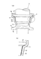
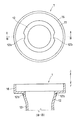
〔第1実施形態の構成〕
本発明の第1実施形態を図3ないし図5に示す。第1実施形態では、図3または図4に示すごとく、パイプ口金1と接続管2との連結を強化するため、パイプ口金1に嵌合凸部12b、12bを設け、接続管2に嵌合凹部22a、22aを設けている。嵌合凹部22a、22aは、接続管2の嵌合部22の外面の最上部に直径方向にほぼ対称となる位置に2つ設けられている。一方、嵌合凸部12b、12bは、パイプ口金1の内面対応部に設けられている。
【0015】
内面対応部とは、パイプ口金1の嵌合部12の内面であり、パイプ口金1の嵌合部12に接続管2の嵌合部22を差し込み、フランジ11の上面と鍔21の下面とを突き合わせた際に、嵌合部22の外面に設けられた嵌合凹部22aまたは後述する嵌合凸部22bが嵌まり込み、嵌合部12の内面と嵌合部22の外面とを摺り合わせることができる位置のことである。
【0016】
〔第1実施形態の作用および効果〕
このパイプ口金1の嵌合部12に接続管2の嵌合部22を差し込み、フランジ11の上面と鍔21の下面とを突き合わせ、嵌合凹部22a、22aに嵌合凸部12b、12bを嵌合させ、嵌合部12の内面と嵌合部22の外面とを摺り合わせる。この際、嵌合部12の内面と嵌合部22の外面とのいずれか一方に、予め接着剤を塗布しておく。
【0017】
これにより、比較例と同様の効果が得られるとともに、嵌合凸部12b、12bと嵌合凹部22a、22aの嵌合によりパイプ口金1と接続管2との連結が強化され、急激なトルク負荷などにより硬化した接着剤の亀裂が発生することを防止することができる。なお、第1実施形態では、接着剤が硬化したのち図5に示すごとく、かしめ筒部16を4箇所でかしめ、さらにパイプ口金1と接続管2との連結が強化されている。
【0018】
〔第2実施形態の構成〕
本発明の第2実施形態を図6に示す。第2実施形態では、図6に示すごとく、パイプ口金1と接続管2との連結を強化するため、パイプ口金1に嵌合凹部12aが、接続管2に嵌合凸部22bが設けられている。嵌合凸部22bは、接続管2の嵌合部22の外面の最上部に1つ設けられている。一方、嵌合凹部12aは、パイプ口金1の内面対応部に設けられている。
【0019】
〔第2実施形態の作用および効果〕
このパイプ口金1の嵌合部12に接続管2の嵌合部22を差し込み、フランジ11の上面と鍔21の下面とを突き合わせ、嵌合凸部22bを嵌合凹部12aに嵌合させ、嵌合部12の内面と嵌合部22の外面とを摺り合わせる。この際、嵌合部12の内面と嵌合部22の外面とのいずれか一方に、予め接着剤を塗布しておく。
これにより、第1実施形態と同様の効果が得られる。なお、第2実施形態でも、接着剤が硬化したのち、かしめ筒部16を4箇所でかしめ、パイプ口金1と接続管2との連結が強化されている。
【0020】
〔第3実施形態の構成〕
本発明の第3実施形態を図7に示す。第3実施形態にかかる接続管2では、嵌合部22の外面の最下部に嵌合凹部22aが、1つ設けられている。一方、パイプ口金1に設けられる嵌合凸部12bは、嵌合部12の内面対応部に設けられている。
【0021】
〔第3実施形態の作用および効果〕
このパイプ口金1の嵌合部12に接続管2の嵌合部22を差し込み、フランジ11の上面と鍔21の下面とを突き合わせ、嵌合凹部22aに嵌合凸部12bを嵌合させ、嵌合部12の内面と嵌合部22の外面とを摺り合わせる。この際、嵌合部12の内面と嵌合部22の外面とのいずれか一方に、予め接着剤を塗布しておく。
【0022】
これにより、第1実施形態または第2実施形態と同様の効果が得られる。また、嵌合凹部22aは嵌合部22の最下部に位置するため、嵌合凹部22aの製作加工が極めて容易にできる。なお、第3実施形態でも、接着剤が硬化したのち、かしめ筒部16を4箇所でかしめ、パイプ口金1と接続管2との連結が強化されている。
【0023】
〔他の実施形態〕
第1実施形態ないしは第3実施形態ではかしめ筒部16をかしめていたが、必ずしもかしめる必要はない。また、嵌合凹部12a、22aおよび嵌合凸部12b、22bは1つまたは2つしか設けられていなかったが、3つ以上設けてもよい。さらに嵌合凹部22aおよび嵌合凸部22bの位置は接続管2の嵌合部22の外面の最下部または最上部に限られるものではなく、最下部と最上部の間で任意の位置を選ぶことができる。これに応じて、パイプ口金1の嵌合部12の内面対応部に設けられる嵌合凹部12aおよび嵌合凸部12bの位置も、変更可能である。
【図面の簡単な説明】
【図1】 比較例における熱交換器、パイプ口金と接続管との連結を示す全体図である。
【図2】 比較例におけるパイプ口金と接続管との連結を示す断面図(a)とその要部拡大図(b)である。
【図3】 第1実施形態における接続管の断面図および下面図である。
【図4】 第1実施形態におけるパイプ口金の平面図および断面図である。
【図5】 第1実施形態におけるパイプ口金と接続管の連結を示す平面図および断面図である。
【図6】 第2実施形態におけるパイプ口金と接続管の連結を示す平面図および断面図である。
【図7】 第3実施形態におけるパイプ口金と接続管の連結を示す平面図および断面図である。
【図8】 従来のパイプ口金と接続管の連結を示す断面図である。
【符号の説明】
1 パイプ口金
11 フランジ
12 嵌合部
12a 嵌合凹部
12b 嵌合凸部
2 接続管
21 鍔
22 嵌合部
22a 嵌合凹部
22b 嵌合凸部
100 熱交換器[0001]
BACKGROUND OF THE INVENTION
The present invention relates to a heat exchanger provided with a flanged pipe cap at the inlet or outlet of a fluid, and relates to a heat exchanger used for a heater core of an automobile air conditioner or the like.
[0002]
[Prior art]
As shown in FIG. 1, a heat exchanger used for a heater core of an automobile air conditioner includes a
Among the connection methods described above, in methods other than brazing, as shown in FIG. 8, the
[0003]
[Problems to be solved by the invention]
In recent years, as metal materials are being recycled, there is a great demand for recycling aluminum materials mainly used for heat exchangers of automobile air conditioners. In this respect, as described above, the O-ring used as a sealing means for the connection portion between the cap pipe and the connecting pipe is made of rubber, and thus is not preferable in recycling. On the other hand, when brazing is adopted as the sealing means, there is no problem in recycling, but the connecting portion needs to be heated. For this reason, depending on the shape of the connecting pipe, it cannot be put into the heating furnace, and it is necessary to heat the connecting portion by a separate means, and the work becomes complicated.
[0004]
OBJECT OF THE INVENTION
The object of the present invention is to stop the interposing and brazing of the O-ring as a sealing means for the connection portion between the cap pipe and the connecting pipe of the heat exchanger of the automobile air conditioner, to improve the recyclability as a metal material, and An object of the present invention is to provide a heat exchanger that can reduce the cost by eliminating the O-ring or simplifying the manufacturing process when the heating of the connecting portion is omitted.
[0005]
[Means for Solving the Problems]
[Means of Claim 1]
According to the first aspect of the present invention, the inner surface of the pipe cap of the heat exchanger and the outer surface of the insertion portion of the connection pipe are joined with an adhesive, and the fitting recess provided on the outer surface of the insertion portion of the connection pipe is connected to the pipe cap. The fitting convex part provided in the inner surface corresponding part was fitted . As a result, the adhesive acts as a sealing means, eliminating conventional O-ring intervention and brazing, reducing costs and improving recyclability, and abrupt torque load on the connection pipe and pipe cap. Even if it is applied, the connection between the connecting pipe and the pipe cap is strengthened by the fitting of the fitting concave portion and the fitting convex portion, and the occurrence of cracks in the cured adhesive can be prevented .
[0006]
[Means of claim 2]
According to the invention of
[0007]
[Means of claim 3]
The invention according to claim 3 is characterized in that the inner surface of the pipe cap of the heat exchanger and the insertion portion of the connecting pipe are tapered and rubbed together, and the rubbed portions are joined together with an adhesive . Thereby, the amount of adhesive used can be further reduced, and further cost reduction can be achieved .
[0008]
[Means of claim 4]
According to invention of Claim 4, the fitting recessed part or fitting convex part provided in the connecting pipe was provided in the lowest part of the outer surface of the insertion part of a connecting pipe, and the fitting convex part provided in the inner surface corresponding part of a pipe cap or it is characterized in that fitted into the mating recess. Thereby, the manufacturing process of the fitting recessed part or the fitting convex part in the insertion part of a connection pipe becomes easy .
[0010]
DETAILED DESCRIPTION OF THE INVENTION
[Configuration of Comparative Example ]
A comparative example for the embodiment of the present invention is shown in FIGS. The
[0011]
The
[0012]
[Operation and effect of comparative example ]
The
Adhesives such as acrylic are used as adhesives, but they are cured in as short a time as possible, have sufficient strength after curing, do not deteriorate at high temperatures and do not deteriorate with time, and are resistant to coolant. .
[0013]
When the
[0014]
[Configuration of First Embodiment]
A first embodiment of the present invention is shown in FIGS. In the first embodiment, as shown in FIG. 3 or FIG. 4,
[0015]
The inner surface corresponding portion is the inner surface of the
[0016]
[Operation and Effect of First Embodiment]
The
[0017]
As a result, the same effects as those of the comparative example can be obtained, and the coupling between the
[0018]
[Configuration of Second Embodiment]
A second embodiment of the present invention is shown in FIG. In the second embodiment, as shown in FIG. 6, the
[0019]
[Operation and Effect of Second Embodiment]
The
Thereby, the effect similar to 1st Embodiment is acquired. Also in the second embodiment, after the adhesive is cured, the
[0020]
[Configuration of Third Embodiment]
A third embodiment of the present invention is shown in FIG. In the connecting
[0021]
[Operation and Effect of Third Embodiment]
The
[0022]
Thereby, the effect similar to 1st Embodiment or 2nd Embodiment is acquired. Further, since the
[0023]
Other Embodiment
In the first or third embodiment, the
[Brief description of the drawings]
FIG. 1 is an overall view showing a connection between a heat exchanger, a pipe cap and a connecting pipe in a comparative example .
FIG. 2 is a cross-sectional view (a) showing a connection between a pipe cap and a connecting pipe in a comparative example, and an enlarged view (b) thereof.
FIGS. 3A and 3B are a cross-sectional view and a bottom view of a connection pipe in the first embodiment. FIGS.
FIGS. 4A and 4B are a plan view and a cross-sectional view of a pipe cap in the first embodiment. FIGS.
FIGS. 5A and 5B are a plan view and a cross-sectional view showing a connection between a pipe cap and a connecting pipe in the first embodiment. FIGS.
FIGS. 6A and 6B are a plan view and a cross-sectional view showing a connection between a pipe cap and a connecting pipe in a second embodiment. FIGS.
FIGS. 7A and 7B are a plan view and a cross-sectional view showing a connection between a pipe cap and a connecting pipe in a third embodiment. FIGS.
FIG. 8 is a cross-sectional view showing the connection between a conventional pipe cap and a connecting pipe.
[Explanation of symbols]
DESCRIPTION OF
Claims (4)
前記パイプ口金の内面と前記接続管の差し込み部分の外面とを接着剤で接合し、
前記接続管の差し込み部分の外面に設けた嵌合凹部に、前記パイプ口金の内面対応部に設けた嵌合凸部を嵌合したことを特徴とする熱交換器。In a heat exchanger provided with a pipe base with a flange having a cylindrical part on the outer periphery at the inlet or outlet of the fluid, inserting a connecting pipe having a flange into the pipe base, and connecting the connecting pipes,
Bonding the inner surface of the pipe base and the outer surface of the insertion portion of the connecting pipe with an adhesive ,
A heat exchanger , wherein a fitting convex portion provided at an inner surface corresponding portion of the pipe base is fitted into a fitting concave portion provided on an outer surface of an insertion portion of the connection pipe .
前記パイプ口金の内面と前記接続管の差し込み部分の外面とを接着剤で接合し、
前記接続管の差し込み部分の外面に設けた嵌合凸部を、前記パイプ口金の内面対応部に設けた嵌合凹部に嵌合したことを特徴とする熱交換器。 In a heat exchanger provided with a pipe base with a flange having a cylindrical part on the outer periphery at the inlet or outlet of the fluid, inserting a connecting pipe having a flange into the pipe base, and connecting the connecting pipes,
Bonding the inner surface of the pipe base and the outer surface of the insertion portion of the connecting pipe with an adhesive,
Heat exchanger, characterized in that the fitting convex portion provided on the outer surface of the insertion portion of the connecting pipe, and fitted into the fitting recess formed on the inner surface corresponding portion of the pipe mouth.
Priority Applications (1)
| Application Number | Priority Date | Filing Date | Title |
|---|---|---|---|
| JP2002336281A JP3855918B2 (en) | 2002-09-20 | 2002-11-20 | Heat exchanger |
Applications Claiming Priority (2)
| Application Number | Priority Date | Filing Date | Title |
|---|---|---|---|
| JP2002274331 | 2002-09-20 | ||
| JP2002336281A JP3855918B2 (en) | 2002-09-20 | 2002-11-20 | Heat exchanger |
Publications (2)
| Publication Number | Publication Date |
|---|---|
| JP2004163073A JP2004163073A (en) | 2004-06-10 |
| JP3855918B2 true JP3855918B2 (en) | 2006-12-13 |
Family
ID=32827679
Family Applications (1)
| Application Number | Title | Priority Date | Filing Date |
|---|---|---|---|
| JP2002336281A Expired - Fee Related JP3855918B2 (en) | 2002-09-20 | 2002-11-20 | Heat exchanger |
Country Status (1)
| Country | Link |
|---|---|
| JP (1) | JP3855918B2 (en) |
Families Citing this family (3)
| Publication number | Priority date | Publication date | Assignee | Title |
|---|---|---|---|---|
| KR100649437B1 (en) * | 2000-11-20 | 2006-11-24 | 한라공조주식회사 | Structure for connecting pipe of heat exchanger |
| KR101740478B1 (en) | 2010-10-12 | 2017-05-26 | 한온시스템 주식회사 | Pipe connecting member of evaporator for vehicle |
| JP6483409B2 (en) * | 2013-12-26 | 2019-03-13 | カルソニックカンセイ株式会社 | Heat exchanger |
-
2002
- 2002-11-20 JP JP2002336281A patent/JP3855918B2/en not_active Expired - Fee Related
Also Published As
| Publication number | Publication date |
|---|---|
| JP2004163073A (en) | 2004-06-10 |
Similar Documents
| Publication | Publication Date | Title |
|---|---|---|
| EP1158260B1 (en) | Heat exchanger, method of manufacturing the heat exchanger, and method of manufacturing tube for heat exchange | |
| US5295302A (en) | Method of manufacturing an aluminum heat exchanger | |
| US20130220585A1 (en) | Tube for heat exchanger | |
| WO2006123535A1 (en) | Heat exchanger | |
| EP2397806B1 (en) | Heater core with connector formed by plates | |
| JP2004219044A (en) | Manufacturing method of heat exchanger and core plate | |
| JP2008260049A (en) | Heat exchanger and its manufacturing method | |
| US20040007040A1 (en) | Method and tool for folding a metal strip | |
| WO2001049443A1 (en) | Heat exchanger | |
| JP3855918B2 (en) | Heat exchanger | |
| US20090188654A1 (en) | Automotive Heater Core | |
| JP4043208B2 (en) | Heat exchanger | |
| CN101776413B (en) | Heat exchanger and manufacturing method thereof | |
| US20090188656A1 (en) | Binding Structure between Tank and Header of Automotive Heater Core | |
| JP2000283692A (en) | Neck filler, and water pouring structure | |
| JPS6176890A (en) | Heat exchanger | |
| KR100948396B1 (en) | Pipe for heat exchangers | |
| US6434824B1 (en) | Process for making a fluid-tight connection between a tube and a plate-shaped part | |
| US20040144526A1 (en) | Metal heat exchanger tank and method of forming same | |
| JP2005127676A (en) | Heat exchanger, and manufacturing method of heat exchanger | |
| JPH11101586A (en) | Flat tube for heat exchanger | |
| JP3027429U (en) | Structure of protector for heat exchanger | |
| JPH0741565Y2 (en) | Pipe with lid for brazing | |
| JP2020143863A (en) | Heat exchanger | |
| JPH0723101Y2 (en) | Brazing jig for aluminum laminated heat exchanger manufacturing |
Legal Events
| Date | Code | Title | Description |
|---|---|---|---|
| A621 | Written request for application examination |
Free format text: JAPANESE INTERMEDIATE CODE: A621 Effective date: 20041220 |
|
| A977 | Report on retrieval |
Free format text: JAPANESE INTERMEDIATE CODE: A971007 Effective date: 20060425 |
|
| A131 | Notification of reasons for refusal |
Free format text: JAPANESE INTERMEDIATE CODE: A131 Effective date: 20060516 |
|
| A521 | Written amendment |
Free format text: JAPANESE INTERMEDIATE CODE: A523 Effective date: 20060713 |
|
| TRDD | Decision of grant or rejection written | ||
| A01 | Written decision to grant a patent or to grant a registration (utility model) |
Free format text: JAPANESE INTERMEDIATE CODE: A01 Effective date: 20060822 |
|
| A61 | First payment of annual fees (during grant procedure) |
Free format text: JAPANESE INTERMEDIATE CODE: A61 Effective date: 20060904 |
|
| R150 | Certificate of patent (=grant) or registration of utility model |
Free format text: JAPANESE INTERMEDIATE CODE: R150 |
|
| LAPS | Cancellation because of no payment of annual fees |