JP3855876B2 - Information recording method, reproducing method, and recording apparatus - Google Patents
Information recording method, reproducing method, and recording apparatus Download PDFInfo
- Publication number
- JP3855876B2 JP3855876B2 JP2002225486A JP2002225486A JP3855876B2 JP 3855876 B2 JP3855876 B2 JP 3855876B2 JP 2002225486 A JP2002225486 A JP 2002225486A JP 2002225486 A JP2002225486 A JP 2002225486A JP 3855876 B2 JP3855876 B2 JP 3855876B2
- Authority
- JP
- Japan
- Prior art keywords
- light
- recording
- information
- light spot
- energy beam
- Prior art date
- Legal status (The legal status is an assumption and is not a legal conclusion. Google has not performed a legal analysis and makes no representation as to the accuracy of the status listed.)
- Expired - Fee Related
Links
Images


Classifications
-
- G—PHYSICS
- G11—INFORMATION STORAGE
- G11B—INFORMATION STORAGE BASED ON RELATIVE MOVEMENT BETWEEN RECORD CARRIER AND TRANSDUCER
- G11B7/00—Recording or reproducing by optical means, e.g. recording using a thermal beam of optical radiation by modifying optical properties or the physical structure, reproducing using an optical beam at lower power by sensing optical properties; Record carriers therefor
- G11B7/12—Heads, e.g. forming of the optical beam spot or modulation of the optical beam
- G11B7/135—Means for guiding the beam from the source to the record carrier or from the record carrier to the detector
- G11B7/1353—Diffractive elements, e.g. holograms or gratings
-
- G—PHYSICS
- G11—INFORMATION STORAGE
- G11B—INFORMATION STORAGE BASED ON RELATIVE MOVEMENT BETWEEN RECORD CARRIER AND TRANSDUCER
- G11B7/00—Recording or reproducing by optical means, e.g. recording using a thermal beam of optical radiation by modifying optical properties or the physical structure, reproducing using an optical beam at lower power by sensing optical properties; Record carriers therefor
- G11B7/004—Recording, reproducing or erasing methods; Read, write or erase circuits therefor
- G11B7/0045—Recording
- G11B7/00456—Recording strategies, e.g. pulse sequences
-
- G—PHYSICS
- G11—INFORMATION STORAGE
- G11B—INFORMATION STORAGE BASED ON RELATIVE MOVEMENT BETWEEN RECORD CARRIER AND TRANSDUCER
- G11B7/00—Recording or reproducing by optical means, e.g. recording using a thermal beam of optical radiation by modifying optical properties or the physical structure, reproducing using an optical beam at lower power by sensing optical properties; Record carriers therefor
- G11B7/004—Recording, reproducing or erasing methods; Read, write or erase circuits therefor
- G11B7/005—Reproducing
-
- G—PHYSICS
- G11—INFORMATION STORAGE
- G11B—INFORMATION STORAGE BASED ON RELATIVE MOVEMENT BETWEEN RECORD CARRIER AND TRANSDUCER
- G11B7/00—Recording or reproducing by optical means, e.g. recording using a thermal beam of optical radiation by modifying optical properties or the physical structure, reproducing using an optical beam at lower power by sensing optical properties; Record carriers therefor
- G11B7/12—Heads, e.g. forming of the optical beam spot or modulation of the optical beam
- G11B7/125—Optical beam sources therefor, e.g. laser control circuitry specially adapted for optical storage devices; Modulators, e.g. means for controlling the size or intensity of optical spots or optical traces
- G11B7/127—Lasers; Multiple laser arrays
-
- G—PHYSICS
- G11—INFORMATION STORAGE
- G11B—INFORMATION STORAGE BASED ON RELATIVE MOVEMENT BETWEEN RECORD CARRIER AND TRANSDUCER
- G11B7/00—Recording or reproducing by optical means, e.g. recording using a thermal beam of optical radiation by modifying optical properties or the physical structure, reproducing using an optical beam at lower power by sensing optical properties; Record carriers therefor
- G11B7/12—Heads, e.g. forming of the optical beam spot or modulation of the optical beam
- G11B7/135—Means for guiding the beam from the source to the record carrier or from the record carrier to the detector
- G11B7/1356—Double or multiple prisms, i.e. having two or more prisms in cooperation
-
- G—PHYSICS
- G11—INFORMATION STORAGE
- G11B—INFORMATION STORAGE BASED ON RELATIVE MOVEMENT BETWEEN RECORD CARRIER AND TRANSDUCER
- G11B7/00—Recording or reproducing by optical means, e.g. recording using a thermal beam of optical radiation by modifying optical properties or the physical structure, reproducing using an optical beam at lower power by sensing optical properties; Record carriers therefor
- G11B7/12—Heads, e.g. forming of the optical beam spot or modulation of the optical beam
- G11B7/135—Means for guiding the beam from the source to the record carrier or from the record carrier to the detector
- G11B7/1365—Separate or integrated refractive elements, e.g. wave plates
-
- G—PHYSICS
- G11—INFORMATION STORAGE
- G11B—INFORMATION STORAGE BASED ON RELATIVE MOVEMENT BETWEEN RECORD CARRIER AND TRANSDUCER
- G11B7/00—Recording or reproducing by optical means, e.g. recording using a thermal beam of optical radiation by modifying optical properties or the physical structure, reproducing using an optical beam at lower power by sensing optical properties; Record carriers therefor
- G11B7/24—Record carriers characterised by shape, structure or physical properties, or by the selection of the material
- G11B7/2407—Tracks or pits; Shape, structure or physical properties thereof
- G11B7/24073—Tracks
- G11B7/24082—Meandering
-
- G—PHYSICS
- G11—INFORMATION STORAGE
- G11B—INFORMATION STORAGE BASED ON RELATIVE MOVEMENT BETWEEN RECORD CARRIER AND TRANSDUCER
- G11B7/00—Recording or reproducing by optical means, e.g. recording using a thermal beam of optical radiation by modifying optical properties or the physical structure, reproducing using an optical beam at lower power by sensing optical properties; Record carriers therefor
- G11B7/24—Record carriers characterised by shape, structure or physical properties, or by the selection of the material
- G11B7/2407—Tracks or pits; Shape, structure or physical properties thereof
- G11B7/24085—Pits
- G11B7/24088—Pits for storing more than two values, i.e. multi-valued recording for data or prepits
-
- G—PHYSICS
- G11—INFORMATION STORAGE
- G11B—INFORMATION STORAGE BASED ON RELATIVE MOVEMENT BETWEEN RECORD CARRIER AND TRANSDUCER
- G11B11/00—Recording on or reproducing from the same record carrier wherein for these two operations the methods are covered by different main groups of groups G11B3/00 - G11B7/00 or by different subgroups of group G11B9/00; Record carriers therefor
- G11B11/10—Recording on or reproducing from the same record carrier wherein for these two operations the methods are covered by different main groups of groups G11B3/00 - G11B7/00 or by different subgroups of group G11B9/00; Record carriers therefor using recording by magnetic means or other means for magnetisation or demagnetisation of a record carrier, e.g. light induced spin magnetisation; Demagnetisation by thermal or stress means in the presence or not of an orienting magnetic field
- G11B11/105—Recording on or reproducing from the same record carrier wherein for these two operations the methods are covered by different main groups of groups G11B3/00 - G11B7/00 or by different subgroups of group G11B9/00; Record carriers therefor using recording by magnetic means or other means for magnetisation or demagnetisation of a record carrier, e.g. light induced spin magnetisation; Demagnetisation by thermal or stress means in the presence or not of an orienting magnetic field using a beam of light or a magnetic field for recording by change of magnetisation and a beam of light for reproducing, i.e. magneto-optical, e.g. light-induced thermomagnetic recording, spin magnetisation recording, Kerr or Faraday effect reproducing
- G11B11/10502—Recording on or reproducing from the same record carrier wherein for these two operations the methods are covered by different main groups of groups G11B3/00 - G11B7/00 or by different subgroups of group G11B9/00; Record carriers therefor using recording by magnetic means or other means for magnetisation or demagnetisation of a record carrier, e.g. light induced spin magnetisation; Demagnetisation by thermal or stress means in the presence or not of an orienting magnetic field using a beam of light or a magnetic field for recording by change of magnetisation and a beam of light for reproducing, i.e. magneto-optical, e.g. light-induced thermomagnetic recording, spin magnetisation recording, Kerr or Faraday effect reproducing characterised by the transducing operation to be executed
- G11B11/10504—Recording
-
- G—PHYSICS
- G11—INFORMATION STORAGE
- G11B—INFORMATION STORAGE BASED ON RELATIVE MOVEMENT BETWEEN RECORD CARRIER AND TRANSDUCER
- G11B11/00—Recording on or reproducing from the same record carrier wherein for these two operations the methods are covered by different main groups of groups G11B3/00 - G11B7/00 or by different subgroups of group G11B9/00; Record carriers therefor
- G11B11/10—Recording on or reproducing from the same record carrier wherein for these two operations the methods are covered by different main groups of groups G11B3/00 - G11B7/00 or by different subgroups of group G11B9/00; Record carriers therefor using recording by magnetic means or other means for magnetisation or demagnetisation of a record carrier, e.g. light induced spin magnetisation; Demagnetisation by thermal or stress means in the presence or not of an orienting magnetic field
- G11B11/105—Recording on or reproducing from the same record carrier wherein for these two operations the methods are covered by different main groups of groups G11B3/00 - G11B7/00 or by different subgroups of group G11B9/00; Record carriers therefor using recording by magnetic means or other means for magnetisation or demagnetisation of a record carrier, e.g. light induced spin magnetisation; Demagnetisation by thermal or stress means in the presence or not of an orienting magnetic field using a beam of light or a magnetic field for recording by change of magnetisation and a beam of light for reproducing, i.e. magneto-optical, e.g. light-induced thermomagnetic recording, spin magnetisation recording, Kerr or Faraday effect reproducing
- G11B11/10532—Heads
-
- G—PHYSICS
- G11—INFORMATION STORAGE
- G11B—INFORMATION STORAGE BASED ON RELATIVE MOVEMENT BETWEEN RECORD CARRIER AND TRANSDUCER
- G11B11/00—Recording on or reproducing from the same record carrier wherein for these two operations the methods are covered by different main groups of groups G11B3/00 - G11B7/00 or by different subgroups of group G11B9/00; Record carriers therefor
- G11B11/10—Recording on or reproducing from the same record carrier wherein for these two operations the methods are covered by different main groups of groups G11B3/00 - G11B7/00 or by different subgroups of group G11B9/00; Record carriers therefor using recording by magnetic means or other means for magnetisation or demagnetisation of a record carrier, e.g. light induced spin magnetisation; Demagnetisation by thermal or stress means in the presence or not of an orienting magnetic field
- G11B11/105—Recording on or reproducing from the same record carrier wherein for these two operations the methods are covered by different main groups of groups G11B3/00 - G11B7/00 or by different subgroups of group G11B9/00; Record carriers therefor using recording by magnetic means or other means for magnetisation or demagnetisation of a record carrier, e.g. light induced spin magnetisation; Demagnetisation by thermal or stress means in the presence or not of an orienting magnetic field using a beam of light or a magnetic field for recording by change of magnetisation and a beam of light for reproducing, i.e. magneto-optical, e.g. light-induced thermomagnetic recording, spin magnetisation recording, Kerr or Faraday effect reproducing
- G11B11/10595—Control of operating function
Description
【0001】
【発明の属する技術分野】
本発明は、エネルギービームの照射により情報の記録が可能な情報記録媒体を用いる情報の記録方法、その情報の再生方法、記録再生装置に関する。
【0002】
【従来の技術】
従来、単一のレーザビームを記録媒体上に照射し、レーザビーム強度を変化させたり、或いはレーザビーム強度を一定に保ったまま記録領域への印加磁場を変化させたりして、記録マークやドメインを形成していた。
【0003】
一方、高密度化のための多値記録が知られている。この多値記録に関しては、Technical Digest of International Symposium on Optical Memory 2001, 2001, p238, The First Dye Media for Multilevel Recording System, Arioka et al, 及び同一文献 p240, Advanced Gray Scale Recording on Phase Change Optical Disks に記載のように、主に記録マークやドメインの面積を変化させることにより再生信号の多値化を図っていた。
【0004】
なお、再生信号の多値化に関しては、Proceeding of Optical Data Storage 2000, SPIE Vol.4090, 2000に、溝の蛇行(ウォブル)に記録情報を持たせ、再生信号の多値化を図ることが知られている。なお、これはROMであって、マスタリングされた媒体であって、記録に関するものではない。
【0005】
【発明が解決しようとする課題】
上記の単一ビームを媒体に照射する方法では、記録密度を向上させると記録ドメイン間の距離が短縮して記録時の熱的拡散距離以内となると、互いに記録ドメイン間の熱的な干渉が生じてしまい、高密度化に限界がある。
【0006】
そして、高密度化のための多値記録を行う方法では、高密度化の為に記録ドメインのサイズを小さくすると、記録ドメイン形成の安定度が徐々に低下してしまい、やはり高密度化に限界がある。
【0007】
本願の目的は、安定に、高密度記録を達成することにある。
【0008】
【課題を解決するための手段】
上記目的は、以下の構成によって、達成される。即ち、複数の光スポットが媒体上で重なり領域を有するように、複数の光スポットを同期的に変調させて、光スポットを記録媒体に照射する。ここで、複数の光スポットの光強度を、同期的に変調させると、複数の光スポットの総和エネルギーのプロファイルが変調されるため,例えば,総和エネルギーが最大になる位置を,光記録媒体上で任意に移動させることが可能になる。したがって,光スポットの総和エネルギー最大点をトラック垂直方向に移動させることにより,結果的にウォブル状に情報を記録できる。
【0009】
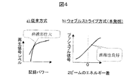
このようにしてウォブル状に情報を記録することにより、多値化記録が容易になる。すなわち、従来例における記録ドメイン面積を変化させる事による多値記録方式においては、図4(a)に示したように、記録パワーと、その記録パワーで形成された記録ドメインからの再生光信号の強度との関係が非線形となり、多値記録のための記録パワー制御が難しい。これに対して、本願発明の再生信号においては、複数のエネルギービームのパワーを相補的に変化させた際の変化量と、ウォブル量検出信号(プッシュプル信号など)とがリニアな関係となる。従って、多値化に必要な所定の再生信号を得る為の記録制御がきわめて容易になる。この為、本方式は特に多値化に有効である。また,本方式においては,ウォブル状記録マークを形成する際に,中心位置から左右に任意の量だけウォブルさせることが可能であり,ウォブル量に関して何ら制限するものがない。このため,任意のアナログレベルに対応した信号(例えば正弦波状に変調された信号)を忠実に再現したウォブル状記録マークをディスク媒体状に形成することが可能となるため,アナログ記録を含めた任意の多値記録方式の適用が可能となる。
【0010】
また,光スポット総和エネルギーが最大になる位置の移動に際しては,レンズなどを物理的に移動させる必要がないため,超高速の移動が容易である。(原理的には光速を越える移動も可能である。この場合,光速度を越えると言っても,実際に物質やエネルギーの移動自体は光速を越えるわけではなく,単にエネルギーが最大になる位置が見かけ上移動するだけであって,アインシュタインの特殊相対性原理に反するするわけではない。これは,異なる2点間で光を交互に点滅させた場合,人間の目には光が1点から別の点に一瞬で移動したように見えるが,実際に光源自体が移動した訳ではないのと同様である。)
また、複数のエネルギービームのパワーを相補的に変化させる際にエネルギービームの総エネルギーをほぼ一定に保つ事により、熱的に安定した記録ドメインをストライプ状に形成する事が出来る。この場合は、記録ドメインのストライプ形状の乱れが少なくノイズの少ない再生信号が得られて、更に多値化のレベル(多値化の数)を上げる事が出来て記録密度が上げられるという効果がある。
【0011】
なお、本願発明完成後に、公知例調査を行ったところ、複数の光ビームを形成する公知技術を見いだした。この公知技術は、特開昭53−3202号に記載されており、これには、複数の光ビームの中心軸を記録トラックに対して直交方向に所定間隔離間させて、光ビームを合成させ、頂上部が平坦でかつ大きな勾配を有する光強度分布の光ビームを得るものである。しかし、この公知例は、複数の光スポットを同期的に変調させるものでも、ウォブルさせるものでもない。
【0012】
【発明の実施の形態】
(実施例1)
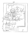
図1は本発明の一実施例であり、本発明の作用を示した説明図となっている。図1において記録媒体中の記録面7に記録ドメイン6を記録データ列方向(トラック方向)に形成する事により情報を記録する。この記録ドメイン6は、クロストラック方向(トラック直交方向)に複数存在する。すなわち,複数の記録トラックから構成される。記録面7は、色素、相変化材料、金属、半導体、光学結晶、光磁気記録材料,その他の光学的な性質の変化をエネルギービーム3及びエネルギービーム4を照射することにより引き起こされる物質である。集光レンズ5によりエネルギービーム3及びエネルギービーム4は集光される。エネルギービーム3と記録面7の交差領域1と、エネルギービーム4と記録面7の交差領域2とは、互いに近接した場所に存在しているが、完全に重なっている事は無く、重なり領域を有する有意にずれた位置にある。そのずれる方向に関しては、情報列方向ではなく、情報列方向から有意な角度にてずれている必要が有る。図1の場合は、領域1と領域2とは同一の大きさの円であり、円の直径の20%程度だけクロストラック方向に領域1と領域2とがずれた例を示している。
【0013】
図1のケース Aは、領域1及び領域2を含んだクロストラック方向に、記録面7上のエネルギービーム3及びエネルギービーム4の強度の分布を示したものである。この場合は、エネルギービーム3とエネルギービーム4との強度は同一である。記録面7上のエネルギービーム3の強度の分布は分布11であり、記録面7上のエネルギービーム4の強度の分布は分布12であり、エネルギービーム3とエネルギービーム4のトータルの強度が分布10となっている
図1のケース Bは、領域1及び領域2を含んだクロストラック方向に、記録面7上のエネルギービーム3及びエネルギービーム4の強度の分布を示したものである。この場合は、エネルギービーム4はエネルギービーム3よりも強度が高い。記録面7上のエネルギービーム3の強度の分布は分布21であり、記録面7上のエネルギービーム4の強度の分布は分布22であり、エネルギービーム3とエネルギービーム4のトータルの強度が分布20となっている。この場合、分布20の大きさ(ピーク値ないし全体積分値)は分布10と略同一となっている。また、分布20のピークのクロストラック方向位置は、分布10のピークのクロストラック方向位置に比べ、図面上で左側にズレている。
【0014】
図1のケース Cは、領域1及び領域2を含んだクロストラック方向に、記録面7上のエネルギービーム3及びエネルギービーム4の強度の分布を示したものである。この場合は、エネルギービーム3はエネルギービーム4よりも強度が高い。記録面7上のエネルギービーム3の強度の分布は分布31であり、記録面7上のエネルギービーム4の強度の分布は分布32であり、エネルギービーム3とエネルギービーム4のトータルの強度が分布30となっている。この場合、分布30の大きさ(ピーク値ないし全体積分値)は分布10と略同一となっている。また、分布30のピークのクロストラック方向位置は、分布10のピークのクロストラック方向位置に比べ、図面上で右側にズレている。
【0015】
ケース A、ケース B、ケース Cを適当な順番にて変化させる事によって、記録面7に与えるエネルギー分布を分布10、分布20、分布30の如く高速に変化させることが可能である。これを実施しながら、エネルギービーム3及びエネルギービーム4に対して記録面7を記録情報列方向に相対移動させる事によって、記録ドメイン6を高速に蛇行させることが可能である。また、分布10、分布20、分布30の大きさ(ピーク値ないし全体積分値)を略同一としながらそれぞれの分布のピーク位置を変化させることが可能であり、常に熱的に安定した記録を記録面7に対して行う事が出来る。このような熱安定的な記録ドメイン7(記録マーク)の書き込みは、記録ドメイン7の太さの均一化、ドメインウォール(マーク周辺部)の平滑化を生じさせる為、ドメイン(マーク)形状の常に揃った安定した情報の書き込みが出来るという効果がある。
【0016】
また、エネルギービーム3とエネルギービーム4の強度の相違をより細分化してより沢山のケースを設けたりする事が可能である。このような場合記録情報の多値化が可能となり、より多くの情報を記録する事が可能となる効果がある。本実施例では,この多値化により高密度の情報の記録を行った。
【0017】
エネルギービーム3とエネルギービーム4が可干渉性を有している場合、領域1と領域2との重なっている部分で干渉縞が発生する事が有る。このような干渉縞を除去する必要が有る場合、例えばエネルギービーム3とエネルギービーム4の波の振動方向を略直行させるかあるいは右回りと左回りの円偏光を照射するのが良い。この干渉縞の除去を行った場合、分布10、分布20、分布30の分布形状が常に安定し、常に安定した記録ドメインが形成できて信頼性が向上するという効果がある。
【0018】
以下本実施例の具体構成を示す。図5は本実施例の2ビーム照射光学系を示したものである。2つのビームの左右の円偏光として照射している。2つの半導体レーザ光源611及び612から発せられて光は直線偏光であり,回折格子641及び642は通った後,後1/2波長版651により,一方の光の偏光面を90度回転させる。2つの光は偏光ビームスプリッタ(PBS)66でほぼ1つの光束に合成される。偏光ビームスプリッタ(PBS)66はレーザ612から発せられた偏光方向の光は反射し,波長版651によって回転させられた偏光方向の光は素通りさせる性質がある。ここで,ほぼ一つと表現したのは,2つの光束の角度は微妙に異なっているためである。合成された光は,1/4波長版69によって円偏光に変換されるが,このとき,光源611側から来た光と612側から来た光の偏光面は互いに直交している為,左右の異なる円偏光にそれぞれ変換される。その後,立ち上げミラー67対物レンズ68を得て媒体7上に照射され,2つの円偏光スポットを形成する。この円偏光スポットは,前述の角度の微妙なずれの分だけ位置が微妙にずれている。2つの光の重なりの部分においても,偏光状態が異なるため,光が干渉してスポット形状が変形する恐れはない。光は記録媒体7で反射させられるが反射すると,鏡の効果により右回り円偏光は左回りに,左回り円偏光は右回りに互いに変換されるため,反射光は1/4波長板69を通ると元の偏光とは直交する偏光状態となり,結果として偏光ビームスプリッタ(PBS)で元の光源とは互いに異なる方向へ戻されることとなる。戻った光は回折格子で多分割検出器621及び622に導かれ,再生信号,プッシュプル信号に加え,自動フォーカスやトラッキングのためのサーボ信号が生成される。本実施例においては,2つのスポットの位置関係を調整する際には,1/4波長板69本来の位置から若干回転させた位置で行った。このようにすることにより,2つのビームからの戻り光が完全に分離はしないで,同一のディテクタに入るようになる。したがって,ディテクタ上でビームの位置を調整することで,2ビームの位置正確に合わせることが可能となる。実際にはプッシュプル検出器上で2つのビームを交互に点滅させたときに得られるプッシュプル信号の振幅から,2つのスポットの位置ずれ量を算出することができるため,本実施例ではこのことを利用して自動調整を行った。
【0019】
本実施例では,光源して,波長405nmの半導体レーザを2つ用いており,開口比(NA)0.85の対物レンズで,記録媒体上に集光して,2つの隣接する光スポット対を形成している。各スポットの直径は約450nmであり,スポット間隔はスポット系の20%に相当する90nmであり,2つのスポットはトラック垂直方向に90nmだけずれている。したがって,残りの360nmは重なっている。 ここで,本実施例においては,記録信号として,直交振幅変調方式(QAM)を用いた。まず始めに記録データは,2系列のN値デジタル情報(IK,QK;K=0,1,2....)に変換される。ここで情報はN値であるので,0〜N-1までの値を取るものとする。記録信号は上記2系列のデジタル情報列にしたがって,
S(t)=Σ{ 2×IK −(N−1)}・Sin(2πt/T)・w(t−K・T)
+ Σ{ 2×QK −(N−1)}・Cos(2πt/T)・w(t−K・T)
と変調される。
【0020】
ここで,ΣはKについての和をとるものとし,Tはシンボル長,wは窓関数である。この例ではwとして w(t)=1(0≦t<T),w(t)=0(t<0,T≦t)となる,矩形窓関数を用いた。 本実施例ではN=6とした。各系列は6値すなわち全体として1シンボルあたり36値となる。前述の記録データから2系列の6値デジタル情報への変換は,5ビットの記録データを36値すなわち1シンボルに対応させる方式とした。5ビットは32値であるので,残りの4値は,記録データへの位相同期と自動ゲイン補正に利用した。上記S(t)にしたがって,光ビーム中心位置を変調して,光記録媒体7上にウォブル状マークを形成した。
【0021】
本実施例ではT=35nsとし,線速度10m/秒で記録を行った。したがって,記録媒体上ではでは1シンボルの長さは380nmに相当する。したがって,ビット長は75nmとなる。また,トラックピッチは280nmとした。形成されたウォブル状記録マークの幅は約120nmでウォブル振幅は60nmppである。
【0022】
情報の再生においては、エネルギービーム3ないしエネルギービーム4の片方ないし双方を、ケース A〜ケース Cの場合よりも低エネルギーの状態にして記録面7に照射し、反射光(ないしは透過光)のクロストラック方向の分布変化を検出することで、記録ドメイン6の蛇行を検出する事が可能であり、これによって情報を再生する。 検出には2種の方法がある(図6)。2ビームを同時に照射し,その各々反射光の光量の差を信号とするビーム差動方式(a)と一つのビームの反射光の光量の左右の差分を信号とする回折プッシュプル法(b)がある。回折プッシュプル法はウォブル信号やトラッキング信号を検出するのに従来から用いられている方式であるが,記録マークが光学的位相差を発生させないようないわゆる濃淡マークの場合には反射光に位相差が生じないため使用できない。そこで本実施例においては,ビーム差動方式(a)を用いた。
【0023】
再生信号を図8(a)に示す。この再生信号は再生光スポットの分解能の影響で,高周波の信号強度が低下しているため,再生系の周波数特性を補償する波形等化処理を行い,その後,復調を行う。
この例では波形等化処理は再生時にのみ行っているが,記録時にも事前等化を行ってもよく,その場合,記録課程で生じる若干の非線形性を含めて補正しておくことができ,より高密度な記録に適する。
【0024】
図8(a)の再生信号を復調するには,2種の参照波形:Sin(2πt/T),Cos(2πt/T)を上記再生信号に乗算し,Tの時刻分毎積分したときの積分出力値を,上記2系列に対応して縦軸,横軸として直交座標にプロットすると図8(c)のような結果が得られる。この結果から,36値の情報が再生されていることが分かる。図8(b)は波形等化処理を行わなかった際のもので,信号が分離できていない。なお、以上では分布10、分布20、分布30の大きさが略同一である場合を想定した説明となっている。これに対し、分布10、分布20、分布30の大きさを故意に変化させる場合がある。この変化により、記録ドメイン6の幅を変化させる事が可能である。または、記録ドメイン6を記録しない部分を形成する事が可能である。このような記録ドメイン6の有り無しや幅の変化は、記録ドメイン6の蛇行に対して同期をかける信号として用いたり、或いは記録ドメインに対する付加的情報(例えばアドレス情報や著作権保護の為のセキュリティー情報など)を記録する為に用いたりする事が有る。このようなことをする事により、記録されたデータの保全性やアクセッシビリティを向上させる事が可能となる効果がある。実際,図8(a)の再生信号を復調する際には,前述のように参照波を生成して乗算する必要があるが,この参照波の位相と周波数は再生信号と完全に同期が取れている必要が有る。そこで本実施例においては,220Tに一回の割合で,記録マークの幅を矩形上に太くした同期マーク部761を設けた(図7)。この太くした部分は,通常のデータ部分のマーク762とは幅が異なる為,再生時にその部分だけ反射率が変ることになる。このため,この反射率の異なる同期マーク部761は通常のウォブルのみの部分762と容易に判別することができる。この同期マークは220Tの周期で現れる為,参照信号を220分周して得られるパルスの位相を同期マークと合わせることにより,参照信号の位相と周波数を再生信号に対して同期することが容易になる。これは言いかえれば,同期マークの検出信号220逓倍して参照信号(クロック)を生成することに相当する。
【0025】
以上では、ケース A〜ケース Cの3ケースで説明したが、ケース Bとケース Cの2ケースのみで2値的に変調するのも可能である。この場合は、エネルギービームの強度変化制御が容易になりシステム簡素化による信頼性向上の効果がある。このような2値変調の部分では前述の高密度化の効果は得られないが,信頼性が高いため,記録システム上で特に高い信頼性が要求されるファイル管理情報や記録領域管理情報などのシステム情報の記録部に適する。本実施例では,ディスクの最内周と最外周の約0.5%の領域をこの2値記録方式で記録しており,ファイル管理・欠陥管理および記録領域管理情報の記録に利用している。本実施例では直径120mmディスクの1面に約50GBの容量が記録できる。0.5%は250MBに相当し,管理情報領域としては充分である。
(実施例2)
図1の実施例に於けるトラッキングの方法について図2にて述べる。図2は図1における記録面7及び記録ドメイン6を部分拡大した説明図である。図2において、記録面7には記録ドメイン6が形成されている。トラッキングの方法の一例としてここでは、トラッキング方法A、及びトラッキング方法Bについて述べる。
【0026】
トラッキング方法Aを図2aで説明する。図2aの記録面7の断面は断面40の如く部分的な凹凸ストライプ41が形成されている。このような溝(乃至は出っ張り)に対してエネルギービーム1およびエネルギービーム2を照射し、この反射光ないし透過光を検出する。この検出の結果からクロストラック方向の反射光ないし透過光強度の分布の変化(プッシュプル信号)を検出して、これを常に一定となるようにエネルギービーム1およびエネルギービーム2のクロストラック方向の位置を調整することにより、常に予期された位置に記録ドメイン6を形成する事が出来る。なお、凹凸ストライプ41をクロストラック方向に蛇行させたり、クロストラック方向の幅を変化させることなどにより、凹凸ストライプ41上の物理的な位置を示すアドレス情報を凹凸ストライプ41に持たせることが出来る。このような場合、エネルギービームの位置決めが容易になるという効果が有る。
【0027】
次いで、トラッキング方法Bを図2bで説明する。図2bの記録面7には予め千鳥マーク51および千鳥マーク52が形成されている。ただし、千鳥マーク51と千鳥マーク52とはクロストラック方向にずれた位置にある。エネルギービーム1およびエネルギービーム2が千鳥マーク51および千鳥マーク52を通過する際のプッシュプル信号乃至は透過光ないし反射光の総光量の変化を検出する事によりトラッキング信号のサンプルサーボ信号を形成して、これが常に一定の値となるようにする事により、常に予期された位置に記録ドメイン6を形成する事が出来る。なお、千鳥マーク51や千鳥マーク52の形成されている部分には記録ドメイン6を形成しない事が考えられる。これは千鳥マーク51や千鳥マーク52が常に定期的な周期で現れるようにこれらのマークを記録面上に形成し、これら一定の周期の一定の期間のみは記録を行わない事により達成できる。このようにした場合、千鳥マーク51や千鳥マーク52の読み出しの信頼性が向上するという効果が有る。なお、千鳥マーク51や千鳥マーク52のマーク列に一定のパターンを付与し、これらのマークに物理的な位置をあらわすのアドレス情報をもたせる事が有る。このようにした場合、エネルギービームの位置決めが容易になるという効果が有る。なお、千鳥マーク51や千鳥マーク52を予め作り込まれたプリピットの形として形成する事がある。このようにした場合、千鳥マーク51や千鳥マーク52が消去されず、常に正しいサーボ信号が得られて、信頼性が向上するという効果がある。
(実施例3)
図3により、本発明の別な実施例を示す。図3において、筐体108に取りつけられたモーター110の回転軸111にはチャッキング機構112が取りつけられ、チャッキング機構112は記録媒体100を保持している。チャッキング機構112は、即ち記録媒体100の保持機構となっている。また、モーター110、回転軸111、及びチャッキング機構112により、記録媒体100とエネルギービームを相対的に移動させる移動機構を構成している。
【0028】
筐体108にはレール115が取りつけられている。ケース117にはレール115にガイドされるレールガイド116が取りつけられている。また、ケース117には直線ギア119が取り付けられており、直線ギア119には回転ギア120が取りつけられている。筐体108に取りつけられた回転モーター118の回転を回転ギア120に伝えることにより、ケース117はレール115に沿って直線運動する。この直線運動の方向は、記録媒体100の略半径方向となっている。
【0029】
ケース117には磁石121が取りつけられている。また、ケース117には、対物レンズ130を記録媒体100の記録面の略法線方向と、記録媒体100の略半径方向の2つの方向にのみ移動可能とするサスペンション123を介して対物レンズ130が取りつけられている。また、対物レンズ130には磁石121と略対向するようにコイル122が取りつけられている。コイル122に電流を流すことにより、磁力的な効果により、対物レンズ130は記録媒体100の記録面の略法線方向と、記録媒体100の略半径方向の2つの方向に移動することが出来る。レール115、レールガイド116、ケース117、磁石121、サスペンション123、コイル122、対物レンズ130により、エネルギービームを記録媒体100上の所定の位置に位置付ける位置決め機構を構成している。
【0030】
ケース117には、エネルギービーム発生器である半導体レーザ131および半導体レーザ231が取りつけられる。半導体レーザ131から射出したエネルギービームは、コリメートレンズ132により略並行光とされビームスプリッダ233を通過する。半導体レーザ231から射出したエネルギービームは、コリメートレンズ232により略並行光とされビームスプリッダ233で反射される。この際、半導体レーザ131から射出してビームスプリッダ233を通過した光の光軸と、半導体レーザ231から射出してビームスプリッダ233で反射した光の光軸ととが完全に平行で無く、僅かに角度を有するように半導体レーザ131、コリメートレンズ132、半導体レーザ231、コリメートレンズ232、ビームスプリッダ233の位置を調整する。半導体レーザ131および半導体レーザ231を射出したそれぞれの光はビームスプリッダ133を通過し、対物レンズ130を通過して、記録媒体100の記録面に焦点を形成する。この時、半導体レーザ131から射出た光の光軸と、半導体レーザ231から射出した光の光軸ととが僅かに角度を有するため、記録面における焦点スポットは僅かにズレを生じている。このズレは、記録媒体の略半径方向となっている。
【0031】
対物レンズ130から射出した光の一部は記録媒体100で反射され、対物レンズ130を通過し、ビームスプリッダ133で反射され、検出レンズ134で集光され、光検出器135で光強度を検出される。光検出器135は、受光エリアが複数に分割されている。それぞれの受光エリアで検出された光強度はアンプ152で増幅されると共に演算され、対物レンズ130で集光された光スポットと記録媒体100との相対的な位置関係の情報(サーボ信号)と情報読み出し信号とが検出される。サーボ信号はサーボコントローラ151に送られる。また、読み出し信号はウォブル検出回路171を通してデコーダ153に送られる。
【0032】
情報の記録再生装置に記録媒体100が取りつけられ、チャッキング機構112が記録媒体100を固定すると、検出器140が作動し、その信号をシステムコントローラ150に送る。システムコントローラ150はそれを受けて、モーター110を制御して記録媒体100を適切な回転数となるように回転させる。また、システムコントローラ150は、回転モーター118を制御して、ケース117を適切な位置に位置決めする。また、システムコントローラー150は半導体レーザ131および半導体レーザ231を発光させると共に、サーボコントローラ151を動作させて回転モータ118を動作させたりコイル122に電流を流して、対物レンズ130の形成する焦点スポットを記録媒体100の上の所定の位置に位置決めする。ついで、サーボコントローラ151は焦点スポットが記録媒体100上に形成された由の信号をシステムコントローラ150に送る。システムコントローラ150はデコーダ153に指示を与え、読み出される信号をデコードする。読み出されるトラックがコントロールデータゾーンの情報トラックでない場合、システムコントローラ150はサーボコントローラ151に指示を与え、焦点スポットがコントロールデータゾーンの情報トラックに位置決めされるようにする。上記の動作の結果、システムコントローラー150はコントロールデーターゾーンの情報トラックを読み取り、記録や再生に関する媒体の情報を読み出す。
【0033】
入力コネクタ159を介して上位コントローラから情報書き込みの指示及び書き込むべき情報が送られてきた場合、システムコントローラ150はサーボコントローラ151に指示を与えて焦点スポットを記録媒体100の上の適切なトラックに位置決めする。書き込むべき情報はパターン生成回路155に伝えられる。パターン生成回路155は、システムコントローラ150に指示されるセクター内の記録情報配置の方法に沿って、セクター内に記録すべきユーザーデータエリアの情報、ユーザーデータ−エリアに先行して付随すべき記録情報配置(バッファやその他のフィールド)、ユーザーデータエリアに引き続いて付随すべき記録情報配置(バッファやその他のフィールド)をアレンジし、セクター内での記録情報配置のパターン列を完成する。パターン生成回路155は、自ら生成した記録パターンの一つ一つを順次にレーザドライバ回路154に送る。レーザドライバ回路154は、パターン生成回路155から送られてきた書き込むべき記録マークパターンに応じて、半導体レーザ131および半導体レーザ231に注入する電流値を変化させる。この際、半導体レーザ131および半導体レーザ231に注入する電流の和は一定に保ち、夫々のレーザに配分する電流の割合を変化させる。半導体レーザ131および半導体レーザ231の射出光は、対物レンズ136を通して記録媒体100に照射され、これにより記録媒体上に記録ドメインを形成する。記録ドメインの形成の手法については図1にて説明した方法と同様である。
【0034】
入力コネクタ159を介して上位コントローラから情報再生の指示を送ってきた場合、システムコントローラ150はサーボコントローラ151に指示を与えて焦点スポットを記録媒体100の上の適切なトラックに位置決めする。光検出器135で得られた信号はアンプ152により増幅され、ウォブル検出器171およびデコーダ153を通して再生信号がシステムコントローラ150に送られると同時に出力コネクタ158を通して読み出した情報を上位コントローラに送る。
【0035】
以上の構成により常に安定した記録ドメインを形成可能である信頼性の高い情報の記録再生装置が構成できるという効果がある。また、多値化によりより高密度の情報の記録再生装置が構成できるという効果がある。
【0036】
2つのスポット照射する方法として,以上詳述した方法に変えて,出射ビームの方向や角度を変える機能を持ったレーザを用いる方法もある。この場合,光学系の構成や調整が簡単になるが,レーザ自体が複雑になるという欠点もあり,実際には,レーザの作製コストと光学系の調整コストを比較して選択すればよい。いずれにしても,上述した本発明の高密度化の効果は上述と同様にえられる。
【0037】
【発明の効果】
上記構成により、安定した、高い記録密度を達成できる。
【図面の簡単な説明】
【図1】本発明の一実施例であり、本発明の作用を示した説明図。
【図2】図1を部分拡大した説明図である。
【図3】本発明の別な実施例。
【図4】本発明の別な実施例。
【図5】本発明の光ヘッド光学系の実施例。
【図6】本発明の再生方式の説明図。
【図7】本発明の実施例の記録マーク形状を示す図。
【図8】本発明の実施例の再生信号の例。
【符号の説明】
1・・・交差領域
2・・・交差領域
3・・・エネルギービーム
4・・・エネルギービーム
5・・・対物レンズ
6・・・記録ドメイン
7・・・記録面
10・・・分布
11・・・分布
12・・・分布
20・・・分布
21・・・分布
22・・・分布
30・・・分布
31・・・分布
32・・・分布
40・・・断面
41・・・凹凸ストライプ
51・・・千鳥マーク
52・・・千鳥マーク
100・・・記録媒体
108・・・筐体
110・・・モーター
111・・・回転軸
112・・・チャッキング機構
115・・・レール
116・・・レールガイド
117・・・ケース
118・・・回転モータ
118・・・回転モーター
119・・・直線ギア
120・・・回転ギア
121・・・磁石
122・・・コイル
123・・・サスペンション
130・・・対物レンズ
131・・・半導体レーザ
132・・・コリメートレンズ
133・・・ビームスプリッダ
134・・・検出レンズ
135・・・光検出器
136・・・対物レンズ
140・・・検出器
150・・・システムコントローラ
150・・・システムコントローラー
151・・・サーボコントローラ
152・・・アンプ
153・・・デコーダ
154・・・レーザドライバ回路
155・・・パターン生成回路
158・・・出力コネクタ
159・・・入力コネクタ
171・・・ウォブル検出回路
231・・・半導体レーザ
232・・・コリメートレンズ
233・・・ビームスプリッダ
66・・・偏光ビームスプリッタ(PBS)
67・・・立ち上げミラー
68・・・対物レンズ
69・・・1/4波長板
611,612・・・レーザ
621,622・・・分割検出器
631,632・・・コリメータレンズ
641,642・・・回折格子
651・・・1/2波長板。[0001]
BACKGROUND OF THE INVENTION
The present invention relates to an information recording method, an information reproducing method, and a recording / reproducing apparatus using an information recording medium capable of recording information by irradiation with an energy beam.
[0002]
[Prior art]
Conventionally, a single laser beam is irradiated onto a recording medium to change the laser beam intensity, or to change the applied magnetic field to the recording area while keeping the laser beam intensity constant, thereby recording marks and domains. Was forming.
[0003]
On the other hand, multilevel recording for increasing the density is known. This multilevel recording is described in Technical Digest of International Symposium on Optical Memory 2001, 2001, p238, The First Dye Media for Multilevel Recording System, Arioka et al, and the same document p240, Advanced Gray Scale Recording on Phase Change Optical Disks. As described above, the reproduction signal is multi-valued mainly by changing the area of the recording mark and the domain.
[0004]
Regarding the multi-level reproduction signal, it is known that Proceeding of Optical Data Storage 2000, SPIE Vol. 4090, 2000 has recorded information in the wobbles of the grooves to increase the multi-level reproduction signal. It has been. Note that this is a ROM, which is a mastered medium and not related to recording.
[0005]
[Problems to be solved by the invention]
In the above-described method of irradiating the medium with a single beam, if the recording density is improved, the distance between the recording domains is shortened to be within the thermal diffusion distance at the time of recording. Therefore, there is a limit to increasing the density.
[0006]
In the multi-value recording method for increasing the density, if the size of the recording domain is reduced for the purpose of increasing the density, the stability of recording domain formation gradually decreases, which is also limited to the higher density. There is.
[0007]
An object of the present application is to achieve high-density recording stably.
[0008]
[Means for Solving the Problems]
The above object is achieved by the following configuration. That is, the plurality of light spots are synchronously modulated so that the plurality of light spots have overlapping areas on the medium, and the recording medium is irradiated with the light spots. Here, since the profile of the total energy of the plurality of light spots is modulated when the light intensities of the plurality of light spots are synchronously modulated, for example, the position where the total energy is maximum on the optical recording medium. It can be moved arbitrarily. Therefore, by moving the maximum total energy point of the light spot in the track vertical direction, information can be recorded in a wobble shape as a result.
[0009]
By recording information in a wobble form in this way, multi-value recording becomes easy. That is, in the multilevel recording method by changing the recording domain area in the conventional example, as shown in FIG. 4A, the recording power and the reproduction optical signal from the recording domain formed by the recording power are recorded. The relationship with intensity becomes non-linear, and it is difficult to control recording power for multi-level recording. On the other hand, in the reproduction signal of the present invention, the amount of change when the powers of a plurality of energy beams are changed complementarily and the wobble amount detection signal (such as a push-pull signal) have a linear relationship. Therefore, recording control for obtaining a predetermined reproduction signal necessary for multi-level recording becomes extremely easy. For this reason, this method is particularly effective for multi-value processing. In this method, when forming a wobble-shaped recording mark, it is possible to wobble an arbitrary amount to the left and right from the center position, and there is no limitation on the wobble amount. For this reason, a wobbled recording mark faithfully reproducing a signal corresponding to an arbitrary analog level (for example, a signal modulated in a sine wave shape) can be formed on a disk medium, so that an arbitrary recording including analog recording can be performed. The multi-value recording method can be applied.
[0010]
Moreover, when moving the position where the total energy of the light spot is maximized, it is not necessary to physically move the lens or the like. (In principle, movement beyond the speed of light is possible. In this case, even if the speed of light is exceeded, the movement of the substance or energy does not actually exceed the speed of light. It moves only in appearance, and does not violate Einstein's principle of special relativity, because light blinks alternately between two different points from one point to the other. (It seems that the light source itself has not actually moved.
In addition, when the power of the plurality of energy beams is changed in a complementary manner, by keeping the total energy of the energy beams substantially constant, a thermally stable recording domain can be formed in a stripe shape. In this case, there is an effect that the recording domain stripe shape is less disturbed and a reproduced signal with less noise is obtained, and the level of multi-value (number of multi-values) can be further increased to increase the recording density. is there.
[0011]
After completion of the present invention, a known example was investigated, and a known technique for forming a plurality of light beams was found. This known technique is described in Japanese Patent Application Laid-Open No. 53-3202. In this technique, the central axes of a plurality of light beams are spaced apart from each other in a direction perpendicular to the recording track to synthesize the light beams, A light beam having a light intensity distribution having a flat top and a large gradient is obtained. However, this known example does not modulate or wobble a plurality of light spots synchronously.
[0012]
DETAILED DESCRIPTION OF THE INVENTION
Example 1
FIG. 1 shows an embodiment of the present invention and is an explanatory diagram showing the operation of the present invention. In FIG. 1, information is recorded by forming a
[0013]
Case A in FIG. 1 shows the intensity distribution of the
Case B in FIG. 1 shows the intensity distribution of the
[0014]
Case C in FIG. 1 shows the intensity distribution of the
[0015]
By changing Case A, Case B, and Case C in an appropriate order, the energy distribution given to the
[0016]
Further, it is possible to subdivide the difference in intensity between the
[0017]
When the
[0018]
The specific configuration of the present embodiment will be described below. FIG. 5 shows the two-beam irradiation optical system of this embodiment. The two beams are irradiated as left and right circularly polarized light. The light emitted from the two semiconductor
[0019]
In this embodiment, two semiconductor lasers having a wavelength of 405 nm are used as light sources, and two adjacent light spot pairs are formed by focusing on a recording medium with an objective lens having an aperture ratio (NA) of 0.85. is doing. The diameter of each spot is about 450 nm, the spot interval is 90 nm corresponding to 20% of the spot system, and the two spots are shifted by 90 nm in the track vertical direction. Therefore, the remaining 360nm overlaps. Here, in this embodiment, a quadrature amplitude modulation method (QAM) is used as the recording signal. First, the recorded data is two series of N-value digital information (I K , Q K ; K = 0,1,2, ...). Here, since the information is an N value, a value from 0 to N-1 is assumed. The recording signal follows the above two series of digital information sequences.
S (t) = Σ {2 × I K − (N−1)} · Sin (2πt / T) · w (t−K · T)
+ Σ {2 × Q K − (N−1)} · Cos (2πt / T) · w (t−K · T)
And modulated.
[0020]
Here, Σ is the sum of K, T is the symbol length, and w is the window function. In this example, a rectangular window function in which w (t) = 1 (0 ≦ t <T) and w (t) = 0 (t <0, T ≦ t) is used as w. In this embodiment, N = 6. Each series has 6 values, that is, 36 values per symbol as a whole. The conversion from the above-mentioned recording data to 2-series 6-value digital information is based on a system in which 5 bits of recording data correspond to 36 values, that is, one symbol. Since 5 bits are 32 values, the remaining 4 values were used for phase synchronization to the recorded data and automatic gain correction. According to S (t), the center position of the light beam was modulated to form a wobble mark on the
[0021]
In this embodiment, T = 35 ns and recording was performed at a linear velocity of 10 m / sec. Therefore, the length of one symbol on the recording medium corresponds to 380 nm. Therefore, the bit length is 75 nm. The track pitch was 280 nm. The width of the formed wobbled recording mark is about 120 nm and the wobble amplitude is 60 nmpp.
[0022]
In the reproduction of information, one or both of the
[0023]
The reproduction signal is shown in FIG. Since the reproduction signal has a high-frequency signal intensity lowered due to the effect of the resolution of the reproduction light spot, waveform equalization processing is performed to compensate for the frequency characteristics of the reproduction system, and then demodulation is performed.
In this example, waveform equalization processing is performed only during playback, but pre-equalization may also be performed during recording, in which case it can be corrected including some non-linearity that occurs during the recording process. Suitable for higher density recording.
[0024]
In order to demodulate the reproduction signal of FIG. 8A, when the reproduction signal is multiplied by two reference waveforms: Sin (2πt / T) and Cos (2πt / T) and integrated every T times. When the integrated output values are plotted on the orthogonal coordinates as the vertical axis and the horizontal axis corresponding to the above two series, the result shown in FIG. 8C is obtained. From this result, it can be seen that 36-value information is reproduced. FIG. 8B shows the case where the waveform equalization processing is not performed, and the signals cannot be separated. In the above description, it is assumed that the sizes of the
[0025]
In the above, the case A to the case C have been described, but it is also possible to perform binary modulation only in the case B and the case C. In this case, the intensity change control of the energy beam becomes easy, and there is an effect of improving reliability by simplifying the system. Such binary modulation does not provide the above-mentioned high density effect, but because of its high reliability, file management information, recording area management information, etc. that require particularly high reliability on the recording system. Suitable for system information recording part. In this embodiment, an area of about 0.5% of the innermost circumference and the outermost circumference of the disk is recorded by this binary recording method, and is used for file management / defect management and recording area management information recording. In this embodiment, a capacity of about 50 GB can be recorded on one side of a 120 mm diameter disk. 0.5% is equivalent to 250MB, which is sufficient as a management information area.
(Example 2)
A tracking method in the embodiment of FIG. 1 will be described with reference to FIG. FIG. 2 is an explanatory diagram in which the
[0026]
Tracking method A is illustrated in FIG. In the cross section of the
[0027]
Next, the tracking method B will be described with reference to FIG. A
Example 3
FIG. 3 shows another embodiment of the present invention. In FIG. 3, a chucking mechanism 112 is attached to the rotation shaft 111 of the
[0028]
A
[0029]
A
[0030]
A
[0031]
Part of the light emitted from the
[0032]
When the
[0033]
When an instruction to write information and information to be written are sent from the host controller via the
[0034]
When an instruction for reproducing information is sent from the host controller via the
[0035]
With the above configuration, there is an effect that a highly reliable information recording / reproducing apparatus that can always form a stable recording domain can be configured. In addition, there is an effect that a higher density information recording / reproducing apparatus can be configured by multi-leveling.
[0036]
As a method of irradiating two spots, there is a method using a laser having a function of changing the direction and angle of the outgoing beam, instead of the method described in detail above. In this case, the configuration and adjustment of the optical system are simplified, but there is also a drawback that the laser itself is complicated. In practice, it is only necessary to select the laser fabrication cost and the optical system adjustment cost. In any case, the above-described effect of increasing the density of the present invention can be obtained in the same manner as described above.
[0037]
【The invention's effect】
With the above configuration, a stable and high recording density can be achieved.
[Brief description of the drawings]
FIG. 1 is an explanatory view showing an operation of the present invention, which is an embodiment of the present invention.
FIG. 2 is a partially enlarged explanatory view of FIG. 1;
FIG. 3 shows another embodiment of the present invention.
FIG. 4 shows another embodiment of the present invention.
FIG. 5 shows an embodiment of an optical head optical system according to the present invention.
FIG. 6 is an explanatory diagram of a playback method according to the present invention.
FIG. 7 is a diagram showing a recording mark shape according to an embodiment of the present invention.
FIG. 8 shows an example of a reproduction signal according to the embodiment of the present invention.
[Explanation of symbols]
1 ... Intersection area
2 ... Intersection area
3. Energy beam
4 ... Energy beam
5 ... Objective lens
6 ... Recording domain
7 ... Recording surface
10 ... Distribution
11 ... Distribution
12 ... Distribution
20 ... Distribution
21 ... Distribution
22 ... Distribution
30 ... Distribution
31 ... Distribution
32 ... Distribution
40 cross section
41 ... Uneven stripe
51 ... Chidori mark
52 ... Chidori mark
100 ... Recording medium
108 ... Case
110 ... Motor
111 ... Rotating shaft
112 ... Chucking mechanism
115 ... Rail
116 ... Rail guide
117 ... Case
118 ... Rotary motor
118 ... Rotary motor
119 ... Linear gear
120 ... Rotating gear
121 ... Magnet
122 ... Coil
123 ... Suspension
130 ... Objective lens
131: Semiconductor laser
132 ... Collimating lens
133: Beam splitter
134... Detection lens
135... Photodetector
136... Objective lens
140 ... Detector
150 ... System controller
150 ... System controller
151 ... Servo controller
152 ... Amplifier
153: Decoder
154 ... Laser driver circuit
155... Pattern generation circuit
158 ... Output connector
159 ... Input connector
171 ... Wobble detection circuit
231 ... Semiconductor laser
232 ... Collimating lens
233 ... Beam splitter
66 ... Polarizing beam splitter (PBS)
67 ... Launch mirror
68 ... Objective lens
69 ... 1/4 wavelength plate
611, 612 ... Laser
621, 622 ... Split detector
631,632 ... Collimator lens
641,642 ... Diffraction grating
651... Half-wave plate.
Claims (6)
第1の光スポットと第2の光スポットを重なり領域を有するように形成し、前記第1の光スポットと前記第2の光スポットの光強度を同期的に変調させながら、前記第1と第2の光スポットを前記媒体に連続的に照射して、トラック中心位置から左右に任意の量だけウオブルした途切れのないウオブルを形成し、前記第 1 の光スポットと前記第2の光スポットの光強度を相補的に変化させた際の変化量と、ウオブル検出信号とがリニアな関係となるように、情報を多値で記録することを特徴とする情報の記録方法。An information recording method for recording information by irradiating a medium with light to form a recording area,
The first light spot and the second light spot are formed so as to have an overlapping region, and the first and second light spots are synchronously modulated while the light intensity of the first light spot and the second light spot is synchronously modulated. The light beam of the first light spot and the second light spot is formed by continuously irradiating the medium with two light spots to form a continuous wobble that is wobbled by an arbitrary amount to the left and right from the track center position. An information recording method, wherein information is recorded in multiple values so that a change amount when the intensity is changed in a complementary manner and a wobble detection signal have a linear relationship .
前記媒体に、複数の光スポットを重なり領域を有するように連続的に照射する手段と、
前記複数の光スポットのパワーレベルを調整する調整手段と、
前記複数の光スポットそれぞれの位置を調整する調整手段と、
前記複数の光スポットそれぞれのパワーレベルを、同期して変調させる変調手段と、
前記媒体に対して、相対的に前記照射手段を移動させる手段とを有し、
前記変調手段により、前記媒体のトラック中心位置から左右に任意の量だけウオブルした途切れのないウオブルを形成し、前記複数の光スポットのパワーレベルを相補的に変化させた際の変化量と、ウオブル検出信号とがリニアな関係となるように、情報を多値で記録することを特徴とする情報記録装置。An information recording apparatus for recording information on a medium,
Means for continuously irradiating the medium with a plurality of light spots so as to have overlapping regions;
Adjusting means for adjusting the power level of the plurality of light spots;
Adjusting means for adjusting the position of each of the plurality of light spots;
Modulation means for synchronously modulating the power level of each of the plurality of light spots;
Means for moving the irradiation means relative to the medium;
The modulation means forms an uninterrupted wobble that is wobbled by an arbitrary amount to the left and right from the track center position of the medium, and the amount of change when the power level of the plurality of light spots is changed complementarily, An information recording apparatus for recording information in multiple values so that the detection signal has a linear relationship.
Priority Applications (3)
| Application Number | Priority Date | Filing Date | Title |
|---|---|---|---|
| JP2002225486A JP3855876B2 (en) | 2002-08-02 | 2002-08-02 | Information recording method, reproducing method, and recording apparatus |
| CNB031368174A CN1311431C (en) | 2002-08-02 | 2003-05-15 | System and method for recording and replaying information |
| US10/464,742 US7236433B2 (en) | 2002-08-02 | 2003-06-19 | System and method of recording and reproducing information |
Applications Claiming Priority (1)
| Application Number | Priority Date | Filing Date | Title |
|---|---|---|---|
| JP2002225486A JP3855876B2 (en) | 2002-08-02 | 2002-08-02 | Information recording method, reproducing method, and recording apparatus |
Publications (3)
| Publication Number | Publication Date |
|---|---|
| JP2004070992A JP2004070992A (en) | 2004-03-04 |
| JP2004070992A5 JP2004070992A5 (en) | 2005-08-11 |
| JP3855876B2 true JP3855876B2 (en) | 2006-12-13 |
Family
ID=31185049
Family Applications (1)
| Application Number | Title | Priority Date | Filing Date |
|---|---|---|---|
| JP2002225486A Expired - Fee Related JP3855876B2 (en) | 2002-08-02 | 2002-08-02 | Information recording method, reproducing method, and recording apparatus |
Country Status (3)
| Country | Link |
|---|---|
| US (1) | US7236433B2 (en) |
| JP (1) | JP3855876B2 (en) |
| CN (1) | CN1311431C (en) |
Families Citing this family (7)
| Publication number | Priority date | Publication date | Assignee | Title |
|---|---|---|---|---|
| US20110064214A1 (en) * | 2003-09-09 | 2011-03-17 | Ternarylogic Llc | Methods and Apparatus in Alternate Finite Field Based Coders and Decoders |
| US8577026B2 (en) | 2010-12-29 | 2013-11-05 | Ternarylogic Llc | Methods and apparatus in alternate finite field based coders and decoders |
| US7706242B2 (en) * | 2004-02-25 | 2010-04-27 | Ricoh Company, Ltd. | Optical disk, signal generation method, clock signal generation method, and optical disk device |
| US7725779B2 (en) * | 2005-01-25 | 2010-05-25 | Ternarylogic Llc | Multi-valued scrambling and descrambling of digital data on optical disks and other storage media |
| JP2010256081A (en) * | 2009-04-22 | 2010-11-11 | Fujifilm Corp | Optical position detecting apparatus and optical apparatus |
| US8899003B2 (en) | 2011-03-22 | 2014-12-02 | The Procter & Gamble Company | Methods of providing stacks of wet wipes with improved wetness gradients |
| US8817405B1 (en) * | 2013-10-24 | 2014-08-26 | HGST Netherlands B.V. | Magnetic recording disk drive with frequency adjustment for misaligned servo patterns |
Family Cites Families (16)
| Publication number | Priority date | Publication date | Assignee | Title |
|---|---|---|---|---|
| JPS533202A (en) | 1976-06-29 | 1978-01-12 | Mitsubishi Electric Corp | Information reproducer |
| JPS63214919A (en) | 1987-03-03 | 1988-09-07 | Hitachi Maxell Ltd | Optical disk and its reproducing method |
| JPH0253223A (en) | 1988-08-15 | 1990-02-22 | Pioneer Electron Corp | Optical recording and reproducing method |
| JP2846342B2 (en) * | 1989-06-07 | 1999-01-13 | 株式会社日立製作所 | High density optical reproduction device |
| JPH05314491A (en) * | 1992-02-14 | 1993-11-26 | Sony Corp | Data recording medium and data recording and reproducing apparatus |
| JP3307081B2 (en) | 1994-04-27 | 2002-07-24 | 日本ビクター株式会社 | Optical disc master manufacturing method |
| JP3150850B2 (en) * | 1994-07-08 | 2001-03-26 | シャープ株式会社 | Manufacturing method of magneto-optical disk master |
| US5530688A (en) * | 1994-10-31 | 1996-06-25 | International Business Machines Corporation | Optical disk recording device using two modulated laser beams for recording information data |
| GB2300749A (en) * | 1995-05-06 | 1996-11-13 | Thomson Multimedia Sa | A multiple beam optical disk system |
| JPH08315368A (en) * | 1995-05-19 | 1996-11-29 | Victor Co Of Japan Ltd | Optical recording and reproducing method, optical recording and reproducing device and recording medium |
| MY118249A (en) * | 1996-08-30 | 2004-09-30 | Sony Corp | Optical pickup device and disk player apparatus |
| US6310851B1 (en) * | 1997-01-21 | 2001-10-30 | Sony Corporation | Frequency demodulating circuit, optical disk apparatus thereof and preformating device |
| JP3809715B2 (en) * | 1997-10-28 | 2006-08-16 | ソニー株式会社 | Optical information recording medium, optical information recording method, and optical information recording apparatus |
| JP3530735B2 (en) * | 1998-01-29 | 2004-05-24 | パイオニア株式会社 | Optical information reproducing device |
| US6046970A (en) * | 1998-02-13 | 2000-04-04 | International Business Machines Corporation | System for creating, reading and writing on rotatable storage media, an apparatus for determining laser aging characteristics |
| US6275458B1 (en) * | 1999-02-18 | 2001-08-14 | Terrence L. Wong | Method and apparatus for reading and writing a multi-level signal from an optical disc |
-
2002
- 2002-08-02 JP JP2002225486A patent/JP3855876B2/en not_active Expired - Fee Related
-
2003
- 2003-05-15 CN CNB031368174A patent/CN1311431C/en not_active Expired - Fee Related
- 2003-06-19 US US10/464,742 patent/US7236433B2/en not_active Expired - Fee Related
Also Published As
| Publication number | Publication date |
|---|---|
| US20040022158A1 (en) | 2004-02-05 |
| US7236433B2 (en) | 2007-06-26 |
| JP2004070992A (en) | 2004-03-04 |
| CN1474386A (en) | 2004-02-11 |
| CN1311431C (en) | 2007-04-18 |
Similar Documents
| Publication | Publication Date | Title |
|---|---|---|
| JP3237982B2 (en) | Optical information recording / reproducing device and optical information recording medium | |
| EP0999544B1 (en) | Optical disk, optical recording/reproducing apparatus and optical recording/reproducing method | |
| US6215758B1 (en) | Recording medium | |
| JP3048945B2 (en) | Information recording / reproducing device | |
| US6538968B1 (en) | Information recording/reproducing apparatus | |
| JP3855876B2 (en) | Information recording method, reproducing method, and recording apparatus | |
| US6646968B1 (en) | Magneto-optical recording apparatus and method including method for presetting optimum recording power of recording apparatus | |
| US6314061B1 (en) | Linear high density magneto-optical recording apparatus | |
| JPH06208739A (en) | Magneto-optic disk and magnetization of the disk | |
| EP0614176A1 (en) | Optical disk reproducing method and apparatus | |
| JPH0744893A (en) | Optical recording medium and tracking method therefor | |
| JP4036400B2 (en) | Optical disk device | |
| JP3175153B2 (en) | Optical disk signal recording method and apparatus | |
| JP2749067B2 (en) | Information recording method and apparatus and information recording / reproducing method and apparatus | |
| US5802030A (en) | Information reproducing apparatus and method for reproducing information by using a multibeam spot | |
| WO1995026548A1 (en) | High density information recording and reproducing method | |
| JP3401460B2 (en) | Tilt detection device, optical disk device, and tilt control method | |
| JP2613921B2 (en) | Magneto-optical memory device | |
| JP3445313B2 (en) | Optical information reproduction method | |
| JP2901092B2 (en) | Optical head and optical information reproducing apparatus using the same | |
| JPS62134833A (en) | Information recording medium and its recording and reproducing device | |
| JP3842504B2 (en) | Information storage device | |
| JPH01155535A (en) | Magneto-optical signal recording and reproducing system | |
| JP3401459B2 (en) | Tilt detection device, optical disk device, and tilt control method | |
| JP2671734B2 (en) | Recording / reproducing method and apparatus for information medium |
Legal Events
| Date | Code | Title | Description |
|---|---|---|---|
| A521 | Request for written amendment filed |
Free format text: JAPANESE INTERMEDIATE CODE: A523 Effective date: 20050124 |
|
| A621 | Written request for application examination |
Free format text: JAPANESE INTERMEDIATE CODE: A621 Effective date: 20050124 |
|
| A977 | Report on retrieval |
Free format text: JAPANESE INTERMEDIATE CODE: A971007 Effective date: 20051025 |
|
| A131 | Notification of reasons for refusal |
Free format text: JAPANESE INTERMEDIATE CODE: A131 Effective date: 20051101 |
|
| A521 | Request for written amendment filed |
Free format text: JAPANESE INTERMEDIATE CODE: A523 Effective date: 20051221 |
|
| A131 | Notification of reasons for refusal |
Free format text: JAPANESE INTERMEDIATE CODE: A131 Effective date: 20060124 |
|
| A521 | Request for written amendment filed |
Free format text: JAPANESE INTERMEDIATE CODE: A523 Effective date: 20060317 |
|
| A02 | Decision of refusal |
Free format text: JAPANESE INTERMEDIATE CODE: A02 Effective date: 20060411 |
|
| RD01 | Notification of change of attorney |
Free format text: JAPANESE INTERMEDIATE CODE: A7421 Effective date: 20060419 |
|
| A521 | Request for written amendment filed |
Free format text: JAPANESE INTERMEDIATE CODE: A523 Effective date: 20060427 |
|
| A911 | Transfer to examiner for re-examination before appeal (zenchi) |
Free format text: JAPANESE INTERMEDIATE CODE: A911 Effective date: 20060613 |
|
| TRDD | Decision of grant or rejection written | ||
| A01 | Written decision to grant a patent or to grant a registration (utility model) |
Free format text: JAPANESE INTERMEDIATE CODE: A01 Effective date: 20060822 |
|
| A61 | First payment of annual fees (during grant procedure) |
Free format text: JAPANESE INTERMEDIATE CODE: A61 Effective date: 20060904 |
|
| FPAY | Renewal fee payment (event date is renewal date of database) |
Free format text: PAYMENT UNTIL: 20090922 Year of fee payment: 3 |
|
| FPAY | Renewal fee payment (event date is renewal date of database) |
Free format text: PAYMENT UNTIL: 20100922 Year of fee payment: 4 |
|
| FPAY | Renewal fee payment (event date is renewal date of database) |
Free format text: PAYMENT UNTIL: 20100922 Year of fee payment: 4 |
|
| FPAY | Renewal fee payment (event date is renewal date of database) |
Free format text: PAYMENT UNTIL: 20110922 Year of fee payment: 5 |
|
| FPAY | Renewal fee payment (event date is renewal date of database) |
Free format text: PAYMENT UNTIL: 20120922 Year of fee payment: 6 |
|
| FPAY | Renewal fee payment (event date is renewal date of database) |
Free format text: PAYMENT UNTIL: 20120922 Year of fee payment: 6 |
|
| FPAY | Renewal fee payment (event date is renewal date of database) |
Free format text: PAYMENT UNTIL: 20130922 Year of fee payment: 7 |
|
| S111 | Request for change of ownership or part of ownership |
Free format text: JAPANESE INTERMEDIATE CODE: R313111 |
|
| R350 | Written notification of registration of transfer |
Free format text: JAPANESE INTERMEDIATE CODE: R350 |
|
| LAPS | Cancellation because of no payment of annual fees |