JP3855574B2 - Calibration method for image pickup apparatus, image pickup apparatus subjected to color correction by the calibration method, and recording medium - Google Patents
Calibration method for image pickup apparatus, image pickup apparatus subjected to color correction by the calibration method, and recording medium Download PDFInfo
- Publication number
- JP3855574B2 JP3855574B2 JP2000012299A JP2000012299A JP3855574B2 JP 3855574 B2 JP3855574 B2 JP 3855574B2 JP 2000012299 A JP2000012299 A JP 2000012299A JP 2000012299 A JP2000012299 A JP 2000012299A JP 3855574 B2 JP3855574 B2 JP 3855574B2
- Authority
- JP
- Japan
- Prior art keywords
- image data
- image pickup
- pickup device
- correction
- color
- Prior art date
- Legal status (The legal status is an assumption and is not a legal conclusion. Google has not performed a legal analysis and makes no representation as to the accuracy of the status listed.)
- Expired - Fee Related
Links
Images


Description
【0001】
【発明の属する技術分野】
本発明は、デジタルカメラによって撮像された実写画像データに対して最適な色補正がなされるようにデジタルカメラを調整するためのキャリブレーション方法、当該キャリブレーション方法による色補正がなされるデジタルカメラおよび記録媒体に関する。
【0002】
【従来の技術】
コンピュータなどを用いて高品質の画像データを取り扱う画像処理装置として、CCD等の撮像手段により光を電気信号に変換し、その電気信号をデジタルデータに変換してフラッシュメモリ等の記録媒体に記録するデジタルカメラが知られている。デジタルカメラを用いると、パーソナルコンピュータ等を用いて画像データの保存や様々な加工を個人で手軽に行えるほか、プリンタに画像データを出力することによりフィルムの現像をすることなく写真を印刷することができる。
【0003】
【発明が解決しようとする課題】
しかし、従来のデジタルカメラにおいては適切な色補正がなされておらず、従来のデジタルカメラによって撮像された画像を出力装置に出力させると、明度・彩度・色相の点において実際の画像とは相違しており、忠実な色再現がなされていなかった。
【0004】
本発明は、上記問題点を解決するためになされたもので、忠実な色再現が可能なようにデジタルカメラをキャリブレーションする方法、当該キャリブレーション方法によって色補正がなされたデジタルカメラおよび記録媒体を提供することを課題とする。
【0005】
【課題を解決するための手段】
上記課題に鑑み、請求項1に記載の発明は、基準画像データに基づき、画像撮像装置の画像データを色補正処理することによって画像撮像装置をキャリブレーションする方法であって、所定の表色系において、複数の所定カラーに対する前記基準画像データの明度値、彩度値および色相角を計算する第1計算工程と、前記所定の表色系において、画像撮像装置によって撮像された前記複数の所定カラーに対する前記画像撮像装置の画像データの明度値、彩度値および色相角を計算する第2計算工程と、第1計算工程によって計算された基準画像データの明度値、彩度値および色相角と、第2計算工程によって計算された画像撮像装置の画像データの明度値、彩度値および色相角との差分を、前記複数の所定カラーに対してそれぞれ計算する差分計算工程と、を備え、前記差分計算工程によって計算された明度値、彩度値および色相角の差分が所定の範囲内になるように画像撮像装置の画像データを色補正処理するように構成される。
【0006】
以上のように構成された基準画像データに基づき、画像撮像装置の画像データを色補正処理することによって画像撮像装置をキャリブレーションする方法によれば、第1計算工程によって、所定の表色系において、複数の所定カラーに対する前記基準画像データの明度値、彩度値および色相角が計算され、第2計算工程によって、前記所定の表色系において、画像撮像装置によって撮像された前記複数の所定カラーに対する前記画像撮像装置の画像データの明度値、彩度値および色相角が計算される。そして、差分計算工程によって、第1計算工程によって計算された基準画像データの明度値、彩度値および色相角と、第2計算工程によって計算された画像撮像装置の画像データの明度値、彩度値および色相角との差分が、前記複数の所定カラーに対してそれぞれ計算される。このようにして計算された明度値、彩度値および色相角の差分が所定の範囲内になるように画像撮像装置の画像データが色補正処理される。
【0007】
また、請求項2に記載の発明は、請求項1に記載のキャリブレーション方法であって、前記画像撮像装置の彩度値および色相角に関する画像データ処理前に、画像撮像装置の画像データのグレー軸を前記所定の表色系のグレー軸に一致させ、前記画像撮像装置の彩度値および色相角に関する画像データ処理後に、前記所定の表色系のグレー軸に一致している画像撮像装置の画像データのグレー軸を基準画像データのグレー軸に一致させるグレー軸移動工程をさらに備えて構成される。
【0008】
さらに、請求項3に記載の発明は、請求項1または2に記載のキャリブレーション方法であって、所定のカラーに対する画像撮像装置の画像データの明度値が大きい程、当該画像撮像装置の画像データの明度値の補正量を大きくする明度補正工程をさらに備えて構成される。
【0009】
また、請求項4に記載の発明は、請求項1乃至3のいづれか一項に記載のキャリブレーション方法であって、基準画像データの彩度値と画像撮像装置の画像データの彩度値との差を前記複数の所定カラーに対して計算し、当該計算された彩度差の絶対値の総和が最小となるように彩度値の補正量を決定する彩度補正工程をさらに備えて構成される。
【0010】
さらに、請求項5に記載の発明は、請求項1乃至4のいづれか一項に記載のキャリブレーション方法であって、基準色に対する色相角の補正量に基づき、所定の色相角における画像撮像装置の画像データの補正量を決定する色相補正工程をさらに備えて構成される。
【0011】
上記課題に鑑み、請求項6に記載の発明は、請求項1乃至5のいづれか一項に記載のキャリブレーション方法によって色補正がなされた画像撮像装置として構成される。
【0012】
上記課題に鑑み、請求項7に記載の発明は、基準画像データに基づき、画像撮像装置の画像データを色補正処理することによって画像撮像装置をキャリブレーションする処理をコンピュータに実行させるためのプログラムを記録したコンピュータによって読取可能な記録媒体であって、所定の表色系において、複数の所定カラーに対する前記基準画像データの明度値、彩度値および色相角を計算する第1計算処理と、前記所定の表色系において、画像撮像装置によって撮像された前記複数の所定カラーに対する前記画像撮像装置の画像データの明度値、彩度値および色相角を計算する第2計算処理と、第1計算処理によって計算された基準画像データの明度値、彩度値および色相角と、第2計算処理によって計算された画像撮像装置の画像データの明度値、彩度値および色相角との差分を、前記複数の所定カラーに対してそれぞれ計算する差分計算処理と、を備え、前記差分計算処理によって計算された明度値、彩度値および色相角の差分が所定の範囲内になるように画像撮像装置の画像データを色補正する画像撮像装置のキャリブレーション処理をコンピュータに実行させるためのプログラムを記録してコンピュータによって読取可能に構成される。
【0013】
以上のように構成されたコンピュータによって読取可能な記録媒体によれば、基準画像データに基づき、画像撮像装置の画像データを色補正処理することによって画像撮像装置をキャリブレーションする処理をコンピュータに実行させるためのプログラムが記録されている。当該プログラムの実行により、第1計算処理によって、所定の表色系において、複数の所定カラーに対する前記基準画像データの明度値、彩度値および色相角が計算され、第2計算処理によって、前記所定の表色系において、画像撮像装置によって撮像された前記複数の所定カラーに対する前記画像撮像装置の画像データの明度値、彩度値および色相角が計算される。そして、差分計算処理によって、第1計算処理によって計算された基準画像データの明度値、彩度値および色相角と、第2計算処理によって計算された画像撮像装置の画像データの明度値、彩度値および色相角との差分が、前記複数の所定カラーに対してそれぞれ計算され、前記差分計算処理によって計算された明度値、彩度値および色相角の差分が所定の範囲内になるように画像撮像装置の画像データが色補正される。
【0014】
【発明の実施の形態】
以下、図面を参照して本発明の好適な実施の形態を説明する。
【0015】
図1は本発明の一実施形態による画像データの色補正処理を行うデジタルカメラ10の構造を説明するためのブロック図である。制御部11、集光レンズ12、撮像手段としてのCCD(Charge Coupled Device)13、A/D変換器14、画像データを一時的に記憶するRAM(Random Access Memory)15、画像データを記録するフラッシュメモリ16、画像を表示する液晶表示装置(LCD)17、液晶表示装置に表示される画像のためのデータが格納されるVRAM(Video RAM)18、フラッシュメモリ16の内容を外部機器に出力するためのインターフェイス19などから構成される。
【0016】
制御部11はCPUと、デジタルカメラ10の画像処理制御用プログラムなどが記録されたROMと、入出力手段とを備え、デジタルカメラ10に設けられる他の装置の制御を行う。1つの制御部11で全ての制御を行うほか、複数の制御部を設けてもよい。集光レンズ12には集光レンズ12に入力される光量を調節するための絞り121が設けられている。
【0017】
RAM15としてはセルフリフレッシュ機能をもつDRAM(Dynamic RAM)が用いられる。フラッシュメモリ16は通電しなくても記録内容を保持することのできる書換え可能な記録媒体であり、デジタルカメラ10に内蔵されるか、あるいは着脱自在にデジタルカメラ10に取り付けられている。フラッシュメモリ16として例えばPCMCIA規格に準拠したメモリカード、またはPCMCIAカードアダプタに取付け可能なメモリカードを用いることにより、PCMCIAカード用スロットを有するパーソナルコンピュータでフラッシュメモリ16の内容を直接読み書きすることができる。
【0018】
本発明によるデジタルカメラのキャリブレーション処理を実行するためのプログラムは、通常、コンピュータが読取可能な形態でフロッピーディスク、CD−ROMなどの記録媒体に記録されて流通する。当該プログラムは、メディア読取装置によって読み取られてROMに書き込まれる。そして、CPUが所望のプログラムを適宜ROMから読み出して所望の処理を実行するように構成されている。
【0019】
図2に、本発明の一実施形態による画像処理制御部30の機能ブロック図を示す。本発明の一実施の形態にかかる、デジタルカメラのキャリブレーションを行う画像処理制御部30は、デジタルカメラ10の制御部11によって構成される。当該キャリブレーションは、デジタルカメラ10によって撮影されたカラーチャートの各カラーパッチの画像データを、測色計によって測色された各カラーパッチの画像データにほぼ一致させることができるように色補正を行うことによってなされる。なお、カラーチャートのカラーパッチの中で、高明度領域および低明度領域のカラーパッチはノイズが発生するため色補正用のデータとしては使用せず、色相・彩度・明度を一通りカバーしている中明度領域を使用する。
【0020】
図2に示すように、制御部11によって構成される画像処理制御部30は、デジタルカメラのRGB画像データをLab画像データに変換するための第1データ変換部30aと、第1データ変換部30aによって変換されたLab画像データに適切な明度・色相・彩度補正を施すための色補正部30gと、当該色補正部30gによって色補正が施されたLab画像データをRGBデータに変換するための第2データ変換部30fと、基準画像データとして測色計によって測色されたカラーチャートのパッチデータ(XYZデータ)に基づきLabデータを計算して格納している基準画像データ計算・格納部30hと、を備えて構成される。
【0021】
色補正部30gは、デジタルカメラの色画像データに関するグレー軸をL軸に一致させるための第1ホワイトポイント補正部30bと;明度差を補正するための明度補正部30cと;色相および彩度の差を補正するための色相・彩度補正部30dと;第1ホワイトポイント補正部によってL軸に一致するように補正されたデジタルカメラの色画像データのグレー軸を、測色計の色画像データのグレー軸に一致させるための第2ホワイトポイント補正部30eと;をさらに備えている。
【0022】
次に、図2を参照して、画像処理制御部30の動作を説明する。
【0023】
デジタルカメラ10によって撮影された画像はRGBデータであるのに対して、測色計による測色データはXYZデータとして採取しているので、両者を比較するには、まず、両データを同一の色空間(標準色空間)に変換する必要がある。当該実施の形態では、色を定量的に表現する空間としてLab空間を使用する。Lab空間は、色の性質を「明度・彩度・色相」に分けて表現した空間で、明度(L*)は色の明るさを0〜100で表しており、その数値が高いほど明るく低いほど暗い色となる。また、色相および彩度はa*b*の組み合わせによって表現することができる。
【0024】
図2に示すように、デジタルカメラによって撮像された各カラーパッチに基づき生成されたRGB画像データは、まず第1データ変換部30aによってLab画像データに変換され、色補正部30gに供給される。色補正部30gは、基準画像データ計算・格納部に格納されたカラーチャートのパッチデータ(Lab画像データ)を参照して、デジタルカメラ10によって撮影されたカラーチャートの各カラーパッチの画像データを、測色計によって測色された対応する各カラーパッチの画像データとほぼ一致するように色補正を行う。
【0025】
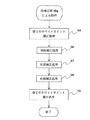
次に、図3を参照して、測色計によって測色されたカラーパッチのXYZデータに基づきLabデータを計算する方法を説明する。当該実施の形態では、外光を遮断した状態で既定の光源下で撮影を行い、光源としてはD50光源(色温度5000K)を使用する。
【0026】
図3のステップ50に示すように、基本的には、以下の3式
L = 116(Y/Yn)1/3−16 … (1)
a = 500((X/Xn)1/3−(Y/Yn)1/3) … (2)
b = 200((Y/Yn)1/3−(Z/Zn)1/3) … (3)
によって、XYZデータがLabデータに変換される。ここで、Xn、Yn、Znは、D50光源下におけるXYZ系の3刺激値である。
【0027】
但し、X/Xn≦0.008856(ステップ52、YES)の場合には、式(2)の(X/Xn)1/3が7.787(X/Xn)+16/116に置換され(ステップ54)、Y/Yn≦0.008856(ステップ56、YES)の場合には、式(1)〜(3)の(Y/Yn)1/3が7.787(Y/Yn)+16/116に置換され(ステップ58)、Z/Zn≦0.008856(ステップ60、YES)の場合には、式(3)の(Z/Zn)1/3が7.787(Z/Zn)+16/116に置換される(ステップ62)。
【0028】
このようにして、測色計によって測色されたカラーパッチのXYZデータに基づきLabデータが計算されて、基準画像データ計算・格納部30hに格納される。
【0029】
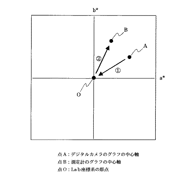
次に、色補正部30gによる色補正処理を説明する。図4に、色補正部30gによる色補正処理のフローチャートを示し、図5にグレー軸(ホワイトポイント)の移動を説明するための図を示す。
【0030】
当該色補正処理は、デジタルカメラの色画像データ値をグラフ化したもの(以下、「デジタルカメラのグラフ」と称する)と、測色計の色画像データ値をグラフ化したもの(以下、「測色計のグラフ」と称する)とを近づけるように行うが、デジタルカメラのグラフと測色計のグラフとの差は、ホワイトポイントの差、明度の差、各カラー毎の色相・彩度の差に分類することができ、これらは以下のように独立して補正される。
【0031】
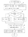
当該実施の形態によれば、色補正部30gは、デジタルカメラのグラフのグレー軸をLab空間のL軸に合わせるための第1のホワイトポイント補正処理(ステップ64)と;前記明度の差を補正するための明度補正処理(ステップ66)と;前記彩度の差を補正するための彩度補正処理(ステップ67)と;前記色相の差を補正するための色相補正処理(ステップ68)と;前記第1のホワイトポイント補正処理によってL軸に合わせられたデジタルカメラのグレー軸を測色計のグレー軸に合わせるための第2のホワイトポイント補正処理(ステップ70)と、からなる。
【0032】
第1のホワイトポイント補正処理(ステップ64)
まず、第1ホワイトポイント補正部30bによる処理を説明する。当該処理は、図5の点Aを点Oに移動させるための処理(処理▲1▼)に相当する。
【0033】
当該実施の形態においては、当該第1のホワイトポイントの補正を行った後に明度補正を行うように構成しているが、明度補正後に第1のホワイトポイントの補正を行なうようにすることもできる。
【0034】
色相補正の際の回転補正および彩度方向への伸縮補正を原点を中心にして行えるようにして、補正演算を簡易化するために、初めにデジタルカメラのグラフのグレー軸をLab空間のL軸に合わせ(図5の▲1▼の処理)、回転および彩度方向に関する補正を行う。
【0035】
Lab空間のL軸に対する、デジタルカメラのグラフのグレー軸の変位の方向および程度は、明度毎に異なるため、明度に応じた補正係数を決定する必要がある。補正係数は、補正の対象となる中心軸(グレー軸)のL*a*平面およびL*b*平面における近似曲線を導出して、明度Lの時の近似曲線の値がa*b*平面における移動距離になる。
【0036】
図6に、図4のステップ64における第1のホワイトポイント補正処理を説明するためのフローチャートを示す。
【0037】
L*a*平面における中心軸の近似3次曲線の式を
a*=a1×L3+b1×L2+c1×L+d1
(a1、b1、c1、d1は、それぞれ曲線の係数)とし、
L*b*平面における中心軸の近似3次曲線の式を
b*=a2×L3+b2×L2+c2×L+d2
(a2、b2、c2、d2は、それぞれ曲線の係数)とすると、明度Lにおける中心軸のa*方向への補正係数a* reviceと、b*方向への補正係数b* reviceは、
a* revice=a1×L3+b1×L2+c1×L+d1
b* revice=a2×L3+b2×L2+c2×L+d2
となる(ステップ72)。したがって、補正対象となるデジタルカメラのグラフの中心軸(グレー軸)のa*b*座標を(a* center,b* center)とした場合、補正後のa*b*座標(a* center’,b* center’)は、
a* center’=a* center+a* revice
b* center’=b* center+b* revice
となる(ステップ74)。
【0038】
明度補正処理(ステップ66)
次に、明度補正部30cによる明度補正処理を説明する。図7に、図4のステップ66における明度補正処理を説明するためのフローチャートを示す。
【0039】
明度の差は、明度が高い部分では大きく、明度の低い部分では小さい。このため、明度の高い部分での補正量を大きく、明度の低い部分での補正量を小さく設定する必要がある。まず、デジタルカメラの明度の最大値Lmax_DSC、および測色計の明度の最大値Lmax_STDを算出する(ステップ76)。そして、明度0の時の明度差がゼロであると仮定すると、補正対象となるデジタルカメラの明度がLmax_DSCの時の補正量は、Lmax_STD−Lmax_DSCであり、明度0の時の補正量は0になる。すなわち、明度が低くなるにしたがって、補正量がLmax_STD−Lmax_DSCから0になるような式を求める。なお、この時の補正量の変化は、明度が高いときは大きく、明度が低くなるにしたがって穏やかに変化するように設定することが好ましい。当該実施の形態では、明度Lにおける明度補正量L* reviceを
L* revice=(Lmax_STD−Lmax_DSC)×(L2/Lmax_DSC 2)
によって算出する(ステップ78)。
【0040】
色相・彩度の補正処理(ステップ67および68)
次に、色相・彩度補正部30dによる色相・彩度の補正処理を説明する。
【0041】
第1のホワイトポイント補正処理によって、デジタルカメラのグラフのグレー軸がLab空間のL軸と一致している。そこで、色相の補正は、Lab空間のL軸を中心として前記デジタルカメラのグラフを回転させることによって行い、彩度方向の補正は、デジタルカメラのグラフを伸縮させることによって行なう。この際、回転させる角度、および伸縮させる度合いが補正係数として必要になる。
【0042】
彩度方向への伸縮補正(ステップ67)
図8に、図4のステップ67における彩度補正処理を説明するためのフローチャートを示す。
【0043】
カラーチャートの所定のカラーパッチ点に対応するデジタルカメラのグラフ上の点Cおよび測色計のグラフ上の点Dに対して、a*b*平面上におけるそれぞれの中心から点Cおよび点Dまでの距離(半径rDSC、rSTD)を計算して、各カラー毎の演算処理を以下のように行い、彩度方向の伸縮係数を決定する。
【0044】
デジタルカメラのグラフの座標C(a* DSC,b* DSC)、デジタルカメラのグラフの中心軸(グレー軸)の座標 (a* DSC_center,b* DSC_center)、測色計のグラフの座標D(a* STD,b* STD)、および測色計のグラフの中心軸(グレー軸)の座標 (a* STD_center,b* STD_center)より、デジタルカメラのグラフの中心軸から点Cまでの距離rDSCおよび測色計のグラフの中心軸から点Dまでの距離rSTDは、
rDSC=((a* DSC−a* DSC_center)2+(b* DSC−b* DSC_center)2)1/2
rSTD=((a* STD−a* STD_center)2+(b* DSC−b* STD_center)2)1/2
により算出される(ステップ80)。さらに、彩度方向への伸縮補正係数をKとすると、彩度方向への伸縮補正を行なった後のrDSC'は、
rDSC'=(((a* DSC−a* DSC_center)×K)2+((b* DSC−b* DSC_center)×K)2)1/2
となり、各カラー毎の
Σ(rSTD−rDSC')2
が最小となるように、彩度方向への伸縮補正係数Kが算出される(ステップ82)。
【0045】
なお、彩度値に応じて、彩度の補正量を調整することもできる。
【0046】
色相方向への回転補正(ステップ68)
ステップ67において伸縮補正係数Kを求め、伸縮補正処理を行った後、a*b*平面上における、各中心軸(デジタルカメラのグラフのグレー軸および測色計のグラフの中心軸)を中心とした+a*軸からの角度を計算して各カラー毎の角度差の合計が最小になるように色相方向の回転補正係数を決定する。
【0047】
図9に、図4のステップ68における色相補正処理を説明するためのフローチャートを示す。
【0048】
色相(補正係数:α)、彩度(補正係数:K)による補正後のデジタルカメラの座標(a* DSC’,b* DSC’)は、
【0049】
【数1】
DDSC’=a×cos(a* DSC'/rDSC')
となる(ステップ88)。一方、a×sin(b* DSC'/rDSC')>0でない場合(ステップ86、No)、
DDSC’=360−a×cos(a* DSC'/rDSC')
となる(ステップ90)。そして、測色計のグラフのa*軸からの角度をDSTDとすると、色相方向への回転補正係数αは、各カラー毎の
Σ|DSTD −DDSC'|
を最小にする値として求まる(ステップ92)。
【0050】
補正の対象となるカラーのa*b*座標を(a*,b*)、色相方向への回転補正係数をα(単位:度)、彩度方向への伸縮補正係数をKとすると、補正後の座標(a*',b*')は、
【数2】
【0051】
中間色に対する補正処理
以上で求めた補正係数は、いずれも赤、緑、青、シアン、マゼンタ、イエローの純色付近の値であるため、そのまま中間色への補正に使用することはできない。そこで、中間色の場合には、以下のように補正係数の調整を行う。
【0052】
但し、補正係数の調整の際、ある境界線を境に急激な補正係数の変更を行えば当然カラーのジャンプが起こってしまう。したがって、補正係数の変化は色相の変化に伴って滑らかに行う必要がある。
【0053】
さらに、同一の補正係数を使用する場合であっても、グレー軸付近と外周付近とでは座標の移動距離が異なるため、グレー軸から遠ざかるに連れて補正を抑制しなければならない。
【0054】
中間色の補正係数を決定するためには、まず補正対象となる色がどのような色であるかを特定する必要がある。具体的には、測色計のグラフにおいて、グレー軸を中心としたときに赤、緑、青、シアン、マゼンタ、黄のグラフの近似直線と+a*軸とがなす角度を調べる。
【0055】
図10に、a*b*平面上において、グレー軸を中心としたときの各カラーの近似直線と+a*軸とがなす角度(以下、「色相角」と称する)を説明するための図を示す。図10に示すように、赤の近似直線と+a*軸とがなす角度は39°であり、黄の近似直線と+a*軸とがなす角度は84°であり、緑の近似直線と+a*軸とがなす角度は148°であり、シアンの近似直線と+a*軸とがなす角度は226°であり、青の近似直線と+a*軸とがなす角度は285°であり、マゼンタの近似直線と+a*軸とがなす角度は344°である。
【0056】
当該実施の形態では、補正対象となるカラーの色相角に基づき、上記6色のいずれの2色間に位置しているかを調べ、当該2色の近似曲線からの角度の比率に応じた重み付けを補正係数に対して行う。
【0057】
補正対象となるデジタルカメラのカラーの+a*軸からの色相角をθ、当該θを挟む2つのカラー(純色)の色相角、色相回転補正係数、彩度伸縮補正係数をそれぞれθ1、α1、k1、θ2、α2、k2とすると、補正対象となるカラーの補正係数α、kは、
【0058】
【数3】
【0059】
なお、本処理では、純色の範囲を[各純色の角度]±5°としており、当該範囲のカラーに対しては純色と同一の補正係数を使用する。
【0060】
第2のホワイトポイント補正処理(ステップ70)
さらに、第2ホワイトポイント補正部30eによる処理を説明する。当該処理は、図5の点Oを点Bに移動させるための処理(処理▲2▼)に相当する。
【0061】
Lab空間のL軸に対する、測色計のグラフのグレー軸の変位の方向および程度は、明度毎に異なるため、明度に応じた補正係数を決定する必要がある。補正係数は、補正の対象となる中心軸(グレー軸)のL*a*平面およびL*b*平面における近似曲線を導出して、明度Lの時の近似曲線の値がa*b*平面における移動距離になる。
【0062】
図11に、図4のステップ70における第2のホワイトポイント補正処理を説明するためのフローチャートを示す。
【0063】
L*a*平面における中心軸の近似3次曲線の式を
a*=a3×L3+b3×L2+c3×L+d3
(a3、b3、c3、d3は、それぞれ曲線の係数)とし、
L*b*平面における中心軸の近似3次曲線の式を
b*=a4×L3+b4×L2+c4×L+d4
(a4、b4、c4、d4は、それぞれ曲線の係数)とすると、明度Lにおける中心軸のa*方向への補正係数a* revice ’と、b*方向への補正係数b* revice ’は、
a* revice ’=a3×L3+b3×L2+c3×L+d3
b* revice ’=a4×L3+b4×L2+c4×L+d4
となる(ステップ96)。したがって、補正対象となるデジタルカメラのグラフの中心軸(グレー軸)のa*b*座標を(a* center ’,b* center ’)とした場合、補正後のa*b*座標(a* center",b* center"))は、
a* center"=a* center ’+a* revice ’
b* center"=b* center ’+b* revice ’
となる(ステップ98)。
【0064】
図12〜14に、色補正部30gによる色補正処理前(図12(a)、図13(a)および図14(a))および色補正処理後(図12(b)、図13(b)および図14(b))における測色計のグラフとデジタルカメラのグラフを示す。図12〜14において、R,Y,G,C,B,M(実線)は、測色計の赤、黄、緑、シアン、青、マゼンタの近似曲線を示し、R',Y',G',C',B',M'は、デジタルカメラの赤、黄、緑、シアン、青、マゼンタの近似曲線を示している。図12は測色計のグラフおよびデジタルカメラのグラフのa*b*平面上への投射を示し、図13は測色計のグラフおよびデジタルカメラのグラフのL*a*平面上への投射を示し、図14は測色計のグラフおよびデジタルカメラのグラフのL*b*平面上への投射を示している。図12〜14より、色補正処理により各純色の近似曲線が接近することが明らかになる。さらに、デジタルカメラのグラフと測色計のグラフとの対応する点間の距離の平均値ΔEが、色補正前で12.1であったのに対して、色補正により7.6に減少した。このことも、各純色の近似曲線が色補正処理により互いに接近することを示している。
【0065】
上記実施の形態においては、図6、図7、図8、図9および図11のフローチャートに示す数式によって色補正処理を行っているが、上記数式によって求められる色補正処理を色変換テーブルや簡易色変換テーブルによって行うこともできる。
【0066】
以上のように、色補正が施されたLab画像データは、第2画像データ変換部30fによってRGB画像データに変換されて色補正後の画像データとして出力される。そして、キャリブレーション(上記色補正)がなされた画像データがメモリカード16に記録され、LCD17に供給される。このようにして、忠実な色再現が可能なようにデジタルカメラをキャリブレーションすることができる。
【0067】
【発明の効果】
本発明による基準画像データに基づきデジタルカメラの画像データを色補正処理することによってデジタルカメラをキャリブレーションする方法、または記録媒体に記録されているプログラムの実行によれば、基準画像データの明度値、彩度値および色相角と、デジタルカメラの画像データの明度値、彩度値および色相角との差分が、前記複数の所定カラーに対してそれぞれ計算され、当該差分が所定の範囲内になるようにデジタルカメラの画像データを色補正処理しているので、所定のカラーに対するデジタルカメラの画像データの各色成分(明度値、彩度値および色相角)を基準画像データの各色成分に近づけることが可能となり、忠実な色再現が可能となる。
【図面の簡単な説明】
【図1】本発明の一実施の形態によるデジタルカメラを示すブロック図である。
【図2】本発明による画像処理制御部の機能ブロック図である。
【図3】測色計によって測色されたカラーパッチのXYZデータに基づきLabデータを計算する方法を説明するフローチャートである。
【図4】色補正部30gによる色補正処理を説明するフローチャートである。
【図5】グレー軸の移動を説明するための図である。
【図6】図4のステップ64における第1のホワイトポイント補正処理を説明するためのフローチャートである。
【図7】図4のステップ66における明度補正処理を説明するためのフローチャートである。
【図8】図4のステップ67における彩度補正処理を説明するためのフローチャートである。
【図9】図4のステップ68における色相補正処理を説明するためのフローチャートである。
【図10】グレー軸を中心としたときの各カラーの近似直線と+a*軸とがなす角度を説明するための図である。
【図11】図4のステップ70における第2のホワイトポイント補正処理を説明するためのフローチャートである。
【図12】測色計のグラフおよびデジタルカメラのグラフのa*b*平面上への投射を示し、(a)が色補正部30gによる色補正処理前の状態を示し、(b)が色補正処理後の状態を示している。
【図13】測色計のグラフおよびデジタルカメラのグラフのL*a*平面上への投射を示し、(a)が色補正部30gによる色補正処理前の状態を示し、(b)が色補正処理後の状態を示している。
【図14】測色計のグラフおよびデジタルカメラのグラフのL*b*平面上への投射を示し、(a)が色補正部30gによる色補正処理前の状態を示し、(b)が色補正処理後の状態を示している。
【符号の説明】
10 デジタルカメラ
11 制御部
12 集光レンズ
13 CCD
14 A/D変換器
15 RAM
16 フラッシュメモリ
17 LCD
18 VRAM
19 インターフェイス[0001]
BACKGROUND OF THE INVENTION
The present invention relates to a calibration method for adjusting a digital camera so that optimum color correction is performed on real image data captured by the digital camera, a digital camera subjected to color correction by the calibration method, and a recording It relates to the medium.
[0002]
[Prior art]
As an image processing apparatus that handles high-quality image data using a computer or the like, light is converted into an electrical signal by an imaging means such as a CCD, and the electrical signal is converted into digital data and recorded on a recording medium such as a flash memory. Digital cameras are known. Using a digital camera, you can easily save image data and perform various processing by using a personal computer, and print images without developing the film by outputting the image data to a printer. it can.
[0003]
[Problems to be solved by the invention]
However, in the conventional digital camera, appropriate color correction is not made, and when an image captured by the conventional digital camera is output to the output device, it differs from the actual image in terms of brightness, saturation, and hue. And faithful color reproduction was not made.
[0004]
The present invention has been made to solve the above-described problems. A method for calibrating a digital camera so that faithful color reproduction is possible, and a digital camera and a recording medium that have been color-corrected by the calibration method are provided. The issue is to provide.
[0005]
[Means for Solving the Problems]
In view of the above problems, the invention according to claim 1 is based on the reference image data.Imaging deviceBy color-correcting the image dataImaging deviceA first calculation step of calculating brightness values, saturation values and hue angles of the reference image data for a plurality of predetermined colors in a predetermined color system; and the predetermined color system InImaging deviceThe plurality of predetermined colors imaged byImaging deviceA second calculation step of calculating the lightness value, saturation value and hue angle of the image data, and the lightness value, saturation value and hue angle of the reference image data calculated by the first calculation step, and the second calculation step calculatedImaging deviceA difference calculation step of calculating the difference between the brightness value, the saturation value, and the hue angle of the image data for each of the plurality of predetermined colors, and the brightness value and the saturation calculated by the difference calculation step The difference between the value and the hue angle is within the predetermined range.Imaging deviceThe image data is subjected to color correction processing.
[0006]
Based on the reference image data configured as described above,Imaging deviceBy color-correcting the image dataImaging deviceAccording to the method for calibrating the image, the lightness value, the saturation value, and the hue angle of the reference image data for a plurality of predetermined colors are calculated in a predetermined color system by the first calculation step, and the second calculation step In the predetermined color system,Imaging deviceThe plurality of predetermined colors imaged byImaging deviceThe brightness value, saturation value, and hue angle of the image data are calculated. Then, by the difference calculation step, the lightness value, the saturation value and the hue angle of the reference image data calculated by the first calculation step and the second calculation step are calculated.Imaging deviceDifferences between the brightness value, the saturation value, and the hue angle of the image data are calculated for each of the plurality of predetermined colors. The difference between the brightness value, saturation value, and hue angle calculated in this way is within a predetermined range.Imaging deviceThe image data is subjected to color correction processing.
[0007]
The invention according to
[0008]
Furthermore, the invention according to claim 3 is the calibration method according to
[0009]
The invention according to
[0010]
Furthermore, the invention according to claim 5 is the calibration method according to any one of claims 1 to 4, wherein the correction is performed at a predetermined hue angle based on a correction amount of the hue angle with respect to the reference color.Imaging deviceAnd a hue correction step for determining the correction amount of the image data.
[0011]
In view of the above problems, the invention according to
[0012]
In view of the above problems, the invention according to claim 7 is based on the reference image data,Imaging deviceBy color-correcting the image dataImaging deviceA computer-readable recording medium storing a program for causing a computer to execute a calibration process, wherein the brightness value and the saturation value of the reference image data for a plurality of predetermined colors in a predetermined color system And a first calculation process for calculating a hue angle and the predetermined color system,Imaging deviceThe plurality of predetermined colors imaged byImaging deviceA second calculation process for calculating the lightness value, the saturation value, and the hue angle of the image data; the lightness value, the saturation value, and the hue angle of the reference image data calculated by the first calculation process; and the second calculation process. calculatedImaging deviceDifference calculation processing for calculating the difference between the brightness value, the saturation value, and the hue angle of the image data for each of the plurality of predetermined colors, and the brightness value and saturation calculated by the difference calculation processing The difference between the value and the hue angle is within the predetermined range.Imaging deviceColor correction of image dataImaging deviceA program for causing the computer to execute the calibration process is recorded and can be read by the computer.
[0013]
According to the computer-readable recording medium configured as described above, based on the reference image data,Imaging deviceBy color-correcting the image dataImaging deviceA program for causing a computer to execute a process for calibrating the computer is recorded. By executing the program, the lightness value, the saturation value, and the hue angle of the reference image data for a plurality of predetermined colors in the predetermined color system are calculated by the first calculation process, and the predetermined calculation is performed by the second calculation process. In the color system ofImaging deviceThe plurality of predetermined colors imaged byImaging deviceThe brightness value, saturation value, and hue angle of the image data are calculated. Then, by the difference calculation process, the brightness value, the saturation value, and the hue angle of the reference image data calculated by the first calculation process, and the second calculation processImaging deviceThe difference between the brightness value, the saturation value, and the hue angle of the image data is calculated for each of the plurality of predetermined colors, and the difference between the brightness value, the saturation value, and the hue angle calculated by the difference calculation processing is calculated. To be within the prescribed rangeImaging deviceThe image data is color corrected.
[0014]
DETAILED DESCRIPTION OF THE INVENTION
Preferred embodiments of the present invention will be described below with reference to the drawings.
[0015]
FIG. 1 is a block diagram for explaining the structure of a
[0016]
The
[0017]
As the
[0018]
A program for executing a calibration process for a digital camera according to the present invention is normally recorded and distributed on a recording medium such as a floppy disk or a CD-ROM in a computer-readable form. The program is read by the media reader and written in the ROM. The CPU is configured to read a desired program from the ROM as appropriate and execute a desired process.
[0019]
FIG. 2 is a functional block diagram of the image processing control unit 30 according to an embodiment of the present invention. An image processing control unit 30 that performs calibration of a digital camera according to an embodiment of the present invention is configured by the
[0020]
As shown in FIG. 2, the image processing control unit 30 configured by the
[0021]
The color correction unit 30g includes a first white
[0022]
Next, the operation of the image processing control unit 30 will be described with reference to FIG.
[0023]
While the image taken by the
[0024]
As shown in FIG. 2, RGB image data generated based on each color patch imaged by the digital camera is first converted into Lab image data by the first
[0025]
Next, a method of calculating Lab data based on XYZ data of color patches measured by a colorimeter will be described with reference to FIG. In this embodiment, photographing is performed under a predetermined light source in a state where external light is blocked, and a D50 light source (color temperature 5000K) is used as the light source.
[0026]
Basically, as shown in
L = 116 (Y / Yn)1/3-16 (1)
a = 500 ((X / Xn)1/3-(Y / Yn)1/3(2)
b = 200 ((Y / Yn)1/3-(Z / Zn)1/3(3)
Thus, the XYZ data is converted into Lab data. Here, Xn, Yn, and Zn are XYZ tristimulus values under a D50 light source.
[0027]
However, in the case of X / Xn ≦ 0.008856 (
[0028]
In this way, Lab data is calculated based on the XYZ data of the color patch measured by the colorimeter, and stored in the reference image data calculation /
[0029]
Next, color correction processing by the color correction unit 30g will be described. FIG. 4 shows a flowchart of color correction processing by the color correction unit 30g, and FIG. 5 shows a diagram for explaining the movement of the gray axis (white point).
[0030]
The color correction processing includes a graph of color image data values of a digital camera (hereinafter referred to as “digital camera graph”) and a graph of color image data values of a colorimeter (hereinafter referred to as “measurement”). The difference between the digital camera graph and the colorimeter graph is the difference in white point, brightness, and hue / saturation for each color. These are independently corrected as follows:
[0031]
According to the embodiment, the color correction unit 30g performs the first white point correction process (step 64) for adjusting the gray axis of the graph of the digital camera to the L axis of the Lab space; and corrects the difference in brightness. Brightness correction processing (step 66); and saturation correction processing (step 67) for correcting the saturation difference; hue correction processing (step 68) for correcting the hue difference; And a second white point correction process (step 70) for adjusting the gray axis of the digital camera adjusted to the L axis by the first white point correction process to the gray axis of the colorimeter.
[0032]
First white point correction process (step 64)
First, the processing by the first white
[0033]
In the embodiment, the lightness correction is performed after the first white point is corrected. However, the first white point may be corrected after the lightness correction.
[0034]
In order to simplify the correction calculation so that the rotation correction in the hue correction and the expansion / contraction correction in the saturation direction can be performed around the origin, the gray axis of the digital camera graph is first set to the L axis of the Lab space. (Step (1) in FIG. 5) and correction related to rotation and saturation direction.
[0035]
Since the direction and degree of displacement of the gray axis of the digital camera graph with respect to the L axis in the Lab space differ for each brightness, it is necessary to determine a correction coefficient corresponding to the brightness. The correction coefficient is L of the central axis (gray axis) to be corrected.*a*Plane and L*b*Deriving an approximate curve in the plane, the value of the approximate curve at lightness L is a*b*It becomes the movement distance in the plane.
[0036]
FIG. 6 shows a flowchart for explaining the first white point correction processing in
[0037]
L*a*The equation of the approximate cubic curve of the central axis in the plane
a*= A1 x LThree+ B1 × L2+ C1 × L + d1
(A1, b1, c1, and d1 are coefficients of a curve, respectively)
L*b*The equation of the approximate cubic curve of the central axis in the plane
b*= A2 × LThree+ B2 × L2+ C2 × L + d2
Assuming that (a2, b2, c2, and d2 are coefficients of a curve, respectively), the central axis a at lightness L*Correction factor a* reviceAnd b*Correction factor b in the direction* reviceIs
a* revice= A1 x LThree+ B1 × L2+ C1 × L + d1
b* revice= A2 × LThree+ B2 × L2+ C2 × L + d2
(Step 72). Therefore, a of the central axis (gray axis) of the graph of the digital camera to be corrected*b*Coordinates (a* center, B* centerA) after correction*b*Coordinates (a* center', B* center’)
a* center‘= A* center+ A* revice
b* center'= B* center+ B* revice
(Step 74).
[0038]
Lightness correction processing (step 66)
Next, lightness correction processing by the
[0039]
The difference in lightness is large in a portion with high lightness and small in a portion with low lightness. For this reason, it is necessary to set a large correction amount in a portion with high lightness and a small correction amount in a portion with low lightness. First, the maximum brightness L of the digital cameramax_DSC, And the maximum lightness L of the colorimetermax_STDIs calculated (step 76). Assuming that the brightness difference when the brightness is 0 is zero, the brightness of the digital camera to be corrected is Lmax_DSCThe correction amount at the time is Lmax_STD-Lmax_DSCThe correction amount when the brightness is 0 is 0. That is, as the brightness decreases, the correction amount becomes Lmax_STD-Lmax_DSCFind an expression that becomes 0 from. The change in the correction amount at this time is preferably set so that it is large when the lightness is high and changes gently as the lightness becomes low. In this embodiment, the lightness correction amount L at lightness L* reviceThe
L* revice= (Lmax_STD-Lmax_DSC) X (L2/ Lmax_DSC 2)
(Step 78).
[0040]
Hue / saturation correction processing (
Next, hue / saturation correction processing by the hue /
[0041]
By the first white point correction process, the gray axis of the graph of the digital camera coincides with the L axis of the Lab space. Therefore, the hue correction is performed by rotating the digital camera graph around the L axis of the Lab space, and the saturation direction correction is performed by expanding and contracting the digital camera graph. At this time, the rotation angle and the degree of expansion / contraction are required as correction coefficients.
[0042]
Stretching correction in the saturation direction (step 67)
FIG. 8 is a flowchart for explaining the saturation correction processing in
[0043]
For point C on the digital camera graph and point D on the colorimeter graph corresponding to a predetermined color patch point on the color chart, a*b*Distance from each center on the plane to points C and D (radius rDSC, RSTD) And the calculation process for each color is performed as follows to determine the expansion / contraction coefficient in the saturation direction.
[0044]
Digital camera graph coordinates C (a* DSC, B* DSC), Coordinates of the central axis (gray axis) of the digital camera graph (a* DSC_center, B* DSC_center), Coordinate D (a* STD, B* STD), And coordinates of the central axis (gray axis) of the colorimeter graph (a* STD_center, B* STD_center), The distance r from the central axis of the digital camera graph to point CDSCAnd the distance r from the central axis of the colorimeter graph to point DSTDIs
rDSC= ((A* DSC-A* DSC_center)2+ (B* DSC-B* DSC_center)2)1/2
rSTD= ((A* STD-A* STD_center)2+ (B* DSC-B* STD_center)2)1/2
(Step 80). Further, if the expansion / contraction correction coefficient in the saturation direction is K, r after the expansion / contraction correction in the saturation direction is performed.DSC'
rDSC'= (((A* DSC-A* DSC_center) × K)2+ ((B* DSC-B* DSC_center) × K)2)1/2
And for each color
Σ (rSTD-RDSC')2
The expansion / contraction correction coefficient K in the saturation direction is calculated so that is minimized (step 82).
[0045]
Note that the saturation correction amount can be adjusted according to the saturation value.
[0046]
Rotation correction in the hue direction (step 68)
After obtaining the expansion / contraction correction coefficient K in
[0047]
FIG. 9 is a flowchart for explaining the hue correction processing in
[0048]
Digital camera coordinates after correction by hue (correction coefficient: α) and saturation (correction coefficient: K) (a* DSC', B* DSC’)
[0049]
[Expression 1]
DDSC‘= A × cos (a* DSC'/ RDSC')
(Step 88). On the other hand, a × sin (b* DSC'/ RDSC') If not> 0 (
DDSC′ = 360−a × cos (a* DSC'/ RDSC')
(Step 90). And a of the graph of the colorimeter*The angle from the axis is DSTDThen, the rotation correction coefficient α in the hue direction is
Σ | DSTD -DDSC'|
Is obtained as a value that minimizes (step 92).
[0050]
A for the color to be corrected*b*Coordinates (a*, B*), When the rotation correction coefficient in the hue direction is α (unit: degree) and the expansion / contraction correction coefficient in the saturation direction is K, the corrected coordinates (a*', B*')
[Expression 2]
[0051]
Correction processing for intermediate colors
The correction coefficients obtained above are values in the vicinity of pure colors of red, green, blue, cyan, magenta, and yellow, and cannot be used for correction to intermediate colors as they are. Therefore, in the case of an intermediate color, the correction coefficient is adjusted as follows.
[0052]
However, when the correction coefficient is adjusted, if the correction coefficient is suddenly changed with a certain boundary line as a boundary, a color jump naturally occurs. Therefore, it is necessary to smoothly change the correction coefficient as the hue changes.
[0053]
Further, even when the same correction coefficient is used, since the coordinate movement distance is different between the vicinity of the gray axis and the vicinity of the outer periphery, the correction must be suppressed as the distance from the gray axis is increased.
[0054]
In order to determine the correction coefficient for the intermediate color, it is first necessary to specify what color the correction target color is. Specifically, in the colorimeter graph, the approximate straight line of the graph of red, green, blue, cyan, magenta, and yellow and + a when the gray axis is the center.*Check the angle between the axis.
[0055]
In FIG.*b*On the plane, the approximate straight line of each color with the gray axis as the center and + a*The figure for demonstrating the angle (henceforth "hue angle") which an axis | shaft makes is shown. As shown in FIG. 10, the approximate red line and + a*The angle formed by the axis is 39 °, and the yellow approximate line and + a*The angle formed by the axis is 84 °, and the green approximate straight line and + a*The angle formed by the axis is 148 °, and the approximate straight line of cyan and + a*The angle formed by the axis is 226 °, and the blue approximate straight line and + a*The angle formed by the axis is 285 °, and the approximate straight line of magenta and + a*The angle formed by the axis is 344 °.
[0056]
In this embodiment, based on the hue angle of the color to be corrected, it is checked which of the six colors is located between the two colors, and weighting is performed according to the angle ratio from the approximate curve of the two colors. Do this for the correction factor.
[0057]
+ A of the color of the digital camera to be corrected*The hue angle from the axis is θ, and the hue angle, hue rotation correction coefficient, and saturation expansion / contraction correction coefficient of two colors (pure colors) sandwiching the θ are θ, respectively.1, Α1, K1, Θ2, Α2, K2Then, the correction coefficients α and k of the color to be corrected are
[0058]
[Equation 3]
[0059]
In this process, the pure color range is set to [angle of each pure color] ± 5 °, and the same correction coefficient as that of the pure color is used for the color in the range.
[0060]
Second white point correction process (step 70)
Further, processing by the second white
[0061]
Since the direction and degree of displacement of the gray axis of the colorimeter graph with respect to the L axis of the Lab space differ for each lightness, it is necessary to determine a correction coefficient corresponding to the lightness. The correction coefficient is L of the central axis (gray axis) to be corrected.*a*Plane and L*b*Deriving an approximate curve in the plane, the value of the approximate curve at lightness L is a*b*It becomes the movement distance in the plane.
[0062]
FIG. 11 is a flowchart for explaining the second white point correction process in
[0063]
L*a*The equation of the approximate cubic curve of the central axis in the plane
a*= A3 × LThree+ B3 × L2+ C3 × L + d3
(A3, b3, c3, d3 are the coefficients of the curve, respectively)
L*b*The equation of the approximate cubic curve of the central axis in the plane
b*= A4 × LThree+ B4 × L2+ C4 × L + d4
(Where a4, b4, c4, and d4 are coefficients of a curve, respectively)*Correction factor a* revice 'And b*Correction factor b in the direction* revice 'Is
a* revice '= A3 × LThree+ B3 × L2+ C3 × L + d3
b* revice '= A4 × LThree+ B4 × L2+ C4 × L + d4
(Step 96). Therefore, a of the central axis (gray axis) of the graph of the digital camera to be corrected*b*Coordinates (a* center ', B* center 'A) after correction*b*Coordinates (a* center", B* center"))
a* center"= A* center '+ A* revice '
b* center"= B* center '+ B* revice '
(Step 98).
[0064]
FIGS. 12 to 14 show the color correction unit 30g before color correction processing (FIG. 12A, FIG. 13A and FIG. 14A) and after color correction processing (FIGS. 12B and 13B). ) And the graph of the colorimeter and the digital camera in FIG. 12 to 14, R, Y, G, C, B, and M (solid lines) indicate approximate curves of red, yellow, green, cyan, blue, and magenta of the colorimeter, and R ′, Y ′, G ', C', B ', M' indicate approximate curves of red, yellow, green, cyan, blue and magenta of the digital camera. FIG. 12 shows a graph of a colorimeter graph and a digital camera graph.*b*FIG. 13 shows the projection onto the plane, and FIG. 13 shows the L of the colorimeter graph and the digital camera graph.*a*FIG. 14 shows the projection onto the plane, and FIG. 14 shows the L of the colorimeter graph and the digital camera graph.*b*A projection onto a plane is shown. 12-14, it becomes clear that the approximate curve of each pure color approaches by color correction processing. Further, the average value ΔE of the distance between corresponding points on the digital camera graph and the colorimeter graph was 12.1 before color correction, but decreased to 7.6 by color correction. . This also indicates that the approximate curves of the pure colors approach each other by the color correction process.
[0065]
In the above embodiment, the color correction processing is performed by the mathematical formulas shown in the flowcharts of FIGS. 6, 7, 8, 9, and 11. However, the color correction processing obtained by the mathematical formula is performed using a color conversion table or a simple method. It can also be performed by a color conversion table.
[0066]
As described above, the Lab image data subjected to color correction is converted into RGB image data by the second image
[0067]
【The invention's effect】
According to the method of calibrating a digital camera by performing color correction processing on the image data of the digital camera based on the reference image data according to the present invention, or according to the execution of a program recorded on a recording medium, the brightness value of the reference image data, Differences between the saturation value and hue angle and the lightness value, saturation value and hue angle of the image data of the digital camera are calculated for each of the plurality of predetermined colors so that the difference falls within a predetermined range. Since digital camera image data is color corrected, each color component (brightness value, saturation value, and hue angle) of the digital camera image data for a given color can be brought close to each color component of the reference image data. Thus, faithful color reproduction is possible.
[Brief description of the drawings]
FIG. 1 is a block diagram showing a digital camera according to an embodiment of the present invention.
FIG. 2 is a functional block diagram of an image processing control unit according to the present invention.
FIG. 3 is a flowchart illustrating a method for calculating Lab data based on XYZ data of color patches measured by a colorimeter.
FIG. 4 is a flowchart illustrating color correction processing by a color correction unit 30g.
FIG. 5 is a diagram for explaining a movement of a gray axis.
FIG. 6 is a flowchart for explaining first white point correction processing in
7 is a flowchart for explaining brightness correction processing in step 66 of FIG. 4; FIG.
FIG. 8 is a flowchart for explaining a saturation correction process in
FIG. 9 is a flowchart for explaining hue correction processing in
FIG. 10 shows an approximate straight line of each color when the gray axis is the center and + a*It is a figure for demonstrating the angle which an axis | shaft makes.
FIG. 11 is a flowchart for explaining a second white point correction process in
12 is a graph of a colorimeter graph and a digital camera graph. FIG.*b*The projection onto the plane is shown, (a) shows the state before the color correction processing by the color correction unit 30g, and (b) shows the state after the color correction processing.
FIG. 13 is a graph of a colorimeter graph and a digital camera graph L*a*The projection onto the plane is shown, (a) shows the state before the color correction processing by the color correction unit 30g, and (b) shows the state after the color correction processing.
FIG. 14 is a graph of a colorimeter graph and a digital camera graph L*b*The projection onto the plane is shown, (a) shows the state before the color correction processing by the color correction unit 30g, and (b) shows the state after the color correction processing.
[Explanation of symbols]
10 Digital camera
11 Control unit
12 Condensing lens
13 CCD
14 A / D converter
15 RAM
16 Flash memory
17 LCD
18 VRAM
19 Interface
Claims (6)
所定の表色系において、複数の所定カラーに対する前記基準画像データの明度値、彩度値および色相角を計算する第1計算工程と、
前記所定の表色系において、画像撮像装置によって撮像された前記複数の所定カラーに対する前記画像撮像装置の画像データの明度値、彩度値および色相角を計算する第2計算工程と、
第1計算工程によって計算された基準画像データの明度値、彩度値および色相角と、第2計算工程によって計算された画像撮像装置の画像データの明度値、彩度値および色相角との差分を、前記複数の所定カラーに対してそれぞれ計算する差分計算工程と、
を備え、前記差分計算工程によって計算された明度値、彩度値および色相角の差分が所定の範囲内になるように画像撮像装置の画像データを色補正処理し、
前記画像撮像装置の彩度値および色相角に関する画像データ処理前に、画像撮像装置の画像データのグレー軸を前記所定の表色系のグレー軸に一致させ、前記画像撮像装置の彩度値および色相角に関する画像データ処理後に、前記所定の表色系のグレー軸に一致している画像撮像装置の画像データのグレー軸を基準画像データのグレー軸に一致させるグレー軸移動工程をさらに備えている、
画像撮像装置のキャリブレーション方法。A method for calibrating an image pickup device by performing color correction processing on image data of the image pickup device based on reference image data,
A first calculation step of calculating a brightness value, a saturation value, and a hue angle of the reference image data for a plurality of predetermined colors in a predetermined color system;
A second calculation step of calculating a brightness value, a saturation value, and a hue angle of image data of the image pickup device for the plurality of predetermined colors picked up by the image pickup device in the predetermined color system;
Differences between the lightness value, saturation value, and hue angle of the reference image data calculated in the first calculation step, and the lightness value, saturation value, and hue angle of the image data of the image pickup device calculated in the second calculation step Difference calculating step for calculating each of the plurality of predetermined colors,
The image data of the image pickup device is subjected to color correction processing so that the difference between the brightness value, the saturation value, and the hue angle calculated by the difference calculation step is within a predetermined range,
Before the image data processing related to the saturation value and hue angle of the image pickup device, the gray axis of the image data of the image pickup device is matched with the gray axis of the predetermined color system, and the saturation value of the image pickup device and After the image data processing relating to the hue angle, the image processing apparatus further includes a gray axis moving step of matching the gray axis of the image data of the image pickup device that matches the gray axis of the predetermined color system with the gray axis of the reference image data. ,
A calibration method for an image pickup apparatus.
所定の表色系において、複数の所定カラーに対する前記基準画像データの明度値、彩度値および色相角を計算する第1計算処理と、
前記所定の表色系において、画像撮像装置によって撮像された前記複数の所定カラーに対する前記画像撮像装置の画像データの明度値、彩度値および色相角を計算する第2計算処理と、
第1計算処理によって計算された基準画像データの明度値、彩度値および色相角と、第2計算処理によって計算された画像撮像装置の画像データの明度値、彩度値および色相角との差分を、前記複数の所定カラーに対してそれぞれ計算する差分計算処理と、
を備え、前記差分計算処理によって計算された明度値、彩度値および色相角の差分が所定の範囲内になるように画像撮像装置の画像データを色補正し、
前記画像撮像装置の彩度値および色相角に関する画像データ処理前に、画像撮像装置の画像データのグレー軸を前記所定の表色系のグレー軸に一致させ、前記画像撮像装置の彩度値および色相角に関する画像データ処理後に、前記所定の表色系のグレー軸に一致している画像撮像装置の画像データのグレー軸を基準画像データのグレー軸に一致させるグレー軸移動処理をさらに備えている画像撮像装置のキャリブレーション処理をコンピュータに実行させるためのプログラムを記録したコンピュータによって読取可能な記録媒体。A computer-readable recording medium recording a program for causing a computer to execute a process of calibrating the image pickup device by performing color correction processing on the image data of the image pickup device based on reference image data,
A first calculation process for calculating a brightness value, a saturation value, and a hue angle of the reference image data for a plurality of predetermined colors in a predetermined color system;
A second calculation process for calculating a lightness value, a saturation value, and a hue angle of image data of the image pickup device for the plurality of predetermined colors imaged by the image pickup device in the predetermined color system;
Difference between brightness value, saturation value and hue angle of reference image data calculated by first calculation process and brightness value, saturation value and hue angle of image data of image pickup apparatus calculated by second calculation process A difference calculation process for calculating each of the plurality of predetermined colors,
And color-correcting the image data of the image pickup device so that the difference between the brightness value, the saturation value, and the hue angle calculated by the difference calculation process is within a predetermined range,
Before the image data processing related to the saturation value and hue angle of the image pickup device, the gray axis of the image data of the image pickup device is matched with the gray axis of the predetermined color system, and the saturation value of the image pickup device and After the image data processing relating to the hue angle, the image processing apparatus further includes a gray axis movement process for matching the gray axis of the image data of the image pickup apparatus that matches the gray axis of the predetermined color system with the gray axis of the reference image data. A computer-readable recording medium storing a program for causing a computer to execute calibration processing of an image pickup apparatus.
Priority Applications (1)
| Application Number | Priority Date | Filing Date | Title |
|---|---|---|---|
| JP2000012299A JP3855574B2 (en) | 2000-01-20 | 2000-01-20 | Calibration method for image pickup apparatus, image pickup apparatus subjected to color correction by the calibration method, and recording medium |
Applications Claiming Priority (1)
| Application Number | Priority Date | Filing Date | Title |
|---|---|---|---|
| JP2000012299A JP3855574B2 (en) | 2000-01-20 | 2000-01-20 | Calibration method for image pickup apparatus, image pickup apparatus subjected to color correction by the calibration method, and recording medium |
Publications (3)
| Publication Number | Publication Date |
|---|---|
| JP2001204041A JP2001204041A (en) | 2001-07-27 |
| JP2001204041A5 JP2001204041A5 (en) | 2005-02-24 |
| JP3855574B2 true JP3855574B2 (en) | 2006-12-13 |
Family
ID=18540036
Family Applications (1)
| Application Number | Title | Priority Date | Filing Date |
|---|---|---|---|
| JP2000012299A Expired - Fee Related JP3855574B2 (en) | 2000-01-20 | 2000-01-20 | Calibration method for image pickup apparatus, image pickup apparatus subjected to color correction by the calibration method, and recording medium |
Country Status (1)
| Country | Link |
|---|---|
| JP (1) | JP3855574B2 (en) |
Families Citing this family (9)
| Publication number | Priority date | Publication date | Assignee | Title |
|---|---|---|---|---|
| US7570282B1 (en) * | 1998-12-09 | 2009-08-04 | Aptina Imaging Corporation | Color correction of multiple colors using a calibrated technique |
| KR20040009966A (en) * | 2002-07-26 | 2004-01-31 | 삼성전자주식회사 | Apparatus and method for correcting color |
| WO2004098175A1 (en) * | 2003-04-30 | 2004-11-11 | Toshiba Matsushita Display Technology Co. Ltd. | Image magnification device |
| KR100731812B1 (en) * | 2006-08-11 | 2007-06-22 | 엠텍비젼 주식회사 | Color deviation compensating apparatus and method, image processor using it, recorded medium |
| FR2905007B1 (en) * | 2006-08-16 | 2008-10-31 | Essilor Int | QUANTITAVE EVALUATION OF A COLOR FILTER |
| JP4958672B2 (en) * | 2007-07-25 | 2012-06-20 | キヤノン株式会社 | Imaging apparatus and control method thereof |
| US8130236B2 (en) | 2008-02-05 | 2012-03-06 | Aptina Imaging Corporation | Systems and methods to achieve preferred imager color reproduction |
| JP5367455B2 (en) * | 2008-06-04 | 2013-12-11 | Toa株式会社 | Apparatus and method for color adjustment between a plurality of color cameras |
| CN117249904B (en) * | 2023-11-15 | 2024-02-13 | 深圳市宗匠科技有限公司 | Calibration method and device of color sensor, cosmetic mask and storage medium |
-
2000
- 2000-01-20 JP JP2000012299A patent/JP3855574B2/en not_active Expired - Fee Related
Also Published As
| Publication number | Publication date |
|---|---|
| JP2001204041A (en) | 2001-07-27 |
Similar Documents
| Publication | Publication Date | Title |
|---|---|---|
| EP1592227B1 (en) | Apparatus and method for determining an image processing parameter from image data at a user-selected image position | |
| EP1977615B1 (en) | Automatic color calibration of an image sensor | |
| JP6455764B2 (en) | Color correction parameter calculation method, color correction parameter calculation device, and image output system | |
| US20060290957A1 (en) | Apparatus, medium, and method with automatic white balance control | |
| JP3903083B2 (en) | Image processing apparatus, method, and recording medium | |
| US20050207629A1 (en) | Imaging apparatus, image processing apparatus, image processing system and image processing method | |
| JP2000311243A (en) | Image color correction method and device | |
| JP2005117612A (en) | Image processing method and apparatus | |
| KR20140035349A (en) | Colour calibration method for an image capture device | |
| JP2005210370A (en) | Image processor, photographic device, image processing method, image processing program | |
| JP2005210526A (en) | Image processing apparatus, method, and program, image pickup device, and image data outputting method and program | |
| JP2006211369A (en) | Color conversion matrix calculation method and picture signal processor | |
| US8502881B2 (en) | Image processing apparatus, image processing method, and electronic camera | |
| JP5757932B2 (en) | Image correction data generation apparatus and image correction data generation program | |
| JP2007036462A (en) | Image processing apparatus | |
| JP3907810B2 (en) | Three-dimensional lookup table correction method, image processing apparatus for performing the same, and digital color printer having the same | |
| JP3855574B2 (en) | Calibration method for image pickup apparatus, image pickup apparatus subjected to color correction by the calibration method, and recording medium | |
| US20100046834A1 (en) | Color processing apparatus and method thereof | |
| JP2005210495A (en) | Image processing apparatus, method, and program | |
| JP4031299B2 (en) | Color image signal processing method, color image output apparatus, and photographing apparatus | |
| JP2004088345A (en) | Image forming method, image processor, print preparation device, and storage medium | |
| JP2005045446A (en) | Color conversion matrix calculation method and color correction method | |
| JP5121206B2 (en) | Image processing apparatus, image processing program, and image processing method | |
| JP2005117524A (en) | Image processing system | |
| JP2006222783A (en) | Preparation of color conversion table |
Legal Events
| Date | Code | Title | Description |
|---|---|---|---|
| A521 | Request for written amendment filed |
Free format text: JAPANESE INTERMEDIATE CODE: A523 Effective date: 20040325 |
|
| A621 | Written request for application examination |
Free format text: JAPANESE INTERMEDIATE CODE: A621 Effective date: 20040325 |
|
| RD02 | Notification of acceptance of power of attorney |
Free format text: JAPANESE INTERMEDIATE CODE: A7422 Effective date: 20040325 |
|
| A977 | Report on retrieval |
Free format text: JAPANESE INTERMEDIATE CODE: A971007 Effective date: 20060623 |
|
| A131 | Notification of reasons for refusal |
Free format text: JAPANESE INTERMEDIATE CODE: A131 Effective date: 20060628 |
|
| A521 | Request for written amendment filed |
Free format text: JAPANESE INTERMEDIATE CODE: A523 Effective date: 20060731 |
|
| TRDD | Decision of grant or rejection written | ||
| A01 | Written decision to grant a patent or to grant a registration (utility model) |
Free format text: JAPANESE INTERMEDIATE CODE: A01 Effective date: 20060822 |
|
| A61 | First payment of annual fees (during grant procedure) |
Free format text: JAPANESE INTERMEDIATE CODE: A61 Effective date: 20060904 |
|
| R150 | Certificate of patent or registration of utility model |
Free format text: JAPANESE INTERMEDIATE CODE: R150 |
|
| FPAY | Renewal fee payment (event date is renewal date of database) |
Free format text: PAYMENT UNTIL: 20090922 Year of fee payment: 3 |
|
| FPAY | Renewal fee payment (event date is renewal date of database) |
Free format text: PAYMENT UNTIL: 20100922 Year of fee payment: 4 |
|
| FPAY | Renewal fee payment (event date is renewal date of database) |
Free format text: PAYMENT UNTIL: 20100922 Year of fee payment: 4 |
|
| FPAY | Renewal fee payment (event date is renewal date of database) |
Free format text: PAYMENT UNTIL: 20110922 Year of fee payment: 5 |
|
| FPAY | Renewal fee payment (event date is renewal date of database) |
Free format text: PAYMENT UNTIL: 20120922 Year of fee payment: 6 |
|
| FPAY | Renewal fee payment (event date is renewal date of database) |
Free format text: PAYMENT UNTIL: 20130922 Year of fee payment: 7 |
|
| LAPS | Cancellation because of no payment of annual fees |