JP3855352B2 - Electrophotographic copying machine - Google Patents
Electrophotographic copying machine Download PDFInfo
- Publication number
- JP3855352B2 JP3855352B2 JP09547797A JP9547797A JP3855352B2 JP 3855352 B2 JP3855352 B2 JP 3855352B2 JP 09547797 A JP09547797 A JP 09547797A JP 9547797 A JP9547797 A JP 9547797A JP 3855352 B2 JP3855352 B2 JP 3855352B2
- Authority
- JP
- Japan
- Prior art keywords
- roller
- paper
- transfer
- sheet
- pair
- Prior art date
- Legal status (The legal status is an assumption and is not a legal conclusion. Google has not performed a legal analysis and makes no representation as to the accuracy of the status listed.)
- Expired - Lifetime
Links
Images

Description
【0001】
【発明の属する技術分野】
本発明は電子写真複写装置の紙搬送における紙粉除去に関するものである。
【0002】
【従来の技術】
一般的に電子写真複写装置においては、転写紙が給紙ユニット部から転写部へと搬送されるのであるが、その間に給紙ローラ、中間ローラやレジストローラあるいは給紙ガイド板や搬送ガイド板との摩擦接触などによって転写紙表面やエッジに紙粉が発生する。
【0003】
このような紙粉の付着した転写紙をそのまま転写部にまで搬送すると、紙粉が感光体表面に転移し、その紙粉がクリーニングブレードのエッジと感光体表面との間に蓄積し、クリーニング不良や感光体表面キズを発生させたり、またトナーリサイクルタイプの装置ではクリーニング部から回収されたトナーにより現像剤中に紙粉が混入し、画像欠陥を発生させる原因になるなどの問題が生じる。
【0004】
このような問題を解決するために、従来、紙搬送ローラの上ローラのみにクリーニング部材を取り付け、ローラに付着した紙粉を除去していたものや、紙搬送ローラの上ローラを双極帯電する高価な帯電ローラを用いて紙粉を除去していたものが提案されていた。
【0005】
【発明が解決しようとする課題】
しかしながら上記従来の構成では、転写紙が感光体に接触する転写紙上面に対応する紙搬送ローラの上ローラのみにクリーニング部材や帯電ローラが取り付けてあるので、下ローラに付着した紙粉や上ローラから転移した紙粉が再度上ローラに再転移して効果的な除去が期待できなかった。また、小径の双極帯電する高価な帯電ローラでは紙粉を除去するための電界効果が減少する方向にあり効果的な除去が期待できなかった。加えて、紙粉のクリーニング部材の押圧の仕方では、クリーニングニップの有効な幅が期待できないし、ローラとクリーニング部材との間に蓄積し擦り逃げていくことがあり効果的な除去ができないといった課題を有していた。
【0006】
本発明は上記従来の課題を解決するもので、さらに確実に紙粉を吸着除去することのできる電子写真複写装置を提供することを目的とする。
【0007】
【課題を解決するための手段】
この課題を解決するために本発明の電子写真複写装置は、給紙部から感光体上の画像を転写紙表面側に転写する転写部へ至る転写紙搬送経路上に配置した一対の紙搬送ローラと、この一対の紙搬送ローラそれぞれに接触するシート状の非導電性のクリーニング部材とを有し、前記一対の紙搬送ローラで転写紙表面側に当接する第1ローラの帯電極性が紙搬送時に転写紙が帯電する極性と逆極性になり、前記一対の紙搬送ローラで他方の第2ローラの帯電極性が紙搬送時に転写紙が帯電する極性と同極性になるように、前記一対の紙搬送ローラのそれぞれを非導電性の異なる材質で構成したものである。
【0008】
また、前記第1ローラに押し付けて当接配設するシート状の非導電性の第1クリーニング部材は前記第1ローラとの接触点を前記第1ローラの中心を通る水平線よりも前記第1ローラの回転下流側で、かつ前記一対の紙搬送ローラの接触点より上流側とし、前記第2ローラに押し付けて当接配設するシート状の非導電性の第2クリーニング部材は前記第2ローラとの接触点を前記第2ローラの中心より垂下した垂直軸線よりも前記第2ローラの回転下流側で、かつ前記第2ローラの中心を通る水平線より回転上流側としたものである。
【0009】
【発明の実施の形態】
本発明の請求項1に記載の発明は、給紙部から感光体上の画像を転写紙表面側に転写する転写部へ至る転写紙搬送経路上に配置した一対の紙搬送ローラと、この一対の紙搬送ローラそれぞれに接触するシート状の非導電性のクリーニング部材とを有し、前記一対の紙搬送ローラで転写紙表面側に当接する第1ローラの帯電極性が紙搬送時に転写紙が帯電する極性と逆極性になり、前記一対の紙搬送ローラで他方の第2ローラの帯電極性が紙搬送時に転写紙が帯電する極性と同極性になるように、前記一対の紙搬送ローラのそれぞれを非導電性の異なる材質で構成したものである。これにより、転写紙表面側に付着している紙粉は、第1ローラ、第2ローラおよび紙粉自身による電界により、第1ローラへと確実に静電吸着され、第1ローラに吸着した紙粉はシート状のクリーニング部材によって第1ローラの表面から分離除去される。従って、転写紙から生じた紙粉を効率よく吸着して確実に転写紙表面から除去することができるという作用を有する。
【0010】
本発明の請求項2に記載の発明は、前記第1ローラに押し付けて当接配設するシート状の非導電性の第1クリーニング部材は前記第1ローラとの接触点を前記第1ローラの中心を通る水平線よりも前記第1ローラの回転下流側で、かつ前記一対の紙搬送ローラの接触点より上流側とし、前記第2ローラに押し付けて当接配設するシート状の非導電性の第2クリーニング部材は前記第2ローラとの接触点を前記第2ローラの中心より垂下した垂直軸線よりも前記第2ローラの回転下流側で、かつ前記第2ローラの中心を通る水平線より回転上流側とするものである。これにより、押し付けて取付けてある薄いシートとローラ自身の回転力利用という簡単な構成で、紙粉を除去するための十分なニップ幅を確保できるとともに、除去された紙粉が自重でニップ位置より吐き出され、取り除かれた紙粉が溜り過ぎないようになる。従って、紙搬送ローラそれぞれの表面に付着した紙粉を確実に除去分離することができるという作用を有する。
【0011】
以下、本発明の一実施例について図面を参照しながら説明する。図1は電子写真複写装置の構成の概略を示すもので、この図にもとづいて装置の動作の概略を説明する。
【0012】
原稿台ガラス1の上に被複写書類(以下原画という)が載置され、露光ランプ2により露光され、レンズ3よりなる光学系により原画が感光体ドラム4の上に投影される。感光体ドラム4は帯電器5により所定の値に帯電され矢印の方向に回転している。原画の光学像が投影され、投影された原画に相当する静電潜像が感光体ドラム4の上に形成され、ついで現像器6の現像ローラにより静電潜像は現像剤で現像され、感光体ドラム4上でトナーにより可視化された複写画像となる。一方、給紙カセット7より給紙された転写紙8は給紙ローラ9、10、11、12および紙搬送ガイド板13、14を経て、紙搬送ローラ15により感光体ドラム4上でトナーにより可視化された複写画像と同期されて転写部16に送り出される。転写部16にて転写紙8にトナーが転写され、定着器17により定着され、コピー画像として完成する。また、トナー転写後に感光体ドラム4の表面に付着している残留トナーはクリーニング装置18により排除され、引き続き行われる静電潜像形成に備える。
【0013】
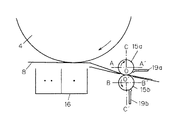
図2は本発明の構成を示したもので、一対の紙搬送ローラ15a、15bは転写部16直前に位置し、転写紙8の表面側すなわち感光体ドラム4に接する側に位置する紙搬送ローラの第1ローラ15aと反対側に位置する第2ローラ15bとからなる。第1ローラ15aと第2ローラ15bはそれぞれ体積抵抗が1×10¹⁰Ω・cm以上を有する材質で構成されていて、かつ転写紙8と第1ローラ15aの帯電極性が逆極で、転写紙8と第2ローラ15bの帯電極性が同極で、さらに第1ローラ15aと第2ローラ15bの帯電極性では第1ローラ15aが転写紙8と逆極性になるもので構成する。すなわち本実施例では、第1ローラ15aをポリアセタール(商品名ジュラコン)のプラスチックローラで、第2ローラ15bをエチレン−プロピレンのゴムローラで構成している。そして、第1ローラ15aと第2ローラ15bとはそれぞれ図中の矢印方向に互いに圧接しながら強制的に回転駆動されて、転写紙8を転写部16へと搬送するべく構成されている。
【0014】
したがって、本実施例では転写紙8が一対の紙搬送ローラ15a、15bを通過する時には、転写紙8は正極性の比較的低い帯電位に帯電し、第1ローラ15aは負極性の比較的高い帯電位に帯電し、第2ローラ15bは正極性の比較的高い帯電位に帯電する。その結果転写紙8の表面側に付着している正極性の紙粉は第1ローラ15a、第2ローラ15bおよび紙粉自身による上向きの電界により第1ローラ15aへと確実に静電吸着される。第1ローラ15aに吸着した紙粉はシート状の第1クリーニング部材19aによって第1ローラ15aの表面から分離され除去されるのである。
【0015】
なお、本実施例では第1ローラ15aをポリアセタール(商品名ジュラコン)のプラスチックローラで、第2ローラ15bをエチレン−プロピレンのゴムローラで構成しているが、複写装置の紙搬送ガイド板13、14の使用する材質により転写紙8の帯電極性が逆になった場合には第1ローラ15a、第2ローラ15bの材質を入れ換えるように設計すればよい。
【0016】
また、前述したように第1ローラ15aにはシート状の第1クリーニング部材19aが取り付けてあり、転写紙8の裏面にある紙粉は直接的には感光体4への影響を与えないが、第2ローラ15bに付着した若干の紙粉が第1ローラ15aに転移し、第1ローラ15aが紙粉で汚染するのを防止するためにシート状の第2クリーニング部材19bを取り付けてある。クリーニング部材19a、19bは厚さ1mm程度のシート状の非導電性の不織布(フェルトなど)であり、第1ローラ15a、第2ローラ15bにニップ幅(ローラとの接触幅)3mm程度確保できるよう押しつけて取り付けてある。クリーニング部材19a、19bで取り除かれた紙粉が溜り過ぎて擦り抜けないように、第1クリーニング部材19aは第1ローラ15aとはローラ中心を通る水平線より下にあると共に第1ローラ15aの中心を通る水平線よりも第1ローラ15aの回転下流側でかつ第1と第2ローラ接触点より回転上流側の位置に取り付けてあり、第2クリーニング部材19bは第2ローラ15bとは第2ローラ15b中心を通る水平線より下にあるとともに第2ローラ15bの中心より垂下した垂直軸線よりも回転下流側でかつ第2ローラ15b中心を通る水平線より回転上流側の位置に取り付けてある。これにより、薄いシートの取り付けとローラ自身の回転力利用という簡単な構成で、紙粉を除去するための十分なニップ幅を確保できるとともに、除去された紙粉が自重でニップ位置より吐き出され、取り除かれた紙粉が溜り過ぎないようにすることができる。
【0017】
【発明の効果】
以上詳述しましたように本発明は、転写紙から生じた紙粉を効率よく吸着して確実に転写紙表面および紙搬送ローラ表面から除去することができる。そのために、紙粉がクリーニングブレードのエッジと感光体表面の間に噛み込む量が激減し、クリーニング不良や感光体表面キズの発生をなくせることができ、さらにトナーリサイクルタイプの装置での紙粉混入による画像欠陥の発生を減らすことができ、安価で簡便なかつコンパクトな構成で使用者に長期間かつ高画質の画像を提供することができるといったような効果が得られる。
【図面の簡単な説明】
【図1】本発明の一実施例における電子写真複写装置に関する概略図
【図2】本発明の一実施例における電子写真複写装置に関する構成図
【符号の説明】
4 感光体ドラム
6 現像器
7 給紙カセット
8 転写紙
15 紙搬送ローラ
15a 第1ローラ
15b 第2ローラ
16 転写部
19a 第1クリーニング部材
19b 第2クリーニング部材[0001]
BACKGROUND OF THE INVENTION
The present invention relates to paper dust removal in paper conveyance of an electrophotographic copying apparatus.
[0002]
[Prior art]
Generally, in an electrophotographic copying apparatus, a transfer sheet is conveyed from a sheet feeding unit to a transfer unit. During that time, a sheet feeding roller, an intermediate roller, a registration roller, a sheet feeding guide plate, a conveyance guide plate, Paper dust is generated on the transfer paper surface and edges due to frictional contact.
[0003]
When such transfer paper with paper dust adhered is conveyed to the transfer section as it is, the paper dust is transferred to the surface of the photoconductor, and the paper dust accumulates between the edge of the cleaning blade and the photoconductor surface, resulting in poor cleaning. In the toner recycling type apparatus, paper dust is mixed into the developer by the toner collected from the cleaning unit, causing image defects, and the like.
[0004]
In order to solve such problems, conventionally, a cleaning member is attached only to the upper roller of the paper conveyance roller to remove paper dust adhering to the roller, or the upper roller of the paper conveyance roller is expensive to be bipolarly charged. A paper that has been used to remove paper dust using a charging roller has been proposed.
[0005]
[Problems to be solved by the invention]
However, in the above conventional configuration, since the cleaning member and the charging roller are attached only to the upper roller of the paper conveying roller corresponding to the upper surface of the transfer paper where the transfer paper contacts the photoconductor, the paper dust and the upper roller adhered to the lower roller. The paper powder transferred from the top was transferred again to the upper roller and could not be effectively removed. Further, an expensive charging roller having a small diameter bipolar charging tends to reduce the electric field effect for removing paper dust, and effective removal cannot be expected. In addition, with the method of pressing the paper dust cleaning member, it is not possible to expect an effective width of the cleaning nip, and it may accumulate between the roller and the cleaning member and rub away and cannot be effectively removed. Had.
[0006]
SUMMARY OF THE INVENTION An object of the present invention is to solve the above-described conventional problems, and to provide an electrophotographic copying apparatus capable of adsorbing and removing paper dust more reliably.
[0007]
[Means for Solving the Problems]
In order to solve this problem, the electrophotographic copying apparatus of the present invention includes a pair of paper transport rollers arranged on a transfer paper transport path from a paper feed section to a transfer section that transfers an image on a photoreceptor to the transfer paper surface side. When, and a sheet-like non-conductive cleaning member in contact with the respective pair of paper conveying rollers, the charge polarity of the first roller contacts the transfer sheet surface at the pair of sheet transport rollers when the paper conveyance The pair of paper transports so that the polarity of the transfer paper is opposite to that of the transfer paper and the charge polarity of the other second roller of the pair of paper transport rollers is the same as the polarity of the transfer paper charged during paper transport. Each of the rollers is made of a material having different non-conductivity .
[0008]
In addition, the sheet-like non-conductive first cleaning member that is pressed and disposed against the first roller has a contact point with the first roller at a point of contact with the first roller rather than a horizontal line passing through the center of the first roller. rotation at the downstream side and the an upstream side of the contact point of the pair of paper conveying rollers, before Symbol the second cleaning member of a sheet-like non-conductive contact disposed against the second roller and the second roller in the rotation downstream side of the second roller than the vertical axis of the contact point hanging down from the center of the second roller and, and is obtained by the rotation upstream side of the horizontal line passing through the center of the second roller.
[0009]
DETAILED DESCRIPTION OF THE INVENTION
According to a first aspect of the present invention comprises a pair of sheet conveying rollers disposed on the transfer sheet conveyance path from the paper feeding unit to the transfer unit for transferring an image on the photosensitive member to the transfer paper surface, the pair A sheet-like non-conductive cleaning member that contacts each of the paper transport rollers, and the charge polarity of the first roller that contacts the transfer paper surface side by the pair of paper transport rollers is charged when the paper is transported. Each of the pair of paper transport rollers so that the charging polarity of the other second roller of the pair of paper transport rollers is the same as the polarity of the transfer paper charged during paper transport. It is composed of materials having different non-conductivity . Thereby, the paper dust adhering to the transfer paper surface side is reliably electrostatically adsorbed to the first roller by the electric field generated by the first roller, the second roller and the paper dust itself, and the paper adsorbed to the first roller. The powder is separated and removed from the surface of the first roller by a sheet-like cleaning member. Therefore, it has an effect that the paper dust generated from the transfer paper can be efficiently adsorbed and reliably removed from the transfer paper surface.
[0010]
The invention according to
[0011]
Hereinafter, an embodiment of the present invention will be described with reference to the drawings. FIG. 1 shows an outline of the configuration of the electrophotographic copying apparatus. The outline of the operation of the apparatus will be described with reference to this figure.
[0012]
A document to be copied (hereinafter referred to as an original image) is placed on the
[0013]
FIG. 2 shows the configuration of the present invention. The pair of
[0014]
Therefore, in this embodiment, when the
[0015]
In this embodiment, the first roller 15a is composed of a polyacetal (trade name Duracon) plastic roller and the
[0016]
Further, as described above, the first roller 15a is provided with the sheet-like first cleaning member 19a, and the paper dust on the back surface of the
[0017]
【The invention's effect】
As described in detail above, the present invention can efficiently adsorb the paper dust generated from the transfer paper and reliably remove it from the transfer paper surface and the paper transport roller surface. As a result, the amount of paper dust that bites between the edge of the cleaning blade and the surface of the photoreceptor can be drastically reduced, eliminating the occurrence of poor cleaning and photoconductor surface scratches. It is possible to reduce the occurrence of image defects due to mixing, and to obtain an effect that a high-quality image can be provided for a long period of time to the user with an inexpensive, simple and compact configuration.
[Brief description of the drawings]
FIG. 1 is a schematic view of an electrophotographic copying apparatus according to an embodiment of the present invention. FIG. 2 is a block diagram of an electrophotographic copying apparatus according to an embodiment of the present invention.
4
Claims (2)
Priority Applications (1)
| Application Number | Priority Date | Filing Date | Title |
|---|---|---|---|
| JP09547797A JP3855352B2 (en) | 1997-04-14 | 1997-04-14 | Electrophotographic copying machine |
Applications Claiming Priority (1)
| Application Number | Priority Date | Filing Date | Title |
|---|---|---|---|
| JP09547797A JP3855352B2 (en) | 1997-04-14 | 1997-04-14 | Electrophotographic copying machine |
Publications (2)
| Publication Number | Publication Date |
|---|---|
| JPH10291670A JPH10291670A (en) | 1998-11-04 |
| JP3855352B2 true JP3855352B2 (en) | 2006-12-06 |
Family
ID=14138712
Family Applications (1)
| Application Number | Title | Priority Date | Filing Date |
|---|---|---|---|
| JP09547797A Expired - Lifetime JP3855352B2 (en) | 1997-04-14 | 1997-04-14 | Electrophotographic copying machine |
Country Status (1)
| Country | Link |
|---|---|
| JP (1) | JP3855352B2 (en) |
Families Citing this family (2)
| Publication number | Priority date | Publication date | Assignee | Title |
|---|---|---|---|---|
| JP3401520B2 (en) * | 1999-08-11 | 2003-04-28 | 京セラミタ株式会社 | Transfer method used for electrophotographic apparatus |
| JP4726745B2 (en) * | 2006-08-29 | 2011-07-20 | リコーエレメックス株式会社 | Conveyor / discharge device |
-
1997
- 1997-04-14 JP JP09547797A patent/JP3855352B2/en not_active Expired - Lifetime
Also Published As
| Publication number | Publication date |
|---|---|
| JPH10291670A (en) | 1998-11-04 |
Similar Documents
| Publication | Publication Date | Title |
|---|---|---|
| US4750018A (en) | Pre-transfer copy sheet cleaning apparatus | |
| JPS62153849A (en) | Method and machine for copying book | |
| US4302093A (en) | Combined transfer and registration system for electrophotographic copier | |
| US4533235A (en) | Cleaning device for use in an image forming apparatus | |
| US4899198A (en) | Dual purpose cleaning apparatus | |
| JP3231486B2 (en) | Cleaning equipment | |
| JP2001175142A (en) | Device for removing particle from non-image forming surface of photoreceptor belt | |
| JP3855352B2 (en) | Electrophotographic copying machine | |
| JPS59133566A (en) | Paper powder removing device | |
| JP3576894B2 (en) | Sheet member conveying device in image forming apparatus | |
| JP3839969B2 (en) | Image forming apparatus | |
| JP2630785B2 (en) | Image forming method for electrostatic recording device | |
| JPS6221691B2 (en) | ||
| JP2001142366A (en) | Image forming device and its cleaning method | |
| JPS63289574A (en) | Cleaning device | |
| JP2006308629A (en) | Image forming apparatus | |
| JPH11265136A (en) | Cleaner | |
| JP3256000B2 (en) | Image forming device | |
| JPS6139420Y2 (en) | ||
| JPH05107993A (en) | Image forming device | |
| JP2002154699A (en) | Image forming device | |
| JPH05165375A (en) | Cleaning device for carrying roller | |
| JP3418117B2 (en) | Image forming device | |
| JPS63142364A (en) | Electrophotographic printer | |
| JPH01312577A (en) | Cleaning device for image forming device |
Legal Events
| Date | Code | Title | Description |
|---|---|---|---|
| A621 | Written request for application examination |
Free format text: JAPANESE INTERMEDIATE CODE: A621 Effective date: 20040216 |
|
| RD01 | Notification of change of attorney |
Free format text: JAPANESE INTERMEDIATE CODE: A7421 Effective date: 20040312 |
|
| RD01 | Notification of change of attorney |
Free format text: JAPANESE INTERMEDIATE CODE: A7421 Effective date: 20050623 |
|
| A977 | Report on retrieval |
Free format text: JAPANESE INTERMEDIATE CODE: A971007 Effective date: 20060130 |
|
| A131 | Notification of reasons for refusal |
Free format text: JAPANESE INTERMEDIATE CODE: A131 Effective date: 20060328 |
|
| A521 | Written amendment |
Free format text: JAPANESE INTERMEDIATE CODE: A523 Effective date: 20060523 |
|
| TRDD | Decision of grant or rejection written | ||
| A01 | Written decision to grant a patent or to grant a registration (utility model) |
Free format text: JAPANESE INTERMEDIATE CODE: A01 Effective date: 20060822 |
|
| A61 | First payment of annual fees (during grant procedure) |
Free format text: JAPANESE INTERMEDIATE CODE: A61 Effective date: 20060904 |
|
| FPAY | Renewal fee payment (event date is renewal date of database) |
Free format text: PAYMENT UNTIL: 20090922 Year of fee payment: 3 |
|
| FPAY | Renewal fee payment (event date is renewal date of database) |
Free format text: PAYMENT UNTIL: 20100922 Year of fee payment: 4 |
|
| FPAY | Renewal fee payment (event date is renewal date of database) |
Free format text: PAYMENT UNTIL: 20110922 Year of fee payment: 5 |
|
| FPAY | Renewal fee payment (event date is renewal date of database) |
Free format text: PAYMENT UNTIL: 20120922 Year of fee payment: 6 |