JP3854860B2 - Conductive ball mounting device - Google Patents
Conductive ball mounting device Download PDFInfo
- Publication number
- JP3854860B2 JP3854860B2 JP2001379093A JP2001379093A JP3854860B2 JP 3854860 B2 JP3854860 B2 JP 3854860B2 JP 2001379093 A JP2001379093 A JP 2001379093A JP 2001379093 A JP2001379093 A JP 2001379093A JP 3854860 B2 JP3854860 B2 JP 3854860B2
- Authority
- JP
- Japan
- Prior art keywords
- flux
- package
- pin
- supply jig
- cleaning
- Prior art date
- Legal status (The legal status is an assumption and is not a legal conclusion. Google has not performed a legal analysis and makes no representation as to the accuracy of the status listed.)
- Expired - Fee Related
Links
Images


Description
【0001】
【発明の属する技術分野】
本発明は、BGA(Ball Grid Array)、CSP(Chip Size Package、又は、Chip Scale Package)など、導電性の突出接点(以下、バンプという)を実装基板との接続材として用いるパッケージの接続端子に、前記バンプを形成するための導電性ボールを搭載する導電性ボールの搭載装置に関するものである。
【0002】
【従来の技術】
LSIを用いた半導体パッケージのように、入出力端子の数が多いパッケージを実装基板へ接続するための構造として、パッケージ側へバンプを形成する構造が採用されている。このバンプは、パッケージの接続端子に搭載した導電性ボール(例えば、はんだボールに代表される導電性ボール、以下、はんだボールという)を加熱溶解することにより形成される。
【0003】
前記はんだボールをパッケージの接続端子へ搭載する方法の一つとして、予め、前記パッケージの接続端子にフラックスを塗布した後、該フラックスの上にはんだボールを供給する方法がある。この方法において使用されるフラックス供給治具は、前記パッケージの接続端子の配列と同じ配列で配置され、かつ、その軸方向に移動可能な複数のピンを有し、このピンの先端に付着させたフラックスをパッケージの接続端子に転写するようになっている。
【0004】
前記フラックス供給治具1は、図9に示すように、パッケージの接続端子の配列と同じ配列で複数の穴が形成された本体2と、本体2の穴と連通し、該穴より小径の複数の穴が形成された底板3と、カバー5とを有し、前記本体2と底板3の穴に摺動可能に嵌合する複数のピン6と、各ピン6を付勢するばね7を備えている。
【0005】
そして、ピン6にフラックスを付着させるとき、あるいは、パッケージの接続端子にフラックスを転写させるときに、ピン6先端がフラックス供給装置や接続端子と接触したとき、その接触圧が高くなると、ばね7を圧縮しながらピン6がその軸方向に移動して、接触圧の軽減を図るようになっている。
【0006】
【発明が解決しようとする課題】
図10(a)に示すように、フラックス供給治具1のピン6の先端に付着させたフラックス9を、パッケージの接続端子に転写した場合、図10(b)に示すように、ピン6の先端に微量のフラックス9が残る(フラックス9の粘度が高いものほど残る量が多くなる)。そして、繰り返しフラックス9の供給を行なうと、ピン6の先端に残留するフラックス9の量が次第に多くなり、図10(c)に示すように、ピン6の先端が次第に太くなって、付着するフラックス9の量も増加することになる。
【0007】
さらにフラックス9の供給を続けると、図11(a)、(b)に示すように、パッケージ10の接続端子11に供給されるフラックス9の量が増加して、隣接する接続端子11間でフラックス9が繋がるようになる。このような状態で、フラックス9の上にはんだボールを搭載してリフローすると、リフロー時に、図11(c)に示すように、フラックス9上に搭載されたはんだボール12が移動して、バンプの位置がずれたり、隣接したはんだボール12が合体する等バンプ不良が発生する。
【0008】
また、パッケージの接続端子の数が増加して、接続端子間の寸法が狭く(例えば、0.5mm)なると、そこに搭載するはんだボールの直径も小さく(例えば、0.3mm)なる。従って、パッケージの接続端子にフラックスを供給するためのフラックス供給治具におけるピンの間隔も接続端子と同様に狭い間隔になる。このように、ピンの間隔が狭くなると、フラックスの供給を繰り返すことにより、ピンの先端に残留するフラックスの量が少なくても、図12に示すように、ピン6に付着させたフラックス9が繋がってしまうことがある。
【0009】
このような状態で、パッケージにフラックスの供給を行なうと、図13(a)に示すように、パッケージ10の隣接する接続端子11、11に供給されたフラックス9が繋がった状態になる。この状態で、フラックス9上にはんだボール12を搭載してリフローすると、リフロー時に、図13(b)に示すように、フラックス9上に搭載されたはんだボール12が移動して、隣接したはんだボール12が合体してバンプ不良が発生する。
【0010】
また、パッケージの接続端子の間隔が小さくなると、フラックス供給治具に使用し得るピンの径も細くなる。このため、ピンの強度を確保するように、ピンの長さを短くすると、ピンがその軸方向に摺動したときに、ピンに残留しているフラックスが底板の穴の内周面とピンの外周面との間に押し込まれることがある。また、ピンの先端に残留するフラックスを圧縮空気の吹付け等により除去しようとすると、図14に示すように、圧縮空気の流れによって、底板3の穴とピン6の間にフラックス9の破片が侵入して、ピン6の動きが鈍くなったり、あるいは動かなくなったりする。
【0011】
そして、ピンが動かなくなった状態でパッケージにフラックスを転写した場合、図15(a)に示すように、ピン6と接続端子11の接触圧が大きくなってパッケージ10を破損したり、図15(b)に示すように、ピン6が折れ曲がたり、あるいは、図15(c)に示すように、ピン6が上昇した位置で止まってしまい、接続端子11にフラックスを転写できないなどの不具合が発生する。
【0012】
上記のように、パッケージの接続端子にフラックス供給治具でフラックスを供給し、該フラックスの上にはんだボールを搭載してバンプを形成するものにおいては、フラックスを供給したときピンに残るフラックスが堆積して、バンプ不良の原因となったり、ピンに付着し残留したフラックスにより種々の不具合が発生する。
【0013】
上記の事情に鑑み、本発明は、フラックス供給装置のピンに残留するフラックスにより発生する種々の不具合をなくすようにした導電性ボールの搭載装置を提供することを目的とする。
【0014】
【課題を解決するための手段】
上記の目的を達成するため、本発明の請求項1においては、複数の接続端子(11)が形成されたパッケージ(10)を位置決めする位置決め手段(30)と、複数の導電性ボール(12)を収容した導電性ボール供給手段(77)と、前記パッケージ(10)に形成された複数の接続端子(11)と同じ配列で吸着穴(81)が形成され、前記導電性ボール供給手段(77)から前記吸着穴(81)に導電性ボール(12)を吸着して取出し、前記パッケージ(10)の接続端子(11)上に供給する整列マスク(80)と、所定の厚さのフラックス膜を形成し、フラックス(9)を供給するフラックス供給手段(61)と、前記パッケージ(10)に形成された複数の接続端子(11)と同じ配列で、その軸方向に摺動可能に配置された複数のピン(72)を備え、前記フラックス供給手段(61)で前記ピン(72)の先端に付着させたフラックス(9)を、前記パッケージ(10)の接続端子(11)上に供給するフラックス供給治具(66)と、該フラックス供給治具のすべてのピンを収容し得る洗浄槽(92,102)を有し、該洗浄槽の中で、前記ピン(72)の先端に付着したフラックスを、該フラックスに対する溶剤からなる洗浄液により洗い落とす洗浄装置(90,100)と、を備えた、
ことを特徴とする、導電性ボール搭載装置にある。
【0015】
また、本発明の請求項2においては、前記フラックス供給治具(66)は、内部に圧縮ガスが流入する空間(67)が形成され、該圧縮ガスを前記フラックス供給治具(66)とピン(72)の隙間から外部に向けて流出させるようにした、
ことを特徴とする、請求項1記載の導電性ボール搭載装置にある。
【0016】
また、本発明の請求項3においては、前記洗浄装置(90)が、前記フラックス供給治具(66)のピン(72)の先端を前記フラックス(9)に対する溶剤からなる洗浄液(96)中に浸漬し、超音波振動を与えるようにした超音波洗浄装置で構成されている、
ことを特徴とする、請求項1記載の導電性ボール搭載装置にある。
【0017】
また、本発明の請求項4においては、前記洗浄装置(100)が、前記フラックス供給治具(66)のピン(72)の先端に、前記フラックス(9)に対する溶剤からなる洗浄液(96)を吹き付ける噴射装置である、
ことを特徴とする請求項1記載の導電性ボールの搭載装置にある。
【0018】
なお、括弧内の符号等は、図面における対応要素を示す便宜的なものであり、従って、本記述は、図面上の記載に限定拘束されるものではない。
【0019】
【発明の実施の形態】
以下、本発明の実施の形態を図面に基づいて説明する。図1ないし図7は、本発明の実施の形態を示すもので、図1は、本発明を適用する導電性ボールの搭載装置の斜視図、図2は、フラックス供給治具の洗浄装置を示す断面図、図3は、フラックス供給治具の拡大断面図、図4は、はんだボール供給手段とマスクの関係を示す正面図、図5は、フラックス供給治具のピンにフラックスを付着させる工程を示す工程図、図6は、パッケージにフラックスを転写させる工程を示す工程図、図7は、パッケージにはんだボールを搭載する工程を示す工程図である。
【0020】
図1において、導電性ボールの搭載装置15は、ベース16に配置され、はんだボール12を搭載するパッケージ10の供給と排出を行なう搬送部17と、パッケージの位置決めを行なうマウント部30と、後述するフラックス供給治具とマスクを移動させる駆動部36と、マウント部30で位置決めされたパッケージ10にフラックス9を供給するフラックス供給部60と、フラックス9が塗布されたパッケージ10の接続端子11上にはんだボール12を搭載するはんだボール搭載部76と、搭載位置に位置決めされたパッケージ10の接続端子11の位置を検出する検出部85と、フラックス供給治具66のピン72を洗浄するための洗浄装置90(図2参照)を有している。
【0021】
前記搬送部17は、ベース16の上面を矢印X方向(図1の左右方向)に貫通する溝19の両端部の上部に、溝19を横切るように回転可能に支持された一対の軸20を備え、該軸20の両端にはそれぞれ一対のプーリ21が固定され、該プーリ21には、前記溝19の長手方向(矢印X方向)と平行にベルト22が掛け渡されている。そして、前記軸20の一方は、前記ベース16に固定されたモータ23に結合され駆動される。
【0022】
また、搬送部17は、複数のパッケージ10を載置するキャリア25を有し、このキャリア25を前記ベルト22上に載置して、パッケージ10の矢印X方向への搬送を行なう。前記溝19内には、前記キャリア25の移動経路の下方に位置するようにシリンダ26が配置されている。このシリンダ26には、前記キャリア25の移動経路に対し進退可能なストッパ27が取付けられている。
【0023】
従って、ベルト22上にキャリア25を載置して、モータ23を作動させることにより、キャリア25を矢印X方向に搬送することが出来る。また、このとき、シリンダ26の作動により、ストッパ27をキャリア25の移動経路中に突出させておくと、キャリア25をストッパ27に当接させて、停止させることが出来る。
【0024】
前記マウント部30は、前記溝19の下方に位置し、矢印X方向に移動可能なスライド部材を有する直線案内手段31と、ねじ送り機構(図示せず)を介して前記スライド部材を駆動するモータ32を備えている。そして、前記スライド部材には、可動部材が前記溝19の底面を矢印X方向と矢印Z方向(図面の上下方向)に摺動可能に貫通するようにシリンダ33が固定され、このシリンダ33の可動部材には、載置台35が固定されている。
【0025】
従って、シリンダ33を作動させて載置台35を上昇させることにより、前記ストッパ27で停止させられたキャリア25を、ベルト22から上方の搭載位置へ移動させることが出来る。また、モータ32を作動させることにより、キャリア25上のパッケージ10の配置間隔分を順次移動させ、キャリア25に配置されたパッケージ10を順次搭載位置へ移動させることが出来る。
【0026】
前記駆動部36は、前記溝19を跨ぐように、ベース16の矢印X方向の両端部に、所定の間隔で平行に固定された一対のコラム37を備えている。これらのコラム37の上端面には、それぞれ直線案内装置を構成するレール39が、所定の間隔で平行に固定されている。また、一方のコラム37の上端面には、軸受40を介して、レール39と所定の間隔で平行にボールねじ41が回転可能に支持されている。そして、このボールねじ41の一端は、コラム37に固定されたモータ42に連結されている。
【0027】
スライダ43は、前記レール39に摺動可能に嵌合するベアリング(図示せず)と、前記ボールねじ41と螺合するナット(図示せず)を備え、前記モータ42の作動により、レール39に沿って矢印Y方向(図1の紙面の前後方向)に移動する。このスライダ43の正面には、その上下に所定の間隔で平行に、矢印X方向に延び、直線案内装置を構成する一対のレール45が固定されている。また、スライダ43の正面には、軸受46を介して、前記レール45の間に位置するように、レール45と所定の間隔で平行にボールねじ47が回転可能に支持されている。そして、このボールねじ47の一端は、スライダ43に固定されたモータ49に連結されている。
【0028】
スライドプレート50は、前記レール45に摺動可能に嵌合するベアリング(図示せず)と、前記ボールねじ47に螺合するナット(図示せず)を備え、前記モータ49の作動により、レール45に沿って矢印X方向に移動する。このスライドプレート50の正面には、所定の間隔で平行に、矢印Z方向に延び、直線案内装置を構成する一対のレール51が固定されている。また、スライドプレート50の正面には、軸受52を介して、前記レール51の間に位置するように、レール51と所定の間隔で平行にボールねじ53が回転可能に支持されている。そして、このボールねじ53の一端は、スライドプレート50に固定されたモータ55に連結されている。
【0029】
マウントヘッド56は、前記レール51に摺動可能に嵌合するベアリング57と、前記ボールねじ53に螺合するナット(図示せず)を備え、前記モータ55の作動により、レール51に沿って矢印Z方向に移動する。
【0030】
従って、駆動部36は、モータ42、モータ49及びモータ55を作動させることにより、マウントヘッド56を矢印X、Y、Z方向の任意の位置へ移動させることが出来る。
【0031】
前記フラックス供給部60は、前記ベース16に支持されたフラックス供給手段61と、前記マウントヘッド56に支持されたフラックス供給治具66からなる。
【0032】
前記フラックス供給手段61は、図1及び図2に示すように、ばね62で支えられ、内部に平面が形成されたフラックス容器63と、このフラックス容器63内に供給されたフラックス9を掻き均すスキージ65を備えている。そして、前記スキージ65を前記フラックス容器63の平面と所定の間隔で対向させ、矢印X方向に移動させて、フラックス容器63内に供給されたフラックス9を掻き均すことにより、フラックス9の膜を形成する。
【0033】
前記フラックス供給治具66は、図3に示すように、前記パッケージ10の接続端子11の配列と同じ配列で複数の穴が形成され、かつ底面に座繰りによる空間67が形成された本体69と、本体69の穴と連通し、該穴より小径の複数の穴が形成された底板70と、カバー71とを有し、前記本体69と底板70の穴に摺動可能に嵌合する段付きの複数のピン72と、各ピン72を底板70から突出するよう付勢する複数のばね73を備えている。
【0034】
そして、本体69、底板70及びカバー71を一体に固定することにより、底板70の穴と連通する空間67を形成し、該空間67を圧縮空気供給源75に接続している。従って、圧縮空気供給源75から空間67に供給された圧縮空気は、底板70の穴の内周面と、ピン72の外周面との隙間を通り大気中へ流出する。この圧縮空気の流れによって、底板70の穴とピン72の隙間にフラックス9が侵入するのを防ぎ、ピン72の円滑な移動を維持することが出来る。
【0035】
前記はんだボール搭載部76は、前記ベース16に支持されたはんだボール供給手段77と、前記マウントヘッド56に支持され、はんだボール12を吸着して保持する整列マスク80からなる。
【0036】
前記はんだボール供給手段77は、前記ベース16上に配置され、複数のはんだボール12を収納するはんだボール容器79と、このはんだボール容器79内ではんだボール12を浮遊させるための加振手段(図示せず)もしくは圧縮空気の噴出手段(図示せず)を備えている。
【0037】
前記整列マスク80は、図4に示すように、中空の箱形に形成され、その下面にパッケージ10の接続端子11の配列と同じ配列で複数の吸着穴81が形成されている。この吸着穴81の径は、パッケージ10に搭載すべきはんだボール12の直径より小さくなっている。また、この整列マスク80は、配管82により真空供給源83に接続されている。
【0038】
従って、整列マスク80を、はんだボール容器79の開口部を覆うように配置して、整列マスク80に真空圧を供給すると共に、はんだボール容器79に振動を与えて内部に収納したはんだボール12を浮遊させる。すると、はんだボール12が、はんだボール容器79の底から整列マスク80の底面に向けて浮遊するため、浮遊したはんだボール12は、吸着穴81から吸引される空気の流れによって吸着穴81に引きつけられ、吸着保持される。
【0039】
前記検出部85は、図1に示すように、マウントヘッド56に取付けられたリングライト86と、CCDカメラ87を備えている。そして、CCDカメラ87の撮影画像を画像解析装置(図示せず)で解析して、パッケージ10の接続端子11の位置を演算する。
【0040】
前記洗浄装置90は、前記マウントヘッド56の移動によって移動するフラックス供給治具66の移動領域内で、搭載作業の邪魔にならないようにベース16上の適宜位置に配置されている。そして、図2に示すように、ベース16上に立設された支柱91で支持された洗浄槽92と、この洗浄槽92の底面に固定された超音波振動源93と、この超音波振動源93を振動させるための電源95を備えている。
【0041】
そして、洗浄槽92内に所要量の洗浄液96(フラックスの溶剤、例えば、水、アルコール等)を入れ、この洗浄液96内にフラックス供給治具66のピン72を浸漬して、電源95により超音波振動源93を振動させることにより、ピン72の洗浄を行なう。
【0042】
なお、洗浄液96として、アルコールなどの有機溶剤を使用する場合には、洗浄装置90にカバー(図示せず)を設けるほか、局所排気ダクト(図示せず)を設置して、職場内への有機溶剤の蒸気の拡散を防止する。
【0043】
このような構成で、導電性ボール搭載装置1は、パッケージ10を搭載したキャリア25が、図1の左側から搬送部17のベルト22上に供給されると、シリンダ26が作動してストッパ27を上昇させる。すると、モータ23が作動して、ベルト22を走行させ、キャリア25を図1の左側から右側に向けて矢印X方向に搬送する。そして、キャリア25がストッパ27に当接すると、キャリア25はその位置に停止させられる。キャリア25の搬送が終了すると、モータ23が停止してベルト22の走行も停止する。すると、シリンダ26が作動して、ストッパ27を下降させる。
【0044】
マウント部30のシリンダ33が作動して、載置台35を上昇させ、ベルト22上に載置されているキャリア25を載置台35で押し上げ、キャリア25に載置されているパッケージ10を搭載位置に位置決めする。一方、フラックス供給手段61では、スキージ65を移動させて、フラックス容器63内のフラックス9を掻き均し、フラックス9の薄い膜を形成する。
【0045】
駆動部36では、モータ42、モータ49及びモータ55を作動させ、マウントヘッド56を矢印X、Y、Z方向に移動させて、フラックス供給治具66と整列マスク80をそれぞれフラックス供給容器63とはんだボール容器79に侵入させる。すると、フラックス供給治具66のピン72は、図5に示すように、フラックス容器63内に形成されたフラックス9の薄い膜内に侵入し、ピン72の先端に所要量のフラックス9を付着させる。
【0046】
一方、整列マスク80は、図4に示すように、はんだボール容器79の開口部を覆い、真空供給源83から配管82を通して真空圧が供給される。同時に、はんだボール容器79が加振され、中に収納されたはんだボール12が浮遊する。所要の時間経過すると、整列マスク80の全ての吸着穴79にはんだボール12が吸着される。
【0047】
すると、駆動部36のモータ42、モータ49及びモータ55が作動してマウントヘッド56を矢印X、Y、Z方向に移動させ、CCDカメラ87を搭載位置にあるパッケージ10と対向する位置へ移動させる。そして、リングライト86を点灯し、CCDカメラ87でパッケージ10を撮影する。画像解析装置は、撮影された画像データから接続端子11の像を抽出すると共に、その位置を演算して、その演算結果を制御装置(図示せず)へ送る。
【0048】
制御装置は、画像解析装置から入力されたパッケージ10の接続端子11の位置データに基づき、駆動部36のモータ42及びモータ49を作動させ、フラックス供給治具66のピン72をパッケージ10の接続端子11と対向する位置へ移動させる。すると、モータ55を作動して、マウントヘッド56を下降させ、図6に示すように、フラックス供給治具66のピン72をパッケージ10の接続端子11に接触させ、ピン72に付着したフラックス9を接続端子11に転写供給する。このとき、ピン72と接続端子11の接触圧が高くなると、ピン72がばね73を圧縮しながらフラックス供給治具66に対して相対的に上昇して、接触圧の異常な上昇を防止する。
【0049】
フラックス9の供給が終わると、モータ55の作動によりマウントヘッド56を所定の位置まで上昇させた後、モータ42及びモータ49を作動させて、図7に示すように、整列マスク80に吸着保持したはんだボール12を、フラックス9が供給されたパッケージ10の接続端子11と対向させる。そして、モータ55を作動させて、はんだボール12が接続端子11と接触する位置までマウントヘッド56を下降させる。
【0050】
モータ55を停止させた後、整列マスク80に供給されている真空圧を遮断し、整列マスク80内を大気圧に連通させる。すると、整列マスク80による吸着力が解放され、はんだボール12は整列マスク80から解放される。この状態で、モータ55が作動してマウントヘッド56を上昇させると、はんだボール12は、フラックス9の粘着力によって接続端子11上に残り、整列マスク80からパッケージ10の接続端子11へ搭載される。
【0051】
マウントヘッド56が上昇すると、マウント部30のモータ32が作動して、載置台35をキャリア25に載置されたパッケージ10の載置間隔分だけ移動させ、次のパッケージ10を搭載位置へ移動させる。
【0052】
このような操作を繰り返すことにより、キャリア25上に載置された全てのパッケージ10にはんだボール12が搭載されると、マウント部30のシリンダ33が作動して、載置台35を下降させ、キャリア25を搬送部17のベルト22上に載置する。すると、モータ23が作動してベルト22を走行させ、キャリア25を図1の右側に向けて搬送し排出する。
【0053】
上記のような操作を繰り返すことにより、順次パッケージ10にはんだボール12の搭載を行なう。すると、フラックス供給治具66のピン72の先端には、フラックス9をパッケージ10に転写した際に、パッケージ10側に転写しきれずにピン72に残留したフラックス9が徐々に溜まり、ピン72の先端が次第に太くなってくる。
【0054】
このため、所定回数のフラックス9の供給を行なうごとに(又は、所定時間作業を継続したとき)、フラックス供給治具66を洗浄装置90へ移動させ、ピン72の先端を洗浄液96内に浸漬した状態で、電源95を作動させ、超音波振動源93により洗浄液96に振動を与えて、ピン72の先端に付着したフラックスを洗浄除去する。所定時間の洗浄を行なった後、ピン72を乾燥させ、はんだボール12の搭載作業を再開する。
【0055】
このとき、フラックス供給治具66に圧縮空気を供給し、底板70の穴とピン72に隙間から圧縮空気を噴出させることにより、フラックスを溶解した洗浄液の飛沫が前記隙間に入るのを防止することが出来る。噴出させる圧縮空気は、例えば、底板70の穴とピン72の隙間が、片側0.015mmの場合、フラックス供給治具66に供給する圧縮空気は、圧力、4〜5kg/cm2、流量、5l/min程度に設定する。なお、圧縮空気の供給量は前記例示の範囲に限らず、使用するピンの太さや数によって適宜設定する。
【0056】
図8は、洗浄装置の他の実施の形態を示す断面図である。
【0057】
同図において、図2と同じものは同じ符号を付けて示してある。この洗浄装置100は、支柱101を介してベース16上に配置された洗浄槽102と、この洗浄槽102内に配置された複数のノズル103とを備えている。このノズル103は、洗浄液供給装置105に接続されている。また、前記洗浄槽102の底面には、複数の穴が形成され、この穴を介して吸引装置106に接続されている。
【0058】
このような構成で、洗浄槽102の上部の開口部を覆うようにフラックス供給治具66を配置した後、洗浄液供給装置105を作動させ、ノズル103からピン72に向けて洗浄液を、例えば、圧力、0.5〜1.0kg/cm2で、30〜60秒間(なお、吹きつけ圧力と時間は、予め実験等で確認し、設定する)吹き付けると共に、吸引装置106を作動させて、洗浄槽102の底に溜まる洗浄液を洗浄槽102から排出し回収する。この洗浄液の吹き付けにより、ピン72に付着したフラックスを除去する。
【0059】
洗浄装置100をこのような構成にしても、前記実施形態と同様の効果を得ることが出来る。
【0060】
なお、前記各実施形態において、前記洗浄液は、フラックス供給治具66を洗浄するたびに交換するようにしてもよいし、繰り返し使用するようにしてもよい。繰り返し使用する場合には、フラックス供給治具66を洗浄するたびに、洗浄液内のフラックスの濃度が上がるので、予め実験等により使用可能な洗浄回数を決めておき、その洗浄回数に達したら洗浄液を交換することが必要である。
【0061】
【発明の効果】
以上述べたように、本発明によれば、フラックス供給治具のピンに付着したフラックスを洗い落とす洗浄装置を設け、はんだボールの搭載作業中定期的(所定回数ごと、又は、所定時間ごと)に、フラックス供給治具のピンを洗浄するようにしたので、パッケージの接続端子に対するフラックスの供給量が安定し、リフロー時に、隣接するはんだボールが合体する等の不具合の発生を防止することが出来る。また、フラックス供給治具に対するピンの移動を円滑に保つことが出来、ピンの動きの悪さに起因する不具合を防止することが出来る。
【図面の簡単な説明】
【図1】本発明を適用する導電性ボールの搭載装置の斜視図。
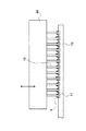
【図2】フラックス供給治具の洗浄装置を示す断面図。
【図3】フラックス供給治具の拡大断面図。
【図4】はんだボール供給手段とマスクの関係を示す正面図。
【図5】フラックス供給治具のピンにフラックスを付着させる工程を示す工程図。
【図6】パッケージにフラックスを転写させる工程を示す工程図。
【図7】パッケージにはんだボールを搭載する工程を示す工程図。
【図8】フラックス供給治具の洗浄装置の他の実施の形態を示す断面図。
【図9】従来のフラックス供給治具を示す断面図。
【図10】フラックス供給治具のピンとフラックスの関係を示し、(a)は、ピンにフラックスを付着させた状態を示す拡大図、(b)は、パッケージへフラックスを転写した後、フラックスがピンに残留した状態を示す拡大図、(c)は、ピンに残留したフラックスが蓄積された状態を示す拡大図。
【図11】パッケージに転写されたフラックスの状態を示し、(a)は、平面から見た拡大図、(b)は、側面から見た拡大図、(c)は、(a)、(b)の状態ではんだボールを搭載し、リフローしたときのはんだボールの挙動を示す拡大図。
【図12】フラックス供給治具のピンとフラックスの関係を示し、フラックス供給治具のピン間でフラックスが繋がった状態を示す拡大図。
【図13】パッケージに転写されたフラックスの状態を示し、(a)は、図12の状態でパッケージにフラックスを転写したときの状態を示す拡大図、(b)は、(a)の状態ではんだボールを搭載しリフローしたときのはんだボールの挙動を示す拡大図。
【図14】従来のフラックス供給治具におけるピンと治具の隙間にフラックスが侵入した状態を示す拡大図。
【図15】フラックス供給治具のピンとパッケージの関係を示し、(a)は、パッケージを破損した状態を示す拡大図、(b)は、フラックス供給治具でピンに曲がりが発生した状態を示す拡大図、(c)は、フラックス供給治具のピンが動かなくなった状態を示す拡大図。
【符号の説明】
9…フラックス
10…パッケージ
11…接続端子
12…導電性ボール(はんだボール)
30…位置決め手段(マウント部)
61…フラックス供給手段
66…フラックス供給治具
67…空間
72…ピン
77…導電性ボール供給手段(はんだボール供給手段)
80…整列マスク
81…吸着穴
90…洗浄装置
96…洗浄液
100…洗浄装置[0001]
BACKGROUND OF THE INVENTION
The present invention provides a connection terminal for a package that uses a conductive protruding contact (hereinafter referred to as a bump) as a connecting material to a mounting substrate, such as BGA (Ball Grid Array), CSP (Chip Size Package), or Chip Scale Package (CSP). The present invention relates to a conductive ball mounting apparatus for mounting a conductive ball for forming the bump.
[0002]
[Prior art]
A structure in which bumps are formed on the package side is employed as a structure for connecting a package having a large number of input / output terminals to a mounting substrate, such as a semiconductor package using LSI. This bump is formed by heating and melting a conductive ball (for example, a conductive ball represented by a solder ball, hereinafter referred to as a solder ball) mounted on a connection terminal of the package.
[0003]
As one method for mounting the solder balls on the connection terminals of the package, there is a method in which a flux is previously applied to the connection terminals of the package and then the solder balls are supplied onto the flux. The flux supply jig used in this method is arranged in the same arrangement as the arrangement of the connection terminals of the package, and has a plurality of pins movable in the axial direction, and is attached to the tip of the pins. The flux is transferred to the connection terminal of the package.
[0004]
As shown in FIG. 9, the
[0005]
When the flux is attached to the
[0006]
[Problems to be solved by the invention]
As shown in FIG. 10A, when the
[0007]
When the supply of the
[0008]
Further, when the number of connection terminals of the package increases and the dimension between the connection terminals becomes narrow (for example, 0.5 mm), the diameter of the solder ball mounted thereon also becomes small (for example, 0.3 mm). Therefore, the distance between the pins in the flux supply jig for supplying flux to the connection terminal of the package is narrow as in the case of the connection terminal. As described above, when the pin interval is narrowed, the
[0009]
When flux is supplied to the package in such a state, the
[0010]
Moreover, if the space | interval of the connection terminal of a package becomes small, the diameter of the pin which can be used for a flux supply jig will also become thin. For this reason, if the length of the pin is shortened so as to ensure the strength of the pin, when the pin slides in the axial direction, the flux remaining on the pin will be in contact with the inner peripheral surface of the hole in the bottom plate and the pin. It may be pushed between the outer peripheral surfaces. Further, if the flux remaining at the tip of the pin is to be removed by blowing compressed air or the like, as shown in FIG. 14, fragments of the
[0011]
When the flux is transferred to the package in a state where the pins are not moved, the contact pressure between the
[0012]
As described above, when flux is supplied to the connection terminals of the package with a flux supply jig, and solder balls are mounted on the flux to form bumps, the flux remaining on the pins is deposited when the flux is supplied. As a result, various defects are caused by the defective flux due to the defective bumps or attached to the pins.
[0013]
In view of the above circumstances, an object of the present invention is to provide a conductive ball mounting device that eliminates various problems caused by flux remaining on pins of a flux supply device.
[0014]
[Means for Solving the Problems]
In order to achieve the above object, in
The conductive ball mounting apparatus is characterized by the above.
[0015]
According to a second aspect of the present invention, the flux supply jig (66) is formed with a space (67) into which compressed gas flows, and the compressed gas is supplied to the flux supply jig (66) and a pin. (72) It was made to flow toward the outside through the gap.
The conductive ball mounting apparatus according to
[0016]
According to a third aspect of the present invention, the cleaning device (90) includes the tip of the pin (72) of the flux supply jig (66) in a cleaning liquid (96) made of a solvent for the flux (9). It is composed of an ultrasonic cleaning device soaked and applied with ultrasonic vibration.
The conductive ball mounting apparatus according to
[0017]
According to a fourth aspect of the present invention, the cleaning device (100) applies a cleaning liquid (96) made of a solvent for the flux (9) to the tip of the pin (72) of the flux supply jig (66). Spraying device to spray,
The conductive ball mounting apparatus according to
[0018]
In addition, the code | symbol etc. in a parenthesis is a thing which shows the corresponding element in drawing for convenience, Therefore Therefore, this description is not restrict | limited to the description on drawing.
[0019]
DETAILED DESCRIPTION OF THE INVENTION
Hereinafter, embodiments of the present invention will be described with reference to the drawings. 1 to 7 show an embodiment of the present invention. FIG. 1 is a perspective view of a conductive ball mounting apparatus to which the present invention is applied. FIG. 2 shows a flux supply jig cleaning apparatus. 3 is an enlarged cross-sectional view of the flux supply jig, FIG. 4 is a front view showing the relationship between the solder ball supply means and the mask, and FIG. 5 is a process of attaching the flux to the pins of the flux supply jig. FIG. 6 is a process diagram showing a process of transferring flux to the package, and FIG. 7 is a process chart showing a process of mounting solder balls on the package.
[0020]
In FIG. 1, a conductive
[0021]
The
[0022]
The
[0023]
Therefore, the
[0024]
The
[0025]
Therefore, the
[0026]
The
[0027]
The
[0028]
The slide plate 50 includes a bearing (not shown) that is slidably fitted to the
[0029]
The mount head 56 includes a
[0030]
Therefore, the
[0031]
The
[0032]
As shown in FIGS. 1 and 2, the flux supply means 61 is supported by a
[0033]
As shown in FIG. 3, the
[0034]
Then, by fixing the
[0035]
The solder ball mounting portion 76 includes a solder ball supply means 77 supported by the
[0036]
The solder ball supply means 77 is disposed on the
[0037]
As shown in FIG. 4, the
[0038]
Accordingly, the
[0039]
As shown in FIG. 1, the detector 85 includes a ring light 86 attached to the mount head 56 and a CCD camera 87. Then, the image captured by the CCD camera 87 is analyzed by an image analyzer (not shown), and the position of the
[0040]
The
[0041]
Then, a required amount of cleaning liquid 96 (flux solvent, such as water, alcohol, etc.) is placed in the
[0042]
In the case where an organic solvent such as alcohol is used as the cleaning
[0043]
With such a configuration, the conductive
[0044]
The
[0045]
In the driving
[0046]
On the other hand, as shown in FIG. 4, the
[0047]
Then, the
[0048]
The control device operates the
[0049]
When the supply of the
[0050]
After the motor 55 is stopped, the vacuum pressure supplied to the
[0051]
When the mount head 56 is raised, the
[0052]
By repeating such an operation, when the
[0053]
By repeating the above operations, the
[0054]
Therefore, every time the
[0055]
At this time, the compressed air is supplied to the
[0056]
FIG. 8 is a cross-sectional view showing another embodiment of the cleaning device.
[0057]
In the figure, the same components as those in FIG. 2 are denoted by the same reference numerals. The
[0058]
With such a configuration, after the
[0059]
Even if the
[0060]
In each of the above embodiments, the cleaning liquid may be replaced every time the
[0061]
【The invention's effect】
As described above, according to the present invention, a cleaning device for washing off the flux adhering to the pins of the flux supply jig is provided, and periodically (every predetermined number of times or every predetermined time) during the solder ball mounting operation, Since the pins of the flux supply jig are cleaned, the amount of flux supplied to the connection terminals of the package is stabilized, and it is possible to prevent the occurrence of problems such as the joining of adjacent solder balls during reflow. Moreover, the movement of the pin with respect to the flux supply jig can be maintained smoothly, and problems caused by the poor movement of the pin can be prevented.
[Brief description of the drawings]
FIG. 1 is a perspective view of a conductive ball mounting apparatus to which the present invention is applied.
FIG. 2 is a cross-sectional view showing a flux supply jig cleaning device.
FIG. 3 is an enlarged cross-sectional view of a flux supply jig.
FIG. 4 is a front view showing a relationship between solder ball supply means and a mask.
FIG. 5 is a process diagram showing a process of attaching flux to pins of a flux supply jig.
FIG. 6 is a process diagram showing a process of transferring a flux to a package.
FIG. 7 is a process diagram showing a process of mounting solder balls on a package.
FIG. 8 is a cross-sectional view showing another embodiment of a flux supply jig cleaning apparatus.
FIG. 9 is a cross-sectional view showing a conventional flux supply jig.
10A and 10B show the relationship between the pins of the flux supply jig and the flux. FIG. 10A is an enlarged view showing a state in which the flux is attached to the pins. FIG. The enlarged view which shows the state which remained in (c), (c) is the enlarged view which shows the state in which the flux which remained on the pin was accumulate | stored.
11A and 11B show the state of the flux transferred to the package, where FIG. 11A is an enlarged view seen from the plane, FIG. 11B is an enlarged view seen from the side, and FIG. ) Is an enlarged view showing the behavior of the solder ball when the solder ball is mounted and reflowed.
FIG. 12 is an enlarged view showing the relationship between the pins of the flux supply jig and the flux, and showing a state in which the flux is connected between the pins of the flux supply jig.
13 shows the state of the flux transferred to the package, (a) is an enlarged view showing the state when the flux is transferred to the package in the state of FIG. 12, and (b) is the state of (a). The enlarged view which shows the behavior of a solder ball when a solder ball is mounted and reflowed.
FIG. 14 is an enlarged view showing a state where flux enters a gap between a pin and a jig in a conventional flux supply jig.
FIGS. 15A and 15B show the relationship between the pins of the flux supply jig and the package, FIG. 15A is an enlarged view showing a state where the package is damaged, and FIG. 15B shows a state where the pins are bent by the flux supply jig; Enlarged view, (c) is an enlarged view showing a state in which the pin of the flux supply jig has stopped moving.
[Explanation of symbols]
9 ... Flux
10 ... Package
11. Connection terminal
12 ... Conductive ball (solder ball)
30 ... Positioning means (mounting part)
61 ... Flux supply means
66 ... Flux supply jig
67 ... space
72 ... pin
77. Conductive ball supply means (solder ball supply means)
80 ... Alignment mask
81 ... Suction hole
90 ... Cleaning device
96 ... Cleaning solution
100: Cleaning device
Claims (4)
複数の導電性ボールを収容した導電性ボール供給手段と、
前記パッケージに形成された複数の接続端子と同じ配列で吸着穴が形成され、前記導電性ボール供給手段から前記吸着穴に導電性ボールを吸着して取出し、前記パッケージの接続端子上に供給する整列マスクと、
所定の厚さのフラックス膜を形成すべく、フラックスを供給するフラックス供給手段と、
前記パッケージに形成された複数の接続端子と同じ配列で、その軸方向に摺動可能に配置された複数のピンを備え、前記フラックス供給手段で前記ピンの先端に付着させたフラックスを、前記パッケージの接続端子上に供給するフラックス供給治具と、
該フラックス供給治具のすべてのピンを収容し得る洗浄槽を有し、該洗浄槽の中で、前記ピンの先端に付着したフラックスを、該フラックスに対する溶剤からなる洗浄液により洗い落とす洗浄装置と、を備えた、
ことを特徴とする、導電性ボール搭載装置。Positioning means for positioning a package in which a plurality of connection terminals are formed;
Conductive ball supply means containing a plurality of conductive balls;
The suction holes are formed in the same arrangement as the plurality of connection terminals formed on the package, and the conductive balls are sucked into the suction holes from the conductive ball supply means and aligned to be supplied onto the connection terminals of the package. A mask,
A flux supply means for supplying a flux to form a flux film of a predetermined thickness;
The package includes a plurality of pins arranged in the same arrangement as the plurality of connection terminals formed in the package and slidable in the axial direction, and the flux attached to the tips of the pins by the flux supply means A flux supply jig to be supplied on the connection terminals of
A cleaning tank that can accommodate all the pins of the flux supply jig , and in the cleaning tank, a cleaning device that cleans off the flux adhering to the tip of the pin with a cleaning liquid composed of a solvent for the flux ; Prepared ,
A conductive ball mounting device characterized by that.
ことを特徴とする、請求項1記載の導電性ボール搭載装置。In the flux supply jig, a space into which compressed gas flows is formed, and the compressed gas is allowed to flow out from the gap between the flux supply jig and the pin.
The conductive ball mounting device according to claim 1, wherein:
ことを特徴とする、請求項1記載の導電性ボール搭載装置。The cleaning device is composed of an ultrasonic cleaning device in which the tip of the pin of the flux supply jig is immersed in a cleaning solution made of a solvent for the flux to give ultrasonic vibrations.
The conductive ball mounting device according to claim 1, wherein:
ことを特徴とする請求項1記載の導電性ボール搭載装置。The cleaning device is an injection device that sprays a cleaning liquid made of a solvent for the flux on the tip of a pin of the flux supply jig.
The conductive ball mounting apparatus according to claim 1, wherein:
Priority Applications (1)
| Application Number | Priority Date | Filing Date | Title |
|---|---|---|---|
| JP2001379093A JP3854860B2 (en) | 2001-12-12 | 2001-12-12 | Conductive ball mounting device |
Applications Claiming Priority (1)
| Application Number | Priority Date | Filing Date | Title |
|---|---|---|---|
| JP2001379093A JP3854860B2 (en) | 2001-12-12 | 2001-12-12 | Conductive ball mounting device |
Publications (2)
| Publication Number | Publication Date |
|---|---|
| JP2003179090A JP2003179090A (en) | 2003-06-27 |
| JP3854860B2 true JP3854860B2 (en) | 2006-12-06 |
Family
ID=19186606
Family Applications (1)
| Application Number | Title | Priority Date | Filing Date |
|---|---|---|---|
| JP2001379093A Expired - Fee Related JP3854860B2 (en) | 2001-12-12 | 2001-12-12 | Conductive ball mounting device |
Country Status (1)
| Country | Link |
|---|---|
| JP (1) | JP3854860B2 (en) |
Families Citing this family (1)
| Publication number | Priority date | Publication date | Assignee | Title |
|---|---|---|---|---|
| CN101160194B (en) * | 2005-04-19 | 2011-02-09 | 奥利进科技有限公司 | Pin, fluxing medium impressing device and method for impressing fluxing medium using the device |
-
2001
- 2001-12-12 JP JP2001379093A patent/JP3854860B2/en not_active Expired - Fee Related
Also Published As
| Publication number | Publication date |
|---|---|
| JP2003179090A (en) | 2003-06-27 |
Similar Documents
| Publication | Publication Date | Title |
|---|---|---|
| JP4003441B2 (en) | Surface treatment apparatus and surface treatment method | |
| JP3303109B2 (en) | Solder ball supply device and supply method | |
| KR101095931B1 (en) | Solder ball inspection repair apparatus and solder ball inspection repair method | |
| WO1997045268A1 (en) | Cleaning apparatus and cleaning method | |
| JP2007190483A (en) | Coating method, coating apparatus and coating program | |
| US20090223536A1 (en) | Cleaning apparatus, cleaning tank, cleaning method, and method for manufacturing article | |
| JP3671248B2 (en) | Bump forming method and apparatus, and formed electronic component | |
| JP3854860B2 (en) | Conductive ball mounting device | |
| JP2002110724A (en) | Apparatus and method for supplying solder ball | |
| JP2006318994A (en) | Conductive ball arrangement device | |
| JP2006231185A (en) | Washing method and washing system | |
| KR102446950B1 (en) | Substrate cleaning module and substrate transferring apparatus having the same | |
| JP5726581B2 (en) | Electronic parts repair machine and production line | |
| JP4411946B2 (en) | Nozzle cleaning device and sealing device | |
| JP5002446B2 (en) | IC handler and IC socket inspection socket cleaning method | |
| JPH07283184A (en) | Processing device | |
| JP3043482B2 (en) | Electronic component mounting device | |
| JP2004247498A (en) | Cleaning device of suction nozzle and surface mounting machine having it | |
| KR101598360B1 (en) | Substrate position controller for cleaning thereof | |
| JPH10173394A (en) | Chip-mounting apparatus and method of mounting chip components | |
| KR100731522B1 (en) | Transport device for pcb and preprocessing device using the same | |
| US20080083439A1 (en) | Cleaning method and cleaner device for laminated substrate fabrication apparatus | |
| JP2020088094A (en) | Tape peeling device | |
| JPH05261900A (en) | Screen cleaner | |
| JP5099098B2 (en) | Component mounting apparatus and component mounting method |
Legal Events
| Date | Code | Title | Description |
|---|---|---|---|
| A621 | Written request for application examination |
Free format text: JAPANESE INTERMEDIATE CODE: A621 Effective date: 20040914 |
|
| A977 | Report on retrieval |
Free format text: JAPANESE INTERMEDIATE CODE: A971007 Effective date: 20050617 |
|
| A131 | Notification of reasons for refusal |
Free format text: JAPANESE INTERMEDIATE CODE: A131 Effective date: 20050628 |
|
| A521 | Written amendment |
Free format text: JAPANESE INTERMEDIATE CODE: A523 Effective date: 20050829 |
|
| TRDD | Decision of grant or rejection written | ||
| A01 | Written decision to grant a patent or to grant a registration (utility model) |
Free format text: JAPANESE INTERMEDIATE CODE: A01 Effective date: 20060905 |
|
| A61 | First payment of annual fees (during grant procedure) |
Free format text: JAPANESE INTERMEDIATE CODE: A61 Effective date: 20060911 |
|
| R150 | Certificate of patent (=grant) or registration of utility model |
Free format text: JAPANESE INTERMEDIATE CODE: R150 |
|
| FPAY | Renewal fee payment (prs date is renewal date of database) |
Free format text: PAYMENT UNTIL: 20090915 Year of fee payment: 3 |
|
| FPAY | Renewal fee payment (prs date is renewal date of database) |
Free format text: PAYMENT UNTIL: 20100915 Year of fee payment: 4 |
|
| FPAY | Renewal fee payment (prs date is renewal date of database) |
Free format text: PAYMENT UNTIL: 20100915 Year of fee payment: 4 |
|
| FPAY | Renewal fee payment (prs date is renewal date of database) |
Free format text: PAYMENT UNTIL: 20110915 Year of fee payment: 5 |
|
| FPAY | Renewal fee payment (prs date is renewal date of database) |
Free format text: PAYMENT UNTIL: 20120915 Year of fee payment: 6 |
|
| FPAY | Renewal fee payment (prs date is renewal date of database) |
Free format text: PAYMENT UNTIL: 20120915 Year of fee payment: 6 |
|
| FPAY | Renewal fee payment (prs date is renewal date of database) |
Free format text: PAYMENT UNTIL: 20130915 Year of fee payment: 7 |
|
| S533 | Written request for registration of change of name |
Free format text: JAPANESE INTERMEDIATE CODE: R313533 |
|
| R350 | Written notification of registration of transfer |
Free format text: JAPANESE INTERMEDIATE CODE: R350 |
|
| LAPS | Cancellation because of no payment of annual fees |