JP3854769B2 - Imaging optical system - Google Patents
Imaging optical system Download PDFInfo
- Publication number
- JP3854769B2 JP3854769B2 JP36881999A JP36881999A JP3854769B2 JP 3854769 B2 JP3854769 B2 JP 3854769B2 JP 36881999 A JP36881999 A JP 36881999A JP 36881999 A JP36881999 A JP 36881999A JP 3854769 B2 JP3854769 B2 JP 3854769B2
- Authority
- JP
- Japan
- Prior art keywords
- optical system
- lens
- front group
- present
- positive
- Prior art date
- Legal status (The legal status is an assumption and is not a legal conclusion. Google has not performed a legal analysis and makes no representation as to the accuracy of the status listed.)
- Expired - Fee Related
Links
Images


Landscapes
- Lenses (AREA)
Description
【0001】
【発明の属する技術分野】
本発明はカメラ特にデジタルスチルカメラおよび携帯電話や携帯モバイルパソコン等に備えられている撮像装置に好適なレトロフォーカスタイプの撮影光学系に関するものである。
【0002】
【従来の技術】
レトロフォーカスタイプの撮影光学系で、レンズ枚数の少ない光学系の従来例として、負、正、負、正、正の5枚構成の光学系である特開昭57−163212号公報に記載された光学系、負、正、負、正、正の5枚構成又は負、正、負、正の4枚構成の光学系である特開昭64−61714号公報に記載されている光学系、負、正、負、正、正の5枚構成の光学系である特開平2−85816号公報に記載されている光学系、負、正、負、正、正の5枚構成の光学系である特開平9−166748号公報に記載されている光学系が知られている。
【0003】
これら光学系は、レンズ枚数の比較的少ない光学系であるが、これら光学系を用いた場合、カメラボディの厚さを十分に薄くすることは困難である。
【0004】
カメラボディを薄くするために、光路を折り曲げるようにした光学系が知られている。このような光学系の従来例としては、特開平6−107070号公報や特開平9−211287号公報に記載されている光学系がある。前者は車載カメラ用であり、画素数の多いデジタルカメラに使用できる性能には達していない。又フォーカシングについて考慮されていない。また後者はプリズムによる光路折り曲げについて記載されているが、データー等の記載がなく光学性能等は不明である。
【0005】
【発明が解決しようとする課題】
本発明は、光路中に反射部材の配置が可能であり、反射部材の配置によって光路を上下方向もしくは左右方向に折り曲げてカメラのボディの厚さを薄くすることが可能であり、広角であり、少ないレンズ枚数で高性能なレンズ系で、カメラ特にデジタルスチールカメラおよび携帯電話や携帯モバイルパソコン等に備えられている撮像装置に好適な撮影光学系を提供するものである。
【0006】
【課題を解決するための手段】
本発明の撮影光学系は、物体側から順に、物体側の面が凸面である負のメニスカスレンズと、像面側の面が物体側の面より曲率の強い負レンズとの2枚の負レンズよりなり全体として負のパワーを持つ前群と、少なくとも2枚の正レンズと少なくとも1枚の負レンズとよりなり全体として正のパワーを持つ後群とよりなり、前記前群と前記後群との間に、物体側より順に、光路を曲げるための反射部材と明るさ絞りとが配置され、次の条件(1)、(2)を満足することを特徴としている。
【0007】
(1) 1.5<|fF |/f<3.5
(2) 1.6<dM /f<2.6
ただし、fは全系の焦点距離、fF は前群の焦点距離、dM は前群のレンズ最終面から明るさ絞りまでの光軸上の空気間隔である。
【0008】
本発明は、負のパワーを持つ前群と正のパワーを持つ後群とよりなるレトロフォーカスタイプの光学系を採用することにより、デジタルカメラに必要なローパスフィルターと赤外カットフィルターを配置するために必要なバックフォーカスを確保すると共に、広角な光学系を達成し得るようにしている。
【0009】
更に、光学系の前群と後群との間にミラー等の反射部材を配置して光路を折り曲げるようにし、カメラボディーの厚みを薄くするようにした。
【0010】
また、反射部材のすぐ後方に明るさ絞りを配置して、反射部材上での中心光束と周辺光束との分離が小さくなるようにして反射部材に必要な光学的有効範囲を小さくし、光学系全体を小型にしたものである。
【0011】
また本発明の光学系は前記条件(1)、(2)を満足するようにした。
【0012】
条件(1)は、前群の焦点距離を規定するもので、これにより所望のバックフォーカスを確保すると共に歪曲収差の発生を抑えるようにした。
【0013】
条件(1)の下限の1.5を超えると前群の焦点距離が短くなりすぎ、バックフォーカスの確保には有利であるが歪曲収差の発生が大きくなり実用に耐えられなくなる。また条件(1)の上限の3.5を超えると、バックフォーカスの確保が困難になり、ローパスフィルターや赤外カットフィルターを配置するスペースがなくなる。
【0014】
また、本発明の光学系は、反射部材を配置するための空気間隔を確保するために、条件(2)を満足するようにした。
【0015】
条件(2)の下限の1.6を超えると反射部材を配置するためのスペースがなくなり、又条件(2)の上限の2.6を超えると光学系の全長が長くなると共に、前群のレンズ径が大になりすぎて光学系全体が大になる。
【0016】
本発明の前記構成の光学系において、後群が物体側より順に、両凸の第1正レンズと、1枚の正レンズと1枚の負レンズとからなる接合レンズと、第2正レンズとよりなる3群4枚構成とし第2正レンズが非球面を有し、下記条件(3)を満足することが望ましい。
(3) 2<Sd /f<5
Sd は明るさ絞りから近軸像面位置までの光軸上での距離である(フィルタ部は空気換算長とする)。
【0017】
本発明の光学系の後群において、第1正レンズは、前群にて発散された光束を収束する作用を有している。このとき、この第1レンズを像側の面の曲率に対して物体側の面の曲率を緩くすれば、球面収差の発生を抑えることができるので好ましい。
【0018】
また、後群にて用いた接合レンズは、主として色収差とペッツバール和を良好に補正することを目的としており、更に像側の第2正レンズは、射出瞳を像面から遠ざける作用を有すると共に、主として非点収差を補正するものである。また、第2正レンズに非球面を用いることにより、この正レンズで発生する歪曲収差を抑えることができ、広角化を達成することができる。
【0019】
前述のように、反射部材を配置すればカメラの厚み方向についての小型化が可能になる。しかし、反射部材により折り曲げられた後の光学系が大になると、カメラの上下方向もしくは左右方向が大になり好ましくない。そのため本発明の光学系において、前記条件(3)を満足することが好ましい。
【0020】
条件(3)の上限の5を超えると光学系の全長が長くなりすぎ、また下限の2を超えると射出瞳位置を像面から遠ざけることが困難になり、特にCCDを使用するようなデジタルスチールカメラ等の電子撮像装置に光学系を用いたときはシェーディングによって像がかけることになる。
【0021】
本発明の光学系において、条件(3)の代りに下記条件(3−1)を満足すれば一層望ましい。
(3−1) 2.7<Sd /f<4.3
【0022】
また、本発明の光学系において、前群を例えば後に示す実施例1のように1枚の負のメニスカスレンズにて構成することが可能である。しかしその場合、前群の偏芯により性能が劣化し易い。
【0023】
前群と後群との間に反射部材を配置した場合、製造上後群に対し前群が偏芯しやすい。この前群の偏芯による性能の劣化を小さくするためには前群の各面を曲率の小さい面にすることが望ましい。前群は歪曲収差の補正を行ない易く、この収差を補正するためには負のメニスカスレンズにすることが好ましい。しかしこのように負のメニスカスレンズにするとその像側の面の曲率が強くなる。
【0024】
そのために、本発明の光学系においては、非球面を用いることにより、負レンズで発生する歪曲収差を小さく抑え、また負レンズの像面側の面の曲率をゆるくすることが好ましい。
【0025】
また、前群を物体側の面が凸面である負のメニスカスレンズと、像面側の面が物体側の面より曲率の強い負レンズとの2枚の負レンズにて構成することにより前群の全体のパワーを2枚の負レンズに分担することにより各面の曲率を弱くすることができると共に歪曲収差の発生を抑えることができる。
【0026】
また、前群の偏芯による性能劣化を小さくするために下記条件(4)を満足することが望ましい。
(4) 0.5/|fF|<|ψ(F)|max <1.2/|fF|
【0027】
ただし、|ψ(F)|max は前群中の各面のパワーのうちの絶対量での最大値であり、パワーψは下記の式で与えられる。
ψ=(N′−N)/R
ここでN′、Nは夫々射出側および入射側の屈折率、Rは曲率半径である。
【0028】
条件(4)の上限を超えると前群中にパワーの大きな面が存在するために偏芯による性能劣化が大になる。また下限を超えると少ないレンズ枚数で前群を構成することが困難になり、ひいては光学系が大になり、レンズ系全体のコストが大になる。
【0029】
本発明の光学系、即ち物体側から順に、少なくとも1枚の負レンズよりなり全体として負のパワーを持つ前群と少なくとも2枚の正レンズと少なくとも1枚の負レンズとからなり全体として正のパワーを持つ後群とよりなり、前群と後群との間に物体側より順に光路を曲げるための反射部材と明るさ絞りとが配置され、条件(1)、(2)を満足する光学系において、後群の第1正レンズ(最も物体側の正レンズ)が下記条件(5)を満足することが望ましい。
(5) 28<νP1<57
ただしνP1は前記第1正レンズのアッベ数である。
【0030】
アッベ数νP1が条件(5)の下限の28を超えると軸上色収差が補正不足になり、上限のの57を超えると軸上色収差が補正過剰になり、いずれも一層良好な光学性能を得るためには好ましくない。
【0031】
条件(5)の代わりに下記条件(5−1)を満足すれば一層望ましい。
(5−1) 32<νP1<48
【0032】
条件(5−1)を満足すれば中心から周辺までより高性能な撮影光学系が得られる。
【0033】
また、本発明の撮影光学系は、前群を繰り出しても、後群を繰り出してもフォーカシングできる。しかし、前群を非球面を有する1枚の負レンズか、あるいは物体側から順に物体側の面が凸面である負のメニスカスレンズと像面側の面が物体側の面よりも曲率の大きい負レンズとの2枚のレンズにて構成する場合、前群内で発生する非点収差や球面収差を小さくできるので、前群を物体側に繰り出すことによりフォーカシングを行なえば、撮影至近距離を短くすることが可能である。
【0034】
光軸を折り曲げる方向は、長方形の撮像面を有する撮像素子を用いた場合、長方形の撮像面に対して短辺方向でもよいし、長辺方向でもよい。尚、短辺方向に折り曲げると反射部材のスペースが小さくなり好ましい。
【0035】
次に本発明の光学系における好ましいフォーカシング手段について述べる。
【0036】
本発明の撮影光学系、つまり物体側より順に、少なくとも1枚の負レンズからなり全体として負のパワーを持つ前群と、少なくとも1枚の正レンズからなり全体として正のパワーを持つ後群とからなり、撮像面を形成する光学系で、また、前群と後群との間に光路を折り曲げるための反射部材が配置されている撮影光学系で次の各手段によるフォーカシングを行なうことが好ましい。
【0037】
それは、前記構成の本発明光学系において前群と撮像面との光軸上の距離を変化させることによってフォーカシングを行なうものである。例えば遠距離の物体から近距離の物体へのフォーカシングを行なう場合、前群と撮像面の間隔を広げ、近距離の物体から遠距離の物体へフォーカシングする場合は、前群と撮像面との間隔を狭くする。
【0038】
本発明の光学系において、前群と撮像面との光軸上の距離を一定にし、後群を繰り出すことによって遠距離の物体から近距離の物体へフォーカシングすることも可能であるが、前述のように前群を繰り出す場合、後群を繰り出す場合に比べて、後群を通過する光束の状態の変化が少なく、光学性能の変化を小さく抑えることができる。また本発明の光学系は、反射部材を含むため、製作の際に偏芯に対する考慮をはらう必要があり、フォーカシングの際に変化する間隔が少ない方がよい。後群を繰り出すことによりフォーカシングを行なうと、少なくとも前群と後群の間隔および後群と撮像面との間隔の2箇所が変化し、これに対し、前群と撮像面との光軸上の距離を変化させる方法の場合は1箇所のみが変化するため好ましい。
【0040】
このように前群と後群の間隔を変化させると後群を通過する光束の状態が更に大きく変化することはなく、前群と後群との間の偏芯による性能の劣化が少ないため光学系の製作が容易になる。またフォーカシングの際、明るさ絞りと後群の位置関係を固定すればフォーカシングによる射出瞳位置の変化が少なく電子撮像素子を用いる場合好ましい。
【0041】
また、前記撮影光学系において、次の手段によりフォーカシングを行なうことも可能である。つまり前群と反射部材を後群の光軸方向に移動させることによりフォーカシングを行なうものである。
【0045】
また、前記撮影光学系におけるフォーカシングとして、前群と後群の位置関係を変化させずに後群と撮像面の間隔を変化させることも可能である。
【0046】
このフォーカシング手段によれば、前群と後群の位置関係が固定されているために製造時から使用時を通して前群と後群の偏芯関係を良好に維持できる。また、このフォーカシング手段によれば、変化する間隔が一つであり、前群のみを繰り出す場合に比べてフォーカシングによる間隔の変化が小である。
【0048】
このフォーカシング手段は、前群と後群の位置関係が固定されているので、製造時から使用時を通じて前群と後群の偏芯関係を維持でき、更に撮影距離による撮影範囲の中心位置のずれを生ずることがない。またフォーカスの際変化する間隔は一つである。
【0049】
【発明の実施の形態】
次に本発明の撮影光学系の各実施例を示す。

【0060】
実施例1〜11は夫々図1〜図11に示す通りの構成である。
【0061】
実施例1、2、3、5、11は、いずれも1枚の負レンズよりなる前群と、明るさ絞りと、第1正レンズと正レンズと負レンズよりなる接合レンズと第2正レンズよりなる後群とにて構成されている。
【0062】
これら実施例のうち、実施例1は、後群の第1正レンズの像側の面(r5)と第2正レンズの像側の面(r10)が非球面であり、実施例2は前群の負レンズの物体の面と後群の第1正レンズの像側の面と第2正レンズの像側の面(r10)が非球面であり、実施例3および5は前群の負レンズの像側の面に樹脂層を設けその像側の面(r3)を非球面とし又後群の第1正レンズの像側の面(r6)および第2正レンズの像側の面(r11)が非球面であり、実施例11は、前群の負レンズの像側の面(r2)と後群の第2正レンズの像側の面(r10)が非球面である。
【0063】
実施例4、6、7、8、9、10は、前群が2枚の負レンズよりなり、後群が第1正レンズと正レンズと負レンズとよりなる接合レンズと第2正レンズよりなる。
【0064】
これら実施例のうち、実施例4、7、10は後群の第1正レンズの像側の面(r7)と第2正レンズの像側の面(r12)が非球面であり、実施例6は後群の第1正レンズの像側の面(r7)と第2正レンズの物体側の面(r11)が非球面である。実施例8、9は後群の第2レンズの像側の面(r12)が非球面である。
【0065】
これら実施例1〜11は、いずれも前群と明るさ絞りとの間に反射面(ミラー)を配置して光路を折り曲げている。
【0066】
これら実施例のうち、実施例1、2、3、5、11は、r3 が明るさ絞りである。
【0067】
また、実施例4、6、7、8、9、10はr4 が明るさ絞りである。
【0068】
本発明の実施例中に用いられる非球面の形状は、光軸方向をx軸、光軸に直角な方向をy軸とするとき、下記の式にて表わされる。
x=(y2 /r)/[1+{1−(1+k)(y/r)2 }1/2 +A4 y4 +A6 y6 +A8 y8 +A10y10
ただし、rは基準球面の曲率半径、k、A4 、A6 、A8 、A10は非球面係数である。
【0069】
各実施例の断面図(図1〜図11)において、像面付近に配置されている平行平面板は、ローパスフィルターと赤外カットフィルターを表わす。
【0070】
これら実施例1乃至実施例11においてはいずれも前群と明るさ絞りとの間に反射面(ミラー)を用いているが、ミラーの代りに3角プリズム等のプリズム反射部材を用いてもよい。
【0071】
また、実施例2〜11の光学系は、前群を繰り出してフォーカシングが行なわれる。前群のみを前群の光軸方向に繰り出しても、又、前群と反射部材を一体として、後群の光軸方向に移動させてもよい。物体距離10cmの時の前群の繰り出し量は下記の通りである。
【0072】
実施例2 2.297mm
実施例3 2.315mm
実施例4 2.722mm
実施例5 1.427mm
実施例6 2.784mm
実施例7 0.77mm
実施例8 0.60mm
実施例9 0.64mm
実施例10 0.65mm
実施例11 0.56mm
又、後群と撮像素子を一体として、相対的に固定させた前群との距離を変化させることでフォーカシングを行なってもよい。
【0073】
実施例7〜11は後群繰り出しにてもフォーカシングは可能であり、また光学系全体を繰り出すことによってもフォーカシングが可能である。
【0074】
実施例7〜11の光学系において、全体繰り出しにより10cmの物体にフォーカシングする時の繰り出し量は次の通りである。
【0075】
実施例7 0.19mm
実施例8 0.19mm
実施例9 0.19mm
実施例10 0.21mm
実施例11 0.19mm
これら実施例の光学系のフォーカシングにおいて、前群繰り出しの場合は性能の変化が少なく、また全体繰り出しの場合は、前群と後群の偏芯による性能劣化が小さい。また、全体繰り出しによるフォーカシングは繰り出し量が小さいという利点があり、像側(CCD側)でのフォーカシングつまり光学系に対し像面を移動することによってフォーカシングが可能になる。
【0076】
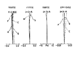
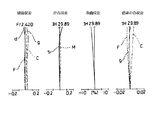
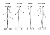
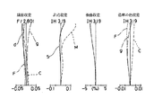
本発明の各実施例の収差状況は図12乃至図37に示す通りで、実施例1は図12、実施例2は図13、14、実施例3は図15、16、実施例4は図17、18、実施例5は図19、20、実施例6は図21、22、実施例7は図23、図24、実施例8は図25、図26、実施例9は図27、図28、実施例10は図29、図30、実施例11は図31、図32に示す通りであり、それらのうち、図12、13、15、17、19、21、23、25、27、29、31は無限遠時、図14、16、18、20、22、24、26、28、30、32は物点距離10cmの時の収差図である。また、実施例7乃至実施例11における全体繰り出しにより物体距離10cmにフォーカスした時の収差状況は図33乃至図37に示す通りである。
【0077】
以上述べた本発明の撮影光学系は、CCDやCMOSセンサー等の電子撮像素子を用いた電子カメラ等の各種撮影装置に使用することができる。
【0078】
次に本発明の撮影光学系を使用した撮影装置の例を述べる。
【0079】
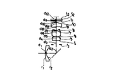
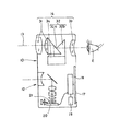
図38、図39、図40は、本発明の撮影光学系が組み込まれた電子カメラを示す図である。これら図において、図38〜図40は夫々電子カメラの外観を示す前方斜視図、電子カメラの外観を示す後方斜視図および断面図である。これら図に示すように10は電子カメラで、撮影用光路11を有する撮影光学系12とファインダー用光路13を有するファインダー光学系14とシャッター15とフラッシュ16と液晶表示モニター17とを備えている。このカメラ10の上部に配置されたシャッター15が押圧されるとそれに連動して図示していない本発明の撮影光学系である対物レンズ12を通して撮影が行なわれる。この撮影光学系12により形成される物体像は、赤外線カットフィルター21を介してCCD等の撮像素子チップ20上に形成される。
【0080】
撮像素子チップ20にて受光された物体像は、電気的に接続された処理手段18を介することにより反転されて正立正像の電子画像としてカメラ10の背面に設けられた液晶表示モニター17に表示される。また処理手段18は、撮像素子チップ20にて撮影された物体像を反転させた正立正像の電気信号に変換し、また電子情報として記録する記録手段19の制御をも行なう。この記録手段19は、処理手段18に設けられたメモリーであってもよく、図示されているような処理手段18と電気的に記録を書き込むディバイスであってもよい。
【0081】
また、ファインダー用光路13を有するファインダー用光学系14は、ファインダー用対物光学系31と、このファインダー用対物光学系にて形成された物体像を正立させるポロプリズム32と物体像を観察する観察者の眼球Eに導く接眼レンズ33とを備えている。ポロプリズム32は、前部分32aと後部分32bとに分割されており、その間に物体像が形成される面を有し、この面の上に視野枠34が配置されている。このポロプリズム32は四つの反射面を有し、ファインダー用対物光学系31にて形成された物体像を正立正像させる。
【0082】
また、カメラ10は、部品を減らしコンパクトにし、低コストにするために、ファインダー光学系14を省いてもよい。その場合は、観察者は液晶モニター17を見ながら撮影を行なうことになる。
【0083】
次に、本発明の撮影光学系を内蔵する情報処理装置の一例であるパソコンについて、図41〜図44にもとづき述べる。
【0084】
これら図のうち、図41はパソコンのカバーを開いた前方斜視図、図42はパソコン40の撮影光学系41の断面図、図44は図41における側面図である。
【0085】
これら図に示すように、パソコン40は、外部より操作者が情報を入力するためのキーボード41と、図示していない情報処理手段や記録手段と、情報を操作者に表示するモニター42と、操作射自身や周辺の像を撮影するための撮影光学系43とを有している。ここでモニター42は、図示していないバックライトにより背面より照明される透過型液晶表示素子や、前面からの光を反射して表示する反射型液晶表示素子や、CRTディスプレイ等であってもよい。また、撮影光学系は、モニター42の右上に内蔵されているが、図示する位置に限らず、モニター42の周囲やキーボードの周囲のどこでもよい。
【0086】
このパソコン40にて用いる撮影光学系は、撮影光路44上に本発明の撮影光学系43と物体像を受光する撮像素子チップ45を有しており、それらはパソコン40に内蔵されている。
【0087】
このパソコン40に内蔵されている撮影光学系のフォーカシングは、図42に示すように可動ユニット46を移動することにより前群47と反射ミラー48とを一体に上下動させ得る。つまり前群と反射ミラー48とを後群の光軸OA(R)方向に移動させ得、これによりフォーカシングが行なわれる。また、図43に示すようにCCD(撮像素子)に対して光学系を一体に上下動させてフォーカシングを行なってもよい。
【0088】
撮像チップ45にて受光された物体像は、パソコン40の処理手段(CPU)に入力され正立正像化された電子画像としてモニター42に表示される。図41にはその一例として操作者の撮影された画像45が示されている。またこの画像45は、処理手段を介して、インターネットや電話を介して、遠隔地から通信相手のパソコンに表示されるようにすることも可能である。
【0089】
次に、図45〜47は本発明の撮影光学系を内蔵した情報処理装置の一例である電話、特に持ち運びに便利な携帯電話を示すものである。
【0090】
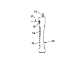
図45は携帯電話50の正面図、図46は側面図、図47は携帯電話50にて用いられる撮影光学系の断面図である。
【0091】
図45〜図47に示すように、携帯電話50は、操作者の声を情報として入力するマイク部51と、通話相手の声を出力するスピーカー部52と、操作者が情報を入力する入力ダイヤル53と、操作者自身や通話相手等の撮影像と電話番号等の情報を表示する例えば液晶表示素子のモニター54と、撮影光学系55と、通話電波の送信と受信を行なうアンテナ56と、画像情報や通信情報、入力信号等の処理を行なう処理手段(図示してない)とを有している。なお、図に示す各構成の配置位置は一例であって、これに限ることはない。
【0092】
この携帯電話50に内蔵する撮影光学系は、撮影光路57上に配置された本発明の撮影光学系からなる対物レンズ55と物体像を受光する撮像素子チップ とを有している。この撮影光学系はレンズ可動ユニットを移動することにより前群が光軸AXに沿って前後に移動することによりフォーカシングが行なわれる。
【0093】
撮影光学系55において撮像チップ58にて受光された物体像は、処理手段に入力された正立正像化された電子画像としてモニター54に表示されまたは通信相手のモニターに表示され、あるいはその両方に表示される。又処理手段には通信相手に画像を送信する場合、撮像素子チップ58にて受光された物体像の情報を、送信可能な信号に変換する信号処理機能が含まれている。
【0094】
本発明は特許請求の範囲に記載された内容のほか、下記各項に記載するものも本発明の目的を達成し得る。
【0095】
(1)特許請求の範囲の請求項1、2又は3に記載する光学系で、前記前群が、物体側より順に、物体側が凸面である負のメニスカスレンズと、物体側の面より像面側の面が曲率が大である負レンズとよりなることを特徴とする撮影光学系。
【0096】
(2)特許請求の範囲の請求項1、2又は3に記載する光学系で、前群が非球面を有する負レンズ1枚にて構成されていることを特徴とする撮影光学系。
【0097】
(3)前記の(1)の項に記載する光学系で、下記条件(4)を満足することを特徴とする撮影光学系。
(4) 0.5/|fF|<|ψ(F)|max <1.2/|fF|
【0098】
(4)前記の(2)の項に記載する光学系で、下記条件(4)を満足することを特徴とする撮影光学系。
(4) 0.5/|fF|<|ψ(F)|max <1.2/|fF|
【0099】
(5)特許請求の範囲の請求項1、2又は3あるいは前記の(1)、(2)、(3)又は(4)の項に記載する光学系で、後群の第1正レンズが下記条件(5)を満足することを特徴とする撮影光学系。
(5) 28<νP1<57
ただしνP1は後群の第1正レンズのアッベ数である。
【0100】
(6)前記(5)の項に記載する光学系で、後群の第1正レンズが下記条件(5−1)を満足する撮影光学系。
(5−1) 32<νP1<48
【0101】
(7)特許請求の範囲の請求項1、2又は3あるいは前記の(1)、(2)、(3)、(4)、(5)又は(6)の項に記載する光学系で、前群と撮像面との光軸上の間隔を変化させることによりフォーカシングを行なうようにしたことを特徴とする撮影光学系。
【0102】
(8)特許請求の範囲の請求項1、2又は3あるいは(1)、(2)、(3)、(4)、(5)又は(6)の項に記載する光学系で、前群と後群との間隔を変化させてフォーカシングを行なうことを特徴とする撮影装置。
【0103】
(9)前記の(8)の項に記載する光学系で、前群と反射部材とを後群の光軸方向に移動させることによりフォーカシングを行なうことを特徴とする撮影光学系。
【0104】
(10)前記の(8)の項に記載する光学系で、前群の光軸方向に前群を移動させることによりフォーカシングを行なうことを特徴とする撮影光学系。
【0105】
(11)特許請求の範囲の請求項1、2、3又は4あるいは前記の(1)、(2)、(3)、(4)、(5)、(6)又は(7)の項に記載する光学系において、前群を物体側に繰り出すことによりフォーカシングを行なうことを特徴とする撮影光学系。
【0106】
(12)特許請求の範囲の請求項4に記載する光学系で、前群と後群の相対的位置関係を変化させずに後群と撮像面の間隔を変化させることによりフォーカシングを行なうことを特徴とする撮影光学系。
【0107】
(13)前記の(7)の項に記載する光学系で、前群と後群の相対的位置関係を変化させずに後群と撮像面の間隔を変化させることによりフォーカシングを行なうことを特徴とする撮影光学系。
【0108】
(14)前記の(12)の項に記載する光学系で、撮像面上に配置された撮像素子を有し、撮像素子を光軸方向に移動させてフォーカシングを行なうことを特徴とする撮影光学系。
【0109】
(15)前記の(13)の項に記載する光学系で、光学系による結像面上に配置された撮像素子を有し、撮像素子を光軸方向に移動させてフォーカシングを行なうことを特徴とする撮影光学系。
【0110】
(16)特許請求の範囲の請求項1、2、3又は4に記載する光学系で、反射部材がミラーであることを特徴とする撮影光学系。
【0111】
(17)特許請求の範囲の請求項1、2、3又は4に記載する光学系で、反射部材がプリズムであることを特徴とする撮影光学系。
【0112】
(18)特許請求の範囲の請求項1、2、3又は4あるいは前記の(1)、(2)、(3)、(4)、(5)又は(6)の項に記載する光学系で、
前群と後群の屈折力を有する面が光軸に対して回転対称な球面および光軸に対して回転対称な回転対称非球面のみからなることを特徴とする撮影光学系。
【0113】
(19)前記(18)の項に記載する光学系で、反射部材が反射面を1面のみ有しかつ反射面が平面である撮影光学系。
【0114】
(20)前記の(19)の項に記載する撮影光学系を備え、光学系の撮像面に配置された撮像素子を有し、撮像素子が受光する像を表裏反転させた電気信号に変換する信号処理手段を有する撮影装置。
【0115】
(21)前記の(20)の項に記載する撮像装置で、信号処理手段により変換された電気信号をもとに撮像素子に入射した像を表裏反転させた像を表示する表示手段を有する撮影装置。
【0116】
【発明の効果】
本発明によれば、反射部材の配置が可能で、これにより光路を折り曲げてカメラボディを薄くでき、しかも収差図のように無限遠至近距離における光学性の良好な撮影光学系が得られる。
【図面の簡単な説明】
【図1】本発明の実施例1の断面図
【図2】本発明の実施例2の断面図
【図3】本発明の実施例3の断面図
【図4】本発明の実施例4の断面図
【図5】本発明の実施例5の断面図
【図6】本発明の実施例6の断面図
【図7】本発明の実施例7の断面図
【図8】本発明の実施例8の断面図
【図9】本発明の実施例9の断面図
【図10】本発明の実施例10の断面図
【図11】本発明の実施例11の断面図
【図12】本発明の実施例1の無限遠の収差曲線図
【図13】本発明の実施例2の無限遠の収差曲線図
【図14】本発明の実施例2の物体距離10cmの収差曲線図
【図15】本発明の実施例3の無限遠の収差曲線図
【図16】本発明の実施例3の物体距離10cmの収差曲線図
【図17】本発明の実施例4の無限遠の収差曲線図
【図18】本発明の実施例4の物体距離10cmの収差曲線図
【図19】本発明の実施例5の無限遠の収差曲線図
【図20】本発明の実施例5の物体距離10cmの収差曲線図
【図21】本発明の実施例6の無限遠の収差曲線図
【図22】本発明の実施例6の物体距離10cmの収差曲線図
【図23】本発明の実施例7の無限遠の収差曲線図
【図24】本発明の実施例7の前群繰り出しによる物体距離10cmの収差曲線図
【図25】本発明の実施例8の無限遠の収差曲線図
【図26】本発明の実施例8の前群繰り出しによる物体距離10cmの収差曲線図
【図27】本発明の実施例9の無限遠の収差曲線図
【図28】本発明の実施例9の前群繰り出しによる物体距離10cmの収差曲線図
【図29】本発明の実施例10の無限遠の収差曲線図
【図30】本発明の実施例10の前群繰り出しによる物体距離10cmの収差曲線図
【図31】本発明の実施例11の無限遠の収差曲線図
【図32】本発明の実施例11の前群繰り出しによる物体距離10cmの収差曲線図
【図33】本発明の実施例7の全体繰り出しによる物体距離10cmの収差曲線図
【図34】本発明の実施例8の全体繰り出しによる物体距離10cmの収差曲線図
【図35】本発明の実施例9の全体繰り出しによる物体距離10cmの収差曲線図
【図36】本発明の実施例10の全体繰り出しによる物体距離10cmの収差曲線図
【図37】本発明の実施例11の全体繰り出しによる物体距離10cmの収差曲線図
【図38】本発明の撮影光学系を用いたカメラの外観を示す前面斜視図
【図39】本発明の撮影光学系を用いたカメラの外観を示す背面斜視図
【図40】本発明の撮影光学系を用いたカメラの断面図
【図41】本発明の撮影光学系を内蔵したパソコンの外観を示す斜視図
【図42】本発明の撮影光学系を内蔵したパソコンの断面図
【図43】本発明の撮影光学系を内蔵したパソコンの他の例の断面図
【図44】本発明の撮影光学系を内蔵したパソコンの側面図
【図45】本発明の撮影光学系を内蔵した携帯電話の正面図
【図46】本発明の撮影光学系を内蔵した携帯電話の側面図
【図47】本発明の撮影光学系を内蔵した携帯電話の断面図[0001]
BACKGROUND OF THE INVENTION
The present invention relates to a retrofocus type imaging optical system suitable for cameras, particularly digital still cameras, and imaging devices provided in cellular phones, portable mobile personal computers, and the like.
[0002]
[Prior art]
As a conventional example of an optical system with a small number of lenses in a retrofocus type photographing optical system, it has been described in Japanese Patent Application Laid-Open No. 57-163212, which is an optical system having a negative, positive, negative, positive, and positive five-element configuration. An optical system described in Japanese Patent Application Laid-Open No. 64-61714, which is an optical system having five negative, positive, negative, positive, positive, or four negative, positive, negative, and positive optical systems, An optical system described in Japanese Patent Laid-Open No. 2-85816, which is an optical system having five elements, positive, negative, positive, and positive, and an optical system having five elements, negative, positive, negative, positive, and positive. An optical system described in JP-A-9-166748 is known.
[0003]
These optical systems are optical systems having a relatively small number of lenses. However, when these optical systems are used, it is difficult to sufficiently reduce the thickness of the camera body.
[0004]
An optical system is known in which the optical path is bent in order to make the camera body thinner. As conventional examples of such an optical system, there are optical systems described in JP-A-6-107070 and JP-A-9-212287. The former is for in-vehicle cameras, and has not reached the performance that can be used for digital cameras with a large number of pixels. Focusing is not considered. The latter describes optical path bending by a prism, but there is no description of data or the like, and optical performance and the like are unknown.
[0005]
[Problems to be solved by the invention]
In the present invention, it is possible to dispose a reflecting member in the optical path, and by arranging the reflecting member, the optical path can be bent vertically or horizontally to reduce the thickness of the body of the camera. A high-performance lens system with a small number of lenses and a photographic optical system suitable for an image pickup apparatus provided in a camera, particularly a digital still camera, a cellular phone, a portable mobile personal computer, and the like.
[0006]
[Means for Solving the Problems]
The photographic optical system of the present invention, in order from the object side,From two negative lenses: a negative meniscus lens with a convex surface on the object side and a negative lens with a curvature on the image side that is stronger than that on the object sideNegative power as a wholeHaveA front group, at least two positive lenses and at least one negative lens;ThanThe positive power as a wholeHaveWith the rear group,SaidWith the front groupSaidBetween the rear group,A reflecting member and an aperture stop for bending the optical path are arranged in order from the object side, and the following conditions (1) and (2) are satisfied.
[0007]
(1) 1.5 <| fF | / F <3.5
(2) 1.6 <dM /F<2.6
Where f is the focal length of the entire system, and fF Is the focal length of the front group, dM Is the air space on the optical axis from the last lens surface of the front group to the aperture stop.
[0008]
The present invention employs a retrofocus type optical system including a front group having negative power and a rear group having positive power, thereby arranging a low pass filter and an infrared cut filter necessary for a digital camera. In addition to ensuring the back focus necessary for the lens, a wide-angle optical system can be achieved.
[0009]
Further, a reflecting member such as a mirror is disposed between the front group and the rear group of the optical system so that the optical path is bent, and the thickness of the camera body is reduced.
[0010]
In addition, an aperture stop is disposed immediately behind the reflecting member so as to reduce the separation between the central beam and the peripheral beam on the reflecting member, thereby reducing the optical effective range required for the reflecting member, and the optical system. The whole is made small.
[0011]
The optical system according to the present invention satisfies the above conditions (1) and (2).
[0012]
Condition (1) regulates the focal length of the front group, thereby ensuring a desired back focus and suppressing the occurrence of distortion.
[0013]
If the lower limit of 1.5 of the condition (1) is exceeded, the focal length of the front group becomes too short, which is advantageous for securing the back focus, but the occurrence of distortion becomes large and cannot be practically used. If the upper limit of 3.5 of the condition (1) is exceeded, it will be difficult to secure the back focus, and there will be no space for placing a low-pass filter or an infrared cut filter.
[0014]
Further, the optical system of the present invention satisfies the condition (2) in order to ensure an air space for disposing the reflecting member.
[0015]
When the lower limit of 1.6 of the condition (2) is exceeded, there is no space for arranging the reflecting member, and when the upper limit of 2.6 of the condition (2) is exceeded, the total length of the optical system becomes longer. The lens diameter becomes too large and the entire optical system becomes large.
[0016]
In the optical system having the above-described configuration according to the present invention, the rear group in order from the object side is a biconvex first positive lens, a cemented lens including one positive lens and one negative lens, and a second positive lens. It is preferable that the second positive lens has an aspherical surface and satisfies the following condition (3).
(3) 2 <Sd / F <5
Sd Is the distance on the optical axis from the aperture stop to the paraxial image plane position (the filter section has an air equivalent length).
[0017]
In the rear group of the optical system of the present invention, the first positive lens has a function of converging the light beam diverged in the front group. At this time, if the curvature of the object side surface of the first lens is made gentler than the curvature of the image side surface, it is preferable because generation of spherical aberration can be suppressed.
[0018]
The cemented lens used in the rear group mainly aims to correct chromatic aberration and Petzval sum well, and the second positive lens on the image side has an action of moving the exit pupil away from the image plane. It mainly corrects astigmatism. Further, by using an aspherical surface for the second positive lens, it is possible to suppress distortion occurring in the positive lens and to achieve a wide angle.
[0019]
As described above, if the reflecting member is arranged, the camera can be downsized in the thickness direction. However, if the optical system after being bent by the reflecting member becomes large, the vertical or horizontal direction of the camera becomes large, which is not preferable. Therefore, in the optical system of the present invention, it is preferable that the condition (3) is satisfied.
[0020]
If the upper limit of 5 of the condition (3) is exceeded, the total length of the optical system becomes too long, and if the lower limit of 2 is exceeded, it is difficult to move the exit pupil position away from the image plane. When an optical system is used in an electronic imaging device such as a camera, an image is formed by shading.
[0021]
In the optical system of the present invention, it is more desirable if the following condition (3-1) is satisfied instead of condition (3).
(3-1) 2.7 <Sd /F<4.3
[0022]
In the optical system of the present invention, the front group can be constituted by a single negative meniscus lens as in Example 1 shown later, for example. However, in that case, the performance tends to deteriorate due to the eccentricity of the front group.
[0023]
When a reflecting member is disposed between the front group and the rear group, the front group tends to be eccentric with respect to the rear group in manufacturing. In order to reduce the deterioration in performance due to the eccentricity of the front group, it is desirable to make each surface of the front group a surface with a small curvature. The front group is easy to correct distortion, and in order to correct this aberration, it is preferable to use a negative meniscus lens. However, when a negative meniscus lens is used in this way, the curvature of the image side surface becomes strong.
[0024]
Therefore, in the optical system of the present invention, it is preferable to use an aspherical surface to suppress distortion aberration generated in the negative lens and to make the curvature of the surface on the image plane side of the negative lens loose.
[0025]
Further, the front group includes two negative lenses, a negative meniscus lens having a convex surface on the object side and a negative lens whose surface on the image side has a larger curvature than the surface on the object side. By sharing the entire power of the two lenses with two negative lenses, the curvature of each surface can be weakened and the occurrence of distortion can be suppressed.
[0026]
Moreover, it is desirable to satisfy the following condition (4) in order to reduce performance degradation due to eccentricity of the front group.
(4) 0.5 / | fF| <| Ψ (F) |max <1.2 / | fF|
[0027]
However, | ψ (F) |max Is the absolute value of the power of each surface in the front group, and the power ψ is given by the following equation.
ψ = (N′−N) / R
Here, N ′ and N are the refractive indices on the exit side and the incident side, respectively, and R is the radius of curvature.
[0028]
When the upper limit of the condition (4) is exceeded, a large power surface exists in the front group, so that the performance deterioration due to eccentricity becomes large. If the lower limit is exceeded, it becomes difficult to construct the front group with a small number of lenses, and the optical system becomes large, and the cost of the entire lens system increases.
[0029]
The optical system of the present invention, that is, in order from the object side, is composed of a front group consisting of at least one negative lens and having a negative power as a whole, at least two positive lenses, and at least one negative lens. An optical system that satisfies the conditions (1) and (2), comprising a rear group having power, and a reflecting member and an aperture stop for bending the optical path in order from the object side between the front group and the rear group. In the system, it is desirable that the first positive lens in the rear group (most positive lens on the object side) satisfies the following condition (5).
(5) 28 <νP1<57
Where νP1Is the Abbe number of the first positive lens.
[0030]
Abbe number νP1Exceeds the lower limit of 28 of the condition (5), the axial chromatic aberration is undercorrected, and when the upper limit of 57 is exceeded, the axial chromatic aberration is overcorrected, both of which are preferable for obtaining better optical performance. Absent.
[0031]
It is more desirable if the following condition (5-1) is satisfied instead of condition (5).
(5-1) 32 <νP1<48
[0032]
If the condition (5-1) is satisfied, a higher-performance photographing optical system can be obtained from the center to the periphery.
[0033]
Further, the photographing optical system of the present invention can perform focusing even when the front group is extended or the rear group is extended. However, the front group is a single negative lens having an aspheric surface, or a negative meniscus lens having a convex surface on the object side in order from the object side, and a negative lens having a curvature larger on the image side than on the object side. When the lens is composed of two lenses, the astigmatism and spherical aberration generated in the front group can be reduced. Therefore, if focusing is performed by extending the front group to the object side, the shooting distance will be shortened. It is possible.
[0034]
The direction in which the optical axis is bent may be the short-side direction or the long-side direction with respect to the rectangular imaging surface when an imaging element having a rectangular imaging surface is used. Bending in the short side direction is preferable because the space for the reflecting member is reduced.
[0035]
Next, preferred focusing means in the optical system of the present invention will be described.
[0036]
The imaging optical system of the present invention, that is, in order from the object side, a front group consisting of at least one negative lens and having negative power as a whole, and a rear group consisting of at least one positive lens and having positive power as a whole It is preferable to perform focusing by each of the following means in an optical system that forms an imaging surface and a photographing optical system in which a reflecting member for bending an optical path is disposed between the front group and the rear group .
[0037]
That is, focusing is performed by changing the distance on the optical axis between the front group and the imaging surface in the optical system of the present invention having the above-described configuration. For example, when focusing from an object at a long distance to an object at a short distance, the interval between the front group and the imaging surface is widened, and when focusing from an object at a short distance to an object at a long distance, the interval between the front group and the imaging surface is used. To narrow.
[0038]
In the optical system of the present invention, it is possible to focus from a long-distance object to a short-distance object by keeping the distance on the optical axis between the front group and the imaging surface constant and extending the rear group. Thus, when the front group is extended, the change in the state of the light beam passing through the rear group is less than that in the case where the rear group is extended, and the change in optical performance can be suppressed to be small. In addition, since the optical system of the present invention includes a reflecting member, it is necessary to consider decentration during manufacturing, and it is better that the interval that changes during focusing is small. When focusing is performed by extending the rear group, at least two intervals, the distance between the front group and the rear group and the distance between the rear group and the imaging surface, change, on the optical axis between the front group and the imaging surface. The method of changing the distance is preferable because only one place changes.
[0040]
If the distance between the front group and the rear group is changed in this way, the state of the light beam passing through the rear group does not change much more, and the optical performance is less affected by the eccentricity between the front group and the rear group. The production of the system becomes easy. In focusing, it is preferable to fix the positional relationship between the aperture stop and the rear group when the electronic imaging device is used because there is little change in the exit pupil position due to focusing.
[0041]
In the photographing optical system, focusing can be performed by the following means. That is, focusing is performed by moving the front group and the reflecting member in the optical axis direction of the rear group.
[0045]
Further, as the focusing in the photographing optical system, it is possible to change the interval between the rear group and the imaging surface without changing the positional relationship between the front group and the rear group.
[0046]
According to this focusing means, since the positional relationship between the front group and the rear group is fixed, the eccentric relationship between the front group and the rear group can be favorably maintained from the time of manufacture to the time of use. Further, according to this focusing means, there is one change interval, and the change in the interval due to focusing is small compared to the case where only the front group is fed out.
[0048]
Since this focusing means has a fixed positional relationship between the front group and the rear group, it can maintain the eccentric relationship between the front group and the rear group from the time of manufacture to the time of use, and further the shift of the center position of the shooting range due to the shooting distance. Will not occur. There is one interval that changes during focusing.
[0049]
DETAILED DESCRIPTION OF THE INVENTION
Next, each embodiment of the photographing optical system of the present invention will be shown.
[0060]
Examples 1 to 11 are configured as shown in FIGS.
[0061]
In Examples 1, 2, 3, 5, and 11, all of the front group including one negative lens, the aperture stop, the cemented lens including the first positive lens, the positive lens, and the negative lens, and the second positive lens are used. And a rear group.
[0062]
Of these examples, Example 1 is an image side surface (r of the first positive lens in the rear group.Five) And the image side surface of the second positive lens (rTen) Is an aspherical surface. In Example 2, the object surface of the negative lens in the front group, the image-side surface of the first positive lens in the rear group, and the image-side surface (r of the second positive lens)Ten) Is an aspheric surface, and Examples 3 and 5 are the image side surfaces of the negative lens in the front groupInA resin layer is provided and the image side surface (rThree) Is an aspheric surface and the image side surface (r of the first positive lens in the rear group)6) And the image side surface of the second positive lens (r11) Is an aspherical surface. In Example 11, the image side surface (r of the negative lens in the front group)2) And the image side surface of the second positive lens in the rear group (rTen) Is an aspherical surface.
[0063]
In Examples 4, 6, 7, 8, 9, and 10, the front group includes two negative lenses, and the rear group includes a cemented lens and a second positive lens including a first positive lens, a positive lens, and a negative lens. Become.
[0064]
Among these examples, Examples 4, 7, and 10 are the image side surfaces (r of the first positive lens in the rear group).7) And the image side surface of the second positive lens (r12) Is an aspherical surface. In Example 6, the image-side surface (r of the first positive lens in the rear group)7) And the object side surface of the second positive lens (r11) Is an aspherical surface. In Examples 8 and 9, the image-side surface (r12) Is an aspherical surface.
[0065]
In each of these Examples 1 to 11, a reflecting surface (mirror) is disposed between the front group and the aperture stop to bend the optical path.
[0066]
Of these examples, Examples 1, 2, 3, 5, and 11 are rThree Is the aperture stop.
[0067]
Examples 4, 6, 7, 8, 9, and 10 are r.Four Is the aperture stop.
[0068]
The shape of the aspherical surface used in the embodiments of the present invention is expressed by the following equation, where the optical axis direction is the x axis and the direction perpendicular to the optical axis is the y axis.
x = (y2 / R) / [1+ {1- (1 + k) (y / r)2 }1/2 + AFour yFour + A6 y6 + A8 y8 + ATenyTen
Where r is the radius of curvature of the reference sphere, k, AFour , A6 , A8 , ATenIs the aspheric coefficient.
[0069]
In the cross-sectional views (FIGS. 1 to 11) of the respective embodiments, the plane parallel plate disposed in the vicinity of the image plane represents a low-pass filter and an infrared cut filter.
[0070]
In each of the first to eleventh embodiments, a reflecting surface (mirror) is used between the front group and the aperture stop, but a prism reflecting member such as a triangular prism may be used instead of the mirror. .
[0071]
In the optical systems of Examples 2 to 11, focusing is performed by extending the front group. Only the front group may be extended in the optical axis direction of the front group, or the front group and the reflecting member may be integrated and moved in the optical axis direction of the rear group. The amount of advance of the front group when the object distance is 10 cm is as follows.
[0072]
Example 2 2.297 mm
Example 3 2.315 mm
Example 4 2.722 mm
Example 5 1.427 mm
Example 6 2.784 mm
Example 7 0.77 mm
Example 8 0.60 mm
Example 9 0.64 mm
Example 10 0.65 mm
Example 11 0.56 mm
Further, focusing may be performed by changing the distance between the rear group and the image pickup element as a unit and the relatively fixed front group.
[0073]
In Examples 7 to 11, focusing is possible even when the rear group is extended, and focusing is also possible when the entire optical system is extended.
[0074]
In the optical systems of Examples 7 to 11, the feeding amount when focusing on an object of 10 cm by the whole feeding is as follows.
[0075]
Example 7 0.19 mm
Example 8 0.19 mm
Example 9 0.19 mm
Example 10 0.21 mm
Example 11 0.19 mm
In focusing of the optical systems of these embodiments, the change in performance is small when the front group is extended, and the performance deterioration due to the eccentricity of the front group and the rear group is small when the entire group is extended. Further, focusing by the entire extension has an advantage that the amount of extension is small, and focusing on the image side (CCD side), that is, focusing can be performed by moving the image plane with respect to the optical system.
[0076]
The aberration status of each embodiment of the present invention is as shown in FIGS. 12 to 37. FIG. 12 shows the first embodiment, FIGS. 13 and 14 show the second embodiment, FIGS. 15 and 16 show the third embodiment, and FIGS. 17, 18 and Example 5 are FIGS. 19 and 20, Example 6 is FIGS. 21 and 22, Example 7 is FIGS. 23 and 24, Example 8 is FIGS. 25 and 26, Example 9 is FIG. 28, Example 10 is as shown in FIGS. 29 and 30, and Example 11 is as shown in FIGS. 31 and 32. Among them, FIGS. 12, 13, 15, 17, 19, 21, 23, 25, 27, 29 and 31 are aberration diagrams at infinity, and FIGS. 14, 16, 18, 20, 22, 24, 26, 28, 30, and 32 are aberration diagrams at an object point distance of 10 cm. In addition, the aberration state when the object distance is focused to 10 cm by the entire extension in Examples 7 to 11 is as shown in FIGS. 33 to 37.
[0077]
The photographing optical system of the present invention described above can be used in various photographing apparatuses such as an electronic camera using an electronic image pickup device such as a CCD or a CMOS sensor.
[0078]
Next, an example of a photographing apparatus using the photographing optical system of the present invention will be described.
[0079]
38, 39, and 40 are diagrams showing an electronic camera in which the photographing optical system of the present invention is incorporated. 38 to 40 are a front perspective view showing an external appearance of the electronic camera, a rear perspective view and a sectional view showing the external appearance of the electronic camera. As shown in these drawings,
[0080]
The object image received by the
[0081]
Further, the finder
[0082]
In addition, the
[0083]
Next, a personal computer which is an example of an information processing apparatus incorporating the photographing optical system of the present invention will be described with reference to FIGS.
[0084]
Among these drawings, FIG. 41 is a front perspective view with the cover of the personal computer opened, FIG. 42 is a sectional view of the photographing
[0085]
As shown in these figures, the
[0086]
The photographing optical system used in the
[0087]
In focusing of the photographing optical system built in the
[0088]
The object image received by the
[0089]
Next, FIGS. 45 to 47 show a telephone which is an example of an information processing apparatus incorporating the photographing optical system of the present invention, particularly a portable telephone which is convenient to carry.
[0090]
45 is a front view of the
[0091]
As shown in FIGS. 45 to 47, the
[0092]
The photographic optical system built in the
[0093]
The object image received by the
[0094]
In addition to the contents described in the claims, the present invention described in each of the following items can also achieve the object of the present invention.
[0095]
(1) In the optical system according to
[0096]
(2) An imaging optical system according to
[0097]
(3) An imaging optical system according to the item (1), wherein the following condition (4) is satisfied.
(4) 0.5 / | fF| <| Ψ (F) |max <1.2 / | fF|
[0098]
(4) An imaging optical system according to item (2), wherein the following condition (4) is satisfied.
(4) 0.5 / | fF| <| Ψ (F) |max <1.2 / | fF|
[0099]
(5) In the optical system described in
(5) 28 <νP1<57
Where νP1Is the Abbe number of the first positive lens in the rear group.
[0100]
(6) The photographic optical system according to (5), wherein the first positive lens in the rear group satisfies the following condition (5-1).
(5-1) 32 <νP1<48
[0101]
(7) The optical system according to
[0102]
(8) The optical system according to
[0103]
(9) A photographic optical system according to (8), wherein focusing is performed by moving the front group and the reflecting member in the optical axis direction of the rear group.
[0104]
(10) An imaging optical system according to item (8), wherein focusing is performed by moving the front group in the optical axis direction of the front group.
[0105]
(11) In
[0106]
(12) In the optical system described in
[0107]
(13) In the optical system described in (7) above, focusing is performed by changing the distance between the rear group and the imaging surface without changing the relative positional relationship between the front group and the rear group. The taking optical system.
[0108]
(14) The optical system described in the above section (12), having an image pickup device arranged on the image pickup surface, and performing focusing by moving the image pickup device in the optical axis direction system.
[0109]
(15) The optical system described in the above section (13), including an imaging device disposed on an image forming plane by the optical system, and performing focusing by moving the imaging device in the optical axis direction. The taking optical system.
[0110]
(16) An imaging optical system according to
[0111]
(17) An optical system according to
[0112]
(18) The optical system according to
An imaging optical system, wherein surfaces having refractive powers of the front group and the rear group include only a spherical surface that is rotationally symmetric with respect to the optical axis and a rotationally symmetric aspherical surface that is rotationally symmetric with respect to the optical axis.
[0113]
(19) The optical system according to item (18), wherein the reflecting member has only one reflecting surface and the reflecting surface is a flat surface.
[0114]
(20) The photographic optical system described in the above item (19) is provided, the image pickup device is disposed on the image pickup surface of the optical system, and an image received by the image pickup device is converted into an electrical signal that is reversed upside down. An imaging apparatus having signal processing means.
[0115]
(21) An image pickup apparatus according to the item (20), wherein the image pickup apparatus includes a display unit that displays an image obtained by inverting the image incident on the image sensor based on the electrical signal converted by the signal processing unit. apparatus.
[0116]
【The invention's effect】
According to the present invention, it is possible to dispose a reflecting member, whereby a camera body can be thinned by bending an optical path, and an imaging optical system having good optical properties at an infinite distance and a close distance can be obtained as shown in the aberration diagram.
[Brief description of the drawings]
FIG. 1 is a cross-sectional view of a first embodiment of the present invention.
FIG. 2 is a sectional view of
FIG. 3 is a cross-sectional view of
FIG. 4 is a sectional view of Example 4 of the present invention.
FIG. 5 is a cross-sectional view of a fifth embodiment of the present invention.
FIG. 6 is a sectional view of Example 6 of the present invention.
FIG. 7 is a sectional view of Example 7 of the present invention.
FIG. 8 is a sectional view of Example 8 of the present invention.
FIG. 9 is a sectional view of
FIG. 10 is a sectional view of Example 10 of the present invention.
FIG. 11 is a sectional view of Example 11 of the present invention.
FIG. 12 is an aberration curve diagram at infinity according to Example 1 of the present invention.
FIG. 13 is an aberration curve diagram at infinity according to Example 2 of the present invention.
FIG. 14 is an aberration curve diagram of an object distance of 10 cm according to Example 2 of the present invention.
FIG. 15 is an aberration curve diagram at infinity according to Example 3 of the present invention.
FIG. 16 is an aberration curve diagram of an object distance of 10 cm according to Example 3 of the present invention.
FIG. 17 is an aberration curve diagram at infinity according to Example 4 of the present invention.
FIG. 18 is an aberration curve diagram of an object distance of 10 cm according to Example 4 of the present invention.
FIG. 19 is an aberration curve diagram at infinity according to Example 5 of the present invention.
FIG. 20 is an aberration curve diagram of an object distance of 10 cm according to Example 5 of the present invention.
FIG. 21 is an aberration curve diagram at infinity according to Example 6 of the present invention.
FIG. 22 is an aberration curve diagram of an object distance of 10 cm according to Example 6 of the present invention.
FIG. 23 is an aberration curve diagram at infinity according to Example 7 of the present invention.
FIG. 24 is an aberration curve diagram of the object distance of 10 cm due to the front group extension according to the seventh embodiment of the present invention.
FIG. 25 is an aberration curve diagram at infinity according to Example 8 of the present invention.
FIG. 26 is an aberration curve diagram when the object distance is 10 cm due to front group extension according to the eighth embodiment of the present invention.
FIG. 27 is an aberration curve diagram at infinity according to Example 9 of the present invention.
FIG. 28 is an aberration curve diagram of the object distance of 10 cm due to the front group extension according to the ninth embodiment of the present invention.
FIG. 29 is an aberration curve diagram at infinity according to Example 10 of the present invention.
FIG. 30 is an aberration curve diagram of an object distance of 10 cm due to front group extension according to the tenth embodiment of the present invention.
FIG. 31 is an aberration curve diagram at infinity according to Example 11 of the present invention.
FIG. 32 is an aberration curve diagram of an object distance of 10 cm due to front group extension according to Example 11 of the present invention.
FIG. 33 is an aberration curve diagram of an object distance of 10 cm with the entire extension according to Example 7 of the present invention.
FIG. 34 is an aberration curve diagram when the object distance is 10 cm by the entire extension according to the eighth embodiment of the present invention.
FIG. 35 is an aberration curve diagram of the object distance of 10 cm with the entire extension according to the ninth embodiment of the present invention.
FIG. 36 is an aberration curve diagram of an object distance of 10 cm with the entire extension according to Example 10 of the present invention.
FIG. 37 is an aberration curve diagram of an object distance of 10 cm with the entire extension according to Example 11 of the present invention.
FIG. 38 is a front perspective view showing the appearance of a camera using the photographing optical system of the present invention.
FIG. 39 is a rear perspective view showing the appearance of a camera using the photographing optical system of the present invention.
FIG. 40 is a cross-sectional view of a camera using the photographing optical system of the present invention.
FIG. 41 is a perspective view showing the external appearance of a personal computer incorporating the photographing optical system of the present invention.
FIG. 42 is a cross-sectional view of a personal computer incorporating a photographing optical system according to the present invention.
FIG. 43 is a cross-sectional view of another example of a personal computer incorporating the photographing optical system of the present invention.
FIG. 44 is a side view of a personal computer incorporating the photographing optical system of the present invention.
FIG. 45 is a front view of a mobile phone incorporating a photographing optical system according to the present invention.
FIG. 46 is a side view of a mobile phone incorporating the photographing optical system of the present invention.
FIG. 47 is a cross-sectional view of a mobile phone incorporating the photographing optical system of the present invention.
Claims (2)
(1) 1.5<|fF |/f<3.5
(2) 1.6<dM /f<2.6
(3) 2<S d /f<5
ただし、fは全系の焦点距離、fF は前群の焦点距離、dM は前群のレンズ最終面から明るさ絞りまでの光軸上の空気間隔、S d は明るさ絞りから近軸像面位置までの距離である(フィルタ部は空気換算長とする)。 In order from the object side, there are two negative lenses: a negative meniscus lens with a convex surface on the object side and a negative lens with a curvature on the image side that is stronger than that on the object side. A front group having at least two positive lenses and at least one negative lens and having a positive power as a whole, and in order from the object side between the front group and the rear group. A reflecting member for bending the optical path and an aperture stop are disposed, and the rear group includes, in order from the object side, a biconvex first positive lens, a cemented lens including a positive lens and a negative lens, and a second lens An imaging optical system comprising a positive lens, wherein the second positive lens has an aspherical surface and satisfies the following conditions (1), (2) and (3) .
(1) 1.5 <| f F | / f <3.5
(2) 1.6 <d M /f<2.6
(3) 2 <S d / F <5
Where f is the focal length of the entire system, f F is the focal length of the front group, d M is the air space on the optical axis from the last lens surface of the front group to the aperture stop , and S d Is the distance from the aperture stop to the paraxial image plane position (the filter section has an air conversion length).
Priority Applications (1)
| Application Number | Priority Date | Filing Date | Title |
|---|---|---|---|
| JP36881999A JP3854769B2 (en) | 1999-02-01 | 1999-12-27 | Imaging optical system |
Applications Claiming Priority (3)
| Application Number | Priority Date | Filing Date | Title |
|---|---|---|---|
| JP11-23367 | 1999-02-01 | ||
| JP2336799 | 1999-02-01 | ||
| JP36881999A JP3854769B2 (en) | 1999-02-01 | 1999-12-27 | Imaging optical system |
Publications (3)
| Publication Number | Publication Date |
|---|---|
| JP2000292692A JP2000292692A (en) | 2000-10-20 |
| JP2000292692A5 JP2000292692A5 (en) | 2005-05-26 |
| JP3854769B2 true JP3854769B2 (en) | 2006-12-06 |
Family
ID=26360721
Family Applications (1)
| Application Number | Title | Priority Date | Filing Date |
|---|---|---|---|
| JP36881999A Expired - Fee Related JP3854769B2 (en) | 1999-02-01 | 1999-12-27 | Imaging optical system |
Country Status (1)
| Country | Link |
|---|---|
| JP (1) | JP3854769B2 (en) |
Families Citing this family (21)
| Publication number | Priority date | Publication date | Assignee | Title |
|---|---|---|---|---|
| JP4742465B2 (en) * | 2001-08-21 | 2011-08-10 | ソニー株式会社 | Imaging lens |
| JP2005244975A (en) * | 2005-02-21 | 2005-09-08 | Konica Minolta Opto Inc | Foldable portable appliance with camera |
| JP2006323212A (en) * | 2005-05-19 | 2006-11-30 | Konica Minolta Photo Imaging Inc | Lens unit and imaging apparatus having the same |
| JP2006349920A (en) * | 2005-06-15 | 2006-12-28 | Ricoh Co Ltd | Photographing optical system, photographic lens unit, camera and personal digital assistant |
| JP2007034103A (en) | 2005-07-29 | 2007-02-08 | Eastman Kodak Co | Wide angle lens and camera |
| EP1967882B1 (en) | 2007-03-09 | 2011-06-29 | Nikon Corporation | Zoom lens of the telephoto type and having four lens groups |
| JP5071773B2 (en) * | 2007-03-09 | 2012-11-14 | 株式会社ニコン | Zoom lens, optical apparatus, and imaging method |
| JP5245320B2 (en) | 2007-08-13 | 2013-07-24 | 株式会社ニコン | Zoom lens, optical instrument using the same, and imaging method |
| JP2010145828A (en) * | 2008-12-19 | 2010-07-01 | Tamron Co Ltd | Imaging lens |
| JP5468966B2 (en) * | 2010-04-02 | 2014-04-09 | 富士フイルム株式会社 | Projection lens and projection display device using the same |
| JP5096517B2 (en) * | 2010-04-28 | 2012-12-12 | オリンパス株式会社 | Imaging optical system or imaging device |
| JP2013073157A (en) * | 2011-09-29 | 2013-04-22 | Fujifilm Corp | Image pickup lens and image pickup apparatus |
| JP5629251B2 (en) * | 2011-09-29 | 2014-11-19 | 富士フイルム株式会社 | Imaging lens and imaging apparatus |
| CN105793755B (en) | 2013-10-30 | 2019-04-30 | 奥林巴斯株式会社 | Photographic device |
| WO2017086050A1 (en) | 2015-11-20 | 2017-05-26 | ソニー株式会社 | Imaging lens |
| JP6741019B2 (en) * | 2015-11-20 | 2020-08-19 | ソニー株式会社 | Imaging lens and in-vehicle imaging device |
| CN108663772B (en) * | 2017-03-31 | 2022-07-05 | 宁波舜宇车载光学技术有限公司 | Optical lens and imaging apparatus |
| CN107797259A (en) * | 2017-11-30 | 2018-03-13 | 福建福光股份有限公司 | A kind of super clear 4K tight shots of 5.2mm |
| CN110398872A (en) * | 2018-04-25 | 2019-11-01 | 华为技术有限公司 | A kind of lens module and camera |
| TWI676061B (en) * | 2018-08-10 | 2019-11-01 | 大立光電股份有限公司 | Imaging optical lens assembly, image capturing unit and electronic device |
| JP7285091B2 (en) * | 2019-02-27 | 2023-06-01 | 株式会社タムロン | Imaging optical system and imaging device |
-
1999
- 1999-12-27 JP JP36881999A patent/JP3854769B2/en not_active Expired - Fee Related
Also Published As
| Publication number | Publication date |
|---|---|
| JP2000292692A (en) | 2000-10-20 |
Similar Documents
| Publication | Publication Date | Title |
|---|---|---|
| JP3854769B2 (en) | Imaging optical system | |
| US9019394B2 (en) | Image forming optical system, image pickup apparatus using the same, and information processing apparatus | |
| US6339508B1 (en) | Photographic optical system | |
| JP5427077B2 (en) | Imaging optical system and imaging apparatus using the same | |
| JP3909989B2 (en) | Camera with zoom lens and electronic image sensor | |
| US20120081595A1 (en) | Image taking optical system and image pickup apparatus equipped with same | |
| JP2004205796A (en) | Optical path bending zoom optical system | |
| JP2005266129A (en) | Zoom lens and electronic imaging apparatus having the same | |
| JP4477336B2 (en) | Zoom lens and electronic imaging apparatus using the same | |
| JP4813102B2 (en) | Zoom lens and electronic imaging apparatus using the same | |
| JP5226166B2 (en) | Bending imaging optical system | |
| JP2012208148A (en) | Image pickup optical system and image pickup device using the same | |
| JP4584483B2 (en) | Imaging optical system | |
| JP4869522B2 (en) | Optical path bending zoom optical system | |
| JP4790320B2 (en) | Two-group zoom lens and electronic imaging apparatus including the same | |
| JP4079630B2 (en) | Imaging lens and imaging apparatus including the same | |
| JP4573378B2 (en) | Zoom lens | |
| JP5226888B2 (en) | Bending imaging optical system | |
| JP2013195781A (en) | Imaging optical system, and imaging device using the same | |
| US8704936B2 (en) | Image forming optical system, image pickup apparatus using the same, and information processing apparatus | |
| JP5663367B2 (en) | Imaging optical system and imaging apparatus using the same | |
| JP5717988B2 (en) | Variable magnification optical system and imaging apparatus using the same | |
| JP4472070B2 (en) | Zoom lens | |
| JP4503957B2 (en) | Three-group zoom lens and electronic imaging apparatus using the same | |
| JP4632706B2 (en) | Imaging device |
Legal Events
| Date | Code | Title | Description |
|---|---|---|---|
| A521 | Request for written amendment filed |
Free format text: JAPANESE INTERMEDIATE CODE: A523 Effective date: 20040805 |
|
| A621 | Written request for application examination |
Free format text: JAPANESE INTERMEDIATE CODE: A621 Effective date: 20040805 |
|
| A977 | Report on retrieval |
Free format text: JAPANESE INTERMEDIATE CODE: A971007 Effective date: 20060203 |
|
| A131 | Notification of reasons for refusal |
Free format text: JAPANESE INTERMEDIATE CODE: A131 Effective date: 20060314 |
|
| A521 | Request for written amendment filed |
Free format text: JAPANESE INTERMEDIATE CODE: A523 Effective date: 20060428 |
|
| A131 | Notification of reasons for refusal |
Free format text: JAPANESE INTERMEDIATE CODE: A131 Effective date: 20060613 |
|
| A521 | Request for written amendment filed |
Free format text: JAPANESE INTERMEDIATE CODE: A523 Effective date: 20060719 |
|
| TRDD | Decision of grant or rejection written | ||
| A01 | Written decision to grant a patent or to grant a registration (utility model) |
Free format text: JAPANESE INTERMEDIATE CODE: A01 Effective date: 20060905 |
|
| A61 | First payment of annual fees (during grant procedure) |
Free format text: JAPANESE INTERMEDIATE CODE: A61 Effective date: 20060911 |
|
| FPAY | Renewal fee payment (event date is renewal date of database) |
Free format text: PAYMENT UNTIL: 20090915 Year of fee payment: 3 |
|
| FPAY | Renewal fee payment (event date is renewal date of database) |
Free format text: PAYMENT UNTIL: 20100915 Year of fee payment: 4 |
|
| FPAY | Renewal fee payment (event date is renewal date of database) |
Free format text: PAYMENT UNTIL: 20110915 Year of fee payment: 5 |
|
| FPAY | Renewal fee payment (event date is renewal date of database) |
Free format text: PAYMENT UNTIL: 20120915 Year of fee payment: 6 |
|
| FPAY | Renewal fee payment (event date is renewal date of database) |
Free format text: PAYMENT UNTIL: 20130915 Year of fee payment: 7 |
|
| S531 | Written request for registration of change of domicile |
Free format text: JAPANESE INTERMEDIATE CODE: R313531 |
|
| R350 | Written notification of registration of transfer |
Free format text: JAPANESE INTERMEDIATE CODE: R350 |
|
| LAPS | Cancellation because of no payment of annual fees |