JP3854018B2 - Automatic control method - Google Patents
Automatic control method Download PDFInfo
- Publication number
- JP3854018B2 JP3854018B2 JP26371099A JP26371099A JP3854018B2 JP 3854018 B2 JP3854018 B2 JP 3854018B2 JP 26371099 A JP26371099 A JP 26371099A JP 26371099 A JP26371099 A JP 26371099A JP 3854018 B2 JP3854018 B2 JP 3854018B2
- Authority
- JP
- Japan
- Prior art keywords
- temperature
- value
- time
- time constant
- primary filter
- Prior art date
- Legal status (The legal status is an assumption and is not a legal conclusion. Google has not performed a legal analysis and makes no representation as to the accuracy of the status listed.)
- Expired - Fee Related
Links
Images


Description
【0001】
【発明の属する技術分野】
本発明は、制御対象の制御量を、時間的に変化する目標値に追従させる自動制御方法に係り、特に、目標値の変化パターンに対する追従性に優れた設定値の設定方法に関する。
【0002】
【従来の技術】
図6に、サーボ系の制御システムにおいて、制御量(プロセス変数)の目標値の変化に応じて設定値を設定する方法の各種の例を示す。
【0003】
図6(a)は、ステップ状のパターンを用いて設定値を設定した例である。この様なパターンを使用した場合、制御量に大きなオーバーシュートが発生したり、設定値の急激な変化に対して制御量が十分に追従できなくなるという問題がある。
【0004】
図6(b)は、線形のパターンを用いて設定値を設定した例である。この様なパターンを使用した場合、設定値が瞬時に変化することがないので、設定値の時間変化に制御量を正確に追従させることができる。
【0005】
図6(c)は、一次フィルタを用いて設定値を設定する例である。この様なパターンを使用した場合、全体的には応答が速く、同時に、オーバーシュートが発生しにくい。しかし、最終設定値付近での収束は遅くなる。
【0006】
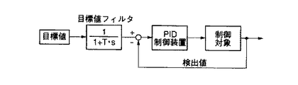
図7に、いわゆる目標値フィルタを組み入れたサーボ制御系のブロック線図の一例を示す。ここで、Tは時定数、sはラプラス演算子を表わす。この例では、PID制御が使用され、「目標値フィルタ付きPID制御」とも呼ばれている。この様な制御方法は、高速で且つオーバーシュートも少なく、制御量を目標値に正確に追従させることができる。
【0007】
(従来技術の問題点)
例えば、シリコンウエーハの様な平板状の被加熱物を昇温する際、被加熱物の全面をむらなく均一な温度分布状態で維持したまま、所定の温度まで到達させることが要求される場合がある。その様な場合、ヒータを同心円状の複数のゾーンに分割し、各ゾーンをそれぞれ独立に制御することによって被加熱物の温度分布の均一化を図るとともに、昇温過程においても、ヒータの各ゾーンに対応する被加熱物の各位置の温度を、正確に設定値に対して追従させる必要がある。
【0008】
この様な複数のゾーンから構成されるヒータを用いた加熱装置の制御に、先に図6(a)から(c)に示した設定値の設定用のパターンを適用した場合、以下の様な問題点がある。
【0009】
図6(a)に示したステップ状のパターンを用いた場合、昇温過程は、個別の加熱ゾーンの制御特性のみに依存し、温度むらの問題は全く考慮されないことになる。
【0010】
図6(b)に示した線形のパターンを用いた場合、昇温過程を考慮することができる。しかし、制御対象の熱的特性によっては、制御量を正確に設定値に追従させるために直線の傾きを緩やかに設定しなければならず、応答が遅くなってしまう。また、パターン中の直線と直線とのつなぎ目において、制御量に振動やオーバーシュートが生じ易く、温度むらが発生する要因となる。
【0011】
図6(c)に示した一次フィルタ状のパターンを用いた場合、設定値の変化に対して制御量を高速で応答させることができるとともに、オーバーシュートが生じ難く、最終設定値付近での温度むらが小さくなる。しかし、目標値の変更直後に大きな操作量(制御入力)が必要とされる。特に、各ゾーンの制御特性に偏りがある場合には、特定のゾーンに長時間100%以上の出力が要求される。その様な場合、被加熱物に加熱むらが発生することになる。また、先に述べた様に、全体的には応答が速いが、最終設定値付近での収束は遅くなる。
【0012】
図8に、通常の二次フィルタのパターンを示す。立ち上がりの部分の傾斜は、先に図6(c)で示した一次フィルタと比較して、多少は緩やかになるが、全体としては大差がない。なお、フィルタの時定数を大きくすれば、立ち上がり部分の傾斜を更に緩やかにすることができるが、それに伴い、全体的に応答が遅くなってしまう。従って、二次フィルタを用いて、立ち上がり部分だけを改善することはできない。
【0013】
ウエーハの加熱装置において、ウエーハの温度(制御量)を非接触状態で検出するためのセンサとして、放射温度計が用いられている。放射温度計は、測定対象物から放射される赤外線のエネルギーを検出して温度に変換しているが、温度の低下に伴いエネルギー量が急速に減少するので、広い温度範囲で正確に被加熱物の温度を測定することはできない。そのため、例えば高温領域用の放射温度計では、500〜1300℃といった様な測定範囲が規定されている。
【0014】
測定下限値が500℃の放射温度計を用いてフィードバック制御を行う場合には、設定温度の下限値を、放射温度計の測定下限値(500℃)よりもある程度高い温度(例えば550℃程度)に設定する必要がある。
【0015】
図9に、ヒータ及び放射温度計(測定範囲:500〜1300℃)を備えた加熱装置を用いて、ウエーハを室温から1000℃まで昇温したときの温度測定結果の一例を示す。図中、破線4はウエーハの温度の設定値、実線5は放射温度計による検出値である。
【0016】
なお、この例では、ウエーハを面内で均一に加熱するため、ヒータを同心円上に複数のゾーンに分割し、それぞれのゾーン毎に独立にフィードバック制御を行っている。また、フィードバック制御は、550℃以上の温度範囲で行っている。ウエーハの温度が1000℃に到達した後、ウエーハの温度を1000℃に維持し、この状態で、ウエーハ上にシリコン薄膜の堆積を行っている。図9に示したデータは、ウエーハの表面で、上記の複数のゾーンの内の一つに対応する位置におけるデータである。
【0017】
ウエーハには、面内の温度差が大きくなると、スリップと呼ばれる結晶転移が生じる。この様なスリップは、当該ウエーハを用いて生産される半導体素子の不良の原因となる。スリップは、高温になる程発生し易いが、600℃程度でも発生すると言われている。このため、ウエーハを1000℃まで昇温する過程において、600℃以上の状態では、ウエーハの面内の温度差を、できる限り小さくしなければならない。
【0018】
ところで、ウエーハの温度について、フィードバック制御可能な温度が550℃程度以上なので、この温度を最初の設定温度とする。ウエーハの温度が550℃に到達するのを待ち、550℃に到達した後、550℃から1000℃まで温度設定値を線形に変化させる。この場合、500℃以下ではウエーハの温度が測定できないので、温度が低い状態が続くと、ヒータ出力が100%に達してしまう。そのため、温度が測定可能な500℃以上になっても、フィードバックによるブレーキ効果がすぐには現れず、550℃に到達した直後におけるオーバーシュートが大きくなり、面内の温度差も大きくなる。なお、設定値を曲線状に変化させれば、オーバーシュートや面内の温度差の減少が期待できる。しかし、ウエーハの種類によって温度が室温から600℃程度まで上昇する時間が異なり、適切な設定値曲線を決めることは容易ではない。
【0019】
【発明が解決しようとする課題】
本発明は、以上の様な放射温度計を用いた従来の温度制御方法の問題点に鑑みなされたもので、本発明の目的は、制御対象の制御量を、時間的に変化する目標値に対して追従させる自動制御の際、制御量を目標値に対して正確に追従させることができる設定値の設定方法を提供することにある。
【0020】
【課題を解決するための手段】
本発明の自動制御方法は、
使用される放射温度計の測定可能範囲の下限値よりも低い温度から制御対象の加熱を開始し、制御対象の温度が、前記下限値の近傍で前記下限値よりも高く設定された所定の温度に到達した後、制御対象の温度を前記放射温度計で測定し、その出力を主フィードバック信号として用いて、制御対象の温度を、時間的に変化する目標値に対して追従させる自動制御方法であって、
前記目標値を、複数の一次フィルタを順に介してフィードバック制御系に入力することによって、操作量を決定する様に構成するとともに、
前記複数の一次フィルタの内の少なくとも一つの一次フィルタの時定数を、時間毎に変更できる様に構成し、
前記少なくとも一つの一次フィルタの時定数の初期値と最終値を設定し、
制御対象の温度が前記所定の温度に到達した後、前記少なくとも一つの一次フィルタの時定数を、時間経過に従って前記初期値から前記最終値まで次第に増大または減少するように、時間毎に変更すること、を特徴とする
【0021】
本発明の自動制御方法によれば、制御対象の温度が前記所定の温度に到達した後、前記少なくとも一つの一次フィルタの時定数を、時間経過に従って前記初期値から前記最終値まで次第に増大または減少するように、時間毎に変更することによって、前記目標値が連続した曲線状に変換される。その結果、目標値に対する制御量の追従性を向上させることができる。
【0022】
なお、前記少なくとも一つの一次フィルタの時定数を、制御量の検出値に対応させて変更する方法もある。
【0023】
【発明の実施の形態】
以下、本発明に基づく自動制御方法の一例について説明する。
【0024】
図1に、本発明に基づく自動制御方法のブロック線図を示す。PID制御装置1の前段に、二つの一次フィルタ2及び3が直列に接続されている。制御量の目標値は、一次フィルタ2及び一次フィルタ3を順に経て、フィードバック制御系を構成するPID制御装置1に送られる。図中、sはラプラス演算子を表わす。なお、この例では、前段側の一次フィルタ3の時定数T1は、固定値であるが、後段側の一次フィルタ2の時定数T2は、時間毎に可変に設定することができる。これらの機能は、マイクロコンピュータで実現される。
【0025】
次に、後段側の一次フィルタ2における演算の具体的な内容について説明する。一次フィルタ2が図2に示す様なブロック線図で表わされる場合、マイクロコンピュータでは、次式に従って入力信号X(n)から出力信号Y(n)が計算される。
【0026】
Y(n)=Y(n−1)+(ΔT/T2)・X(n) ・・・(1)
ここで、“n”は現在のサンプリングナンバー、“n−1”は一つ前のサンプリングナンバー、ΔTはサンプリング時間を示す。T2は、一次フィルタ2の時定数で、この例では、その値が時間毎に変化させることができる。
【0027】
図3に、時定数を時間毎に変化させる際、刻々の時定数を算出するフローチャートの一例を示す。このフローチャートは、目標値の変更直後の立ち上がりを、ゆっくりと応答させる際の例である。時定数T2の初期値をT2s、最終値をT2eとし、T2s>T2eとする。離散値計算のサンプリングタイミング毎に一定の値mをT2から減算して行き、T2の値がT2eより小さくなったら、そこで減算を終了させる。なお、この計算は、設定値変更時間より短い時間で終了してもかまわない。
【0028】
図4に、この様にして作成された設定値の時間変化のパターンを示す。先に図8で示した通常の二次フィルタと比べて、立ち上がり時にも緩やかに応答させることによって制御出力を抑え、温度むらを減少させることができる。この様な曲線形状は、どこの位置でも連続的なので応答が振動的になりにくく、温度むらも生じにくくなる。また、応答速度も遅くならない。
【0029】
図4に示した例で、時定数の初期値T2sの値を、より大きく設定すれば立ち上がりが緩やかになって行く。また、サンプリングタイミング毎に時定数の値から一定の値を減算して行ったが、この一定の値を大きく取れば急速に応答が速くなる。
【0030】
なお、上記の例では、サンプリングタイミング毎に時定数の減算を行っているが、数サンプリング毎に時定数の減算を行っても良い。また、減算ではなく、一定の値を加算して行くこともできる。その場合には、初めは急で、徐々にゆっくりとした応答になって行く。また、上記の例では、設定値を増大させているか、減少させる場合でもかまわない。
【0031】
図5に、先に図9に示した例の場合と同様に、ヒータ及び放射温度計(測定範囲:500〜1300℃)を備えた加熱装置を用いて、ウエーハを室温から1000℃まで昇温したときの温度測定結果を示す。図中、破線4はウエーハの温度の設定値、実線5は放射温度計による検出値である。ウエーハの温度は、図1に示したフローに従って制御される。
【0032】
温度の目標値の初期値を510℃、最終値を1000℃とする。後段側の一次フィルタ2の時定数T2の初期値を大きく取り、時間毎に徐々に減少させて行く。また、この減少の速度もゆっくりしたものにしておく。設定値は、制御開始時は、ゆっくりと上昇していく、温度計による測定値が520℃を超えたら、時定数の減少速度を速くして行き、最終設定値の1000℃まで連続的に時定数を変化させる。設定値の時間変化を表す曲線がどこでも連続であるので、温度分布が発生しにくく、制御対象(被加熱物)の特性が異なっても、事前に設定値曲線を決めることなく、自動的に制御対象に合った設定値曲線で温度制御をすることができる。また、応答を速くすることもできる。
【0033】
制御対象の温度を複数のヒータゾーンで制御する場合は、ゾーンの中でどれか1つのゾーンにおいて設定値曲線を作成し、全てのゾーンについての共通の設定値として用いれば温度分布を少なくすることができる。なお、この場合には、一番応答が速いゾーンを共通の設定値とすればよい。
【0034】
【発明の効果】
本発明の自動制御方法によれば、時間対設定値の曲線の形状を、容易に且つ大きな自由度で定めることができる。更に、制御対象の状態(制御量)を検出するセンサからの出力に連動させて時定数を変化させることによって、制御対象の系の特性に合わせて時定数を選択することができ、この結果、追従性を更に高めることができる。
【0035】
以上の結果、本発明の自動制御方法によれば、制御対象の系の特性に合わせ、正確に設定値に追従させてサーボ制御を行うことができる。
【図面の簡単な説明】
【図1】本発明に基づく自動制御方法の一例を表すブロック線図。
【図2】図1中の一次フィルタ2による演算の内容を説明する図。
【図3】図1中の一次フィルタ2の時定数T2の設定方法の一例を示すフローチャート。
【図4】本発明の自動制御方法において生成される設定値曲線の一例。
【図5】本発明の自動制御方法に基づいてシリコンウエーハの加熱を行った時の、シリコンウエーハの温度変化の一例。
【図6】設定値を作成する際の方法の各種の例を示す図、(a)はステップ状のパターン、(b)は線形のパターン、(c)は一次フィルタを用いたパターンを表す。
【図7】従来のいわゆる目標値フィルタ付きPID制御のブロック線図。
【図8】従来の二次フィルタを用いて作成された設定値曲線の例。
【図9】ウエーハを加熱する際、従来の線形のパターンを用いて設定値を作成した時の温度制御結果のデータの一例を示す図。
【符号の説明】
1・・・PID制御装置、
2・・・時定数が可変の一次フィルタ、
3・・・時定数が固定の一次フィルタ、
4・・・温度設定値を示す点線、
5・・・温度測定値を示す実線。[0001]
BACKGROUND OF THE INVENTION
The present invention relates to an automatic control method for causing a control amount of a controlled object to follow a target value that changes with time, and more particularly, to a setting method for setting a set value that is excellent in followability to a change pattern of a target value.
[0002]
[Prior art]
FIG. 6 shows various examples of a method for setting a set value in accordance with a change in a target value of a controlled variable (process variable) in a servo control system.
[0003]
FIG. 6A shows an example in which the set value is set using a stepped pattern. When such a pattern is used, there is a problem that a large overshoot occurs in the control amount or that the control amount cannot sufficiently follow a sudden change in the set value.
[0004]
FIG. 6B shows an example in which the set value is set using a linear pattern. When such a pattern is used, the set value does not change instantaneously, so that the control amount can accurately follow the time change of the set value.
[0005]
FIG. 6C shows an example in which the set value is set using a primary filter. When such a pattern is used, the overall response is fast, and at the same time, overshoot is unlikely to occur. However, convergence near the final set value is slow.
[0006]
FIG. 7 shows an example of a block diagram of a servo control system incorporating a so-called target value filter. Here, T represents a time constant, and s represents a Laplace operator. In this example, PID control is used, which is also called “PID control with a target value filter”. Such a control method is high-speed and has little overshoot, and the control amount can accurately follow the target value.
[0007]
(Problems of conventional technology)
For example, when heating a flat object to be heated such as a silicon wafer, it may be required to reach a predetermined temperature while maintaining the entire surface of the object to be heated in a uniform temperature distribution state. is there. In such a case, the heater is divided into a plurality of concentric zones, and each zone is controlled independently to achieve a uniform temperature distribution of the object to be heated. It is necessary to accurately follow the temperature at each position of the heated object corresponding to the set value.
[0008]
When the set value setting patterns shown in FIGS. 6A to 6C are applied to the control of the heating apparatus using the heaters configured by such a plurality of zones, the following is performed. There is a problem.
[0009]
When the step-like pattern shown in FIG. 6A is used, the temperature rising process depends only on the control characteristics of the individual heating zones, and the problem of temperature unevenness is not considered at all.
[0010]
When the linear pattern shown in FIG. 6B is used, the temperature rising process can be considered. However, depending on the thermal characteristics of the controlled object, the slope of the straight line must be set gently in order to cause the control amount to accurately follow the set value, resulting in a slow response. In addition, vibrations and overshoots are likely to occur in the controlled variable at the joint between the straight lines in the pattern, which causes temperature unevenness.
[0011]
When the primary filter pattern shown in FIG. 6C is used, the control amount can be made to respond at high speed to the change in the set value, and overshoot hardly occurs. Unevenness is reduced. However, a large manipulated variable (control input) is required immediately after the target value is changed. In particular, when there is a bias in the control characteristics of each zone, an output of 100% or more is required for a specific zone for a long time. In such a case, heating unevenness occurs in the object to be heated. Moreover, as described above, the overall response is fast, but the convergence near the final set value is slow.
[0012]
FIG. 8 shows a typical secondary filter pattern. The slope of the rising portion is somewhat gentler than that of the primary filter previously shown in FIG. 6C, but there is no significant difference as a whole. Note that if the time constant of the filter is increased, the slope of the rising portion can be made gentler, but the overall response is slowed accordingly. Therefore, it is not possible to improve only the rising portion using the secondary filter.
[0013]
In a wafer heating apparatus, a radiation thermometer is used as a sensor for detecting a wafer temperature (control amount) in a non-contact state. The radiation thermometer detects infrared energy emitted from the object to be measured and converts it into temperature. However, as the temperature decreases, the amount of energy decreases rapidly, so the object to be heated accurately over a wide temperature range. Temperature cannot be measured. Therefore, for example, in a radiation thermometer for a high temperature region, a measurement range such as 500 to 1300 ° C. is defined.
[0014]
When feedback control is performed using a radiation thermometer having a measurement lower limit value of 500 ° C., the lower limit value of the set temperature is somewhat higher than the measurement lower limit value (500 ° C.) of the radiation thermometer (eg, about 550 ° C.). Must be set to
[0015]
FIG. 9 shows an example of a temperature measurement result when the wafer is heated from room temperature to 1000 ° C. using a heating device equipped with a heater and a radiation thermometer (measurement range: 500 to 1300 ° C.). In the figure, the broken line 4 is the set value of the wafer temperature, and the
[0016]
In this example, in order to uniformly heat the wafer in the plane, the heater is divided into a plurality of zones on a concentric circle, and feedback control is performed independently for each zone. The feedback control is performed in a temperature range of 550 ° C. or higher. After the wafer temperature reaches 1000 ° C., the wafer temperature is maintained at 1000 ° C., and in this state, a silicon thin film is deposited on the wafer. The data shown in FIG. 9 is data at a position corresponding to one of the plurality of zones on the wafer surface.
[0017]
In the wafer, when the in-plane temperature difference becomes large, crystal transition called slip occurs. Such a slip causes a defect of a semiconductor element produced using the wafer. Slip is more likely to occur at higher temperatures, but is said to occur even at about 600 ° C. For this reason, in the process of raising the temperature to 1000 ° C., the temperature difference in the plane of the wafer must be made as small as possible when the temperature is 600 ° C. or higher.
[0018]
By the way, about the temperature of a wafer, since the temperature which can be feedback-controlled is about 550 degreeC or more, this temperature is made into the first setting temperature. Waiting for the wafer temperature to reach 550 ° C., and after reaching 550 ° C., the temperature setting value is linearly changed from 550 ° C. to 1000 ° C. In this case, since the wafer temperature cannot be measured at 500 ° C. or lower, the heater output reaches 100% if the temperature remains low. For this reason, even when the temperature reaches 500 ° C. or higher, the braking effect due to feedback does not appear immediately, the overshoot immediately after reaching 550 ° C. increases, and the in-plane temperature difference also increases. Note that if the set value is changed in a curved line, overshoot and a decrease in the in-plane temperature difference can be expected. However, the time for the temperature to rise from room temperature to about 600 ° C. differs depending on the type of wafer, and it is not easy to determine an appropriate set point curve.
[0019]
[Problems to be solved by the invention]
The present invention has been made in view of the problems of the conventional temperature control method using the radiation thermometer as described above, and an object of the present invention is to set the controlled variable to be controlled to a target value that changes with time. An object of the present invention is to provide a setting method for setting a set value that can cause the control amount to accurately follow the target value in the automatic control to be followed.
[0020]
[Means for Solving the Problems]
The automatic control method of the present invention
The heating of the control object is started from a temperature lower than the lower limit value of the measurable range of the radiation thermometer used, and the temperature of the control object is set to be higher than the lower limit value in the vicinity of the lower limit value In this automatic control method, the temperature of the controlled object is measured with the radiation thermometer, and the output is used as a main feedback signal so that the temperature of the controlled object follows the target value that changes over time. There,
The target value is configured to determine the operation amount by inputting the target value to the feedback control system through a plurality of primary filters in order,
A time constant of at least one primary filter of the plurality of primary filters is configured to be changeable every time,
Set the initial and final values of the time constant of the at least one primary filter,
After the temperature of the controlled object has reached the predetermined temperature, the time constant of the at least one primary filter, so as to gradually increase or decrease from the initial value to the final value with the lapse of time, changing every time , [0021] characterized by
According to the automatic control method of the present invention, after the temperature to be controlled reaches the predetermined temperature, the time constant of the at least one primary filter is gradually increased or decreased from the initial value to the final value over time. As described above, the target value is converted into a continuous curve by changing every time. As a result, the followability of the control amount with respect to the target value can be improved.
[0022]
There is also a method of changing the time constant of the at least one primary filter in accordance with the detected value of the control amount.
[0023]
DETAILED DESCRIPTION OF THE INVENTION
Hereinafter, an example of the automatic control method based on this invention is demonstrated.
[0024]
FIG. 1 shows a block diagram of an automatic control method according to the present invention. Two
[0025]
Next, specific contents of the calculation in the
[0026]
Y (n) = Y (n−1) + (ΔT / T2) · X (n) (1)
Here, “n” indicates the current sampling number, “n−1” indicates the previous sampling number, and ΔT indicates the sampling time. T2 is a time constant of the
[0027]
FIG. 3 shows an example of a flowchart for calculating the time constant every time when the time constant is changed every time. This flowchart is an example in which the rise immediately after the change of the target value is made to respond slowly. The initial value of the time constant T2 is T2s, the final value is T2e, and T2s> T2e. A constant value m is subtracted from T2 at every sampling timing of the discrete value calculation, and when the value of T2 becomes smaller than T2e, the subtraction is terminated there. Note that this calculation may be completed in a time shorter than the set value change time.
[0028]
FIG. 4 shows a time change pattern of the set value created in this way. Compared with the normal secondary filter shown in FIG. 8 earlier, the control output can be suppressed and the temperature unevenness can be reduced by causing a gentle response even at the time of rising. Since such a curved shape is continuous everywhere, the response is less likely to vibrate and temperature variations are less likely to occur. Also, the response speed does not slow down.
[0029]
In the example shown in FIG. 4, when the initial value T2s of the time constant is set larger, the rise becomes gentle. In addition, a constant value is subtracted from the value of the time constant at each sampling timing, but if this constant value is increased, the response is rapidly increased.
[0030]
In the above example, the time constant is subtracted every sampling timing, but the time constant may be subtracted every several samplings. In addition, a fixed value can be added instead of subtraction. In that case, the response is steep at first, and gradually becomes slower. In the above example, the set value may be increased or decreased.
[0031]
As in the case of the example shown in FIG. 9, the temperature of the wafer is raised from room temperature to 1000 ° C. using a heating device equipped with a heater and a radiation thermometer (measurement range: 500 to 1300 ° C.). The temperature measurement results are shown. In the figure, the broken line 4 is the set value of the wafer temperature, and the
[0032]
The initial temperature target value is 510 ° C., and the final value is 1000 ° C. The initial value of the time constant T2 of the
[0033]
When controlling the temperature to be controlled with multiple heater zones, create a set value curve in any one of the zones and use it as a common set value for all zones to reduce the temperature distribution. Can do. In this case, the zone with the fastest response may be set as a common set value.
[0034]
【The invention's effect】
According to the automatic control method of the present invention, the shape of the curve of time versus set value can be easily determined with a large degree of freedom. Furthermore, by changing the time constant in conjunction with the output from the sensor that detects the state (control amount) of the controlled object, the time constant can be selected according to the characteristics of the system to be controlled. Followability can be further improved.
[0035]
As a result, according to the automatic control method of the present invention, servo control can be performed by accurately following the set value in accordance with the characteristics of the system to be controlled.
[Brief description of the drawings]
FIG. 1 is a block diagram showing an example of an automatic control method according to the present invention.
FIG. 2 is a diagram for explaining the contents of calculation by the
FIG. 3 is a flowchart showing an example of a method for setting a time constant T2 of the
FIG. 4 is an example of a set value curve generated in the automatic control method of the present invention.
FIG. 5 shows an example of a temperature change of a silicon wafer when the silicon wafer is heated based on the automatic control method of the present invention.
6A and 6B are diagrams illustrating various examples of a method for creating a set value. FIG. 6A illustrates a stepped pattern, FIG. 6B illustrates a linear pattern, and FIG. 6C illustrates a pattern using a primary filter.
FIG. 7 is a block diagram of conventional PID control with a so-called target value filter.
FIG. 8 is an example of a set value curve created using a conventional secondary filter.
FIG. 9 is a diagram showing an example of temperature control result data when a set value is created using a conventional linear pattern when a wafer is heated.
[Explanation of symbols]
1 ... PID control device,
2 ... Primary filter with variable time constant,
3 ... Primary filter with a fixed time constant,
4 ... Dotted line indicating temperature setting value,
5: Solid line showing the temperature measurement value.
Claims (1)
前記目標値を、複数の一次フィルタを順に介してフィードバック制御系に入力することによって、操作量を決定する様に構成するとともに、
前記複数の一次フィルタの内の少なくとも一つの一次フィルタの時定数を、時間毎に変更できる様に構成し、
前記少なくとも一つの一次フィルタの時定数の初期値と最終値を設定し、
制御対象の温度が前記所定の温度に到達した後、前記少なくとも一つの一次フィルタの時定数を、時間経過に従って前記初期値から前記最終値まで次第に増大または減少するように、時間毎に変更することを特徴とする自動制御方法。 The heating of the control object is started from a temperature lower than the lower limit value of the measurable range of the radiation thermometer used, and the temperature of the control object is set to be higher than the lower limit value in the vicinity of the lower limit value In this automatic control method, the temperature of the controlled object is measured with the radiation thermometer, and the output is used as a main feedback signal so that the temperature of the controlled object follows the target value that changes over time. There,
The target value is configured to determine the operation amount by inputting the target value to the feedback control system through a plurality of primary filters in order,
A time constant of at least one primary filter of the plurality of primary filters is configured to be changeable every time,
Set the initial and final values of the time constant of the at least one primary filter,
After the temperature of the controlled object reaches the predetermined temperature, the time constant of the at least one primary filter is changed every time so as to gradually increase or decrease from the initial value to the final value as time elapses. An automatic control method characterized by
Priority Applications (1)
| Application Number | Priority Date | Filing Date | Title |
|---|---|---|---|
| JP26371099A JP3854018B2 (en) | 1999-09-17 | 1999-09-17 | Automatic control method |
Applications Claiming Priority (1)
| Application Number | Priority Date | Filing Date | Title |
|---|---|---|---|
| JP26371099A JP3854018B2 (en) | 1999-09-17 | 1999-09-17 | Automatic control method |
Publications (2)
| Publication Number | Publication Date |
|---|---|
| JP2001092501A JP2001092501A (en) | 2001-04-06 |
| JP3854018B2 true JP3854018B2 (en) | 2006-12-06 |
Family
ID=17393252
Family Applications (1)
| Application Number | Title | Priority Date | Filing Date |
|---|---|---|---|
| JP26371099A Expired - Fee Related JP3854018B2 (en) | 1999-09-17 | 1999-09-17 | Automatic control method |
Country Status (1)
| Country | Link |
|---|---|
| JP (1) | JP3854018B2 (en) |
Families Citing this family (6)
| Publication number | Priority date | Publication date | Assignee | Title |
|---|---|---|---|---|
| JP2005011036A (en) * | 2003-06-18 | 2005-01-13 | Honda Motor Co Ltd | Controller for plant |
| JP4639821B2 (en) * | 2004-02-24 | 2011-02-23 | オムロン株式会社 | Target value processing device, temperature controller and control process execution system |
| WO2006061892A1 (en) | 2004-12-08 | 2006-06-15 | Iwate University | Temperature control method and temperature controller |
| US7802917B2 (en) * | 2005-08-05 | 2010-09-28 | Lam Research Corporation | Method and apparatus for chuck thermal calibration |
| WO2021176864A1 (en) * | 2020-03-05 | 2021-09-10 | 株式会社フジキン | Flow rate control device and flow rate control method |
| CN116107367B (en) * | 2023-04-13 | 2023-06-16 | 成都瀚辰光翼生物工程有限公司 | Temperature regulation control method and device, temperature regulation device and readable storage medium |
-
1999
- 1999-09-17 JP JP26371099A patent/JP3854018B2/en not_active Expired - Fee Related
Also Published As
| Publication number | Publication date |
|---|---|
| JP2001092501A (en) | 2001-04-06 |
Similar Documents
| Publication | Publication Date | Title |
|---|---|---|
| US5809211A (en) | Ramping susceptor-wafer temperature using a single temperature input | |
| US6064799A (en) | Method and apparatus for controlling the radial temperature gradient of a wafer while ramping the wafer temperature | |
| CN110565074B (en) | Susceptor heating method and susceptor heating apparatus | |
| KR100441046B1 (en) | Inertial temperature control system and method | |
| JP3776297B2 (en) | Control system | |
| JP3854018B2 (en) | Automatic control method | |
| JPWO2016042589A1 (en) | Control device | |
| JP3757809B2 (en) | air conditioner | |
| KR20060107924A (en) | Distance estimating apparatus, abnormal detecting apparatus, temperature regulator and heat treatment apparatus | |
| JP3267371B2 (en) | Wafer heating method and apparatus | |
| JP2882180B2 (en) | Bake processing equipment | |
| JP3925078B2 (en) | Control device, temperature controller and heat treatment device | |
| JP3354996B2 (en) | Heat treatment method and heat treatment apparatus | |
| JP2001296902A (en) | Controling apparatus and temperature controller and heat treating device | |
| JP3664125B2 (en) | Control device, temperature controller and heat treatment device | |
| US5743464A (en) | System for controlling work temperature by a programmed controller | |
| KR100849012B1 (en) | Heat treatment system and heat treatment method | |
| JP2744985B2 (en) | Resist processing equipment | |
| JP2819102B2 (en) | Temperature control method of programmed temperature controller | |
| CN114779855B (en) | Synchronous heating method and system for extruder | |
| JP2001318720A (en) | Temperature control method and device | |
| JPH0565883B2 (en) | ||
| JPH07101207B2 (en) | Method for controlling sample temperature of thermal analysis apparatus and control apparatus thereof | |
| JP2001306103A (en) | Control unit, thermoregulator and device for heat treatment | |
| JP2001296901A (en) | Controling apparatus and temperature controller and heat treating device |
Legal Events
| Date | Code | Title | Description |
|---|---|---|---|
| A977 | Report on retrieval |
Free format text: JAPANESE INTERMEDIATE CODE: A971007 Effective date: 20050513 |
|
| A131 | Notification of reasons for refusal |
Free format text: JAPANESE INTERMEDIATE CODE: A131 Effective date: 20050628 |
|
| A521 | Written amendment |
Free format text: JAPANESE INTERMEDIATE CODE: A523 Effective date: 20050819 |
|
| A711 | Notification of change in applicant |
Free format text: JAPANESE INTERMEDIATE CODE: A711 Effective date: 20051114 |
|
| A131 | Notification of reasons for refusal |
Free format text: JAPANESE INTERMEDIATE CODE: A131 Effective date: 20060228 |
|
| A521 | Written amendment |
Free format text: JAPANESE INTERMEDIATE CODE: A523 Effective date: 20060412 |
|
| TRDD | Decision of grant or rejection written | ||
| A01 | Written decision to grant a patent or to grant a registration (utility model) |
Free format text: JAPANESE INTERMEDIATE CODE: A01 Effective date: 20060905 |
|
| A61 | First payment of annual fees (during grant procedure) |
Free format text: JAPANESE INTERMEDIATE CODE: A61 Effective date: 20060907 |
|
| R150 | Certificate of patent or registration of utility model |
Free format text: JAPANESE INTERMEDIATE CODE: R150 |
|
| FPAY | Renewal fee payment (event date is renewal date of database) |
Free format text: PAYMENT UNTIL: 20100915 Year of fee payment: 4 |
|
| FPAY | Renewal fee payment (event date is renewal date of database) |
Free format text: PAYMENT UNTIL: 20100915 Year of fee payment: 4 |
|
| FPAY | Renewal fee payment (event date is renewal date of database) |
Free format text: PAYMENT UNTIL: 20110915 Year of fee payment: 5 |
|
| FPAY | Renewal fee payment (event date is renewal date of database) |
Free format text: PAYMENT UNTIL: 20120915 Year of fee payment: 6 |
|
| FPAY | Renewal fee payment (event date is renewal date of database) |
Free format text: PAYMENT UNTIL: 20130915 Year of fee payment: 7 |
|
| R250 | Receipt of annual fees |
Free format text: JAPANESE INTERMEDIATE CODE: R250 |
|
| S531 | Written request for registration of change of domicile |
Free format text: JAPANESE INTERMEDIATE CODE: R313531 |
|
| R250 | Receipt of annual fees |
Free format text: JAPANESE INTERMEDIATE CODE: R250 |
|
| R250 | Receipt of annual fees |
Free format text: JAPANESE INTERMEDIATE CODE: R250 |
|
| R250 | Receipt of annual fees |
Free format text: JAPANESE INTERMEDIATE CODE: R250 |
|
| LAPS | Cancellation because of no payment of annual fees |