JP3852498B2 - Information recording apparatus, information reproducing apparatus, and information recording medium - Google Patents
Information recording apparatus, information reproducing apparatus, and information recording medium Download PDFInfo
- Publication number
- JP3852498B2 JP3852498B2 JP06784397A JP6784397A JP3852498B2 JP 3852498 B2 JP3852498 B2 JP 3852498B2 JP 06784397 A JP06784397 A JP 06784397A JP 6784397 A JP6784397 A JP 6784397A JP 3852498 B2 JP3852498 B2 JP 3852498B2
- Authority
- JP
- Japan
- Prior art keywords
- signal
- data
- reproduction
- information recording
- recording medium
- Prior art date
- Legal status (The legal status is an assumption and is not a legal conclusion. Google has not performed a legal analysis and makes no representation as to the accuracy of the status listed.)
- Expired - Fee Related
Links
- 238000012937 correction Methods 0.000 claims description 122
- 230000003287 optical effect Effects 0.000 claims description 71
- 238000012545 processing Methods 0.000 claims description 32
- 238000011156 evaluation Methods 0.000 claims description 18
- 238000004519 manufacturing process Methods 0.000 claims description 7
- 230000001678 irradiating effect Effects 0.000 claims description 5
- 238000013500 data storage Methods 0.000 claims 2
- 230000000630 rising effect Effects 0.000 description 41
- 238000001514 detection method Methods 0.000 description 31
- 238000000034 method Methods 0.000 description 24
- 238000010586 diagram Methods 0.000 description 18
- 238000006243 chemical reaction Methods 0.000 description 16
- 238000005259 measurement Methods 0.000 description 11
- 230000004044 response Effects 0.000 description 7
- 230000015572 biosynthetic process Effects 0.000 description 4
- 238000005070 sampling Methods 0.000 description 4
- 230000001360 synchronised effect Effects 0.000 description 4
- 230000005236 sound signal Effects 0.000 description 3
- 230000001934 delay Effects 0.000 description 2
- 239000000758 substrate Substances 0.000 description 2
- 238000012360 testing method Methods 0.000 description 2
- 230000001052 transient effect Effects 0.000 description 2
- 238000012935 Averaging Methods 0.000 description 1
- 238000007792 addition Methods 0.000 description 1
- 230000003111 delayed effect Effects 0.000 description 1
- 230000000694 effects Effects 0.000 description 1
- 230000007274 generation of a signal involved in cell-cell signaling Effects 0.000 description 1
- 238000012544 monitoring process Methods 0.000 description 1
- 230000001681 protective effect Effects 0.000 description 1
- 230000001960 triggered effect Effects 0.000 description 1
Images


Classifications
-
- G—PHYSICS
- G11—INFORMATION STORAGE
- G11B—INFORMATION STORAGE BASED ON RELATIVE MOVEMENT BETWEEN RECORD CARRIER AND TRANSDUCER
- G11B23/00—Record carriers not specific to the method of recording or reproducing; Accessories, e.g. containers, specially adapted for co-operation with the recording or reproducing apparatus ; Intermediate mediums; Apparatus or processes specially adapted for their manufacture
- G11B23/28—Indicating or preventing prior or unauthorised use, e.g. cassettes with sealing or locking means, write-protect devices for discs
- G11B23/281—Indicating or preventing prior or unauthorised use, e.g. cassettes with sealing or locking means, write-protect devices for discs by changing the physical properties of the record carrier
- G11B23/282—Limited play
-
- G—PHYSICS
- G11—INFORMATION STORAGE
- G11B—INFORMATION STORAGE BASED ON RELATIVE MOVEMENT BETWEEN RECORD CARRIER AND TRANSDUCER
- G11B20/00—Signal processing not specific to the method of recording or reproducing; Circuits therefor
- G11B20/00086—Circuits for prevention of unauthorised reproduction or copying, e.g. piracy
- G11B20/00572—Circuits for prevention of unauthorised reproduction or copying, e.g. piracy involving measures which change the format of the recording medium
- G11B20/00586—Circuits for prevention of unauthorised reproduction or copying, e.g. piracy involving measures which change the format of the recording medium said format change concerning the physical format of the recording medium
- G11B20/00594—Circuits for prevention of unauthorised reproduction or copying, e.g. piracy involving measures which change the format of the recording medium said format change concerning the physical format of the recording medium wherein the shape of recording marks is altered, e.g. the depth, width, or length of pits
-
- G—PHYSICS
- G11—INFORMATION STORAGE
- G11B—INFORMATION STORAGE BASED ON RELATIVE MOVEMENT BETWEEN RECORD CARRIER AND TRANSDUCER
- G11B20/00—Signal processing not specific to the method of recording or reproducing; Circuits therefor
- G11B20/10—Digital recording or reproducing
- G11B20/10009—Improvement or modification of read or write signals
-
- G—PHYSICS
- G11—INFORMATION STORAGE
- G11B—INFORMATION STORAGE BASED ON RELATIVE MOVEMENT BETWEEN RECORD CARRIER AND TRANSDUCER
- G11B23/00—Record carriers not specific to the method of recording or reproducing; Accessories, e.g. containers, specially adapted for co-operation with the recording or reproducing apparatus ; Intermediate mediums; Apparatus or processes specially adapted for their manufacture
- G11B23/38—Visual features other than those contained in record tracks or represented by sprocket holes the visual signals being auxiliary signals
- G11B23/40—Identifying or analogous means applied to or incorporated in the record carrier and not intended for visual display simultaneously with the playing-back of the record carrier, e.g. label, leader, photograph
-
- G—PHYSICS
- G11—INFORMATION STORAGE
- G11B—INFORMATION STORAGE BASED ON RELATIVE MOVEMENT BETWEEN RECORD CARRIER AND TRANSDUCER
- G11B7/00—Recording or reproducing by optical means, e.g. recording using a thermal beam of optical radiation by modifying optical properties or the physical structure, reproducing using an optical beam at lower power by sensing optical properties; Record carriers therefor
- G11B7/007—Arrangement of the information on the record carrier, e.g. form of tracks, actual track shape, e.g. wobbled, or cross-section, e.g. v-shaped; Sequential information structures, e.g. sectoring or header formats within a track
-
- G—PHYSICS
- G11—INFORMATION STORAGE
- G11B—INFORMATION STORAGE BASED ON RELATIVE MOVEMENT BETWEEN RECORD CARRIER AND TRANSDUCER
- G11B7/00—Recording or reproducing by optical means, e.g. recording using a thermal beam of optical radiation by modifying optical properties or the physical structure, reproducing using an optical beam at lower power by sensing optical properties; Record carriers therefor
- G11B7/12—Heads, e.g. forming of the optical beam spot or modulation of the optical beam
- G11B7/125—Optical beam sources therefor, e.g. laser control circuitry specially adapted for optical storage devices; Modulators, e.g. means for controlling the size or intensity of optical spots or optical traces
- G11B7/127—Lasers; Multiple laser arrays
-
- G—PHYSICS
- G11—INFORMATION STORAGE
- G11B—INFORMATION STORAGE BASED ON RELATIVE MOVEMENT BETWEEN RECORD CARRIER AND TRANSDUCER
- G11B7/00—Recording or reproducing by optical means, e.g. recording using a thermal beam of optical radiation by modifying optical properties or the physical structure, reproducing using an optical beam at lower power by sensing optical properties; Record carriers therefor
- G11B7/24—Record carriers characterised by shape, structure or physical properties, or by the selection of the material
- G11B7/2407—Tracks or pits; Shape, structure or physical properties thereof
- G11B7/24085—Pits
-
- G—PHYSICS
- G11—INFORMATION STORAGE
- G11B—INFORMATION STORAGE BASED ON RELATIVE MOVEMENT BETWEEN RECORD CARRIER AND TRANSDUCER
- G11B7/00—Recording or reproducing by optical means, e.g. recording using a thermal beam of optical radiation by modifying optical properties or the physical structure, reproducing using an optical beam at lower power by sensing optical properties; Record carriers therefor
- G11B7/007—Arrangement of the information on the record carrier, e.g. form of tracks, actual track shape, e.g. wobbled, or cross-section, e.g. v-shaped; Sequential information structures, e.g. sectoring or header formats within a track
- G11B2007/00727—Arrangement of the information on the record carrier, e.g. form of tracks, actual track shape, e.g. wobbled, or cross-section, e.g. v-shaped; Sequential information structures, e.g. sectoring or header formats within a track where the information is modified to form a visible pattern, e.g. forming a label by modifying the width of pits or grooves
-
- G—PHYSICS
- G11—INFORMATION STORAGE
- G11B—INFORMATION STORAGE BASED ON RELATIVE MOVEMENT BETWEEN RECORD CARRIER AND TRANSDUCER
- G11B2220/00—Record carriers by type
- G11B2220/20—Disc-shaped record carriers
- G11B2220/25—Disc-shaped record carriers characterised in that the disc is based on a specific recording technology
- G11B2220/2537—Optical discs
- G11B2220/2545—CDs
Description
【0001】
【発明の属する技術分野】
本発明は、情報記録装置、情報再生装置及び情報記録媒体に関し、例えばコンパクトディスクと、その記録装置、再生装置に適用することができる。
【0002】
【従来の技術】
従来、例えばこの種の光情報記録媒体でなるコンパクトディスクにおいては、記録に供するデータをデータ処理した後、EFM(Eight-to-Fourteen Modulation)変調することにより、所定の基本周期Tに対して、周期3T〜11Tのピット列が形成され、これによりオーディオデータ等が記録されるようになされている。
【0003】
これに対応してコンパクトディスクプレイヤーは、コンパクトディスクにレーザービームを照射して戻り光を受光することにより、この戻り光の光量に応じて信号レベルが変化する再生信号を得、この再生信号を所定のスライスレベルにより2値化して2値化信号を生成する。さらにこの2値化信号よりPLL回路を駆動して再生クロックを生成すると共に、この再生クロックにより2値化信号を順次ラッチし、これによりコンパクトディスクに形成されたピット列に対応する周期3T〜11Tの再生データを生成する。
【0004】
コンパクトディスクプレイヤーは、このようにして生成した再生データを記録時のデータ処理に対応するデータ処理により復号し、コンパクトディスクに記録されたオーディオデータ等を再生するようになされている。
【0005】
このようなコンパクトディスクにおいては、リードインエリアの内側の何らデータを記録しない領域に、製造メーカー名、製造場所、ディスク番号等を示す符号が刻印され、この刻印により違法なコピーに係るコンパクトディスクを肉眼により識別できるようになされている。
【0006】
【発明が解決しようとする課題】
ところで違法コピーには、2つの種類があると考えられる。その1つは、正規のコンパクトディスクを再生して得られるオーディオデータ等よりスタンパを作成してコピーのコンパクトディスクを製造するものである。また残る1つは、正規の光ディスクに形成されたピット形状を物理的にコピーする方法である。
【0007】
このようにして作成されるコピーのコンパクトディスクに対して、刻印により違法なコピーを識別する場合、刻印までコピーされると、もはや違法なコピーを識別することが困難になる。また刻印が無くてもオーディオデータを再生できることにより、この種のコピーを完全に防止するとが困難な問題がある。
【0008】
本発明は以上の点を考慮してなされたもので、違法なコピーを有効に回避することができる情報記録装置、情報再生装置及び情報記録媒体を提案しようとするものである。
【0009】
【課題を解決するための手段】
かかる課題を解決するため請求項1の発明においては、主のデータに基づいて、所定の基本周期の整数倍の周期により信号レベルが切り換わる変調信号を生成し、この変調信号により光記録媒体にピット又はマークを形成し、このとき副のデータに応じてレーザービームを制御する。
【0010】
また請求項8、9の発明は、情報再生装置に適用して、所定のしきい値を基準にした再生信号の大小判定に対応する主の再生データを再生し、所定長以上の前記ピット又はマークにおいて、再生信号の振幅値に対応する副の再生データとを再生する。
【0011】
さらに請求項11の発明は、情報記録媒体に適用して、ピット又はマークの長さ及び間隔により主のデータを記録し、ピット又はマークの2種類の幅方向の変化により副のデータを記録する。
【0012】
副のデータに応じてレーザービームの光量を切り換えるようにすれば、ピット又はマークの長さ及び間隔により主のデータを記録し、これに加えてピット又はマークの幅により、副のデータを記録することができる。これに対して、物理的にピット形状等をコピーした場合においては、ピット幅等を正しくコピーすることが困難で、これにより主及び副のデータを正しく再生することが困難になる。従って識別用のデータを副のデータに割り当てて、この副のデータを基準にしてコピーによる媒体を再生側で排除することができる。また単に、ピットの長さ、間隔によりデータを記録する記録装置によっては、副のデータをコピーすることが困難で、これによりこの種の記録装置によるコピーについても再生側で排除することができる。
【0013】
従って光情報再生装置に適用して、所定のしきい値を基準にした再生信号の大小判定に対応する主の再生データと、再生信号の振幅値に対応する副の再生データとを再生し、この副の再生データを基準にして主の再生データの処理を中止して、違法なコピーを排除することができる。
【0014】
このため光情報記録媒体においては、ピット又はマークの長さ及び間隔により主のデータを記録し、ピット又はマークの幅により、副のデータを記録して、違法なコピーを有効に回避することができる。
【0015】
【発明の実施の形態】
以下、適宜図面を参照しながら本発明の実施の形態を詳述する。
【0016】
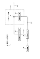
図1は、本発明の実施の形態に係る光ディスク装置を示すブロック図である。この光ディスク装置1は、ディスク原盤2を露光してディジタルオーディオテープレコーダ3より出力されるオーディオデータD1と、このオーディオデータD1の処理に必要な副データを記録する。光ディスクの製造工程では、このディスク原盤2を現像した後、電鋳処理することにより、マザーディスクを作成し、このマザーディスクよりスタンパーを作成する。さらに光ディスクの製造工程では、このようにして作成したスタンパーよりディスク状基板を作成し、このディスク状基板に反射膜、保護膜を形成してコンパクトディスクを作成する。
【0017】
すなわちこの光ディスク装置1において、スピンドルモータ4は、ディスク原盤2を回転駆動し、底部に保持したFG信号発生回路より、所定の回転角毎に信号レベルが立ち上がるFG信号FGを出力する。スピンドルサーボ回路5は、ディスク原盤2の露光位置に応じて、このFG信号FGの周波数が所定周波数になるようにスピンドルモータ4を駆動し、これによりディスク原盤2を線速度一定の条件により回転駆動する。
【0018】
記録用レーザー7は、ガスレーザー等により構成され、ディスク原盤露光用のレーザービームLを射出する。光変調器8Aは、電気音響光学素子で構成され、制御信号SC1に応じてレーザービームLの光量を切り換えて出力する。これにより光変調器8Aは、制御信号SC1に応じてレーザービームLの光量を変調する。
【0019】
光変調器8Bは、電気音響光学素子で構成され、このレーザービームLを変調信号S1によりオンオフ制御して射出する。ミラー10は、このレーザービームLの光路を折り曲げてディスク原盤2に向けて射出し、対物レンズ11は、このミラー10の反射光をディスク原盤2に集光する。これらミラー10及び対物レンズ11は、図示しないスレッド機構により、ディスク原盤2の回転に同期してディスク原盤2の外周方向に順次移動し、これによりレーザービームLによる露光位置を順次ディスク原盤2の外周方向に変位させる。
【0020】
これによりこの光ディスク装置1では、ディスク原盤2を回転駆動した状態で、ミラー10及び対物レンズ11の移動によりらせん状にトラックを形成し、このトラックに変調信号S1に対応して順次ピットを形成する。さらにこのとき制御信号SC1に応じてピット幅を変化させる。
【0021】
識別符号発生回路12は、この光ディスク装置1により作成されるコンパクトディスクを識別するための識別データを発生し、この識別データに応じて制御信号SC1の信号レベルを切り換える。これにより識別符号発生回路12は、変調器8Aより出力されるレーザービームLの光量を100〔%〕の光量から85〔%〕の光量に間欠的に立ち下げ、ディスク原盤2に形成されるピット幅を識別データに応じて変調する。
【0022】
変調回路14は、ディジタルオーディオテープレコーダ3より出力されるオーディオデータD1を受け、対応するサブコードデータをこのオーディオデータD1に付加する。さらに変調回路14は、このオーディオデータD1及びサブコードデータをコンパクトディスクのフォーマットに従ってデータ処理し、変調信号S2を生成する。すなわち変調回路14は、オーディオデータD1及びサブコードデータに誤り訂正符号を付加した後、インターリーブ処理、EFM変調処理する。これにより変調回路14は、ピット形成の基本周期Tに対して、この基本周期Tの整数倍の周期(周期3T〜11T)で信号レベルが変化するEFM変調信号S2を出力する。
【0023】
エッジ位置補正回路15A及び15Bは、EFM変調信号S2の変化パターンを検出し、この変化パターンに応じて再生時の符号間干渉を低減するように、EFM変調信号S2のタイミングを補正し、そのタイミング補正結果でなる変調信号S1A及びS1Bを出力する。このときエッジ位置補正回路15Aは、光変調器8Aより出力される100〔%〕光量のレーザービームLに対応する変調信号S1Aを出力するのに対し、エッジ位置補正回路15Bは、光変調器8Aより出力される85〔%〕光量のレーザービームLに対応する変調信号S1Bを出力する。
【0024】
すなわちこのようにしてレーザービームLの光量を100〔%〕の光量から85〔%〕光量に切り換えてピット幅を変調すると、その分再生信号の信号レベルも変化することになる。具体的には、それぞれ100〔%〕の光量及び85〔%〕の光量による場合について、図2及び図3に再生信号RFのアイパターンを示すように、再生信号RFの振幅W1及びW2が変化する。
【0025】
これを連続した波形として観察すると、図4に示すように、正しく再生信号を2値化するためのスライスレベルSL1及びSL2が、100〔%〕の光量による場合と、85〔%〕の光量による場合とで相違するようになる。すなわち100〔%〕の光量による部分と、85〔%〕の光量による部分とで、アシンメトリーが大きく変化するようになる。
【0026】
これにより100〔%〕の光量による場合の一定のスライスレベルSL1により再生信号RFを2値化すると、正しいタイミング(すなわち基本周期Tに同期したタイミング)により2値化信号を生成することが困難になり、再生クロックに大きなジッタが発生することになり、これによりコンパクトディスクに記録されたオーディオデータを正しく再生することが困難になる。さらに85〔%〕の光量による再生信号を、100〔%〕の光量について設定したスライスレベルSL1によりスライスした場合、例えば周期3Tの再生信号のように、再生信号の振幅が小さな場合には、2値化信号の信号レベル自体スライスレベルSL1を横切らなくなり、これによりジッタが増大するだけでなく、この2値化信号より生成する再生データにビット誤りが多発することになる。
【0027】
一般のコンパクトディスクプレイヤーにおいては、このようなアシンメトリーの変化に対応してスライスレベルを補正するスライスレベル自動調整回路を備えてはいるものの、急激な光量変化については対応することが困難で、結局レーザービームLの光量を切り換えた直後の部分で、非常に長いバーストエラーが発生する。
【0028】
このため光ディスク装置1において、エッジ位置補正回路15A及び15Bは、ディスク原盤2に形成されるピット長を補正して、それぞれ100〔%〕及び85〔%〕の光量における再生信号RFにおいて、図5に示すように、同一のスライスレベルにより再生信号を2値化して正しいタイミングにより2値化信号を生成できるように、変調信号S2のタイミングを補正してなる変調信号S1A及びS1Bを出力する。
【0029】
さらにこのときそれぞれEFM変調信号S2の変化パターンを検出し、この変化パターンに応じて、隣接符号からの符号間干渉を低減するように変調信号S1A及びS1Bを出力する。
【0030】
すなわちレーサビームLの光量が変化すれば、ピット幅が変化することにより、各光量における符号間干渉の程度も変化する。このことからエッジ位置補正回路15A及び15Bは、各光量において、符号間干渉による再生信号RFのジッタが低減するように変調信号S2のタイミングを補正する。
【0031】
データセレクタ13は、識別符号発生回路12より出力される制御信号SC1に基づいて、レーザービームLの光量の切り換えに連動して対応する変調信号S1A及びS1Bを選択出力する。
【0032】
図6は、識別符号発生回路12を示すブロック図である。この識別符号発生回路12において、発振器18は、ピット形成周期に比して充分に長い周期(数百〜数千ピット周期)で信号レベルが切り換わる識別符号用クロックを生成する。N進カウンタ19は、この識別符号用クロックをカウントするリングカウンタでなり、カウント値CT1を出力し、カウント値が一巡するとリセット信号RSTを出力する。
【0033】
識別データテーブル20は、ビット情報を保持するリードオンメモリ回路で構成され、カウント値CT1をアドレス入力にして保持したデータを出力する。これにより識別データテーブル20は、同期信号として使われる一定のパターン情報をビット情報、ディスク原盤2に記録するID情報、製造工場などの情報を順次循環的に出力する。
【0034】
スクランブル回路21は、識別データテーブル20より出力されるビット情報をイクスクルーシブオア回路構成の加算回路23に入力し、ここでM系列発生回路22より出力されるM系列符号により暗号化して出力する。ここでM系列発生回路22は、複数のフリップフロップとイクスクルーシブオア回路により構成され、リセット信号RSTを基準にしてM系列符号をリセットする。これによりスクランブル回路21は、識別データテーブル20より順次循環的に出力されるビット情報に対応して、順次循環的にビット値の変化する制御信号SC1を出力する。なおM系列発生回路22は、リセット信号RSTが出力された後、所定期間はM系列符号の出力を停止し、これにより識別データテーブル20より出力されるビット情報のうち、同期信号の部分にはスクランブル処理しないようになされている。
【0035】
かくしてこの光ディスク装置1では、この制御信号SC1に応じてレーザービームLの光量が100〔%〕の光量から85〔%〕の光量に切り換えられることにより、コンパクトディスクのピット幅により、M系列符号で暗号化されたID情報等が同期信号と共に記録されるようになされている。
【0036】
図7は、エッジ位置補正回路15Aを示すブロック図である。なおエッジ位置補正回路15Bは、立ち上がりエッジ補正回路25A及び25Bに格納する補正データが異なる以外、エッジ位置補正回路15Aと同一でなることにより、重複した説明は省略する。
【0037】
エッジ位置補正回路15Aにおいて、レベル変換回路26は、出力振幅が1〔V〕でなるEFM変調信号S2の信号レベルを、出力振幅が5〔V〕でなるTTLレベルに補正して出力する。PLL回路27は、図8に示すように、レベル変換回路26より出力される変調信号S3(図8(A))よりクロックCK(図8(B))を生成して出力する。かくするにつき、変調信号S2においては、基本周期Tの整数倍の周期で信号レベルが変化することにより、PLL回路27は、この変調信号S2に同期した基本周期Tにより信号レベルが変化するクロックCKを生成する。
【0038】
立ち上がりエッジ補正回路25Aは、図9に示すように、クロックCKで動作する13個のラッチ回路28A〜28Mを直列に接続し、この直列回路にレベル変換回路26の出力信号S3を入力する。これにより立ち上がりエッジ補正回路25Aは、レベル変換回路26の出力信号S3をクロックCKのタイミングによりサンプリングし、連続する13点のサンプリング結果より、変調信号S2の変化パターンを検出する。すなわち、例えば「0001111000001 」のラッチ出力が得られた場合、長さ5Tのスペースに続いて長さ4Tのピットが連続する変化パターンと判断することができる。同様に「0011111000001 」のラッチ出力が得られた場合、長さ5Tのスペースに続いて長さ5Tのピットが連続する変化パターンと判断することができる。
【0039】
補正値テーブル29は、複数の補正データを格納したリードオンリメモリで形成され、ラッチ回路28A〜28Mのラッチ出力をアドレスにして、変調信号S3の変化パターンに対応する補正値データDFを出力する。モノステーブルマルチバイブレータ(MM)30は、直列接続された13個の中央のラッチ回路28Gよりラッチ出力を受け、このラッチ出力の立ち上がりのタイミングを基準にして、所定期間の間(周期3Tより充分に短い期間)、信号レベルが立ち上がる立ち上がりパルス信号を出力する。
【0040】
遅延回路31は、12段のタップ出力を有し、各タップ間の遅延時間差がこのエッジ位置補正回路15Aにおける変調信号のタイミング補正の分解能に設定される。遅延回路31は、モノステーブルマルチバイブレータ30より出力される立ち上がりパルス信号を順次遅延して各タップより出力する。セレクタ33は、補正値データDFに従って遅延回路31のタップ出力を選択出力し、これにより補正値データDFに応じて遅延時間の変化してなる立ち上がりパルス信号SS(図8(D))を選択出力する。
【0041】
これにより立ち上がりエッジ補正回路25Aは、変調信号S2の信号レベルの立ち上がりに対応して信号レベルが立ち上がり、かつ変調信号S2に対する各立ち上がりエッジの遅延時間Δr(3,3)、Δr(4,3)、Δr(3,4)、Δr(5,3)、……が、変調信号S2の変化パターンに応じて変化する立ち上がりエッジ信号SSを生成する。
【0042】
なおこの図8においては、変調信号S2の変化パターンを、クロック(すなわちチャンネルクロックでなる)CKの1周期を単位としたピット長pと、ピット間隔bとにより表し、立ち上がりエッジに対する遅延時間をΔr(p、b)により示す。従ってこの図8(D)において、2番目に記述された遅延時間Δr(4、3)は、長さ4クロックのピットの前に、3クロックのブランクがある場合の遅延時間である。これにより補正値テーブル29には、これらp及びbの全ての組合せに対応する補正値データDFが格納されていることになる。
【0043】
かくするにつき光ディスクでは、変調信号S2に応じてレーザービームLが照射されてピットが形成されることにより、立ち上がりエッジ補正回路25Aは、基本周期Tを単位にした周期12Tの範囲について、光ディスクに形成されるピットのパターンを検出し、このパターンに応じて立ち上がりエッジ信号SSを生成することになる。
【0044】
立ち下がりエッジ補正回路25Bは、モノステーブルマルチバイブレータ30がラッチ出力の立ち下がりエッジを基準にして動作することと、補正値テーブル29の内容が異なることを除いて、立ち上がりエッジ補正回路25Aと同一に構成される。
【0045】
これにより立ち下がりエッジ補正回路25Bは、変調信号S2の信号レベルの立ち下がりに対応して信号レベルが立ち上がり、かつ変調信号S2に対する各立ち上がりエッジの遅延時間Δf(3,3)、Δf(4,4)、Δf(3,3)、Δf(5,4)、……が変調信号S2の変化パターンに応じて変化する立ち下がりエッジ信号SR(図8(C))を生成する。なおこの図8においては、立ち上がりエッジに対する遅延時間と同様に、ピット長pと、ピット間隔bとにより、立ち下がりエッジに対する遅延時間をΔf(p、b)で示す。
【0046】
かくするにつき立ち下がりエッジ補正回路25Bにおいても、基本周期Tを単位にした周期12Tの範囲について、光ディスクに形成されるピットのパターンを検出し、このパターンに応じてレーザービームの照射終了のタイミングでなる変調信号S2の立ち下がりエッジのタイミングを補正して、立ち下がりエッジ信号SRを生成するようになされている。
【0047】
フリップフロップ(F/F)35(図7)は、立ち上がりエッジ信号SS及び立ち下がりエッジ信号SRを合成して出力する。すなわちフリップフロップ35は、立ち上がりエッジ信号SS及び立ち下がりエッジ信号SRをそれぞれセット端子S、リセット端子Rに入力し、これにより立ち上がりエッジ信号SSの信号レベルの立ち上がりで信号レベルが立ち上がった後、立ち下がりエッジ信号SRの信号レベルの立ち上がりで信号レベルが立ち下がる変調信号S5を生成する。レベル逆変換回路36は、出力振幅がTTLレベルでなるこの変調信号S5の信号レベルを補正し、元の出力振幅により出力する。
【0048】
これにより変調信号S2においては、立ち上がりエッジ及び立ち下がりエッジのタイミングが前後のピット及びランドの長さに応じて補正されて出力され、これに対応してディスク原盤2に対してレーザービームLを照射するタイミングも、前後のピット及びランドの長さに対応して補正される。
【0049】
これにより光ディスク装置1では、再生時、符号間干渉により発生するジッタを低減するように、各ピットの前エッジ及び後エッジの位置を補正する。またそれぞれ記録用レーザービームLの光量に対応したエッジ位置補正回路15A及び15Bにより、前エッジ及び後エッジの位置を補正することにより、レーザービームLの光量を立ち上げた場合でも、再生信号を一定のしきい値により処理して、ピット長、ピット間隔により記録したデータD1を確実に再生できるように、各ピットの前エッジ及び後エッジの位置を補正する。
【0050】
すなわちレーザービームLの光量が100〔%〕の場合には、エッジ位置補正回路15Aより出力される変調信号S1Aにより前エッジ及び後エッジの位置を補正し、これにより一定のスライスレベルにより正しく2値化信号を生成できるようにし、またレーザービームLの光量が85〔%〕の場合には、エッジ位置補正回路15Bより出力される変調信号S1Bにより前エッジ及び後エッジの位置を補正し、100〔%〕の場合と同一のスライスレベルにより正しく2値化信号を生成できるようにする。
【0051】
図10は、このようにしてエッジのタイミング補正に使用される補正値テーブル29の生成の説明に供する工程図である。光ディスク装置1では、この補正値テーブル29を適切に設定することにより、レーザービームLの光量、ピット長、前後のブランク長が変化した場合でも、クロックCKに同期した正しいタイミングで所定のスライスレベルを再生信号が横切るようにする。
【0052】
なお補正値テーブル29は、各エッジ位置補正回路15A及び15Bにおいて、それぞれ立ち上がりエッジ補正回路25A及び立ち下がりエッジ補正回路25Bに設定されるが、生成の条件が異なる以外、何れも生成方法は同一であるので、ここでは立ち上がりエッジ補正回路25Aについて説明する。
【0053】
この工程においては、光ディスク装置1により評価用のディスク原盤を作成し、このディスク原盤より作成されるコンパクトディスクの再生結果に基づいて、補正値テーブルを設定する。
【0054】
ここでこの評価用のディスク原盤作成時において、光ディスク装置1には、評価基準用の補正値テーブル29が設定される。この評価基準用の補正値テーブル29は、セレクタ33(図9)において、常に遅延回路31のセンタータップ出力を選択出力するように、補正値データDFが設定されて形成される。これによりこの工程では、100〔%〕のレーザー出力によりEFM変調信号S3で直接光変調器8Bを駆動した場合と同一の条件により、すなわち通常のコンパクトディスク作成工程と同一の条件によりディスク原盤2を露光する。
【0055】
この工程では、このようにして露光したディスク原盤2を現像した後、電鋳処理してマザーディスクを作成し、このマザーディスクよりスタンパー40を作成する。さらにこのスタンパー40より通常のコンパクトディスク作成工程と同様に、コンパクトディスク41を作成する。
【0056】
コンパクトディスクプレイヤー(CDプレイヤー)42は、このようにして作成した評価用のコンパクトディスク41を再生する。このときコンパクトディスクプレイヤー42は、コンピュータ44により制御されて動作を切り換え、コンパクトディスク41より得られる戻り光の光量に応じて信号レベルが変化する再生信号RFを内蔵の信号処理回路よりディジタルオシロスコープ45に出力する。かくするにつき、このコンパクトディスク41は、レーザービームLの光量の切り換えに伴ってピット幅が変化していることにより、ディジタルオシロスコープ45で再生信号RFを観察すると、ピットに対応する部分で再生信号の振幅が変化して観察される。
【0057】
またこのピット幅の変化に伴ってピットの前エッジ、後エッジが変化していることにより、振幅の変化に伴って大きなジッタが観察され、アシンメトリーも大きく変化することになる。さらにユーザーエリア等の低レベルのレーザービームによりピットを形成した部分においても、前後のピットからの符号間干渉によるジッタが観察されことになる。
【0058】
ディジタルオシロスコープ45は、コンピュータ44により制御されて動作を切り換え、チャンネルクロックの20倍のサンプリング周波数でこの再生信号RFをアナログディジタル変換処理し、その結果得られるディジタル信号をコンピュータ44に出力する。
【0059】
コンピュータ44は、ディジタルオシロスコープ45の動作を制御する共に、ディジタルオシロスコープ45より出力されるディジタル信号を信号処理し、これにより補正値データDFを順次計算する。さらにコンピュータ44は、ROMライター46を駆動して、計算した補正値データDFを順次リードオンリメモリに格納し、これにより補正値テーブル29を形成する。この工程では、この補正値テーブル29により最終的に光ディスクを製造する。
【0060】
図11は、このコンピュータ44における処理手順を示すフローチャートである。この処理手順において、コンピュータ44は、ステップSP1からステップSP2に移り、ジッタ検出結果Δr(p,b)、ジッタ計測回数n(p,b)を値0にセットする。ここでコンピュータ44は、ジッタ検出対象でなるエッジの前後について、ピット長p、ピット間隔bの組合せ毎に、ジッタ検出結果Δr(p,b)を算出し、またジッタ計測回数n(p,b)をカウントする。このためコンピュータ44は、ステップSP2において、これら全てのジッタ検出結果Δr(p,b)、ジッタ計測回数n(p,b)を初期値にセットする。
【0061】
続いてコンピュータ44は、ステップSP3に移り、ディジタルオシロスコープ45より出力されるディジタル信号を所定のスライスレベルと比較することにより、再生信号RFを2値化してなるディジタル2値化信号を生成する。なおコンピュータ44は、この処理において、スライスレベル以上が値1、スライスレベルに満たない部分では値0となるように、ディジタル信号を2値化する。
【0062】
続いてコンピュータ44は、ステップSP4に移り、このディジタル信号でなる2値化信号より再生クロックを生成する。ここでコンピュータ44は、2値化信号を基準にして演算処理によりPLL回路の動作をシミュレーションし、これにより再生クロックを生成する。
【0063】
さらにコンピュータ44は、続くステップSP5において、このようにして生成した再生クロックの各立ち下がりエッジのタイミングで、2値化信号をサンプリングし、これにより変調信号を復号する(以下復号したこの変調信号を復号信号と呼ぶ)。
【0064】
続いてコンピュータ44は、ステップSP6に移り、2値化信号の立ち上がりエッジの時点から、このエッジに最も近接した再生クロックの立ち下がりの時点までの時間差eを検出し、これによりこのエッジにおけるジッタを時間計測する。続いてコンピュータ44は、ステップSP7において、ステップSP6で時間計測したエッジについて、復号信号より前後のピット長p及びピット間隔bを検出する。
【0065】
コンピュータ44は、続いてステップSP8において、前後のピット長p及びピット間隔bに対応するジッタ検出結果Δr(p,b)に対して、ステップSP6において検出した時間差eを加算し、また対応するジッタ計測回数n(p,b)を値1だけインクリメントする。続いてコンピュータ44は、ステップSP9に移り、全ての立ち上がりエッジについて、時間計測を完了したか否か判断し、ここで否定結果が得られると、ステップSP5に戻る。
【0066】
これによりコンピュータ44は、ステップSP5−SP6−SP7−SP8−SP9−SP5の処理手順を繰り返し、再生信号RFに表れる変化パターン毎に、時間計測したジッタ検出結果を累積加算し、また加算数をカウントする。なおこの変化パターンは、立ち上がりエッジ補正回路25Aにおけるラッチ回路28A〜28Mの段数に対応するように、ジッタ検出対象のエッジより基本周期Tを基準にした前後6サンプルの期間(全体で周期12Tの期間)により分類される。
【0067】
このようにして全てのエッジについて、ジッタの時間計測を完了すると、コンピュータ44は、ステップSP9において肯定結果が得られることにより、ステップSP10に移り、ここで再生信号RFに表れる変化パターン毎に、時間計測したジッタ検出結果を平均値化する。すなわちステップSP6において検出されるジッタにおいては、ノイズの影響を受けていることにより、コンピュータ44は、このようにしてジッタ検出結果を平均値化し、ジッタの測定精度を向上する。
【0068】
コンピュータ44は、このようにしてジッタ検出結果を平均値化すると、続いてステップSP11に移り、この検出結果より、各変化パターン毎にそれぞれ補正値データDFを生成し、各補正値データDFをROMライター46に出力する。ここでこの補正値データDFは、遅延回路31におけるタップ間の遅延時間差をτとおいて、次式の演算処理を実行して算出される。
【0069】
【数1】

なおここでHr1(p,b)は、補正値データDFにより選択される遅延回路31のタップであり、値0の場合がセンタータップである。またHr0(p,b)は、初期値でなる補正値データDFにより選択される遅延回路31のタップであり、この実施の形態において、Hr0(p,b)は、値0に設定されていることになる。またaは定数である。ここでこの実施の形態において、aは1以下の値(例えば0.7など)に設定され、これによりノイズなどの影響があっても、確実に補正値データを収束させるようになされている。
【0071】
コンピュータ44は、ディジタルオシロスコープ45を介して検出される再生信号RFの信号レベルを基準にして、レーザービームLの光量を立ち上げた場合と、通常の光量の場合とでそれぞれ上述した補正値データの生成処理を実行し、これによりレーザービームLの光量を立ち上げた場合でも、通常のスライスレベルにより再生信号RFを2値化して、正しいタイミングにより2値化信号を生成できるように補正値データDFを生成する。
【0072】
コンピュータ44は、このようにして生成した補正値データDFをROMライター46に格納すると、ステップSP12に移ってこの処理手順を終了する。続いてコンピュータ44は、同様の処理手順をディジタル2値化信号の立ち下がりエッジについて実行し、これにより補正値テーブル29を完成する。
【0073】
図12は、このようにして製造されたコンパクトディスクの再生装置を示すブロック図である。このコンパクトディスクプレイヤー50は、サーボ回路51によりスピンドルモータMをスピンドル制御すると共に、光ピックアップ9をトラッキング制御、フォーカス制御した状態で、コンパクトディスクHに光ピックアップPよりレーザービームを照射する。さらにコンパクトディスクプレイヤー50は、このレーザービームの戻り光を光ピックアップPで受光し、この戻り光の光量に応じて信号レベルが変化する再生信号RFを生成する。
【0074】
2値化回路52は、この再生信号RFを波形等化した後、所定のしきい値により信号レベルを識別して2値化信号S7を出力する。PLL回路53は、この2値化信号S7を基準にして再生クロック(チャンネルクロック)CKを生成して出力する。
【0075】
ここで再生信号RFは、光ディスク装置1において、各種ピット形成のパターンに応じてレーザービーム照射のタイミングが補正されて、各ピットの前エッジ及び後エッジのタイミングが補正されてなることにより、極めて小さなジッタにより再生される。さらに間欠的にレーザービームの光量を立ち上げてピット幅を変調したことにより、間欠的に振幅が増大することになる。さらにピット幅の変化に対応してレーザービーム照射のタイミングが補正されて、このようにレーザービームの光量を立ち下げた部分においても、各ピットの前エッジ及び後エッジのタイミングが補正されてなることにより、他の部分と等しいアシンメトリーにより再生される。
【0076】
これにより2値化回路52においては、記録時における基本周期Tに対応した正しいタイミングにより2値化信号S7を生成することになり、またPLL回路53においては、ジッタの極めて少ない再生クロックCKを生成して出力することになる。
【0077】
EFM復調回路54は、再生クロックCKを基準にして2値化信号を順次ラッチすることにより再生データを生成する。さらにEFM復調回路54は、この再生データを復調して出力する。ECC回路55は、EFM復調回路54より出力される再生データをデインターリーブ処理した後、誤り訂正処理して出力する。
【0078】
識別符号検出回路56は、再生信号RFの振幅より識別データを検出してシステム制御回路77に出力する。すなわち図13に示すように、識別符号検出回路56は、ピット検出回路57において、周期6T〜周期11Tのピットを検出する。ここでピット検出回路57は、図14に示すように、直列接続した10段のラッチ回路57A〜57Jに2値化信号S7を入力し、この2値化信号S7を再生クロックCKにより順次転送する。アンド回路58A〜58Fは、所定の入力端が反転入力端に設定され、ラッチ回路57A〜57Jのラッチ出力を入力し、それぞれ周期6T、7T、8T、……のピットに対応してラッチ回路57A〜57Jのラッチ出力が値1又は値0にセットされると、出力信号の論理レベルを立ち上げる。オア回路59は、アンド回路58A〜58Fの出力信号を受け、その論理和信号を出力する。これによりピット検出回路57は、ピット形成時におけるレーザービームの光量が正確に振幅に反映されてなるピット長の長いピットを検出する。
【0079】
識別符号検出回路56(図13)において、アナログディジタル変換回路(A/D)ADは、再生信号RFをアナログディジタル変換処理し、ディジタル再生信号DRFを出力する。遅延回路61は、このディジタル再生信号DRFを遅延し、ピット検出回路57におけるピット検出のタイミングに対応するタイミングにより出力する。
【0080】
ラッチ回路Rは、ピット検出回路57の検出結果に基づいてディジタル再生信号DRFをラッチし、これにより周期6T以上ピットについて、各ピットのほぼ中央より戻り光が得られるタイミングで、再生信号RFの振幅を検出する。ディジタルアナログ変換回路DAは、このラッチ回路Rのラッチ結果をディジタルアナログ変換処理して出力する。2値化回路60は、ディジタルアナログ変換回路DAの出力信号を2値化して2値化信号を生成する。
【0081】
PLL回路61は、この2値化信号より再生クロックを検出する。同期検出回路62は、この2値化信号の信号レベルを監視することにより、光ディスク装置1の識別符号発生回路12において付加した同期信号のタイミングを検出して出力する。M系列発生回路63は、この同期検出回路62により検出されたタイミングによりリセットされた後、M系列符号を順次出力する。逆スクランブル回路64は、イクスクルーシブオア回路構成の加算回路65により、このM系列符号と2値化信号とを論理演算処理し、これにより識別データDC1を復調する。
【0082】
システム制御回路77(図12)は、このコンパクトディスクプレイヤー50全体の動作を制御するコンピュータにより構成され、識別符号検出回路56において正しく識別データが検出されたか否か判断し、ここで否定結果が得られるとディジタルアナログ変換回路79の動作を停止制御する。ここでディジタルアナログ変換回路79は、システム制御回路77の制御によりECC回路55より出力されるオーディオデータをディジタルアナログ変換処理し、アナログ信号でなるオーディオ信号SAを出力する。
【0083】
以上の構成において、光ディスク装置1においては(図1、図9)、エッジ位置補正回路15A及び15Bにおける補正値テーブル29を初期値に設定して、従来のコンパクトディスクの作成条件と同一の条件により評価用のディスク原盤2が作成され、このディスク原盤2より評価用のコンパクトディスク41が作成される(図10)。
【0084】
この評価用のコンパクトディスク41は、基本周期Tの整数倍の周期で信号レベルが変化する変調信号によりレーザービームLがオンオフ制御されてディスク原盤2が順次露光され、これによりピット長及びピット間隔によりオーディオデータD1等が記録される。また識別データに基づいてレーザービームLの光量が立ち下げられ、これによりピット幅の変化により識別データが記録される。さらにこのピット幅の変化に伴い、ピット長が変化して形成される。
【0085】
これによりこの評価用のコンパクトディスク41より得られる再生信号は、一定の光量によりピットが形成されている部分では、隣接ピットの符号間干渉によりジッタが観察されることになる。またピット幅が変化する部分については、隣接ピットの符号間干渉に加えてピット長の変化により、大きなジッタが発生することになる。またこのピット幅が変化する部分については、再生信号の振幅が大きく変化し、アシンメトリーも激しく変化することになる。
【0086】
従ってこのコンパクトディスク41より得られる再生信号は、前後のピット及びランドの形状に対応する変調信号の変化パターン、露光時のレーザービーム光量に応じて、スライスレベルを横切るタイミングが変化し、この再生信号より生成される再生クロックにおいては大きなジッタが発生することになる。
【0087】
このコンパクトディスク41は、コンパクトディスクプレイヤー42により再生され、再生信号RFがディジタルオシロスコープ45によりディジタル信号に変換された後、コンピュータ44により2値化信号、EFM復号信号、再生クロックが生成される。さらにコンパクトディスク41は、2値化信号の各エッジ毎に、復号信号より前後のピット及びランドが検出されて変調信号の変化パターンが検出され、各変化パターン毎に、再生クロックに対する各エッジのジッタ量が時間計測される。
【0088】
さらにレーザービームの光量を立ち上げた場合と、一定値に保持した場合とで、これら時間計測結果が各変化パターン毎に平均値化され、レーザービームの各光量によるジッタ量が符号間干渉によるジッタ量と共に各変化パターン毎に検出される。コンパクトディスク41は、このようにして検出したジッタ量により、遅延回路31(図9)のタップ間遅延時間差τを基準にした(1)式の演算処理が実行され、遅延回路31のセンタータップを基準にして、この検出したジッタ量を打ち消すことができる遅延回路31のタップ位置が検出される。さらにコンパクトディスク41は、この検出したタップ位置を特定するデータが補正値データDFとしてリードオンリメモリに格納され、これにより遅延回路31のタップ間遅延時間差τをジッタ補正単位に設定して、補正値テーブル29が形成される。
【0089】
このとき100〔%〕のレーザービーム光量に対応する補正値データDFが、エッジ位置補正回路15Aの補正値テーブル29に記録され、また85〔%〕のレーザービーム光量に対応する補正値データDFが、エッジ位置補正回路15Bの補正値テーブル29に記録される。
【0090】
このようにして補正値テーブル29が形成されると、光ディスク装置1では、オーディオデータD1が所定のデータ処理を受け、基本周期Tを単位にして信号レベルの変化する変調信号S2に変換される。この変調信号S2は、エッジ位置補正回路15Aにおいて(図7)、信号レベルがTTLレベルに変換された後、PLL回路27によりクロックCKが再生される。またそれぞれ立ち上がりエッジ補正回路25A及び立ち下がりエッジ補正回路25Bにおいて(図9)、13段のラッチ回路28A〜28Mで順次ラッチされて、変化パターンが検出される。
【0091】
さらに変調信号S2は、このラッチ回路28A〜28Mの中間のラッチ回路28Gよりモノステーブルマルチバイブレータ30に入力され、立ち上がりエッジ補正回路25Aにおいては、立ち上がりエッジのタイミングで、立ち下がりエッジ補正回路25Bにおいては、立ち下がりエッジのタイミングで、モノステーブルマルチバイブレータ30の出力をトリガし、それぞれ立ち上がりエッジ及び立ち下がりエッジのタイミングで信号レベルが立ち上がる立ち上がりパルス信号及び立ち下がりパルス信号を生成する。
【0092】
これら立ち上がりパルス信号及び立ち下がりパルス信号は、それぞれ立ち上がりエッジ補正回路25A及び立ち下がりエッジ補正回路25Bの遅延回路31において、補正値データDFの算出に利用された遅延時間τを単位にして順次遅延され、この遅延回路31のタップ出力がセレクタ33に出力される。これに対してラッチ回路28A〜28Mで検出された変調信号S2の変化パターンは、ラッチ回路28A〜28Mのラッチ出力をアドレスにした補正値テーブル29のアクセスにより、対応する補正値データDFが検出され、この補正値データDFによりセレクタ33の接点が切り換えられる。
【0093】
これによりそれぞれ立ち上がりエッジ補正回路25A及び立ち下がりエッジ補正回路25Bのセレクタ33より、評価用のコンパクトディスク41で検出されたレーザービームLを100〔%〕の光量により照射した場合のジッタを補正するように、変調信号S2の立ち上がりエッジ及び立ち下がりエッジのタイミングをそれぞれ補正してなる立ち上がりエッジ信号SS及び立ち下がりエッジ信号SRが出力され、これら立ち上がりエッジ信号SS及び立ち下がりエッジ信号SR(図7)が、フリップフロップ35により合成される。
【0094】
さらにこのフリップフロップ35の出力信号S5がレベル逆変換回路36により信号レベルの補正を受け、これにより評価用のコンパクトディスク41で検出した、レーザービームLを100〔%〕の光量により照射した場合のジッタを補正するように、すなわち符号間干渉を低減するように、変調信号S2のエッジのタイミングを補正してなる変調信号S1Aが生成される。
【0095】
同様にして、変調信号S2は、エッジ位置補正回路15Bにおいて、変化パターンが検出され、この変化パターンに対応する補正値データDFにより立ち上がりエッジ信号SS及び立ち下がりエッジ信号SRが生成され、これら立ち上がりエッジ信号SS及び立ち下がりエッジ信号SRがフリップフロップ35により合成される。これにより変調信号S2は、エッジ位置補正回路15Bにおいて、評価用のコンパクトディスク41で検出したレーザービームLを85〔%〕の光量により照射した場合のジッタを補正するように、すなわちレーザービーム光量の立ち下げに伴うピット長の変化を打ち消すように、また符号間干渉を低減するように、変調信号S2のエッジのタイミングを補正してなる変調信号S1Bが生成される。
【0096】
これに対して光ディスク装置1では、識別データテーブル20(図6)より、同期信号、識別データ等が順次循環的に出力され、これらのデータがスクランブル回路21において、M系列符号により暗号化される。さらにこの暗号化された識別データ等による制御信号SC1が光変調器8A(図1)に入力される。これにより光ディスク装置1では、識別データ等に応じてレーザービームLの光量が100〔%〕の光量より85〔%〕の光量に切り換えられ、この光量の切り換えにより識別データ等がピット幅の変化によりディスク原盤2に記録される。
【0097】
このときデータセレクタ13において、この光量の切り換えに連動して、エッジ位置補正回路15A及び15Bより出力される変調信号S1A及びS1Bが選択的に光変調器8Bに入力され、これによりディスク原盤2においては、ピット長及びピット間隔によりオーディオデータD1が記録され、このとき識別データ等に応じたピット幅の変化に伴うピット長の変化を防止するように露光のタイミングが補正される。また各ピットについて、隣接ピットによる符号間干渉を低減するように露光のタイミングが補正される。
【0098】
このようにしてディスク原盤2が露光されると、このディスク原盤2よりコンパクトディスクHが生産され、このコンパクトディスクHがコンパクトディスクプレイヤー50(図12)により再生される。このコンパクトディスクHは、オーディオデータD1が隣接ピットからの符号間干渉を低減するように、隣接ピットとの組み合わせによるパターに応じて前エッジ及び後エッジの位置が補正されて、ピット長及びピット間隔により記録されることになる。さらに暗号化された識別データがピット幅の変化により記録され、オーディオデータD1においては、さらにこのピット幅の変化によるピット長の変化を打ち消すように、前エッジ及び後エッジの位置が補正されていることになる。
【0099】
コンパクトディスクプレイヤー50においては、このようにして生産されたコンパクトディスクHより戻り光の光量に応じて信号レベルが変化する再生信号RFを検出し、再生信号RFが、2値化回路52において、所定のスライスレベルによりスライスされ、2値化信号S7に変換される。さらにこの2値化信号S7よりPLL回路53において再生クロックCKが生成され、EFM復調回路54において、この再生クロックCKにより2値化信号S7が順次ラッチされて再生データが生成された後、復調される。さらにこの再生データが続くECC回路55においてデインターリーブ処理、誤り訂正処理され、アナログ信号に変換されて出力される。
【0100】
この一連の処理において、この実施の形態に係るコンパクトディスクHでは、ピット幅の変化によるピット長の変化を打ち消すように、前エッジ及び後エッジの位置が補正されていることにより、一定のスライスレベルSLにより再生信号RFを2値化して、正しいタイミングにより2値化信号を生成することができる。すなわち光量の切り換えに伴う再生クロックCKのジッタを有効に回避することができるように、2値化信号を生成することができる。さらに符号間干渉についても、これを低減するようにエッジの位置が補正されていることにより、符号間干渉によるジッタも低減することができる。これによりピット幅を変化させたにも係わらず、オーディオデータを正しく再生することができる。
【0101】
また2値化信号S7は、再生信号RF、再生クロックCKと共に識別符号検出回路56に入力され、ここでピット幅の変化により記録された識別データが再生される。すなわち識別符号検出回路56において(図13)、2値化信号S7は、ピット検出回路57において周期6T以上のピットのタイミングが検出され、このタイミングによりラッチ回路Rで信号レベルが検出される。さらにこの信号レベルが2値化回路60により判定され、暗号化されてなる識別データが再生される。この識別データは、PLL回路61によりクロックが再生され、このクロックを基準にしてM系列データにより暗号化が解除される。
【0102】
コンパクトディスクプレイヤー50においては、システム制御回路77において、この識別データが正しく再生されたか否か判断されることにより、コンパクトディスクHが正規の品物か否か判断され、正規のコンパクトディスクにおいては、ディジタルアナログ変換回路79よりオーディオ信号SAが出力されるのに対し、コピー品の場合、オーディオ信号SAの出力が停止される。
【0103】
すなわちこの種のコンパクトディスクプレイヤー50で再生したオーディオデータD1を記録して生成されるコピーのコンパクトディスクについては、ピット幅を制御して識別データを記録することが困難で、結局コンパクトディスクプレイヤー側で識別データを再生することが困難になる。またこの識別データ自体暗号化されていることにより、容易に解読することが困難になる。これによりこのようなコピーについては、コンパクトディスクプレイヤー50側で再生困難にすることができ、市場より駆逐することができる。
【0104】
また正規品でなるコンパクトディスクHより物理的にピット形状を転写してコンパクトディスクをコピーする場合、ピット形状の物理的な変化を避け得ず、これにより補正したエッジ位置、さらにはピット幅の変化を正確に再現することが困難になる。これによりこの種のコピーによるコンパクトディスクは、再生信号RFを2値化して正しいタイミングにより2値化信号S7の信号レベルが変化しなくなり、その分再生クロックCKにジッタが発生し、さらには再生データに誤り訂正困難なビット誤りが発生する。これによりコンパクトディスクプレイヤー50では、この種のコピーによるコンパクトディスクを再生することが困難になる。
【0105】
また正しくピット幅をコピーすることが困難なことにより、コンパクトディスクプレイヤー側で、正しい識別データを検出することも困難になり、これによっても再生困難にすることができる。
【0106】
以上の構成によれば、主のデータでなるオーディオデータD1をピット長及びピット間隔により記録すると共に、コンパクトディスクの識別データを暗号化してピット幅により記録することにより、違法なコピーについては、再生装置側で容易に識別して再生困難に設定することができ、この種の違法なコピーを排除することができる。
【0107】
またこのときピット幅に伴うピット長の変化を補正するように、さらには隣接ピットによる符号化干渉を低減するように、各ピットのエッジを補正することにより、所望のデータを高密度に記録した場合でも、オーディオデータを確実に再生して、違法なコピーについては確実に排除することができ、この種の違法なコピーを排除することができる。
【0108】
さらに周期6T以上のピットについて、選択的に再生信号の信号レベルを検出してピット幅により記録した識別データを再生することにより、ピット幅の変化に伴う再生信号の信号レベルの変化を確実に検出して、正しく識別データを再生することができる。
【0109】
なお上述の実施の形態においては、オーディオデータを記録するピットの幅を変化させて識別データを記録する場合について述べたが、本発明はこれに限らず、例えばリードインエリアにおいてTOCのデータを記録するピットの幅を変化させて識別データを記録してもよい。
【0110】
また上述の実施の形態においては、ピット幅により暗号化した識別データを記録する場合について述べたが、本発明はこれに限らず、必要に応じて暗号化することなく直接識別データを記録してもよい。また識別データの暗号化に使用した符号化データを併せてピット幅により記録してもよい。
【0111】
さらに上述の実施の形態においては、オーディオデータを単に符号化処理して記録する場合について述べたが、本発明はこれに限らず、暗号化したオーディオデータ等を記録する場合にも適用することができ、この場合には暗号化に使用した符号化データを併せてピット幅により記録してもよい。
【0112】
また上述の実施の形態においては、光ディスクの識別データを製造箇所等のデータと共にピット幅により記録する記録する場合について述べたが、本発明はこれに限らず、コンパクトディスクに記録する各著作物の識別データを併せて又は単独で記録する場合、さらには製造メーカー等の識別データを併せて又は単独で記録する場合等に広く適用することができる。
【0113】
さらに上述の実施の形態においては、周期6T以上のピットについて、再生信号の信号レベルを検出する場合について述べたが、本発明はこれに限らず、実用上充分にピット幅の変化を識別できる場合、これ以外のピットについて再生信号の信号レベルを検出しても良く、さらにはこれとは逆に、例えば物理的なコピーにより著しくピット幅の変化する特定周期のピットについてだけ再生信号の信号レベルを検出してもよい。
【0114】
また上述の実施の形態においては、連続するピット列に対して、充分に長い時間間隔によりレーザービームの光量を切り換える場合について述べたが、本発明はこれに限らず、実用上充分にピット幅の変化を識別できる場合、特定ピットについてだけレーザービームの光量を切り換え、これにより例えば連続するピット毎にレーザービームの光量を切り換えてピット幅を変調してもよい。
【0115】
さらに上述の実施の形態においては、レーザービームの光量を2段階で切り換えてピット幅を変調する場合について述べたが、本発明はこれに限らず、実用上充分にピット幅の変化を識別できる場合、レーザービームの光量を多段階で切り換えてピット幅を変調してもよい。
【0116】
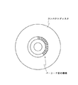
また上述の実施の形態においては、単にピット幅の変化により識別データを繰り返し記録する場合について述べたが、本発明はこれに限らず、このピット幅の変化による識別データの記録を、レーザービーム照射位置に応じて所定領域についてだけ実行してもよい。この場合、例えばコンパクトディスクの回転に同期したタイミングで、ピット幅の変化により識別データを記録すれば、図15に示すように、コンパクトディスクの反射面において、放射状に広がるバーコード状の模様を形成することができ、この模様の有無により違法コピーか否かを肉眼で判定することができる。またメーカー名等の模様を反射面に形成することもできる。
【0117】
さらに上述の実施の形態においては、識別データが正しく再生されたか否かにより違法なコピーか否か判断する場合について述べたが、本発明はこれに限らず、例えばピット長及びピット形成周期によりリードインエリアに記録した他の識別データ等との照合により違法なコピーか否か判断しても良く、さらには別途他の系列の符号化データ等により暗号化した識別データをピット幅により記録し、これと照合して違法なコピーか否か判断する場合等、識別データを基準にした種々の判断手法を広く適用することがきる。
【0118】
また上述の実施の形態においては、評価用の光ディスクより作成した補正値テーブルを直接使用して光ディスクを作成する場合について述べたが、本発明はこれに限らず、評価用の光ディスクより作成した補正値テーブルを用いて改めて評価用の光ディスクを作成し、この改めて作成した評価用の光ディスクにより補正値テーブルを修正してもよい。このように繰り返し補正値テーブルを修正すれば、その分確実にジッタを低減することができる。
【0119】
また上述の実施の形態においては、変調信号を13サンプリングして変化パターンを検出する場合について述べたが、本発明はこれに限らず、必要に応じてサンプリング数を増大してもよく、これにより長い記録情報パターンに対応することができる。
【0120】
さらに上述の実施の形態においては、基本のクロックを基準にした2値化信号の時間計測によりジッタ量を計測し、この計測結果より補正値データを生成する場合について述べたが、本発明はこれに限らず、実用上十分な精度を確保できる場合は、この時間計測によるジッタ量の計測に代えて、基本のクロックを基準にした再生信号の信号レベル検出により補正値データを生成してもよい。なおこの場合、検出した再生信号の信号レベルよりスライスレベルまでの誤差電圧を計算し、この誤差電圧と再生信号の過渡応答特性により補正値データを算出することになる。
【0121】
また上述の実施の形態においては、テーブル化した補正値データに従って変調信号のタイミングを補正する場合について述べたが、本発明はこれに限らず、実用上十分な精度を確保できる場合は、予め検出した補正値データに代えて、演算処理により補正値データを算出し、これにより変調信号のタイミングを補正してもよい。
【0122】
さらに上述の実施の形態においては、評価用の光ディスクにより補正値データを算出する場合について述べたが、本発明はこれに限らず、例えばライトワンス型の光ディスク装置に適用する場合は、いわゆる試し書き領域における試し書き結果に基づいて補正値データを算出してもよい。
【0123】
また上述の実施の形態においては、本発明を光ディスクに適用した場合について述べたが、本発明はこれに限らず、ピットにより種々のデータを記録する光ディスク装置、さらには熱磁気記録の手法を適用してマークにより種々のデータを記録する光ディスク装置に広く適用することができる。因みに、再生信号の過渡応答特性の相違により種々のデータを多値記録するようになされた光ディスク装置にも広く適用することができる。
【0124】
【発明の効果】
上述のように本発明によれば、ピット又はマークの間隔により主のデータを記録して、2種類の幅方向の変化により副のデータを記録することにより、違法なコピーを有効に回避することができる。
【図面の簡単な説明】
【図1】本発明の第1の実施の形態に係る光ディスク装置を示すブロック図である。
【図2】100〔%〕のレーザービームの光量によるピットからの再生信号を示す信号波形図である。
【図3】85〔%〕のレーザービームの光量によるピットからの再生信号を示す信号波形図である。
【図4】光量の相違によるスライスレベルの変化を示す信号波形図である。
【図5】図4との対比により図1の光ディスク装置により生産されたコンパクトディスクによる再生信号を示す信号波形図である。
【図6】図1の光ディスク装置の識別符号発生回路を示すブロック図である。
【図7】図1の光ディスク装置のエッジ位置補正回路を示すブロック図である。
【図8】図7のエッジ位置補正回路の動作の説明に供する信号波形図である。
【図9】図7のエッジ位置補正回路における立ち上がりエッジ補正回路を示すブロック図である。
【図10】図1の光ディスク装置における補正値テーブルの作成工程を示す工程図である。
【図11】図10の工程におけるコンピュータの処理手順を示すフローチャートである。
【図12】図1の光ディスク装置により生産したコンパクトディスクのコンパクトディスクプレイヤーを示すブロック図である。
【図13】図12のコンパクトディスクプレイヤーの識別符号検出回路を示すブロック図である。
【図14】図13の識別符号検出回路のピット検出回路を示すブロック図である。
【図15】他の実施の形態に係るコンパクトディスクを示す平面図である。
【符号の説明】
1……光ディスク装置、2……ディスク原盤、8A、8B……光変調器、12……識別符号発生回路、13……データセレクタ、15A、15B……エッジ位置補正回路、21……スクランブル回路、29……補正値テーブル、41、H……コンパクトディスク、42、50……コンパクトディスクプレイヤー、44……コンピュータ、56……識別符号検出回路、57……ピット検出回路、77……システム制御回路[0001]
BACKGROUND OF THE INVENTION
The present invention, EmotionInformation recording device, EmotionInformation playback deviceEmotionFor example, it can be applied to compact discs, recording devices, and playback devices.The
[0002]
[Prior art]
Conventionally, for example, in a compact disc composed of this type of optical information recording medium, after processing data to be recorded, EFM (Eight-to-Fourteen Modulation) modulation is performed, and thereby a predetermined basic period T is obtained. Pit trains with a period of 3T to 11T are formed, and thereby audio data and the like are recorded.
[0003]
Correspondingly, the compact disc player receives a return light by irradiating the compact disc with a laser beam, thereby obtaining a playback signal whose signal level changes according to the amount of the return light, and this playback signal is predetermined. A binarized signal is generated by binarizing according to the slice level. Further, a PLL circuit is driven from the binarized signal to generate a reproduction clock, and the binarized signal is sequentially latched by the reproduction clock, whereby a period 3T to 11T corresponding to a pit string formed on the compact disc. Generate playback data.
[0004]
The compact disc player decodes the reproduction data generated in this way by data processing corresponding to the data processing at the time of recording, and reproduces audio data and the like recorded on the compact disc.
[0005]
In such a compact disc, a code indicating the manufacturer name, manufacturing location, disc number, etc. is imprinted in an area where no data is recorded inside the lead-in area. It can be identified with the naked eye.
[0006]
[Problems to be solved by the invention]
There are two types of illegal copying. One is to produce a compact compact disc by creating a stamper from audio data obtained by reproducing a regular compact disc. The remaining one is a method of physically copying a pit shape formed on a regular optical disc.
[0007]
When an illegal copy is identified by imprinting on a compact disc of a copy made in this way, once the imprint is copied, it becomes difficult to identify the illegal copy. Also, there is a problem that it is difficult to completely prevent this kind of copying by being able to reproduce the audio data without the inscription.
[0008]
The present invention has been made in consideration of the above points, and can effectively prevent illegal copying.FeelingInformation recording device, EmotionInformation playback deviceEmotionI would like to propose an information recording medium.
[0009]
[Means for Solving the Problems]
To solve this problemClaim 1In the invention, based on the main data, a modulation signal whose signal level is switched by a period which is an integral multiple of a predetermined basic period is generated, and a pit or mark is formed on the optical recording medium by this modulation signal.ViceDepending on the data of the laser beamTo control.
[0010]
AlsoThe inventions of claims 8 and 9Main playback data that is applied to the information playback device and corresponds to playback signal size determination based on a predetermined thresholdIn the pit or mark of a predetermined length or longer,Replay the secondary playback data corresponding to the amplitude value of the playback signal.ProduceThe
[0011]
furtherThe invention of
[0012]
If the light quantity of the laser beam is switched according to the sub data, the main data is recorded by the length and interval of the pits or marks, and in addition, the sub data is recorded by the width of the pits or marks. be able to. On the other hand, when the pit shape or the like is physically copied, it is difficult to correctly copy the pit width or the like, thereby making it difficult to correctly reproduce the main and sub data. Accordingly, identification data can be assigned to secondary data, and the reproduction medium can be excluded on the playback side based on the secondary data. Further, it is difficult to copy the sub data depending on the recording device that records data according to the length and interval of the pits, so that copying by this type of recording device can be eliminated on the reproduction side.
[0013]
Therefore, when applied to an optical information reproducing apparatus, main reproduction data corresponding to reproduction signal magnitude determination based on a predetermined threshold and sub reproduction data corresponding to the amplitude value of the reproduction signal are reproduced, The illegal reproduction can be eliminated by stopping the processing of the main reproduction data on the basis of the sub reproduction data.
[0014]
For this reason, in optical information recording media, it is possible to effectively record illegal data by recording main data by the length and interval of pits or marks and by recording secondary data by the width of pits or marks. it can.
[0015]
DETAILED DESCRIPTION OF THE INVENTION
Hereinafter, embodiments of the present invention will be described in detail with reference to the drawings as appropriate.
[0016]
FIG. 1 is a block diagram showing an optical disc apparatus according to an embodiment of the present invention. The
[0017]
That is, in this
[0018]
The
[0019]
The optical modulator 8B is composed of an electroacoustic optical element, and emits the laser beam L under on / off control by a modulation signal S1. The
[0020]
As a result, in this
[0021]
The identification
[0022]
The
[0023]
The edge
[0024]
That is, when the light amount of the laser beam L is switched from the light amount of 100 [%] to the light amount of 85 [%] in this way and the pit width is modulated, the signal level of the reproduction signal changes accordingly. Specifically, the amplitudes W1 and W2 of the reproduction signal RF change as shown by the eye pattern of the reproduction signal RF in FIGS. 2 and 3 when the light amount is 100 [%] and 85 [%], respectively. To do.
[0025]
When this is observed as a continuous waveform, as shown in FIG. 4, the slice levels SL1 and SL2 for correctly binarizing the reproduction signal are based on the light amount of 100 [%] and the light amount of 85 [%]. It becomes different from the case. That is, the asymmetry changes greatly between the portion with the light amount of 100 [%] and the portion with the light amount of 85 [%].
[0026]
As a result, when the reproduction signal RF is binarized at a constant slice level SL1 when the light quantity is 100%, it is difficult to generate a binarized signal at the correct timing (that is, timing synchronized with the basic period T). As a result, a large jitter occurs in the reproduction clock, which makes it difficult to correctly reproduce the audio data recorded on the compact disc. Further, when the reproduction signal with the light amount of 85 [%] is sliced with the slice level SL1 set for the light amount of 100 [%], for example, when the amplitude of the reproduction signal is small, such as a reproduction signal with a period of 3T, 2 The signal level of the binarized signal itself does not cross the slice level SL1, thereby not only increasing the jitter but also causing many bit errors in the reproduction data generated from the binarized signal.
[0027]
A general compact disc player has a slice level automatic adjustment circuit that corrects the slice level in response to such a change in asymmetry, but it is difficult to cope with a sudden change in the amount of light. A very long burst error occurs immediately after the light amount of the beam L is switched.
[0028]
For this reason, in the
[0029]
Further, at this time, a change pattern of the EFM modulation signal S2 is detected, and the modulation signals S1A and S1B are output so as to reduce intersymbol interference from adjacent codes according to the change pattern.
[0030]
That is, if the light quantity of the laser beam L changes, the degree of intersymbol interference for each light quantity also changes due to the change in the pit width. Therefore, the edge
[0031]
The
[0032]
FIG. 6 is a block diagram showing the identification
[0033]
The identification data table 20 is composed of a read-on memory circuit that holds bit information, and outputs the held data with the count value CT1 as an address input. As a result, the identification data table 20 sequentially and cyclically outputs bit pattern information used as a synchronization signal, bit information, ID information recorded on the
[0034]
The scramble circuit 21 inputs the bit information output from the identification data table 20 to an
[0035]
Thus, in this
[0036]
FIG. 7 is a block diagram showing the edge
[0037]
In the edge
[0038]
As shown in FIG. 9, the rising
[0039]
The correction value table 29 is formed of a read-only memory storing a plurality of correction data, and outputs correction value data DF corresponding to the change pattern of the modulation signal S3 with the latch outputs of the
[0040]
The
[0041]
As a result, the rising
[0042]
In FIG. 8, the change pattern of the modulation signal S2 is represented by a pit length p in units of one cycle of a clock (that is, a channel clock) CK and a pit interval b, and a delay time with respect to a rising edge is represented by Δr. This is indicated by (p, b). Accordingly, in FIG. 8D, the delay time Δr (4, 3) described second is a delay time when there is a blank of 3 clocks before a pit of 4 clocks in length. As a result, the correction value table 29 stores correction value data DF corresponding to all combinations of p and b.
[0043]
Accordingly, in the optical disk, the rising
[0044]
The falling edge correction circuit 25B is the same as the rising
[0045]
As a result, the falling edge correction circuit 25B rises in response to the fall of the signal level of the modulation signal S2, and the delay times Δf (3, 3), Δf (4, 4) of the rising edges with respect to the modulation signal S2. 4), Δf (3, 3), Δf (5, 4),... Generate a falling edge signal SR (FIG. 8C) that changes according to the change pattern of the modulation signal S2. In FIG. 8, similarly to the delay time with respect to the rising edge, the delay time with respect to the falling edge is represented by Δf (p, b) by the pit length p and the pit interval b.
[0046]
Accordingly, the falling edge correction circuit 25B also detects the pit pattern formed on the optical disk in the range of the period 12T with the basic period T as a unit, and at the timing of ending the irradiation of the laser beam according to this pattern. The falling edge signal SR is generated by correcting the falling edge timing of the modulation signal S2.
[0047]
The flip-flop (F / F) 35 (FIG. 7) synthesizes and outputs the rising edge signal SS and the falling edge signal SR. That is, the flip-
[0048]
As a result, in the modulation signal S2, the timing of the rising edge and the falling edge is corrected according to the lengths of the front and rear pits and lands, and the laser beam L is applied to the
[0049]
As a result, the
[0050]
That is, when the light amount of the laser beam L is 100 [%], the positions of the front edge and the rear edge are corrected by the modulation signal S1A output from the edge
[0051]
FIG. 10 is a process diagram for explaining the generation of the correction value table 29 used for edge timing correction in this way. In the
[0052]
The correction value table 29 is set in the rising
[0053]
In this step, a disc master for evaluation is created by the
[0054]
Here, at the time of creating the evaluation master disc, an evaluation standard correction value table 29 is set in the
[0055]
In this step, the exposed
[0056]
The compact disc player (CD player) 42 reproduces the evaluation compact disc 41 created in this way. At this time, the
[0057]
Further, since the front edge and the rear edge of the pit change with the change of the pit width, a large jitter is observed with the change of the amplitude, and the asymmetry changes greatly. Further, even in a portion where pits are formed by a low-level laser beam such as a user area, jitter due to intersymbol interference from the front and rear pits is observed.
[0058]
The
[0059]
The
[0060]
Figure11These are flowcharts showing a processing procedure in the
[0061]
Subsequently, the
[0062]
Subsequently, the
[0063]
Further, in the subsequent step SP5, the
[0064]
Subsequently, the
[0065]
Subsequently, in step SP8, the
[0066]
As a result, the
[0067]
When the jitter time measurement is completed for all the edges in this way, the
[0068]
After averaging the jitter detection results in this way, the
[0069]
[Expression 1]
Here, Hr1 (p, b) is a tap of the
[0071]
The
[0072]
When the
[0073]
FIG. 12 is a block diagram showing a compact disc reproducing apparatus manufactured as described above. The compact disc player 50 performs spindle control of the spindle motor M by the
[0074]
The
[0075]
Here, the reproduction signal RF is extremely small by correcting the timing of the laser beam irradiation in accordance with various pit formation patterns and correcting the timing of the front edge and the rear edge of each pit in the
[0076]
As a result, the
[0077]
The
[0078]
The identification
[0079]
In the identification code detection circuit 56 (FIG. 13), an analog / digital conversion circuit (A / D) AD performs an analog-digital conversion process on the reproduction signal RF and outputs a digital reproduction signal DRF. The
[0080]
The latch circuit R latches the digital reproduction signal DRF based on the detection result of the
[0081]
The
[0082]
The system control circuit 77 (FIG. 12) is constituted by a computer that controls the overall operation of the compact disc player 50, and determines whether or not the identification data is correctly detected by the identification
[0083]
In the above configuration, in the optical disc apparatus 1 (FIGS. 1 and 9), the correction value table 29 in the edge
[0084]
In this compact disk 41 for evaluation, the laser beam L is controlled to be turned on and off by a modulation signal whose signal level changes at a period that is an integral multiple of the basic period T, and the
[0085]
As a result, in the reproduced signal obtained from the evaluation compact disc 41, jitter is observed due to intersymbol interference between adjacent pits in a portion where pits are formed with a constant light quantity. Further, in a portion where the pit width changes, a large jitter occurs due to a change in the pit length in addition to the intersymbol interference between adjacent pits. In addition, in the portion where the pit width changes, the amplitude of the reproduction signal changes greatly, and the asymmetry also changes drastically.
[0086]
Accordingly, the reproduction signal obtained from the compact disc 41 changes the timing crossing the slice level in accordance with the modulation signal change pattern corresponding to the shape of the front and rear pits and lands and the amount of laser beam at the time of exposure. A large jitter occurs in the recovered clock generated more.
[0087]
The compact disc 41 is reproduced by a
[0088]
Furthermore, the time measurement results are averaged for each change pattern when the laser beam power is started up and held at a constant value, and the jitter amount due to each laser beam light amount is the jitter due to intersymbol interference. It is detected for each change pattern together with the quantity. The compact disk 41 performs the arithmetic processing of the expression (1) based on the delay time difference τ between taps of the delay circuit 31 (FIG. 9) based on the jitter amount thus detected, and the center tap of the
[0089]
At this time, correction value data DF corresponding to the laser beam quantity of 100 [%] is recorded in the correction value table 29 of the edge
[0090]
When the correction value table 29 is formed in this way, in the
[0091]
Further, the modulation signal S2 is input to the
[0092]
The rising pulse signal and the falling pulse signal are sequentially delayed in units of the delay time τ used for calculating the correction value data DF in the
[0093]
Thus, the jitter is corrected when the laser beam L detected by the evaluation compact disc 41 is irradiated with the light amount of 100% by the
[0094]
Further, the output signal S5 of the flip-
[0095]
Similarly, in the modulation signal S2, a change pattern is detected by the edge position correction circuit 15B, and a rising edge signal SS and a falling edge signal SR are generated by the correction value data DF corresponding to the change pattern, and these rising edges are generated. The signal SS and the falling edge signal SR are combined by the flip-
[0096]
On the other hand, in the
[0097]
At this time, the
[0098]
When the
[0099]
The compact disc player 50 detects a reproduction signal RF whose signal level changes in accordance with the amount of return light from the compact disc H produced in this way, and the reproduction signal RF is predetermined in the
[0100]
In this series of processing, in the compact disc H according to this embodiment, the positions of the front edge and the rear edge are corrected so as to cancel the change in the pit length due to the change in the pit width. The reproduction signal RF is binarized by SL, and a binarized signal can be generated at the correct timing. That is, the binarized signal can be generated so that the jitter of the reproduction clock CK accompanying the switching of the light amount can be effectively avoided. Furthermore, with respect to intersymbol interference, the edge position is corrected so as to reduce this, so that jitter due to intersymbol interference can also be reduced. As a result, the audio data can be correctly reproduced even though the pit width is changed.
[0101]
The binarized signal S7 is input to the identification
[0102]
In the compact disc player 50, the
[0103]
That is, it is difficult to record identification data by controlling the pit width for a copy compact disc generated by recording audio data D1 reproduced by this type of compact disc player 50. It becomes difficult to reproduce the identification data. In addition, since the identification data itself is encrypted, it is difficult to easily decode it. As a result, such a copy can be made difficult to reproduce on the compact disc player 50 side and can be removed from the market.
[0104]
In addition, when copying a compact disc by physically transferring the pit shape from the compact disc H, which is a regular product, physical changes in the pit shape cannot be avoided, and the corrected edge position and the change in pit width are thereby avoided. It is difficult to accurately reproduce. As a result, a compact disc using this kind of copy binarizes the reproduction signal RF and the signal level of the binarized signal S7 does not change at the correct timing, and accordingly, jitter occurs in the reproduction clock CK, and further the reproduction data Bit errors that are difficult to correct. This makes it difficult for the compact disc player 50 to reproduce a compact disc by this type of copying.
[0105]
In addition, since it is difficult to correctly copy the pit width, it is difficult to detect correct identification data on the compact disc player side, which also makes reproduction difficult.
[0106]
According to the above configuration, the audio data D1, which is the main data, is recorded by the pit length and the pit interval, and the identification data of the compact disc is encrypted and recorded by the pit width, so that illegal copies can be reproduced. It can be easily identified on the device side and set to be difficult to reproduce, and this kind of illegal copy can be eliminated.
[0107]
At this time, desired data is recorded at a high density by correcting the edge of each pit so as to correct the change in the pit length due to the pit width and further reduce the coding interference caused by the adjacent pits. Even in this case, the audio data can be reliably reproduced and illegal copies can be surely excluded, and this kind of illegal copy can be excluded.
[0108]
Furthermore, for pits with a period of 6T or more, by selectively detecting the signal level of the reproduction signal and reproducing the identification data recorded according to the pit width, the change in the signal level of the reproduction signal accompanying the change in the pit width is reliably detected. Thus, the identification data can be correctly reproduced.
[0109]
In the above-described embodiment, the case where the identification data is recorded by changing the width of the pit for recording the audio data has been described. However, the present invention is not limited to this. For example, the TOC data is recorded in the lead-in area. The identification data may be recorded by changing the width of the pit.
[0110]
In the above-described embodiment, the case where the identification data encrypted by the pit width is recorded has been described. However, the present invention is not limited to this, and the identification data is directly recorded without being encrypted as necessary. Also good. Also, the encoded data used for encryption of the identification data may be recorded together with the pit width.
[0111]
Furthermore, in the above-described embodiment, the case where audio data is simply encoded and recorded has been described. However, the present invention is not limited to this, and may be applied to the case where encrypted audio data or the like is recorded. In this case, the encoded data used for encryption may be recorded together with the pit width.
[0112]
Further, in the above-described embodiment, the case where the identification data of the optical disk is recorded by the pit width together with the data such as the manufacturing location is described. However, the present invention is not limited to this, and each copyrighted work recorded on the compact disk is recorded. The present invention can be widely applied to the case where the identification data is recorded together or independently, and further to the case where the identification data of the manufacturer or the like is recorded together or independently.
[0113]
Furthermore, in the above-described embodiment, the case where the signal level of the reproduction signal is detected for the pit having a period of 6T or more has been described. However, the present invention is not limited to this, and the change in the pit width can be identified sufficiently in practice. However, the signal level of the reproduction signal may be detected for other pits, and conversely, for example, the signal level of the reproduction signal may be detected only for a pit having a specific period in which the pit width changes significantly due to physical copying. It may be detected.
[0114]
In the above-described embodiment, the case where the light amount of the laser beam is switched at a sufficiently long time interval for a continuous pit row has been described. However, the present invention is not limited to this, and the pit width is sufficiently large in practice. When the change can be identified, the light amount of the laser beam may be switched only for a specific pit, and thereby, for example, the light amount of the laser beam may be switched for each successive pit to modulate the pit width.
[0115]
Furthermore, in the above-described embodiment, the case where the pit width is modulated by switching the light amount of the laser beam in two stages has been described. However, the present invention is not limited to this, and the case where the change in the pit width can be identified sufficiently. The pit width may be modulated by switching the light quantity of the laser beam in multiple stages.
[0116]
In the above-described embodiment, the case where the identification data is repeatedly recorded simply by changing the pit width is described. However, the present invention is not limited to this, and the identification data recording by the change of the pit width is performed by laser beam irradiation. You may perform only about a predetermined area | region according to a position. In this case, for example, if identification data is recorded by changing the pit width at the timing synchronized with the rotation of the compact disc, a barcode-like pattern that radiates on the reflecting surface of the compact disc is formed as shown in FIG. It is possible to determine with the naked eye whether or not the copy is illegal based on the presence or absence of this pattern. A pattern such as a manufacturer name can also be formed on the reflective surface.
[0117]
Furthermore, in the above-described embodiment, the case where it is determined whether or not the illegal copy is made based on whether or not the identification data has been correctly reproduced has been described. It may be determined whether or not the illegal copy by collating with other identification data recorded in the in-area, and further, the identification data encrypted separately with other series of encoded data is recorded with the pit width, Various determination methods based on the identification data can be widely applied, for example, when it is determined whether the copy is illegal by comparing with this.
[0118]
In the above-described embodiment, the case where an optical disc is created by directly using a correction value table created from an evaluation optical disc has been described. However, the present invention is not limited to this, and a correction created from an evaluation optical disc. An evaluation optical disk may be newly created using the value table, and the correction value table may be corrected by the newly created evaluation optical disk. If the correction value table is corrected repeatedly in this way, the jitter can be reliably reduced accordingly.
[0119]
In the above-described embodiment, the case where the change pattern is detected by sampling the
[0120]
Further, in the above-described embodiment, the case where the jitter amount is measured by the time measurement of the binarized signal based on the basic clock and the correction value data is generated from the measurement result has been described. However, if sufficient accuracy can be ensured in practice, correction value data may be generated by detecting the signal level of the reproduction signal based on the basic clock instead of measuring the jitter amount by this time measurement. . In this case, an error voltage from the signal level of the detected reproduction signal to the slice level is calculated, and correction value data is calculated from the error voltage and the transient response characteristic of the reproduction signal.
[0121]
In the above-described embodiment, the case where the timing of the modulation signal is corrected according to the correction value data tabulated has been described. However, the present invention is not limited to this, and in the case where sufficient accuracy can be secured in practice, detection is performed in advance. Instead of the correction value data, the correction value data may be calculated by an arithmetic process, thereby correcting the timing of the modulation signal.
[0122]
Furthermore, in the above-described embodiment, the case where correction value data is calculated using an evaluation optical disk has been described. However, the present invention is not limited to this, and for example, when applied to a write-once optical disk apparatus, so-called test writing is performed. The correction value data may be calculated based on the test writing result in the area.
[0123]
In the above-described embodiments, the case where the present invention is applied to an optical disk has been described. However, the present invention is not limited to this, and an optical disk apparatus that records various data using pits and a thermomagnetic recording technique are applied. Thus, the present invention can be widely applied to optical disk apparatuses that record various data using marks. Incidentally, the present invention can be widely applied to an optical disk apparatus adapted to record various data in a multi-valued manner due to a difference in transient response characteristics of a reproduction signal.
[0124]
【The invention's effect】
As mentioned above, according to the present inventionTheOr markintervalTo record the main dataThe secondary data is changed by two kinds of changes in the width direction.By recording, illegal copying can be effectively avoided.
[Brief description of the drawings]
FIG. 1 is a block diagram showing an optical disc apparatus according to a first embodiment of the present invention.
FIG. 2 is a signal waveform diagram showing a reproduction signal from a pit with a laser beam amount of 100 [%].
FIG. 3 is a signal waveform diagram showing a reproduction signal from a pit by the amount of laser beam of 85 [%].
FIG. 4 is a signal waveform diagram showing a change in slice level due to a difference in light amount.
5 is a signal waveform diagram showing a reproduction signal by a compact disc produced by the optical disc apparatus of FIG. 1 in comparison with FIG.
6 is a block diagram showing an identification code generation circuit of the optical disc apparatus of FIG. 1. FIG.
7 is a block diagram showing an edge position correction circuit of the optical disc apparatus of FIG. 1. FIG.
FIG. 8 is a signal waveform diagram for explaining the operation of the edge position correction circuit of FIG. 7;
9 is a block diagram showing a rising edge correction circuit in the edge position correction circuit of FIG. 7;
10 is a process diagram showing a correction value table creation process in the optical disc apparatus of FIG. 1; FIG.
11 is a flowchart showing a processing procedure of the computer in the step of FIG.
12 is a block diagram showing a compact disc player of a compact disc produced by the optical disc apparatus of FIG. 1. FIG.
13 is a block diagram showing an identification code detection circuit of the compact disc player of FIG. 12. FIG.
14 is a block diagram showing a pit detection circuit of the identification code detection circuit of FIG. 13;
FIG. 15 is a plan view showing a compact disc according to another embodiment.
[Explanation of symbols]
DESCRIPTION OF
Claims (15)
主のデータに基づいて、所定の基本周期の整数倍の周期により信号レベルが切り換わる前記変調信号を生成する変調信号生成手段と、
前記記録媒体の識別符号である副のデータに基づいて、前記レーザービームを制御し、前記ピット又はマークの2種類の幅方向の変化により前記副のデータを前記記録媒体に記録するレーザービーム制御手段とを備える
ことを特徴とする情報記録装置。In an information recording apparatus for irradiating a recording medium with a laser beam and forming pits or marks on the recording medium based on a predetermined modulation signal,
A modulation signal generating means for generating the modulation signal whose signal level is switched at a cycle of an integral multiple of a predetermined basic cycle based on main data;
Laser beam control means for controlling the laser beam based on secondary data which is an identification code of the recording medium, and recording the secondary data on the recording medium by two kinds of changes in the width direction of the pit or mark An information recording apparatus comprising:
前記副のデータを暗号化し、該暗号化したデータ列に基づいて前記レーザービームの光量を切り換える
ことを特徴とする請求項1に記載の情報記録装置。The laser beam control means includes
The information recording apparatus according to claim 1, wherein the sub data is encrypted, and the light amount of the laser beam is switched based on the encrypted data string.
前記記録媒体より得られる再生信号を所定のスライスレベルで2値化して2値化信号を生成した際に、前記基本周期を基準にして前記2値化信号が変化するように、前記変調信号のタイミングを補正するタイミング補正手段を有する
ことを特徴とする請求項1に記載の情報記録装置。The modulation signal generating means includes
When the reproduced signal obtained from the recording medium is binarized at a predetermined slice level to generate a binarized signal, the binarized signal changes so that the binarized signal changes based on the basic period. The information recording apparatus according to claim 1, further comprising a timing correction unit that corrects the timing.
前記変調信号の変化パターンに応じて、前記変調信号のタイミングを補正する
ことを特徴とする請求項3に記載の情報記録装置。The timing correction means includes
The information recording apparatus according to claim 3, wherein the timing of the modulation signal is corrected according to a change pattern of the modulation signal.
補正データ格納手段に格納した補正データに従って、前記変調信号のタイミングを補正し、
前記補正データは、
評価用の記録媒体の再生結果に基づいて設定される
ことを特徴とする請求項3に記載の情報記録装置。The timing correction means includes
According to the correction data stored in the correction data storage means, correct the timing of the modulation signal,
The correction data is
The information recording apparatus according to claim 3, wherein the information recording apparatus is set based on a reproduction result of a recording medium for evaluation.
光ディスクでなり、
前記情報記録装置は、
前記光ディスクを回転駆動して、前記ピット又はマークを順次形成し、
前記レーザービーム制御手段は、
前記光ディスクの回転に同期して前記副のデータを繰り返して、前記レーザービームを制御する
ことを特徴とする請求項1に記載の情報記録装置。The recording medium is
An optical disc,
The information recording device includes:
Rotating and driving the optical disc, sequentially forming the pits or marks,
The laser beam control means includes
The information recording apparatus according to claim 1, wherein the laser beam is controlled by repeating the sub data in synchronization with the rotation of the optical disc.
ことを特徴とする請求項1に記載の情報記録装置。The information recording apparatus according to claim 1, wherein the recording medium is a master disc used for manufacturing an optical disc.
前記戻り光を受光して、前記記録媒体に形成されたピット又はマークに応じて信号レベルが変化する再生信号を出力する再生光学系と、
所定のしきい値を基準にした前記再生信号の大小判定に対応する主の再生データを出力する第1の再生処理手段と、
前記再生信号のうち、所定長以上の前記ピット又はマークを、選択的に再生した再生信号の振幅値に対応する副の再生データを出力する第2の再生信号処理手段と、
前記副の再生データに基づいて前記主の再生データの処理を中止する再生データ処理手段とを備える
ことを特徴とする情報再生装置。Based on return light obtained by irradiating the recording medium on which the pits or marks are formed by the information recording apparatus of claim 1, claim 2, claim 3, claim 4, claim 5 or claim 6 with a laser beam. An information reproducing apparatus for reproducing data recorded on the recording medium,
A reproduction optical system that receives the return light and outputs a reproduction signal whose signal level changes according to pits or marks formed on the recording medium;
First reproduction processing means for outputting main reproduction data corresponding to the magnitude determination of the reproduction signal based on a predetermined threshold;
Second reproduction signal processing means for outputting sub reproduction data corresponding to the amplitude value of the reproduction signal selectively reproduced from the reproduction signal, the pits or marks having a predetermined length or more;
An information reproduction apparatus comprising: reproduction data processing means for canceling the processing of the main reproduction data based on the sub reproduction data.
前記戻り光を受光して、前記光ディスクに形成されたピット又はマークに応じて信号レベルが変化する再生信号を出力する再生光学系と、
所定のしきい値を基準にした前記再生信号の大小判定に対応する主の再生データを出力する第1の再生処理手段と、
前記再生信号のうち、所定長以上の前記ピット又はマークを、選択的に再生した再生信号の振幅値に対応する副の再生データを出力する第2の再生信号処理手段と、
前記副の再生データに基づいて前記主の再生データの処理を中止する再生データ処理手段とを備える
ことを特徴とする情報再生装置。8. An information reproducing apparatus for reproducing data recorded on the optical disk based on return light obtained by irradiating a laser beam to the optical disk produced from the recording medium on which pits or marks are formed by the information recording apparatus of claim 7. Because
A reproduction optical system that receives the return light and outputs a reproduction signal whose signal level changes according to pits or marks formed on the optical disc;
First reproduction processing means for outputting main reproduction data corresponding to the magnitude determination of the reproduction signal based on a predetermined threshold;
Second reproduction signal processing means for outputting sub reproduction data corresponding to the amplitude value of the reproduction signal selectively reproduced from the reproduction signal, the pits or marks having a predetermined length or more;
An information reproduction apparatus comprising: reproduction data processing means for canceling the processing of the main reproduction data based on the sub reproduction data.
前記ピット又はマークのほぼ中央より得られる前記戻り光に対応するタイミングで、選択的に、前記再生信号の振幅値を検出して前記副の再生データを生成する
ことを特徴とする請求項8又は請求項9に記載の情報再生装置。The second reproduction signal processing means includes:
9. The sub reproduction data is generated by selectively detecting an amplitude value of the reproduction signal at a timing corresponding to the return light obtained from substantially the center of the pit or mark. The information reproducing apparatus according to claim 9.
前記ピット又はマークの長さ及び間隔により主のデータが記録され、
前記ピット又はマークの2種類の幅方向の変化により前記記録媒体の識別符号である副のデータが記録される
ことを特徴とする情報記録媒体。In an information recording medium in which pits or marks are formed on the information recording surface based on a predetermined basic period,
The main data is recorded by the length and interval of the pits or marks,
An information recording medium in which sub-data which is an identification code of the recording medium is recorded by two kinds of changes in the width direction of the pits or marks.
長さ方向のエッジが、前記2種類の幅方向の変化に対応して補正されてなる
ことを特徴とする請求項11に記載の情報記録媒体。The pit or mark is
The information recording medium according to claim 11, wherein an edge in the length direction is corrected corresponding to the change in the two kinds of width directions.
ことを特徴とする請求項11に記載の情報記録媒体。The information recording medium according to claim 11, wherein the sub data is encrypted and recorded.
前記ピット又はマークの幅が第1の幅に設定されてなる領域と、前記ピット又はマークの幅が第2の幅に設定されてなる領域とが、肉眼により識別可能に設定された
ことを特徴とする請求項11に記載の情報記録媒体。The two kinds of changes in the width direction are changes in the width of the pits or marks,
The area where the width of the pit or mark is set to the first width and the area where the width of the pit or mark is set to the second width are set to be distinguishable with the naked eye. The information recording medium according to claim 11.
前記タイミング補正手段は、
前記レーザービーム制御手段の出力に応じて、前記複数の補正データを切り換えて使用して前記変調信号のタイミングを補正する
ことを特徴とする請求項3に記載の情報記録装置。Having correction data storage means for storing a plurality of correction data;
The timing correction means includes
The information recording apparatus according to claim 3, wherein the timing of the modulation signal is corrected by switching and using the plurality of correction data according to the output of the laser beam control means.
Priority Applications (3)
| Application Number | Priority Date | Filing Date | Title |
|---|---|---|---|
| JP06784397A JP3852498B2 (en) | 1997-03-21 | 1997-03-21 | Information recording apparatus, information reproducing apparatus, and information recording medium |
| US09/034,994 US6078552A (en) | 1997-03-21 | 1998-03-05 | Optical information recording device, optical playback device and optical information recording medium |
| KR10-1998-0009599A KR100497706B1 (en) | 1997-03-21 | 1998-03-20 | Optical information recording device, optical information reproducing device and optical information recording medium |
Applications Claiming Priority (1)
| Application Number | Priority Date | Filing Date | Title |
|---|---|---|---|
| JP06784397A JP3852498B2 (en) | 1997-03-21 | 1997-03-21 | Information recording apparatus, information reproducing apparatus, and information recording medium |
Related Child Applications (2)
| Application Number | Title | Priority Date | Filing Date |
|---|---|---|---|
| JP2006092799A Division JP4045599B2 (en) | 2006-03-30 | 2006-03-30 | Information recording apparatus, information reproducing apparatus, and information recording medium |
| JP2006171328A Division JP3998037B2 (en) | 2006-06-21 | 2006-06-21 | Information recording apparatus, information reproducing apparatus, information recording medium, and information recording method |
Publications (2)
| Publication Number | Publication Date |
|---|---|
| JPH10269577A JPH10269577A (en) | 1998-10-09 |
| JP3852498B2 true JP3852498B2 (en) | 2006-11-29 |
Family
ID=13356649
Family Applications (1)
| Application Number | Title | Priority Date | Filing Date |
|---|---|---|---|
| JP06784397A Expired - Fee Related JP3852498B2 (en) | 1997-03-21 | 1997-03-21 | Information recording apparatus, information reproducing apparatus, and information recording medium |
Country Status (3)
| Country | Link |
|---|---|
| US (1) | US6078552A (en) |
| JP (1) | JP3852498B2 (en) |
| KR (1) | KR100497706B1 (en) |
Families Citing this family (20)
| Publication number | Priority date | Publication date | Assignee | Title |
|---|---|---|---|---|
| US6587948B1 (en) * | 1998-02-13 | 2003-07-01 | Sony Corporation | Recording apparatus, recording medium, playback apparatus, recording method and playback method |
| JP3818474B2 (en) * | 1998-03-10 | 2006-09-06 | 日本ビクター株式会社 | Disc-shaped recording medium playback device |
| KR100331322B1 (en) | 1998-06-22 | 2002-08-27 | 삼성전자 주식회사 | Recording medium and recording and / or editing device for storing additional information for supporting special functions between manufacturers and method |
| US6665240B1 (en) * | 1998-10-07 | 2003-12-16 | Sony Corporation | Apparatus and method for manufacturing optical disks, apparatus and method for recording data on optical disks, apparatus and method for reproducing data from optical disks, and optical disk |
| JP3292298B2 (en) * | 1999-07-14 | 2002-06-17 | ソニー株式会社 | Information recording apparatus, information recording method, information recording medium, information reproducing apparatus, and information reproducing method |
| JP4395998B2 (en) * | 2000-06-07 | 2010-01-13 | ソニー株式会社 | Optical disc apparatus, optical disc recording method, and optical disc |
| DE10035311C2 (en) * | 2000-07-18 | 2003-06-18 | Docdata Germany Gmbh | Compact disc with an area that interferes with copying |
| US6625512B1 (en) * | 2000-07-25 | 2003-09-23 | Advanced Micro Devices, Inc. | Method and apparatus for performing final critical dimension control |
| CA2354780A1 (en) * | 2000-08-04 | 2002-02-04 | Silicon Image, Inc. | Digital display jitter correction apparatus and method |
| US20020136136A1 (en) * | 2001-03-26 | 2002-09-26 | Daniel Gelbart | Method for storing data using VCSEL device |
| KR100477009B1 (en) * | 2002-03-14 | 2005-03-17 | 쎄텍 주식회사 | A Copy-Protected Optical Recording Medium and a Method for manufacturing thereof |
| WO2003081591A1 (en) * | 2002-03-26 | 2003-10-02 | Settec, Inc. | A copy-protected optical recording medium and a method for manufacturing thereof |
| JP2006512701A (en) * | 2002-12-30 | 2006-04-13 | コーニンクレッカ フィリップス エレクトロニクス エヌ ヴィ | Additional data channel between marks |
| WO2004066287A1 (en) | 2003-01-23 | 2004-08-05 | Lg Electronics Inc. | Recording medium with an optional information and apparatus and methods for forming, recording, reproducing and controlling reproduction of the recording medium |
| ATE550757T1 (en) | 2003-01-23 | 2012-04-15 | Lg Electronics Inc | RECORDING MEDIUM CONTAINING COPY PROTECTION INFORMATION IN INTERMITTENT OR ALTERNATINGLY WOVENED PITS AND APPARATUS AND METHOD FOR FORMING, RECORDING AND REPRODUCING THE RECORDING MEDIUM |
| KR100952949B1 (en) | 2003-01-24 | 2010-04-15 | 엘지전자 주식회사 | Method for managing a copy protection information of high density optical disc |
| WO2005086147A1 (en) * | 2004-03-04 | 2005-09-15 | Sony Corporation | Optical disc device optical head and photo-detection device thereof |
| JP4484785B2 (en) * | 2005-08-09 | 2010-06-16 | ソニー株式会社 | Recording method |
| EP1855286B1 (en) | 2006-05-12 | 2008-11-26 | CDA Datenträger Albrechts GMBH | Optical data carrier with RFID label |
| CN103226962B (en) * | 2013-05-08 | 2016-07-06 | 江苏新广联科技股份有限公司 | The preposition encryption method of read-only optical disc |
Family Cites Families (2)
| Publication number | Priority date | Publication date | Assignee | Title |
|---|---|---|---|---|
| US5400319A (en) * | 1993-10-06 | 1995-03-21 | Digital Audio Disc Corporation | CD-ROM with machine-readable I.D. code |
| US5805551A (en) * | 1994-04-18 | 1998-09-08 | Matsushita Electric Industrial Co., Ltd. | Method and apparatus for preventing illegal copy or illegal installation of information of optical recording medium |
-
1997
- 1997-03-21 JP JP06784397A patent/JP3852498B2/en not_active Expired - Fee Related
-
1998
- 1998-03-05 US US09/034,994 patent/US6078552A/en not_active Expired - Lifetime
- 1998-03-20 KR KR10-1998-0009599A patent/KR100497706B1/en not_active IP Right Cessation
Also Published As
| Publication number | Publication date |
|---|---|
| US6078552A (en) | 2000-06-20 |
| JPH10269577A (en) | 1998-10-09 |
| KR19980080488A (en) | 1998-11-25 |
| KR100497706B1 (en) | 2005-10-12 |
Similar Documents
| Publication | Publication Date | Title |
|---|---|---|
| JP3963037B2 (en) | Recording apparatus and reproducing apparatus | |
| JP3852498B2 (en) | Information recording apparatus, information reproducing apparatus, and information recording medium | |
| JP3861269B2 (en) | Optical disc apparatus, optical disc recording method, optical disc, and optical disc manufacturing method | |
| KR100659626B1 (en) | Optical information recording medium, optical information recording apparatus, and optical information recording method | |
| JP3292295B2 (en) | Optical disk recording device, optical disk recording method, optical disk, optical disk reproducing device | |
| US6219322B1 (en) | Optical information recording apparatus, optical information recording method, optical information recording medium and optical information reproducing apparatus | |
| JP4040152B2 (en) | Optical information recording apparatus, optical information recording method, optical information recording medium, and optical disc manufacturing method | |
| JP3804844B2 (en) | Optical information recording apparatus, optical information recording method, and optical disc manufacturing method | |
| JP3998037B2 (en) | Information recording apparatus, information reproducing apparatus, information recording medium, and information recording method | |
| JP4045599B2 (en) | Information recording apparatus, information reproducing apparatus, and information recording medium | |
| JPH1166560A (en) | Method and apparatus for recording of optical information | |
| JP4312361B2 (en) | Optical disc, optical disc reproducing method, and optical disc reproducing apparatus | |
| JP3988052B2 (en) | Optical disc recording device, optical disc recording method, optical disc, optical disc playback device, and optical disc playback method | |
| JP3703097B2 (en) | Optical disc apparatus, optical disc recording method, optical disc, and optical disc manufacturing method | |
| JP3903536B2 (en) | Optical disc recording device, optical disc and optical disc reproducing device | |
| JPH11213390A (en) | Optical information recording device, optical information recording method, and optical information recording medium | |
| KR100656687B1 (en) | Optical disk recording apparatus and method, and optical disk | |
| JPH1125458A (en) | Method and device for recording optical information | |
| JP4244978B2 (en) | Optical information recording apparatus, optical information recording method, optical disc manufacturing method, and optical information recording medium | |
| JP4045587B2 (en) | Optical disc apparatus, optical disc recording method, and optical disc |
Legal Events
| Date | Code | Title | Description |
|---|---|---|---|
| A521 | Written amendment |
Free format text: JAPANESE INTERMEDIATE CODE: A523 Effective date: 20040316 |
|
| A621 | Written request for application examination |
Free format text: JAPANESE INTERMEDIATE CODE: A621 Effective date: 20040316 |
|
| A977 | Report on retrieval |
Free format text: JAPANESE INTERMEDIATE CODE: A971007 Effective date: 20060127 |
|
| A131 | Notification of reasons for refusal |
Free format text: JAPANESE INTERMEDIATE CODE: A131 Effective date: 20060201 |
|
| A521 | Written amendment |
Free format text: JAPANESE INTERMEDIATE CODE: A523 Effective date: 20060330 |
|
| A02 | Decision of refusal |
Free format text: JAPANESE INTERMEDIATE CODE: A02 Effective date: 20060424 |
|
| A521 | Written amendment |
Free format text: JAPANESE INTERMEDIATE CODE: A523 Effective date: 20060621 |
|
| A911 | Transfer to examiner for re-examination before appeal (zenchi) |
Free format text: JAPANESE INTERMEDIATE CODE: A911 Effective date: 20060703 |
|
| TRDD | Decision of grant or rejection written | ||
| A01 | Written decision to grant a patent or to grant a registration (utility model) |
Free format text: JAPANESE INTERMEDIATE CODE: A01 Effective date: 20060816 |
|
| A61 | First payment of annual fees (during grant procedure) |
Free format text: JAPANESE INTERMEDIATE CODE: A61 Effective date: 20060829 |
|
| FPAY | Renewal fee payment (event date is renewal date of database) |
Free format text: PAYMENT UNTIL: 20090915 Year of fee payment: 3 |
|
| FPAY | Renewal fee payment (event date is renewal date of database) |
Free format text: PAYMENT UNTIL: 20100915 Year of fee payment: 4 |
|
| FPAY | Renewal fee payment (event date is renewal date of database) |
Free format text: PAYMENT UNTIL: 20110915 Year of fee payment: 5 |
|
| FPAY | Renewal fee payment (event date is renewal date of database) |
Free format text: PAYMENT UNTIL: 20110915 Year of fee payment: 5 |
|
| FPAY | Renewal fee payment (event date is renewal date of database) |
Free format text: PAYMENT UNTIL: 20120915 Year of fee payment: 6 |
|
| FPAY | Renewal fee payment (event date is renewal date of database) |
Free format text: PAYMENT UNTIL: 20120915 Year of fee payment: 6 |
|
| FPAY | Renewal fee payment (event date is renewal date of database) |
Free format text: PAYMENT UNTIL: 20130915 Year of fee payment: 7 |
|
| R250 | Receipt of annual fees |
Free format text: JAPANESE INTERMEDIATE CODE: R250 |
|
| R250 | Receipt of annual fees |
Free format text: JAPANESE INTERMEDIATE CODE: R250 |
|
| LAPS | Cancellation because of no payment of annual fees |