JP3848779B2 - Internal grinding machine - Google Patents
Internal grinding machine Download PDFInfo
- Publication number
- JP3848779B2 JP3848779B2 JP05191898A JP5191898A JP3848779B2 JP 3848779 B2 JP3848779 B2 JP 3848779B2 JP 05191898 A JP05191898 A JP 05191898A JP 5191898 A JP5191898 A JP 5191898A JP 3848779 B2 JP3848779 B2 JP 3848779B2
- Authority
- JP
- Japan
- Prior art keywords
- grinding
- grinding wheel
- workpiece
- peripheral surface
- finish
- Prior art date
- Legal status (The legal status is an assumption and is not a legal conclusion. Google has not performed a legal analysis and makes no representation as to the accuracy of the status listed.)
- Expired - Fee Related
Links
Images


Description
【0001】
【発明の属する技術分野】
本発明は、ワークの内周面を研削するための内面研削装置に関するものである。
【0002】
【従来の技術】
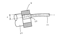
一般に、円筒状ワークの内面研削は、図4に示すように、回転軸21の軸心に対して所定の角度θだけ傾斜させた主軸20に取り付けたワークWの内周に、回転軸21の先端に取り付けた研削砥石22を挿入し、ワークWの内周面に研削砥石22の外周面を相対的に摺接させることにより行っている。
【0003】
しかし、研削砥石22の砥石径が変化すると、切れ味も変化するため、砥石径の変化に拘わらず、同一の研削条件で研削した場合、研削精度は図5に示すように変化する。
【0004】
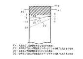
すなわち、砥石径が大きい間は、砥石22の切れ味が悪く、回転軸21の撓みも大きいため、荒研削終了時は点線C1で示すように仕上げ代(端面P1側の仕上げ代8μ)もテーパ量(端面P1側とP2側の内径差21μ)も大きい。したがって、さらに仕上げ研削及びスパークアウトを行った後も、点線C2で示すような切り残しを生じ、テーパ量もそれ程小さくならない。砥石径が小さくなると、砥石22の切れ味が向上し、回転軸21の撓みも小さくなるため、荒研削終了時は一点鎖線D1で示すように仕上げ代もテーパ量も砥石径が大きいときよりも小さくなる。このため、仕上げ研削及びスパークアウト終了時の切り残しとテーパ量はなくなり、良好な研削精度が得られるが、砥石22の切れ味がよい分、研削面の面粗度は砥石径が大きいときよりも悪くなる。
【0005】
従来、このような内面研削では、ワークWの内径寸法及び円筒度を高精度に仕上げるために、次のような加工方法を採用している。すなわち、ワークWの内径寸法を高精度に仕上げるためにゲージ加工を採用し、仕上げ代が一定になるように荒研削から仕上げ研削への切込み速度の切換位置を制御している。なお、ゲージ加工とは、インプロセスゲージで直接ワークWの内周面を測定しながら行う研削方法をいう。さらに、ワークWの内周面の円筒度を高精度に仕上げるために、研削砥石22の切込み速度を砥石径の大小によって変化させている。これは、砥石径が小さくなると、切れ味がよいため、研削加工中の回転軸21の撓みが小さくなり、ワークWの内周面のテーパ量が変化するためである。
【0006】
【発明が解決しようとする課題】
しかしながら、前記インプロセスゲージは高価であるばかりでなく、外力により損傷しやすいため、取り扱いが非常に困難である。また、砥石径の大小により切込み送り速度を変化させる方法では、砥石径が小さくなると、内径テーパ量を砥石径が大きいときと同一にするために切込み送り速度を大きくする必要があるが、砥石22の切れ味がよくなった分、研削面の面粗度が悪くなる。
【0007】
そこで、本発明は、インプロセスゲージを使用しない簡単な構成で、高精度にワークの内周面を研削することのできる内面研削装置を提供することを課題とする。
【0008】
【課題を解決するための手段】
本発明は、前記課題を解決するための手段として、主軸に取り付けたワークの内周面に、回転軸に取り付けた研削砥石の外周面を摺接させることにより、ワークの内周面を研削加工するようにした内面研削装置において、
前記ワークと研削砥石の回転中心のなす角度を調整可能な角度調整手段を設け、
前記研削砥石の砥石径の変化に応じて、前記角度調整手段を駆動してワークと研削砥石の回転中心のなす角度を調整すると共に、荒研削から仕上げ研削への切込み速度の切換位置を変更するようにしたものである。
【0009】
前記研削砥石の砥石径の変化に応じて、研削面の傾きを打ち消すように、前記研削砥石を所定の傾きを有する形状にドレス成形すると共に、荒研削から仕上げ研削への切込み速度の切換位置を変更するようにしてもよい。
【0010】
前記研削砥石の砥石径の変化に応じて、仕上げ研削の切込み完了位置や、仕上げ研削後のスパークアウト時間を変更するのが好ましい。
【0011】
【発明の実施の形態】
以下、本発明の実施形態を添付図面に従って説明する。
【0012】
図1は、本実施形態に係る内面研削装置の概略平面図である。この内面研削装置は、大略、ベッド1上に、主軸台2と砥石台3とを設けたものである。
【0013】
主軸台2は、ベッド1上に固定した主軸下部台4と、この主軸下部台4に載置されてX軸方向(図1中、上下方向)に往復移動する主軸テーブル5と、この主軸テーブル5に載置されて水平面内で旋回可能な主軸部6とからなる。
【0014】
前記主軸テーブル5は、主軸下部台4に設けた切込みサーボモータ7の駆動によりZ軸方向の所定位置に位置決めされるようになっている。前記主軸部6は、主軸テーブル5に支軸8を中心として回動自在に設けられている。主軸部6の回動位置は、主軸スイベル用サーボモータ9の駆動により調整可能となっている。主軸部6には、チャック10が取り付けられ、そこには円筒状のワークWが保持されている。そして、図示しないモータを駆動すると、主軸部6がチャック10を介してワークWと共に回転するようになっている。
【0015】
砥石台3は、砥石台本体11と、この砥石台本体11上をZ軸方向(図1中、左右方向)に往復移動可能に設けた砥石テーブル12と、この砥石テーブル12に固定したホイールヘッド13とからなる。
【0016】
前記砥石テーブル12は、テーブル駆動サーボモータ14の駆動により、砥石台本体11上をZ軸方向の所定位置に位置決めされるようになっている。前記ホイールヘッド13から延びる回転軸15の先端には研削砥石16が固定されている。そして、ホイールヘッド13に内蔵する図示しないモータを駆動すると、回転軸15を介して研削砥石16が回転し、ワークWの内周面を研削できるようになっている。
【0017】
前記切込みサーボモータ7、主軸スイベル用サーボモータ9、テーブル駆動サーボモータ14等は、制御装置17からの入力信号に基づいて駆動制御されるようになっている。
【0018】
次に、前記内面研削装置による内面研削加工について説明する。
【0019】
なお、本実施形態での内面研削加工は、荒研削、仕上げ研削及びスパークアウトの各工程により行っている。また、前記研削砥石16の切込み送り速度は一定値としている。研削加工中、回転軸15は撓むため、ワークWの内径は切込み送り量と同じだけ大きくならず、切り残しが生じるが、研削砥石16の切れ味は砥石径の大小により変化するので、この切り残し量も変化する。インプロセスゲージを使用しないサイズ加工においても、実質的な仕上げ研削量をできるだけ一定にし、ワークWの内周面の円筒度及び面粗度を安定させる目的で、切込み送り位置は、研削砥石16の外径寸法の違いに応じて異ならせている。
【0020】
荒研削では、切込み送り位置を研削砥石16の外径寸法の変化に応じて変更する。すなわち、研削砥石16は、外径寸法が大きければ大きい程、ワークWの研削面に対する食い込み角度が小さくて切れ味が悪い。このため、切込み送り位置(荒研削寸法A1)は、図2中、1点鎖線a1で示すように、研削砥石16の外径寸法が大きい間は大きくとり、切込み速度の切換時期を変更し、実質的な仕上げ研削量を一定にするようにしている。これにより、外径寸法が大きくて切れ味の悪い研削砥石16であっても、ワークWの内周面のテーパ量が大きくならないようにすることが可能となる。
【0021】
その後、所定数のワークを研削し、研削砥石16の表面が荒れて加工精度が悪くなると、ドレス成形により砥石表面を正常にする。そして、ドレス成形により研削砥石16の外径寸法は徐々に小さくなってくるが、それにつれて研削砥石16のワークWの研削面に対する食い込み角度が大きくなって切れ味が良くなるので、図2中、実線b1で示すように、荒研削での切込み送り寸法(荒研削寸法B1)が小さくなるように制御する。但し、この切込み送り寸法B1は、研削砥石16の径寸法に応じて、複数段階で制御するようにしてもよいし、無段階で制御するようにしてもよい。
【0022】
仕上げ研削でも、前記荒研削のときと同様に、切込み送り位置を研削砥石16の外径寸法の変化に応じて変更する。前記切込み送り位置(仕上げ研削寸法A2)は、図2中、1点鎖線a2で示すように、研削砥石16の外径寸法が大きい間は大きくとり、外径寸法が小さくなるにつれて、図2中、実線b2で示すように、小さく抑制する。
【0023】
スパークアウトでは、ワークWに対する研削砥石16の切込み送りを終了し、そのままの状態でワークW及び研削砥石16の回転を続行する。この場合、スパークアウト時間は、研削砥石16の径寸法に応じて変更する。すなわち、研削砥石16の外径寸法が大きい間は短いスパークアウト時間Tsとし、外径寸法が小さくなるに従って長いスパークアウト時間Tlとする。これは、研削砥石16の外径寸法が大きい間は、ワークWに対する食い込み角度が小さく、所望の面粗度が得られるが、外径寸法が小さくなると、研削砥石16の切れ味が良くなり、面粗度が悪化することが想定されるからである。
【0024】
前記研削方法により研削されたワークWの研削精度は図3に示すようになる。すなわち、前記研削方法では、荒研削及び仕上げ研削の切込み送り位置を砥石径の変化に応じて変更しているので、図5と比較しても明らかなように、砥石径の大きい研削砥石16の場合の荒研削及び仕上げ研削終了時の切り残し量が小さくなっている。
【0025】
しかし、前記研削方法によっても、砥石径が大きい場合の仕上げ研削及びスパークアウト終了時のテーパ量は改善されていない。そこで、本実施形態の研削方法では、さらに砥石径の変化に応じて回転軸15の軸心に対する主軸部6の傾斜角も変更する。すなわち、図3に示すワークWの場合であれば、砥石径が大きい場合の回転軸15の軸心に対する主軸部6の傾斜角を研削砥石16の外径が小さい場合の傾斜角よりもαだけ大きくする。この傾斜角の変更も、荒研削時の切込み送り位置の変更と同様に、研削砥石16の径寸法に応じて複数段階で制御するようにしてもよいし、無段階で制御するようにしてもよい。
【0026】
このように、前記実施形態では、ワークWの切込み速度を従来のように砥石径に応じて変化させることなく一定にしても、所望の面粗度を得ることができると共に、内径の仕上げ寸法をほぼ一定に揃え、研削面の傾きをもなくすことが可能である。
【0027】
なお、前記実施形態では、主軸部6の回動位置を調整することにより、ワークWの研削面の傾きを修正するようにしたが、研削砥石16の外周形状自体に傾きを持たせることにより修正するようにしても構わない。すなわち、研削砥石16を、先端側に向かうに従って徐々に断面積が大きくなるようにドレス成形する。この場合、研削砥石16の外径寸法が大きければ、前述の研削結果に基づいてドレス成形時の傾きを大きく取り、外径寸法が小さくなれば、小さくすることは勿論である。
【0028】
【発明の効果】
以上の説明から明らかなように、本発明に係る内面研削装置によれば、ワークと研削砥石の回転中心のなす角度を調整するようにしたり、研削砥石を所定の傾きを有するようにドレス成形するようにしたので、研削加工時の回転軸の撓みを考慮して傾きのない適切な研削面を得ることができる。
【0029】
また、研削砥石の砥石径に応じて、荒研削から仕上げ研削への切込み速度の切換時期や、仕上げ研削の切込み完了位置や、仕上げ研削後のスパークアウト位置を変更するようにしたので、所望の面粗度に研削し、かつ、無駄な時間を削減して効率的な研削作業を実現できる。
【図面の簡単な説明】
【図1】 本実施形態に係る内面研削装置の概略平面図である。
【図2】 研削時間と切込み寸法との関係を示すグラフである。
【図3】 本実施形態の研削方法で研削されたワークの内径形状を示す部分断面図である。
【図4】 従来例に係る内面研削装置の部分断面図である。
【図5】 従来の研削方法で研削されたワークの内径形状を示す部分断面図である。
【符号の説明】
2: 主軸台
3: 砥石台
6: 主軸部
9: 主軸スイベル用サーボモータ
14: テーブル駆動サーボモータ
15: 回転軸
16: 研削砥石
17: 制御装置[0001]
BACKGROUND OF THE INVENTION
The present invention relates to an internal grinding device for grinding an inner peripheral surface of a workpiece.
[0002]
[Prior art]
In general, as shown in FIG. 4, internal grinding of a cylindrical workpiece is performed on the inner periphery of the workpiece W attached to the
[0003]
However, if the grinding wheel diameter of the grinding
[0004]
That is, while the grindstone diameter is large, the sharpness of the
[0005]
Conventionally, in such internal grinding, in order to finish the inner diameter dimension and cylindricity of the workpiece W with high accuracy, the following processing method is employed. That is, in order to finish the inner diameter dimension of the workpiece W with high accuracy, gauge processing is adopted, and the switching position of the cutting speed from rough grinding to finish grinding is controlled so that the finishing allowance is constant. The gauge processing refers to a grinding method that is performed while directly measuring the inner peripheral surface of the workpiece W with an in-process gauge. Furthermore, in order to finish the cylindricity of the inner peripheral surface of the workpiece W with high accuracy, the cutting speed of the
[0006]
[Problems to be solved by the invention]
However, the in-process gauge is not only expensive, but also easily damaged by external force, so that it is very difficult to handle. Further, in the method of changing the cutting feed speed depending on the size of the grindstone, when the grindstone diameter is small, it is necessary to increase the cutting feed speed in order to make the inner diameter taper amount the same as when the grindstone diameter is large. The surface roughness of the ground surface deteriorates due to the improved sharpness.
[0007]
Therefore, an object of the present invention is to provide an inner surface grinding apparatus capable of grinding an inner peripheral surface of a workpiece with high accuracy with a simple configuration that does not use an in-process gauge.
[0008]
[Means for Solving the Problems]
As a means for solving the above-mentioned problems, the present invention provides a method for grinding the inner peripheral surface of a workpiece by sliding the outer peripheral surface of a grinding wheel attached to a rotary shaft to the inner peripheral surface of a workpiece attached to a main shaft. In the internal grinding device designed to
Provided with an angle adjusting means capable of adjusting an angle formed by the rotation center of the workpiece and the grinding wheel,
In accordance with the change in the grinding wheel diameter, the angle adjusting means is driven to adjust the angle formed between the rotation center of the workpiece and the grinding wheel, and the cutting speed switching position from rough grinding to finish grinding is changed. It is what I did.
[0009]
The grinding wheel is dressed into a shape having a predetermined inclination so as to cancel the inclination of the grinding surface according to the change in the grinding wheel diameter of the grinding wheel, and the cutting speed switching position from rough grinding to finish grinding is set. It may be changed.
[0010]
It is preferable to change the cutting completion position of finish grinding and the spark-out time after finish grinding according to the change in the grinding wheel diameter of the grinding wheel.
[0011]
DETAILED DESCRIPTION OF THE INVENTION
Hereinafter, embodiments of the present invention will be described with reference to the accompanying drawings.
[0012]
FIG. 1 is a schematic plan view of an internal grinding device according to the present embodiment. This internal grinding apparatus generally has a
[0013]
The
[0014]
The spindle table 5 is positioned at a predetermined position in the Z-axis direction by driving a
[0015]
The
[0016]
The grindstone table 12 is positioned on the grindstone base body 11 at a predetermined position in the Z-axis direction by driving a table
[0017]
The cutting
[0018]
Next, the internal grinding process by the internal grinding apparatus will be described.
[0019]
In addition, the internal grinding process in this embodiment is performed by each process of rough grinding, finish grinding, and spark out. The cutting feed speed of the grinding wheel 16 is a constant value. Since the rotating
[0020]
In rough grinding, the cutting feed position is changed according to the change in the outer diameter of the grinding wheel 16. That is, the larger the outer diameter dimension of the grinding wheel 16, the smaller the biting angle with respect to the grinding surface of the workpiece W and the worse the sharpness. For this reason, the cutting feed position (rough grinding dimension A1) is large as long as the outer diameter dimension of the grinding wheel 16 is large, as shown by a one-dot chain line a1 in FIG. The substantial finish grinding amount is made constant. As a result, even if the grinding wheel 16 has a large outer diameter and poor sharpness, the taper amount of the inner peripheral surface of the workpiece W can be prevented from increasing.
[0021]
Thereafter, a predetermined number of workpieces are ground, and when the surface of the grinding wheel 16 becomes rough and processing accuracy deteriorates, the surface of the grinding wheel is made normal by dressing. The outer diameter of the grinding wheel 16 gradually decreases as a result of dressing, but the biting angle of the grinding wheel 16 with respect to the grinding surface of the workpiece W increases and the sharpness is improved. As shown by b1, the cutting feed dimension (rough grinding dimension B1) in rough grinding is controlled to be small. However, the cutting feed dimension B1 may be controlled in a plurality of steps according to the diameter of the grinding wheel 16, or may be controlled in a stepless manner.
[0022]
Even in the finish grinding, the cutting feed position is changed according to the change in the outer diameter of the grinding wheel 16 as in the rough grinding. As shown by a one-dot chain line a2 in FIG. 2, the cutting feed position (finish grinding dimension A2) is increased while the outer diameter dimension of the grinding wheel 16 is large, and in FIG. As shown by the solid line b2, it is suppressed to be small.
[0023]
In the spark-out, the cutting feed of the grinding wheel 16 to the workpiece W is finished, and the rotation of the workpiece W and the grinding wheel 16 is continued as it is. In this case, the spark-out time is changed according to the diameter of the grinding wheel 16. That is, while the outer diameter dimension of the grinding wheel 16 is large, the short spark-out time Ts is set, and as the outer diameter dimension becomes smaller, the longer spark-out time Tl is set. While the grinding wheel 16 has a large outer diameter, the biting angle with respect to the workpiece W is small and a desired surface roughness can be obtained. However, when the outer diameter is small, the grinding wheel 16 is sharpened and the surface is improved. This is because the roughness is assumed to deteriorate.
[0024]
The grinding accuracy of the workpiece W ground by the grinding method is as shown in FIG. That is, in the grinding method, since the cutting feed positions for rough grinding and finish grinding are changed according to the change in the grinding wheel diameter, as is apparent from comparison with FIG. In this case, the amount of uncut residue at the end of rough grinding and finish grinding is small.
[0025]
However, even with the grinding method, the taper amount at the end of finish grinding and spark-out when the grindstone diameter is large is not improved. Therefore, in the grinding method of this embodiment, the inclination angle of the
[0026]
As described above, in the above-described embodiment, a desired surface roughness can be obtained even when the cutting speed of the workpiece W is constant without changing according to the grindstone diameter as in the past, and the finished dimension of the inner diameter is set. It is possible to eliminate the inclination of the grinding surface by making the surfaces almost constant.
[0027]
In the above-described embodiment, the inclination of the grinding surface of the workpiece W is corrected by adjusting the rotation position of the
[0028]
【The invention's effect】
As is clear from the above description, according to the internal grinding device of the present invention, the angle formed by the rotation center of the workpiece and the grinding wheel is adjusted, or the grinding wheel is dressed so as to have a predetermined inclination. Since it did in this way, the appropriate grinding surface without an inclination can be obtained in consideration of the bending of the rotating shaft at the time of grinding.
[0029]
In addition, the timing of switching the cutting speed from rough grinding to finish grinding, the finish completion position of finish grinding, and the spark-out position after finish grinding are changed according to the grinding wheel diameter. Efficient grinding work can be realized by grinding to the surface roughness and reducing wasted time.
[Brief description of the drawings]
FIG. 1 is a schematic plan view of an internal grinding device according to the present embodiment.
FIG. 2 is a graph showing the relationship between grinding time and depth of cut.
FIG. 3 is a partial cross-sectional view showing an inner diameter shape of a workpiece ground by the grinding method of the present embodiment.
FIG. 4 is a partial cross-sectional view of an internal grinding device according to a conventional example.
FIG. 5 is a partial sectional view showing an inner diameter shape of a workpiece ground by a conventional grinding method.
[Explanation of symbols]
2: Spindle base 3: Grinding wheel base 6: Spindle part 9: Servo motor for spindle swivel 14: Table drive servo motor 15: Rotating shaft 16: Grinding wheel 17: Controller
Claims (4)
前記ワークと研削砥石の回転中心のなす角度を調整可能な角度調整手段を設け、
前記研削砥石の砥石径の変化に応じて、前記角度調整手段を駆動してワークと研削砥石の回転中心のなす角度を調整すると共に、荒研削から仕上げ研削への切込み速度の切換位置を変更するようにしたことを特徴とする内面研削装置。In the inner surface grinding device that grinds the inner peripheral surface of the workpiece by bringing the outer peripheral surface of the grinding wheel attached to the rotating shaft into sliding contact with the inner peripheral surface of the workpiece attached to the main shaft,
An angle adjusting means capable of adjusting an angle formed by the rotation center of the workpiece and the grinding wheel is provided,
In accordance with the change in the grinding wheel diameter, the angle adjusting means is driven to adjust the angle formed by the rotation center of the workpiece and the grinding wheel, and the cutting speed switching position from rough grinding to finish grinding is changed. An internal grinding device characterized by being configured as described above.
前記研削砥石の砥石径の変化に応じて、研削面の傾きを打ち消すように、前記研削砥石を所定の傾きを有する形状にドレス成形すると共に、荒研削から仕上げ研削への切込み速度の切換位置を変更するようにしたことを特徴とする内面研削装置。In the inner surface grinding device that grinds the inner peripheral surface of the workpiece by bringing the outer peripheral surface of the grinding wheel attached to the rotating shaft into sliding contact with the inner peripheral surface of the workpiece attached to the main shaft,
The grinding wheel is dressed into a shape having a predetermined inclination so as to cancel the inclination of the grinding surface according to the change in the grinding wheel diameter of the grinding wheel, and the cutting speed switching position from rough grinding to finish grinding is set. An internal grinding apparatus characterized by being changed.
Priority Applications (1)
| Application Number | Priority Date | Filing Date | Title |
|---|---|---|---|
| JP05191898A JP3848779B2 (en) | 1998-03-04 | 1998-03-04 | Internal grinding machine |
Applications Claiming Priority (1)
| Application Number | Priority Date | Filing Date | Title |
|---|---|---|---|
| JP05191898A JP3848779B2 (en) | 1998-03-04 | 1998-03-04 | Internal grinding machine |
Publications (2)
| Publication Number | Publication Date |
|---|---|
| JPH11254277A JPH11254277A (en) | 1999-09-21 |
| JP3848779B2 true JP3848779B2 (en) | 2006-11-22 |
Family
ID=12900266
Family Applications (1)
| Application Number | Title | Priority Date | Filing Date |
|---|---|---|---|
| JP05191898A Expired - Fee Related JP3848779B2 (en) | 1998-03-04 | 1998-03-04 | Internal grinding machine |
Country Status (1)
| Country | Link |
|---|---|
| JP (1) | JP3848779B2 (en) |
Cited By (1)
| Publication number | Priority date | Publication date | Assignee | Title |
|---|---|---|---|---|
| CN104493649A (en) * | 2014-12-19 | 2015-04-08 | 无锡大龙马数控机床制造有限责任公司 | Grinding unit of high-speed internal grinder |
Families Citing this family (7)
| Publication number | Priority date | Publication date | Assignee | Title |
|---|---|---|---|---|
| CN102909634B (en) * | 2011-08-04 | 2015-04-22 | 中国有色(沈阳)冶金机械有限公司 | Movable type horizontal lathe grinding diaphragm chamber mechanism |
| JP5852545B2 (en) * | 2012-10-16 | 2016-02-03 | 株式会社岡本工作機械製作所 | Double-head internal grinding machine |
| CN104440425B (en) * | 2014-12-19 | 2016-11-09 | 无锡大龙马数控机床制造有限责任公司 | High-speed capillary electrophoresis |
| CN107081644B (en) * | 2017-05-16 | 2019-05-21 | 新昌县恒盛机械有限公司 | A kind of pipe fitting inner wall grinding device |
| CN109202681B (en) * | 2018-09-18 | 2020-10-27 | 浙江隆达不锈钢有限公司 | Nonrust steel pipe hole polishing equipment |
| CN109909820B (en) * | 2019-03-19 | 2023-10-27 | 湖州师范学院 | Multi-stage treatment device and method for inner surface of cylindrical shell |
| KR102351661B1 (en) * | 2021-05-31 | 2022-01-17 | 피티케이(주) | A device for buffing caps and pipes during the synthesis gasification process of petroleum coke for hydrogen production |
-
1998
- 1998-03-04 JP JP05191898A patent/JP3848779B2/en not_active Expired - Fee Related
Cited By (1)
| Publication number | Priority date | Publication date | Assignee | Title |
|---|---|---|---|---|
| CN104493649A (en) * | 2014-12-19 | 2015-04-08 | 无锡大龙马数控机床制造有限责任公司 | Grinding unit of high-speed internal grinder |
Also Published As
| Publication number | Publication date |
|---|---|
| JPH11254277A (en) | 1999-09-21 |
Similar Documents
| Publication | Publication Date | Title |
|---|---|---|
| JP5034951B2 (en) | Wheel correction device | |
| EP1839809B1 (en) | Grinding method and grinding machine | |
| JP3848779B2 (en) | Internal grinding machine | |
| JP5239251B2 (en) | Traverse grinding apparatus and processing method | |
| JP2007054896A (en) | Grinding method and grinder | |
| JPH06246601A (en) | Grinding method | |
| JP3071640B2 (en) | Deep hole inner surface grinding method for workpieces | |
| JP3212813B2 (en) | Internal grinding machine and its grinding method | |
| JP2003291069A (en) | Grinding wheel for grinder and grinding method using grinding wheel | |
| JPH10128647A (en) | Deburring method and deburring structure of grinding wheel used in the deburring method | |
| JPH10156720A (en) | Method and device for correcting grinding wheel | |
| JP2013240871A (en) | Method of dressing rotary grinding wheel, rotary grinding wheel, and grinding method | |
| JP3049154B2 (en) | Tapered cup grindstone and grinding method for irregularly shaped work using this grindstone | |
| JP2002144199A (en) | Surface grinding method and surface grinding machine for sheet disc-like workpiece | |
| JP2004202656A (en) | Truing method of polisher for polishing | |
| JPH05162005A (en) | Turning machine with cutting tool forming function | |
| JPS62193756A (en) | Grinding machine | |
| JPH0899257A (en) | Grinding device | |
| JP2000176834A (en) | Correction method of grinding wheel, correction device and grinder furnished with it | |
| JPH09174398A (en) | Grinding device and grinding wheel | |
| JPH06312354A (en) | Centerless grinder | |
| JP3322127B2 (en) | Vertical NC grinder | |
| JPH04300150A (en) | Honing process method of drill | |
| JP2881176B2 (en) | How to fix cup whetstone | |
| JPS61152356A (en) | Grinding method for cylindrical or conical surface |
Legal Events
| Date | Code | Title | Description |
|---|---|---|---|
| A621 | Written request for application examination |
Free format text: JAPANESE INTERMEDIATE CODE: A621 Effective date: 20040914 |
|
| TRDD | Decision of grant or rejection written | ||
| A01 | Written decision to grant a patent or to grant a registration (utility model) |
Free format text: JAPANESE INTERMEDIATE CODE: A01 Effective date: 20060815 |
|
| A61 | First payment of annual fees (during grant procedure) |
Free format text: JAPANESE INTERMEDIATE CODE: A61 Effective date: 20060828 |
|
| R150 | Certificate of patent or registration of utility model |
Free format text: JAPANESE INTERMEDIATE CODE: R150 |
|
| FPAY | Renewal fee payment (event date is renewal date of database) |
Free format text: PAYMENT UNTIL: 20100901 Year of fee payment: 4 |
|
| FPAY | Renewal fee payment (event date is renewal date of database) |
Free format text: PAYMENT UNTIL: 20110901 Year of fee payment: 5 |
|
| FPAY | Renewal fee payment (event date is renewal date of database) |
Free format text: PAYMENT UNTIL: 20110901 Year of fee payment: 5 |
|
| FPAY | Renewal fee payment (event date is renewal date of database) |
Free format text: PAYMENT UNTIL: 20120901 Year of fee payment: 6 |
|
| FPAY | Renewal fee payment (event date is renewal date of database) |
Free format text: PAYMENT UNTIL: 20120901 Year of fee payment: 6 |
|
| FPAY | Renewal fee payment (event date is renewal date of database) |
Free format text: PAYMENT UNTIL: 20130901 Year of fee payment: 7 |
|
| LAPS | Cancellation because of no payment of annual fees |