JP3848389B2 - Equipment for cutting elastomeric material - Google Patents
Equipment for cutting elastomeric material Download PDFInfo
- Publication number
- JP3848389B2 JP3848389B2 JP22203895A JP22203895A JP3848389B2 JP 3848389 B2 JP3848389 B2 JP 3848389B2 JP 22203895 A JP22203895 A JP 22203895A JP 22203895 A JP22203895 A JP 22203895A JP 3848389 B2 JP3848389 B2 JP 3848389B2
- Authority
- JP
- Japan
- Prior art keywords
- cutting
- wire
- elastomeric material
- collet
- elongated body
- Prior art date
- Legal status (The legal status is an assumption and is not a legal conclusion. Google has not performed a legal analysis and makes no representation as to the accuracy of the status listed.)
- Expired - Fee Related
Links
Images


Classifications
-
- B—PERFORMING OPERATIONS; TRANSPORTING
- B26—HAND CUTTING TOOLS; CUTTING; SEVERING
- B26B—HAND-HELD CUTTING TOOLS NOT OTHERWISE PROVIDED FOR
- B26B27/00—Hand cutting tools not provided for in the preceding groups, e.g. finger rings for cutting string, devices for cutting by means of wires
-
- B—PERFORMING OPERATIONS; TRANSPORTING
- B23—MACHINE TOOLS; METAL-WORKING NOT OTHERWISE PROVIDED FOR
- B23D—PLANING; SLOTTING; SHEARING; BROACHING; SAWING; FILING; SCRAPING; LIKE OPERATIONS FOR WORKING METAL BY REMOVING MATERIAL, NOT OTHERWISE PROVIDED FOR
- B23D57/00—Sawing machines or sawing devices not covered by one of the preceding groups B23D45/00 - B23D55/00
- B23D57/003—Sawing machines or sawing devices working with saw wires, characterised only by constructional features of particular parts
- B23D57/0046—Sawing machines or sawing devices working with saw wires, characterised only by constructional features of particular parts of devices for feeding, conveying or clamping work
-
- B—PERFORMING OPERATIONS; TRANSPORTING
- B23—MACHINE TOOLS; METAL-WORKING NOT OTHERWISE PROVIDED FOR
- B23D—PLANING; SLOTTING; SHEARING; BROACHING; SAWING; FILING; SCRAPING; LIKE OPERATIONS FOR WORKING METAL BY REMOVING MATERIAL, NOT OTHERWISE PROVIDED FOR
- B23D57/00—Sawing machines or sawing devices not covered by one of the preceding groups B23D45/00 - B23D55/00
- B23D57/0007—Sawing machines or sawing devices not covered by one of the preceding groups B23D45/00 - B23D55/00 using saw wires
-
- B—PERFORMING OPERATIONS; TRANSPORTING
- B26—HAND CUTTING TOOLS; CUTTING; SEVERING
- B26D—CUTTING; DETAILS COMMON TO MACHINES FOR PERFORATING, PUNCHING, CUTTING-OUT, STAMPING-OUT OR SEVERING
- B26D1/00—Cutting through work characterised by the nature or movement of the cutting member or particular materials not otherwise provided for; Apparatus or machines therefor; Cutting members therefor
- B26D1/01—Cutting through work characterised by the nature or movement of the cutting member or particular materials not otherwise provided for; Apparatus or machines therefor; Cutting members therefor involving a cutting member which does not travel with the work
- B26D1/547—Cutting through work characterised by the nature or movement of the cutting member or particular materials not otherwise provided for; Apparatus or machines therefor; Cutting members therefor involving a cutting member which does not travel with the work having a wire-like cutting member
-
- B—PERFORMING OPERATIONS; TRANSPORTING
- B26—HAND CUTTING TOOLS; CUTTING; SEVERING
- B26D—CUTTING; DETAILS COMMON TO MACHINES FOR PERFORATING, PUNCHING, CUTTING-OUT, STAMPING-OUT OR SEVERING
- B26D7/00—Details of apparatus for cutting, cutting-out, stamping-out, punching, perforating, or severing by means other than cutting
- B26D7/08—Means for treating work or cutting member to facilitate cutting
- B26D7/084—Means for treating work or cutting member to facilitate cutting specially adapted for cutting articles composed of at least two different materials, e.g. using cutters of different shapes
-
- B—PERFORMING OPERATIONS; TRANSPORTING
- B29—WORKING OF PLASTICS; WORKING OF SUBSTANCES IN A PLASTIC STATE IN GENERAL
- B29C—SHAPING OR JOINING OF PLASTICS; SHAPING OF MATERIAL IN A PLASTIC STATE, NOT OTHERWISE PROVIDED FOR; AFTER-TREATMENT OF THE SHAPED PRODUCTS, e.g. REPAIRING
- B29C2793/00—Shaping techniques involving a cutting or machining operation
- B29C2793/0081—Shaping techniques involving a cutting or machining operation before shaping
-
- B—PERFORMING OPERATIONS; TRANSPORTING
- B29—WORKING OF PLASTICS; WORKING OF SUBSTANCES IN A PLASTIC STATE IN GENERAL
- B29K—INDEXING SCHEME ASSOCIATED WITH SUBCLASSES B29B, B29C OR B29D, RELATING TO MOULDING MATERIALS OR TO MATERIALS FOR MOULDS, REINFORCEMENTS, FILLERS OR PREFORMED PARTS, e.g. INSERTS
- B29K2021/00—Use of unspecified rubbers as moulding material
-
- B—PERFORMING OPERATIONS; TRANSPORTING
- B29—WORKING OF PLASTICS; WORKING OF SUBSTANCES IN A PLASTIC STATE IN GENERAL
- B29L—INDEXING SCHEME ASSOCIATED WITH SUBCLASS B29C, RELATING TO PARTICULAR ARTICLES
- B29L2030/00—Pneumatic or solid tyres or parts thereof
- B29L2030/002—Treads
-
- Y—GENERAL TAGGING OF NEW TECHNOLOGICAL DEVELOPMENTS; GENERAL TAGGING OF CROSS-SECTIONAL TECHNOLOGIES SPANNING OVER SEVERAL SECTIONS OF THE IPC; TECHNICAL SUBJECTS COVERED BY FORMER USPC CROSS-REFERENCE ART COLLECTIONS [XRACs] AND DIGESTS
- Y10—TECHNICAL SUBJECTS COVERED BY FORMER USPC
- Y10T—TECHNICAL SUBJECTS COVERED BY FORMER US CLASSIFICATION
- Y10T83/00—Cutting
- Y10T83/687—By tool reciprocable along elongated edge
- Y10T83/6905—With tool in-feed
- Y10T83/693—Of rectilinearly reciprocating tool
-
- Y—GENERAL TAGGING OF NEW TECHNOLOGICAL DEVELOPMENTS; GENERAL TAGGING OF CROSS-SECTIONAL TECHNOLOGIES SPANNING OVER SEVERAL SECTIONS OF THE IPC; TECHNICAL SUBJECTS COVERED BY FORMER USPC CROSS-REFERENCE ART COLLECTIONS [XRACs] AND DIGESTS
- Y10—TECHNICAL SUBJECTS COVERED BY FORMER USPC
- Y10T—TECHNICAL SUBJECTS COVERED BY FORMER US CLASSIFICATION
- Y10T83/00—Cutting
- Y10T83/687—By tool reciprocable along elongated edge
- Y10T83/6905—With tool in-feed
- Y10T83/6945—With passive means to guide tool directly
- Y10T83/695—By plural opposed guide surfaces
- Y10T83/696—With relative adjustment between guide and work or work-support
- Y10T83/6965—By or with additional movable work-support portion
-
- Y—GENERAL TAGGING OF NEW TECHNOLOGICAL DEVELOPMENTS; GENERAL TAGGING OF CROSS-SECTIONAL TECHNOLOGIES SPANNING OVER SEVERAL SECTIONS OF THE IPC; TECHNICAL SUBJECTS COVERED BY FORMER USPC CROSS-REFERENCE ART COLLECTIONS [XRACs] AND DIGESTS
- Y10—TECHNICAL SUBJECTS COVERED BY FORMER USPC
- Y10T—TECHNICAL SUBJECTS COVERED BY FORMER US CLASSIFICATION
- Y10T83/00—Cutting
- Y10T83/687—By tool reciprocable along elongated edge
- Y10T83/705—With means to support tool at opposite ends
- Y10T83/7055—And apply drive force to both ends of tool
- Y10T83/7065—By reciprocating rigid support
-
- Y—GENERAL TAGGING OF NEW TECHNOLOGICAL DEVELOPMENTS; GENERAL TAGGING OF CROSS-SECTIONAL TECHNOLOGIES SPANNING OVER SEVERAL SECTIONS OF THE IPC; TECHNICAL SUBJECTS COVERED BY FORMER USPC CROSS-REFERENCE ART COLLECTIONS [XRACs] AND DIGESTS
- Y10—TECHNICAL SUBJECTS COVERED BY FORMER USPC
- Y10T—TECHNICAL SUBJECTS COVERED BY FORMER US CLASSIFICATION
- Y10T83/00—Cutting
- Y10T83/748—With work immobilizer
- Y10T83/7487—Means to clamp work
- Y10T83/754—Clamp driven by yieldable means
-
- Y—GENERAL TAGGING OF NEW TECHNOLOGICAL DEVELOPMENTS; GENERAL TAGGING OF CROSS-SECTIONAL TECHNOLOGIES SPANNING OVER SEVERAL SECTIONS OF THE IPC; TECHNICAL SUBJECTS COVERED BY FORMER USPC CROSS-REFERENCE ART COLLECTIONS [XRACs] AND DIGESTS
- Y10—TECHNICAL SUBJECTS COVERED BY FORMER USPC
- Y10T—TECHNICAL SUBJECTS COVERED BY FORMER US CLASSIFICATION
- Y10T83/00—Cutting
- Y10T83/748—With work immobilizer
- Y10T83/7487—Means to clamp work
- Y10T83/7547—Liquid pressure actuating means
-
- Y—GENERAL TAGGING OF NEW TECHNOLOGICAL DEVELOPMENTS; GENERAL TAGGING OF CROSS-SECTIONAL TECHNOLOGIES SPANNING OVER SEVERAL SECTIONS OF THE IPC; TECHNICAL SUBJECTS COVERED BY FORMER USPC CROSS-REFERENCE ART COLLECTIONS [XRACs] AND DIGESTS
- Y10—TECHNICAL SUBJECTS COVERED BY FORMER USPC
- Y10T—TECHNICAL SUBJECTS COVERED BY FORMER US CLASSIFICATION
- Y10T83/00—Cutting
- Y10T83/869—Means to drive or to guide tool
- Y10T83/8874—Uniplanar compound motion
- Y10T83/8876—Reciprocating plus work approach [e.g., saw type]
-
- Y—GENERAL TAGGING OF NEW TECHNOLOGICAL DEVELOPMENTS; GENERAL TAGGING OF CROSS-SECTIONAL TECHNOLOGIES SPANNING OVER SEVERAL SECTIONS OF THE IPC; TECHNICAL SUBJECTS COVERED BY FORMER USPC CROSS-REFERENCE ART COLLECTIONS [XRACs] AND DIGESTS
- Y10—TECHNICAL SUBJECTS COVERED BY FORMER USPC
- Y10T—TECHNICAL SUBJECTS COVERED BY FORMER US CLASSIFICATION
- Y10T83/00—Cutting
- Y10T83/929—Tool or tool with support
- Y10T83/9292—Wire tool
-
- Y—GENERAL TAGGING OF NEW TECHNOLOGICAL DEVELOPMENTS; GENERAL TAGGING OF CROSS-SECTIONAL TECHNOLOGIES SPANNING OVER SEVERAL SECTIONS OF THE IPC; TECHNICAL SUBJECTS COVERED BY FORMER USPC CROSS-REFERENCE ART COLLECTIONS [XRACs] AND DIGESTS
- Y10—TECHNICAL SUBJECTS COVERED BY FORMER USPC
- Y10T—TECHNICAL SUBJECTS COVERED BY FORMER US CLASSIFICATION
- Y10T83/00—Cutting
- Y10T83/929—Tool or tool with support
- Y10T83/9457—Joint or connection
- Y10T83/9473—For rectilinearly reciprocating tool
Abstract
Description
【0001】
【発明の属する技術分野】
本発明は、エラストマー材料を切断する方法及び装置、特に補強本体と後に共に接合される切断端部を有する本体とを有する異なる断面形状のエラストマー材料を切断する装置に関する。
【0002】
【従来の技術】
エラストマー材料を切断する方法及び装置は公知である。これらの従来の切断技術は、切断ホイール、超音波、はさみタイプ及びギロチン型ナイフを有する。
【発明が解決しようとする課題】
ギロチン型ナイフはやや有効であるが、同様に欠点がある。1つの欠点は、ナイフがエラストマー材料を貫通するとき、エラストマー材料の切断面が変形する傾向があることである。これはエラストマー材料の両端を接合することをさらに困難にする。ギロチン型ナイフの第2の欠点は、刃が切れなくなったときに、またはエラストマー材料の小さい部分が刃に堆積し始めると、切断面の品質が劣化することである。第3の欠点は、刃がタイヤトレッドを30°未満の角度で切断することができないことである。最後にギロチン型ナイフは、切断で熱を発生する傾向があり、ナイフの温度が上昇し、ある場合には切断場所で未加硫エラストマーを予備加硫する。これは、適切に接合すべき切断縁の能力を低下させる。
【0003】
本発明のカッタは、変形または予備加硫を起こすことなく30°未満の角度でトレッドを切断することができる。これは精密に迅速に行われる。またカッタは、切断処理の改良及び装置によって切断されたエラストマー材料の接合面及び接合品質に対する改良を行う。
【0004】
【課題を解決するための手段】
本発明によれば、エラストマー材料を切断する新しい改良された装置が提供される。
【0005】
特に、第1及び第2の端部を有するワイヤと、その間にワイヤに張力をかけて固定する第1と第2の固定装置とを具備しているエラストマー材料を切断する装置が提供される。一対のアームは、第1及び第2の固定装置を支持する。このアームはモータ駆動回転軸に取り付けられた偏心器によって駆動されるときに、振動することができるように旋回可能に取り付けられる。横断装置は、ワイヤが振動中にエラストマー材料を通って切断するようにワイヤとエラストマー材料との間に相対運動を形成する。
【0008】
上記目的を達成するために本発明のエラストマー材料を切断する装置は、エラストマー材料の細長い本体を支持すると共に所定の切断位置に開口部を有するコンベヤに沿った所定の切断位置および角度でエラストマー材料の細長い本体を所定の長さに切断する装置であって、開口部を通って移動する切断組立体であって、該切断組立体上に揺動するように取り付けられ、間隔をおいたアーム上に各端部が支持されている切断ワイヤを含み、各アームは該アームを揺動運動させるための揺動取付部と、アームに接続され、各アームを揺動取付部を中心として揺動させて切断ワイヤを往復動させ、エラストマー材料の細長い本体にスリットを形成する駆動手段を含む切断組立体と、所定の切断位置で細長い本体内を通ってスリットを延ばすために細長い本体を横切って切断組立体を相対的に動かす手段とを有する。
【0009】
また、本発明のエラストマー材料を切断する装置は、切断ワイヤの各端部が、切断ワイヤに係合する各アームに取り付けられたコレットによって締付けられており、コレットの各々は、コレットを押して切断ワイヤに締付けにより係合させるナット部材を有するものであってもよい。
【0010】
また、本発明のエラストマー材料を切断する装置は、コレットの各々が、アームの1つに揺動可能に取り付けられているものであってもよい。
【0012】
【実施例】
以下、本発明の一実施例を図面を参照して詳細に説明する。図1は、本発明による切断装置の正面図である。本装置は、切断ワイヤ12を有する切断組立体10を有する。切断ワイヤ12は、高張力のスチールから製造されることが好ましく、第1の端部14と第2の端部16とを有する。このワイヤ12は、断面が円形で0.01インチ(0.0254cm)と0.050インチ(0.129cm)との間の直径を有することが好ましい。この実施例の好ましいワイヤ12は、0.129cmの直径を有する。
【0013】
ワイヤ12の第1と第2の端部14,16は固定装置に固定される。この実施例の好ましい固定装置は、コレット22,24である。図3を参照すると、コレット22の拡大図が示されている。次のコレット22の説明はコレット24にも適用することができる。コレット22は、外側のねじ付き面32を有する第1の内側の円筒形ハウジング28を有する。またコレット22は、第2の外側の円筒形ハウジングまたはつまみナット38を有し、このつまみナット38は、第1のハウジング28の外面のねじに係合するめねじ面40を有する。つまみナット38は、第1のハウジング28に関して回転しワイヤ12の第1の端部14をコレット本体41に固定することができる。
【0014】
ワイヤ12には、均一に負荷が適用される。なぜならば、それは常に第1のアーム42の旋回ピン30の中央を通過し、それによって作動中にワイヤが曲がりまたはたわむ可能性を無くすか著しく小さくする。さらに、旋回ピン30は、切断サイクル中にワイヤ12の曲げ応力を無くす。ワイヤ12は、エラストマー材料の切断中に弓形に変形される。このような弓形は、正規には固定点で曲げ応力を発生するが、これらの曲げ応力は、旋回ピン30によって軽減され、ワイヤ寿命が改良される。このワイヤ12は、コレット22,24を通してねじ込むことができ、ワイヤ交換を容易にする。
【0015】
ワイヤ12がコレット22にねじ込まれると、ワイヤ12をコレット22の中に固定するためにつまみナット34が回転される。つまみナット34の締め付けはワイヤの軸線方向に行われるので、ワイヤ12は、その処理中にねじれず曲がらない。さらに、コレット本体41の内端36は、手で締め付けるつまみナット38で大きな固定力を発生するように小さい角度で傾斜する傾斜面を有する。
【0016】
ばねピン44は、つまみナット38を締め付けるときに、コレット本体の回転を防止する。これは、ワイヤ12がねじれ応力を生じることを防止する。またこのばねピン44は、つまみナット38をゆるめたときに、コレット本体41を保持するように作用する。
【0017】
図3Aを参照すると、コレット本体41が端面図で示されている。コレット本体41の固定部品45は、ワイヤ12のほぼ全周にわたって接触する。この360°にわたる接触は、2つの部品による固定において見られる標準的な2点接触に比して大きな改良点である。
【0018】
図1及び図2を参照すると、第2のコレット24がフレーム52に旋回可能に取り付けられている第2のアーム48に対して旋回可能に取り付けられている。また第1のアーム42は、フレーム52に旋回可能に取り付けられており、中央連結器54によって第2のアーム48に接続されている。
【0019】
図2を参照すると、ワイヤ12は傾斜位置で示されており、すなわち、ワイヤ12は、エラストマー材料を含む平面P1に関して角度WAを形成するか、またはエラストマー材料を含む平面に平行な平面P1に関して平行である。角度WAは10°と80°の間で変化するが、好ましい角度は22.5°である。これは、それらの切断角度において制限を受ける従来技術の切断機構に対する改良である。例えば、ここに示した切断装置10は、未加硫のタイヤを切断するために特に適用可能である。本切断装置で可能な角度の範囲は、タイヤ設計者に対して可能性を広げるものである。
【0020】
図1,2,及び4を連続して参照すると、アーム42及び48は、所定の振動速度でワイヤを振動するように振動される。好ましい実施例において、可変速度モーターの出力軸64に偏心器60が固定される。偏心器60はクランクアーム62によって第1のアーム42に旋回可能に接続されている。可変速度モーター68を調整することができ、それによって軸64が回転され、その結果、振動速度は分速約2,000サイクルまで変えることができる。好ましい実施例において、振動速度は、厚さ、切断するエラストマー部材のタイプ、ワイヤ12の振動速度のようなパラメータに基づいて調整することができる。1つの好ましい組み合わせは、乗用車のタイヤのトレッドを切断するとき、分速1600サイクルの振動速度と秒速2.25インチ(5,72cm)の移動速度である。
【0021】
図1及び図2を連続して参照すると、切断組立体10はワイヤ12と切断すべきエラストマー材料との間に相対運動を形成する横断装置を有する。好ましい実施例において、横断装置は、可変速度モーター78によって駆動されるボールねじ74を有する。フレーム52は、静止支持体88に取り付けられたロッド87に摺動可能に支持されている直線的な軸受82上に取り付けられ、静止支持体88に関してフレームの低摩擦運動を行う。
【0022】
図6を参照すると、切断装置10は、振動ワイヤ12によってエラストマー材料が切断されているとき、エラストマー材料のシートを固定する固定組立体96を有する。エラストマー材料は、図2及び図6に示される平面P1に配置されており、固定組立体96は静止支持体88に取り付けられる。フレーム98はフレーム端部部材104及び106の間に並置される関係に固定された複数のクランプ部材100を有する。部材100は、例えばタイヤトレッドのような切断すべきエラストマー材料の輪郭に適応するように垂直方向に調整可能である。フレーム98は、ガイドロッド105上に取り付けられており、工場の空気のような圧縮空気源に連通する空気ピストンシリンダ組立体110によってエラストマー材料に係合するように、またそれから外れるように垂直方向に可動である。
【0023】
運転において、図10及び図11に示すタイヤトレッド70のようなエラストマー材料の細長い本体をベルトコンベヤの支持体の平面P1に配置し、固定組立体96によって固定する。モーター68は、中央の連結器54によって第2のアーム48に接続されているクランクアーム62によって第1のアームを振動させ、中央連結器54は、第2のアームを振動させ、ワイヤ12を振動させる。次にモーター78は、エラストマー材料のトレッド79に係合したモーター78に隣接した位置から図1に示した左にフレーム52を移動するように作動する。
【0024】
ワイヤ12がトレッド79のエラストマー材料に係合するときに、それは材料にスリット目を形成する。次に、ワイヤ12がトレッド79を通って前進するときに、ワイヤは、均一に前進することができるように材料をわずかな距離だけスリットの前方に進める。接触層のせん断応力の限界に達するまで生じるエラストマー材料のワイヤ12への接触層の付着によって切断が容易にされる。図11に示すように、切断接合面80Aには、振動するワイヤ12が平行な溝81及びリブを表面に形成する処理によって筋が形成される。この表面80Aはタイヤトレッド79の切断端部を接合するためには望ましいものであることが分かっている。事実、部材を横断する切断ワイヤ12を振動させることによってエラストマー材料のタイヤ部材は、切断接合面80A及び80Bの間で接合される。これは、良好な接合のために接着剤を必要としない。トレッド79及び他のタイヤ部品に関しては、切断部分はタイヤ形成機械に環状体を形成するために接合される切断端部を有する。
【0025】
図11に示す重ね継ぎ面80Aは左から右への方向でトレッド79を切断することによって形成される。切断ワイヤ12は、エラストマー材料を移動し、表面をわずかにゆがめる。左から右へ切断される重ね継ぎ面80Aは、同じ大きさだけゆがめられることが分かっている。従って、重ね継ぎ面80A及び80Bは、接合したときに合致し、一致した係合が行われる。
【0026】
図8及び図9を参照すると、エラストマー材料の2つの部材121A及び121Bを同時に切断することができるように1つのベース120に2つの切断組立体10A,10Bを取り付ける本発明の他の実施例を示す。2つの切断組立体10A,10Bは、図1乃至図5の実施例に関して前述した部品と同様な部品を有する。
【0027】
例えば、切断ワイヤ12A及び12Bは、フレーム52Aに旋回可能に取り付けられる振動アーム42A,42B及び48A及び48Bに取り付けられている。アーム42A及び48Aは、中央連結器54Aによって接続されており、アーム42B及び48Bは、中央連結器54Bによって接続されている。可変速度モーター68Aがボールねじに取り付けられた直線軸受124に摺動可能に取り付けられているフレームに取り付けられており、ボールねじは、可変速度モーター126Aによって駆動され、可変速度モーター126Aは、フレーム及び切断ワイヤ12A及び12Bが切断位置130A及び130Bでタイヤ切断係合するように上下に運動可能なように静止支持体88Aに取り付けられている。
【0028】
連結器54A及び54Bによって接続されたアーム42A,48A及び42B,48Bを振動させるモータ68Aは1つの切断組立体10A用の偏心器60Aと、他の切断組立体10B用の偏心器60Aにベルト138によって接続されている駆動プーリー134を有する。これらの偏心器60A及び60Bは、モーター68Aが回転するときにベルトが駆動して偏心器60A及び60Bが回転し切断ワイヤを振動させるようにクランクアーム62A及び62Bによってアーム48A及び48Bによって接続されている。
【0029】
ドラム128A及び128B上に支持される部材121A及び121Bは、部材を切断する切断部分130A及び130Bに隣接する固定組立体129A及び129Bによって固定される。4つの固定組立体129A及び129Bは、並置する関係で切断部分130A及び130Bの各側に1つづつ使用することができる。各固定組立体129A及び129Bは、ピボット142の周りで回転可能な並置した位置で複数の部品140を有する。図7に示す部品140の各々は、固定端部144及び作動端部146を有する。作動端部146は、膨張可能なブラッダー148及び150と係合するように配置される。部品121A及び121Bのエラストマー材料は、1つのブラッダー148及び150を膨張させることによって所定位置130A及び130Bに固定され、それによって各部品140をピボット142の周りで回転させ、部品に接触する。各部品が回転して接触すると、それらは部品121A及び121Bの断面形状に適合する。他の1つのブラッダー148及び150は、部品121A及び121Bを切断した後に膨張して切断位置130A及び130Bから離れるように部品140を移動させる。
【0030】
図9及び図10に示した装置は、切断ワイヤ12A及び12Bを有し、切断ワイヤ12A及び12Bは、切断方向に関して鋭角でまた支持面またはドラム面に関して鋭角でワイヤが部材127A及び127Bを通って横断するように配置されている。切断圧力が下方及び前方にある結果、角度切断から生じる切断縁の完全性を維持することができる。
【0031】
この実施例において、第1の切断ワイヤ12Aは、第2の切断ワイヤ12Bから180°であるように振動し、組み合わされたユニット10Bにおいて最小限の振動が維持される。
【0032】
本発明は、好ましい実施例に関して説明した。明細書を読み理解することによって変形及び変更が行われる。このような変更及び変形は特許請求の範囲によってカバーされる。
【図面の簡単な説明】
【図1】一部を破断して示したカッタの切断平面に平行な平面に沿って切断した本発明による装置の正面図。
【図2】図1に示す固定装置の端面拡大図。
【図3】図1及び図2に示す固定装置の部分を断面で示した拡大図。
【図4】図1の4−4線に沿う断面図。
【図5】図1の5−5線に沿う断面図。
【図6】エラストマー材料を固定する積層固定装置の正面図。
【図7】図8及び図9に示すクランプのクランプ部品の側面図。
【図8】本発明の他の実施例の平面図。
【図9】図8の9−9線断面図。
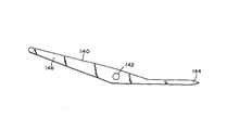
【図10】接合部分を示すタイヤトレッドの拡大側面図。
【図11】図10の11−11線に沿う接合断面図。
【符号の説明】
12 切断ワイヤ
14 第1の端部
16 第2の端部
22,24 コレット
28 円筒形ハウジング
30 ピボットピン
34,38 つまみナット
41 コレット本体
52 フレーム
54 中央連結器
60 偏心器
68 モータ
79 トレッド
87 ロッド[0001]
BACKGROUND OF THE INVENTION
The present invention relates to a method and apparatus for cutting elastomeric materials, and more particularly to an apparatus for cutting elastomeric materials of different cross-sectional shapes having a reinforcing body and a body having a cutting end that is subsequently joined together.
[0002]
[Prior art]
Methods and apparatus for cutting elastomeric materials are known. These conventional cutting techniques include cutting wheels, ultrasound, scissors type and guillotine knives.
[Problems to be solved by the invention]
Guillotine-type knives are somewhat effective, but have drawbacks as well. One drawback is that when the knife penetrates the elastomeric material, the cut surface of the elastomeric material tends to deform. This makes it more difficult to join the ends of the elastomeric material. A second drawback of guillotine knives is that the quality of the cut surface deteriorates when the blade becomes inoperative or when a small portion of the elastomeric material begins to accumulate on the blade. A third drawback is that the blade cannot cut the tire tread at an angle of less than 30 °. Finally, guillotine knives tend to generate heat upon cutting, increasing the temperature of the knife, and in some cases pre-vulcanizing the unvulcanized elastomer at the cutting site. This reduces the ability of the cutting edge to be properly joined.
[0003]
The cutter of the present invention can cut the tread at an angle of less than 30 ° without deformation or pre-vulcanization. This is done quickly and precisely. The cutter also improves the cutting process and improves the bonding surface and bonding quality of the elastomeric material cut by the device.
[0004]
[Means for Solving the Problems]
In accordance with the present invention, a new and improved apparatus for cutting elastomeric material is provided.
[0005]
In particular, there is provided an apparatus for cutting elastomeric material comprising a wire having first and second ends, and first and second securing devices for securing the wire therebetween with tension. The pair of arms support the first and second fixing devices. This arm is pivotally mounted so that it can vibrate when driven by an eccentric mounted on a motor driven rotating shaft. The crossing device creates a relative motion between the wire and the elastomeric material so that the wire cuts through the elastomeric material during vibration.
[0008]
To achieve the above object, an apparatus for cutting an elastomeric material of the present invention comprises an elastomeric material at a predetermined cutting position and angle along a conveyor that supports an elongated body of elastomeric material and has an opening at a predetermined cutting position. An apparatus for cutting an elongate body to a predetermined length, wherein the cutting assembly moves through an opening and is mounted to swing on the cutting assembly and on a spaced arm Each end includes a cutting wire supported, and each arm is connected to an oscillating attachment for oscillating the arm, and each arm is oscillated around the oscillating attachment. A cutting assembly including drive means for reciprocating the cutting wire to form a slit in the elongated body of elastomeric material, and for extending the slit through the elongated body at a predetermined cutting position And means for relatively moving the cutting assembly across the elongate body.
[0009]
In the apparatus for cutting an elastomeric material of the present invention, each end of the cutting wire is fastened by a collet attached to each arm that engages the cutting wire, and each collet pushes the collet to cut the cutting wire. It may have a nut member engaged by tightening.
[0010]
In the apparatus for cutting an elastomeric material of the present invention, each collet may be attached to one of the arms so as to be swingable.
[0012]
【Example】
Hereinafter, an embodiment of the present invention will be described in detail with reference to the drawings. FIG. 1 is a front view of a cutting device according to the present invention. The apparatus has a
[0013]
The first and second ends 14, 16 of the
[0014]
A load is uniformly applied to the
[0015]
As the
[0016]
The spring pin 44 prevents the collet body from rotating when the
[0017]
Referring to FIG. 3A, the
[0018]
1 and 2, the
[0019]
Referring to FIG. 2, the
[0020]
With continued reference to FIGS. 1, 2, and 4,
[0021]
With continued reference to FIGS. 1 and 2, the cutting
[0022]
Referring to FIG. 6, the cutting
[0023]
In operation, an elongated body of elastomeric material, such as the tire tread 70 shown in FIGS. 10 and 11, is placed in the plane P 1 of the belt conveyor support and secured by a securing
[0024]
When the
[0025]
The lap
[0026]
Referring to FIGS. 8 and 9, another embodiment of the present invention in which two cutting assemblies 10A, 10B are attached to one
[0027]
For example, the cutting wires 12A and 12B are attached to vibrating
[0028]
A
[0029]
The members 121A and 121B supported on the drums 128A and 128B are fixed by fixing
[0030]
The apparatus shown in FIGS. 9 and 10 has cutting wires 12A and 12B, which are acute with respect to the cutting direction and with an acute angle with respect to the support surface or drum surface, and the wires pass through members 127A and 127B. It is arranged to cross. As a result of the cutting pressure being downward and forward, the integrity of the cutting edge resulting from the angular cutting can be maintained.
[0031]
In this embodiment, the first cutting wire 12A vibrates to be 180 ° from the second cutting wire 12B, and minimal vibration is maintained in the combined unit 10B.
[0032]
The invention has been described with reference to the preferred embodiment. Variations and modifications can be made by reading and understanding the specification. Such modifications and variations are covered by the claims.
[Brief description of the drawings]
FIG. 1 is a front view of an apparatus according to the present invention cut along a plane parallel to the cutting plane of the cutter shown partially cut away.
FIG. 2 is an enlarged end view of the fixing device shown in FIG. 1;
FIG. 3 is an enlarged view showing a section of the fixing device shown in FIGS. 1 and 2 in section.
4 is a cross-sectional view taken along line 4-4 of FIG.
5 is a cross-sectional view taken along line 5-5 in FIG.
FIG. 6 is a front view of a laminated fixing device for fixing an elastomer material.
7 is a side view of a clamp part of the clamp shown in FIGS. 8 and 9. FIG.
FIG. 8 is a plan view of another embodiment of the present invention.
9 is a sectional view taken along line 9-9 of FIG.
FIG. 10 is an enlarged side view of a tire tread showing a joint portion.
11 is a cross-sectional view taken along line 11-11 in FIG.
[Explanation of symbols]
12 Cutting wire 14 First end 16
Claims (3)
前記開口部を通って移動するカッター組立体であって、互いに間隔をおいて設けられかつ該カッター組立体上にピボット運動するように取付けられた2つのアームに、両側の端部で支持された切断ワイヤを含み、各アームは該アームを揺動運動させる揺動取付け部を含むカッター組立体と、
前記アームに接続された駆動手段であって、前記各アームを前記揺動取付け部を中心に揺動させ、それによって前記切断ワイヤを往復動させ前記エラストマー材料の細長い本体にスリットを形成する駆動手段と、
前記スリットを前記所定の切断位置で前記細長い本体を切断しながら延ばすように、前記カッター組立体を該細長い本体を横切って相対的に動かす手段と、
を有し、
前記切断ワイヤの前記各端部は、前記各アームに取付けられ該切断ワイヤと係合するコレットによって固定されており、各コレットは、内側ハウジングと、該内側ハウジング内に支持されたコレット本体と、該内側ハウジングの周囲にねじ止めされ、該コレット本体の前記切断ワイヤとの係合固定を促すつまみナットと、を備え、
前記各コレットは、前記切断ワイヤが前記細長い本体を切断中に弓型に変形したときに該コレットの位置で該切断ワイヤにかかる曲げ応力を軽減するように、前記各アームにピボット運動可能に取付けられている装置。A device for supporting an elongated body of elastomeric material and cutting the elongated body to a predetermined length at a predetermined angle at a predetermined cutting position along a conveyor having an opening at a predetermined cutting position. ,
A cutter assembly that moves through the opening, supported at opposite ends by two arms spaced apart from each other and pivotally mounted on the cutter assembly. A cutter assembly including a cutting wire, each arm including a swing attachment for swinging the arm;
Drive means connected to the arms, wherein the arms swing about the swing mounting portion, thereby causing the cutting wire to reciprocate to form slits in the elongated body of elastomeric material. When,
Means for relatively moving the cutter assembly across the elongated body to extend the slit while cutting the elongated body at the predetermined cutting position;
Have
Each end of the cutting wire is fixed by a collet attached to each arm and engaged with the cutting wire, each collet having an inner housing, a collet body supported in the inner housing, A thumb nut that is screwed around the inner housing to facilitate engagement and fixation of the collet body with the cutting wire ;
Each collet is pivotally attached to each arm so as to reduce bending stress on the cutting wire at the position of the collet when the cutting wire deforms into an arcuate shape while cutting the elongated body Equipment.
選択的に膨張可能な一対のブラッダーであって、前記固定組立体の前記第2の端部は該一対のブラッダーの間を延び、一方の該ブラッダーは膨張させられたときに前記固定組立体を前記細長い本体に向けて回転させ、他方の該ブラッダーは膨張させられたときに前記固定組立体を前記細長い本体から離すように回転させる一対のブラッダーと、
を有する固定装置を備え、
前記第1の端部は、前記細長い本体の外形形状に合致し、該細長い本体を切断しながら動く前記切断ワイヤが通る間隙を形成するようにされている、
請求項2に記載の装置。A plurality of securing assemblies provided adjacent to each other, wherein the securing assemblies are attached to a support pivot at a position between a first end and a second end of the securing assemblies; A plurality of fixation assemblies adapted to engage the elongated body in the vicinity of the cutting position;
A pair of selectively inflatable bladders, wherein the second end of the fixation assembly extends between the pair of bladders, and one of the bladders expands the fixation assembly when inflated. A pair of bladders that rotate toward the elongate body and rotate the fixation assembly away from the elongate body when the other bladder is inflated;
A fixing device having
The first end conforms to the outer shape of the elongated body and is adapted to form a gap through which the cutting wire moves while cutting the elongated body.
The apparatus of claim 2.
Applications Claiming Priority (2)
| Application Number | Priority Date | Filing Date | Title |
|---|---|---|---|
| US299943 | 1994-09-02 | ||
| US08/299,943 US5638732A (en) | 1994-09-02 | 1994-09-02 | Apparatus for cutting of elastomeric materials |
Publications (2)
| Publication Number | Publication Date |
|---|---|
| JPH0871983A JPH0871983A (en) | 1996-03-19 |
| JP3848389B2 true JP3848389B2 (en) | 2006-11-22 |
Family
ID=23156983
Family Applications (1)
| Application Number | Title | Priority Date | Filing Date |
|---|---|---|---|
| JP22203895A Expired - Fee Related JP3848389B2 (en) | 1994-09-02 | 1995-08-30 | Equipment for cutting elastomeric material |
Country Status (20)
| Country | Link |
|---|---|
| US (1) | US5638732A (en) |
| EP (1) | EP0701887B1 (en) |
| JP (1) | JP3848389B2 (en) |
| KR (1) | KR100391529B1 (en) |
| CN (2) | CN1047751C (en) |
| AT (1) | ATE213988T1 (en) |
| AU (1) | AU685974B2 (en) |
| BR (1) | BR9503879A (en) |
| CA (1) | CA2145788A1 (en) |
| CZ (1) | CZ224395A3 (en) |
| DE (1) | DE69525694T2 (en) |
| FI (1) | FI954122A (en) |
| HU (1) | HU218545B (en) |
| MA (1) | MA23662A1 (en) |
| NO (1) | NO953448L (en) |
| NZ (1) | NZ272821A (en) |
| PL (1) | PL179148B1 (en) |
| TR (1) | TR199501084A2 (en) |
| TW (1) | TW340087B (en) |
| ZA (1) | ZA957037B (en) |
Families Citing this family (30)
| Publication number | Priority date | Publication date | Assignee | Title |
|---|---|---|---|---|
| CA2145794A1 (en) * | 1995-01-05 | 1996-07-06 | James Alfred Ii Benzing | Method and apparatus for cutting a cord reinforced elastomeric laminate |
| US6109322A (en) * | 1995-12-15 | 2000-08-29 | The Goodyear Tire & Rubber Company | Laminate composite structure for making an unvulcanized carcass for a radial ply tire as an intermediate article of manufacture |
| US6336488B1 (en) * | 1995-12-15 | 2002-01-08 | The Goodyear Tire & Rubber Company | Unvulcanized noncord reinforced subassembly for incorporation in a tire casing |
| DE19839045A1 (en) * | 1998-08-28 | 2000-03-02 | Detec Decommissioning Technolo | Method and device for disassembling objects |
| US6510773B1 (en) | 1998-10-20 | 2003-01-28 | The Goodyear Tire And Rubber Company | Method and apparatus for cutting elastomeric materials |
| US6755105B2 (en) * | 2001-06-01 | 2004-06-29 | The Goodyear Tire & Rubber Company | Method and apparatus for cutting elastomeric materials and the article made by the method |
| GB0127643D0 (en) * | 2001-11-17 | 2002-01-09 | Cross Mfg 1938 Company Ltd | A brush seal element |
| US20060070504A1 (en) * | 2004-10-01 | 2006-04-06 | Downing Daniel R | Apparatus for cutting elastomeric materials |
| FR2876392B1 (en) * | 2004-10-07 | 2006-12-15 | Saint Gobain Vetrotex | SYSTEM FOR THE MANUFACTURE OF CUTTING WIRES |
| US7524398B2 (en) * | 2004-12-23 | 2009-04-28 | The Goodyear Tire & Rubber Company | Apparatus for making tire components, and a tire |
| US8561511B2 (en) * | 2004-12-23 | 2013-10-22 | The Goodyear Tire & Rubber Company | Anvil with vacuum width adjustment |
| US20060137804A1 (en) * | 2004-12-23 | 2006-06-29 | Downing Daniel R | Method for making tire ply |
| US20060137814A1 (en) * | 2004-12-23 | 2006-06-29 | Downing Daniel R | Method for making reinforced elastomeric materials |
| US7455002B2 (en) * | 2004-12-23 | 2008-11-25 | The Goodyear Tire & Rubber Company | Method for cutting elastomeric materials and the article made by the method |
| CN100486058C (en) * | 2007-09-03 | 2009-05-06 | 中国电子科技集团公司第二研究所 | Brass wires sending and retreating mechanism of electric plug jack connector assembling equipment |
| CN103128778A (en) * | 2013-03-06 | 2013-06-05 | 江太炎 | Household electric steel wire cutter |
| CN103273514B (en) * | 2013-04-24 | 2014-11-26 | 天津大学 | Thin base material strip cutting and clearing-up integrated device |
| CN104325489B (en) * | 2014-10-15 | 2017-01-11 | 成都东方凯特瑞环保催化剂有限责任公司 | Soft blank cutting method and soft blank cutting device |
| CN104924331B (en) * | 2015-06-06 | 2017-03-08 | 何小平 | A kind of adjustment type plastic pipe cutting device |
| CN105082216B (en) * | 2015-09-14 | 2017-01-18 | 河北工业大学 | Automatic filament cutting mechanism |
| CN105304237B (en) * | 2015-11-13 | 2017-03-22 | 珠海格力新元电子有限公司 | Insulation sleeve opening machine and insulation sleeve opening device thereof |
| US11351691B2 (en) * | 2016-03-11 | 2022-06-07 | Panotec S.R.L. | Machine and method for working a material suitable to make containers |
| CN106393235B (en) * | 2016-11-30 | 2018-02-09 | 内蒙古弘图药业有限公司 | A kind of hand-held Chinese medicine efficient slicer |
| DE102017119279A1 (en) * | 2017-08-23 | 2019-02-28 | Herrmann Ultraschalltechnik Gmbh & Co. Kg | Method for cutting a rubber sheet |
| CN111197203B (en) * | 2020-03-19 | 2021-07-30 | 杰克缝纫机股份有限公司 | Feed lifting thread trimming assembly and sewing machine with feed lifting thread trimming assembly |
| CN111516033B (en) * | 2020-04-30 | 2021-10-08 | 台州市黄岩一鑫汽车零部件有限公司 | Automatic setting die-cutting machine and die-cutting process for polyurethane plastic foam board |
| CN112429563B (en) * | 2020-11-17 | 2023-10-03 | 郑州龙达包装材料有限公司 | Cutting device is used in plastic film processing |
| CN112678576B (en) * | 2020-12-09 | 2023-10-17 | 安徽省绩溪县华宇防火滤料有限公司 | Winding device used in cutting process of fireproof heat-insulating material |
| CN112621850B (en) * | 2020-12-09 | 2023-06-13 | 安徽省绩溪县华宇防火滤料有限公司 | Cutting device for fireproof heat-insulating material |
| CN112775492A (en) * | 2021-01-31 | 2021-05-11 | 刘沛蕾 | Aluminum alloy door and window's processing agency |
Family Cites Families (19)
| Publication number | Priority date | Publication date | Assignee | Title |
|---|---|---|---|---|
| US2735457A (en) * | 1956-02-21 | Raspanti | ||
| US2692622A (en) * | 1953-06-01 | 1954-10-26 | George O Heese | Portable jig saw |
| US3048386A (en) * | 1958-08-15 | 1962-08-07 | Miehle Goss Dexter Inc | Flexible clamp for paper cutters |
| US3138049A (en) * | 1960-04-01 | 1964-06-23 | Goodrich Co B F | Apparatus for cutting sheet or web material |
| US3108350A (en) * | 1960-04-20 | 1963-10-29 | Charles Gunnar Birger Bergling | Sawing device |
| US3220149A (en) * | 1963-11-01 | 1965-11-30 | Dioguardi Reno | Method of cutting metals |
| CA942066A (en) * | 1970-08-28 | 1974-02-19 | Derek H. G. Prowse | Abrasive cutting device |
| US3789712A (en) * | 1972-10-16 | 1974-02-05 | Nrm Corp | Apparatus for severing tire ply stock and the like |
| FR2207780A1 (en) * | 1972-11-27 | 1974-06-21 | Raffard Francis | |
| AU513941B2 (en) * | 1977-06-14 | 1981-01-15 | Cosamia Limited | Lead cropping apparatus |
| DE2843904C2 (en) * | 1978-10-07 | 1984-04-19 | Elmar Dr. 8000 München Messerschmitt | Device for cutting strip-shaped workpieces made of rubber or an elastic plastic |
| DE3444612A1 (en) * | 1984-12-07 | 1986-06-12 | Recticel Deutschland GmbH, 5342 Rheinbreitbach | Vertical cutting machine for foams |
| JPS61237604A (en) * | 1985-04-13 | 1986-10-22 | 日本碍子株式会社 | Cutter for ceramic green ware product |
| US4610653A (en) * | 1985-05-01 | 1986-09-09 | Union Carbide Corporation | Heat sealing and cutting means |
| US4724735A (en) * | 1986-05-06 | 1988-02-16 | Rice Verle L | Blade tensioning mechanism for parallel arm saw |
| US4906145A (en) * | 1987-04-13 | 1990-03-06 | L. R. Oliver & Company, Inc. | Replaceable cutter blade |
| US5058476A (en) * | 1988-07-29 | 1991-10-22 | Shopsmith, Inc. | Scroll saw |
| DK164894C (en) * | 1990-04-11 | 1993-01-25 | Hyma Engineering Aps | MACHINE FOR CUTTING IN TOPICS OF ELASTIC MATERIAL |
| US5299483A (en) * | 1993-02-26 | 1994-04-05 | Sunkist Chemical Machinery Ltd. | Cutting apparatus for foam sponges having irregular contours |
-
1994
- 1994-09-02 US US08/299,943 patent/US5638732A/en not_active Expired - Lifetime
-
1995
- 1995-03-29 CA CA002145788A patent/CA2145788A1/en not_active Abandoned
- 1995-08-15 TW TW084108479A patent/TW340087B/en not_active IP Right Cessation
- 1995-08-21 NZ NZ272821A patent/NZ272821A/en unknown
- 1995-08-22 ZA ZA957037A patent/ZA957037B/en unknown
- 1995-08-24 DE DE69525694T patent/DE69525694T2/en not_active Expired - Fee Related
- 1995-08-24 AT AT95202301T patent/ATE213988T1/en active
- 1995-08-24 EP EP95202301A patent/EP0701887B1/en not_active Expired - Lifetime
- 1995-08-28 HU HU9502524A patent/HU218545B/en not_active IP Right Cessation
- 1995-08-30 JP JP22203895A patent/JP3848389B2/en not_active Expired - Fee Related
- 1995-08-31 PL PL95310239A patent/PL179148B1/en not_active IP Right Cessation
- 1995-08-31 TR TR95/01084A patent/TR199501084A2/en unknown
- 1995-08-31 BR BR9503879A patent/BR9503879A/en not_active IP Right Cessation
- 1995-09-01 KR KR1019950028551A patent/KR100391529B1/en not_active IP Right Cessation
- 1995-09-01 MA MA24004A patent/MA23662A1/en unknown
- 1995-09-01 NO NO953448A patent/NO953448L/en unknown
- 1995-09-01 CZ CZ952243A patent/CZ224395A3/en unknown
- 1995-09-01 CN CN95117175A patent/CN1047751C/en not_active Expired - Fee Related
- 1995-09-01 AU AU30400/95A patent/AU685974B2/en not_active Ceased
- 1995-09-01 FI FI954122A patent/FI954122A/en unknown
-
1999
- 1999-06-19 CN CN99108693A patent/CN1250709A/en active Pending
Also Published As
| Publication number | Publication date |
|---|---|
| HU218545B (en) | 2000-10-28 |
| HUT72773A (en) | 1996-05-28 |
| US5638732A (en) | 1997-06-17 |
| DE69525694T2 (en) | 2002-10-02 |
| FI954122A (en) | 1996-03-03 |
| CN1250709A (en) | 2000-04-19 |
| CZ224395A3 (en) | 1996-05-15 |
| DE69525694D1 (en) | 2002-04-11 |
| EP0701887B1 (en) | 2002-03-06 |
| NZ272821A (en) | 1997-08-22 |
| EP0701887A3 (en) | 1997-02-05 |
| ATE213988T1 (en) | 2002-03-15 |
| EP0701887A2 (en) | 1996-03-20 |
| ZA957037B (en) | 1996-03-26 |
| CN1128693A (en) | 1996-08-14 |
| FI954122A0 (en) | 1995-09-01 |
| KR100391529B1 (en) | 2003-11-14 |
| AU3040095A (en) | 1996-03-14 |
| BR9503879A (en) | 1996-09-17 |
| AU685974B2 (en) | 1998-01-29 |
| NO953448L (en) | 1996-03-04 |
| HU9502524D0 (en) | 1995-10-30 |
| MA23662A1 (en) | 1996-04-01 |
| PL310239A1 (en) | 1996-03-04 |
| TR199501084A2 (en) | 1996-06-21 |
| TW340087B (en) | 1998-09-11 |
| CA2145788A1 (en) | 1996-03-03 |
| PL179148B1 (en) | 2000-07-31 |
| NO953448D0 (en) | 1995-09-01 |
| CN1047751C (en) | 1999-12-29 |
| KR960010513A (en) | 1996-04-20 |
| JPH0871983A (en) | 1996-03-19 |
Similar Documents
| Publication | Publication Date | Title |
|---|---|---|
| JP3848389B2 (en) | Equipment for cutting elastomeric material | |
| EP0483973B1 (en) | Ultrasonic cutting system for stock material | |
| CA2267044C (en) | Strap welding tool with base plate for reducing strap column strength and method therefor | |
| JP2002515335A (en) | Non-node type mounting system for acoustic horn | |
| WO2006011434A1 (en) | Work cutting method and band saw machine | |
| EP0245109A2 (en) | Cleaving optical fibres | |
| JP4354568B2 (en) | Banding tool and method thereof | |
| KR960029082A (en) | Code-reinforced elastomeric laminate cutting method and apparatus | |
| JP2002104838A (en) | Method of cutting optical fiber with coating and device therefor | |
| EP2300217A1 (en) | Resonant nodal mount for linear ultrasonic horns | |
| EP1535727B1 (en) | Device and method for adhering tire component member | |
| JPH10217193A (en) | Cutting device | |
| US20030094077A1 (en) | Method and apparatus for strengthening and leveling a saw blade | |
| JPH1014048A (en) | Method and device for eliminating insulation coating for forming tap of magnet wire | |
| JPH0325272B2 (en) | ||
| JPH07237116A (en) | Lapping processing method and lapping machine | |
| JPS6216733B2 (en) | ||
| JPH08229899A (en) | Unvulcanized rubber material cutting method | |
| JPS61146496A (en) | Cutter |
Legal Events
| Date | Code | Title | Description |
|---|---|---|---|
| A131 | Notification of reasons for refusal |
Free format text: JAPANESE INTERMEDIATE CODE: A131 Effective date: 20050706 |
|
| A521 | Request for written amendment filed |
Free format text: JAPANESE INTERMEDIATE CODE: A523 Effective date: 20050915 |
|
| A131 | Notification of reasons for refusal |
Free format text: JAPANESE INTERMEDIATE CODE: A131 Effective date: 20060405 |
|
| A521 | Request for written amendment filed |
Free format text: JAPANESE INTERMEDIATE CODE: A523 Effective date: 20060630 |
|
| TRDD | Decision of grant or rejection written | ||
| A01 | Written decision to grant a patent or to grant a registration (utility model) |
Free format text: JAPANESE INTERMEDIATE CODE: A01 Effective date: 20060726 |
|
| A61 | First payment of annual fees (during grant procedure) |
Free format text: JAPANESE INTERMEDIATE CODE: A61 Effective date: 20060825 |
|
| R150 | Certificate of patent or registration of utility model |
Free format text: JAPANESE INTERMEDIATE CODE: R150 |
|
| LAPS | Cancellation because of no payment of annual fees |