JP3846829B2 - Steering angle control device for moving body - Google Patents
Steering angle control device for moving body Download PDFInfo
- Publication number
- JP3846829B2 JP3846829B2 JP29726098A JP29726098A JP3846829B2 JP 3846829 B2 JP3846829 B2 JP 3846829B2 JP 29726098 A JP29726098 A JP 29726098A JP 29726098 A JP29726098 A JP 29726098A JP 3846829 B2 JP3846829 B2 JP 3846829B2
- Authority
- JP
- Japan
- Prior art keywords
- steering angle
- steering
- moving body
- guide line
- angle
- Prior art date
- Legal status (The legal status is an assumption and is not a legal conclusion. Google has not performed a legal analysis and makes no representation as to the accuracy of the status listed.)
- Expired - Fee Related
Links
- 238000005259 measurement Methods 0.000 claims description 29
- 238000000034 method Methods 0.000 description 21
- 238000010586 diagram Methods 0.000 description 9
- 230000001133 acceleration Effects 0.000 description 6
- 230000004044 response Effects 0.000 description 5
- 238000004364 calculation method Methods 0.000 description 3
- 230000002123 temporal effect Effects 0.000 description 3
- 238000004519 manufacturing process Methods 0.000 description 2
- 230000004043 responsiveness Effects 0.000 description 2
- 230000032258 transport Effects 0.000 description 2
- 230000000694 effects Effects 0.000 description 1
- 238000002620 method output Methods 0.000 description 1
Images


Description
【0001】
【発明の属する技術分野】
本発明は、操舵輪と固定輪とを備えた無人搬送車の操舵輪に対する操舵角制御装置に関する。
【0002】
【従来の技術】
近年、製造業においては自動化が進んでおり、その生産ラインには無人搬送車に組立て部品を搭載して自動走行させ、組立て部品を所望の目的地まで搬送する自動搬送システムが採用されている。
【0003】
このような自動搬送システムにおける無人搬送車の操舵角制御方式には、操舵輪の位置を制御する操舵輪位置制御型操舵角制御方式と、車体上の基準点の位置を制御する車体位置制御型操舵角制御方式とがある。これらはいずれも以下に説明するように、走行速度によらず走行軌跡が一定になるという特性を持つ制御方式である。
【0004】
操舵輪位置制御型操舵角制御方式は、ガイド線に対する操舵輪位置偏差に応じて、操舵角速度指令値を出力するものである。代表的な操舵輪位置制御型操舵角制御方式には、ガイド式の誘導方式におけるスイングアーム方式がある。
【0005】
スイングアーム方式の操舵角制御方式では、ガイド線40が床面に設けられる。したがって、このガイド線は物理的なガイド線と呼ばれる。これに対し、後で述べるガイドレス式では、ガイド線が仮想的に設定される。したがって、このようなガイド線は仮想的なガイド線と呼ばれる。
【0006】
スイングアーム方式の操舵角制御方式は、図4に示されるように、操舵輪41の操舵軸に取り付けられたスイングアーム42の先端が、常にガイド線40上を移動するように操舵角を制御する方式である。スイングアーム42の先端にはガイド線検出器43が取り付けられており、ガイド線40との位置偏差を検出する構造となっている。44は固定輪である。この他、操舵輪41の位置偏差を計測する手段と、操舵輪41の操舵角αを検出する操舵角センサとを備えている。操舵輪41の位置偏差を計測する手段、操舵角センサはいずれも周知であるが、操舵角センサは、例えば操舵輪に取付けられたエンコーダで実現される。また、位置偏差を計測する手段について言えば、次のような手段が用いられている。床面に、ガイド線40に沿って間隔をおいて複数のターゲットを埋設しておく。これらのターゲットは位置が既知であるので、このターゲットを検出することで操舵輪41の現在位置を計測し、この現在位置のガイド線40からのずれを操舵輪位置偏差として算出する。一方、後で述べる仮想的なガイド線である場合には、GPSによるナビゲーション装置を使用したものが知られている。
【0007】
図5は、図4におけるガイド線40と操舵輪41及びガイド線検出器43の関係を拡大して示した図である。図5では、ガイド線40からの操舵輪41のずれを操舵輪位置偏差ew として示し、操舵角指令値αr 、操舵角計測値αm を示している。スイングアーム42の長さはLである。
【0008】
この制御系は、図6に示されるように、演算部51を含み、操舵輪41のガイド線横断方向の位置制御ループと、その内側にあって演算部52を含む操舵角制御ループとから構成されている。演算部51は、操舵輪位置偏差ew を受けて操舵角指令値αr を出力する。演算部52は、操舵角指令値αr と操舵角計測値αm との差である操舵角偏差を受けて操舵角速度指令値αrvを出力する。操舵角速度指令値αrvは、図示しない操舵モータを駆動するためのアンプを含む駆動部に出力される。
【0009】
以上の制御は、以下の数1に基づいている。
【0010】
【数1】

図7に示されるように、位置制御ループの出力である操舵角指令値αr は、ガイド線横断方向の操舵輪位置偏差ew とスイングア−ム42の長さLで決定される。操舵角速度指令値αrvは、ガイド線検出器43から出力されるガイド線40とガイド線検出器43との位置偏差によって決定される。
【0012】
いま、操舵輪位置偏差ew が小さく線形近似が可能であるとすると、操舵角指令値αr は操舵輪41のガイド線横断方向の速度指令値、操舵角速度指令値αrvはガイド線横断方向での操舵輪41の加速度指令値と見なすことできる。ただし、ここでの速度および加速度は時間に対する微分値ではなく、操舵輪41のガイド線接線方向の移動距離に対する微分値である。
【0013】
従って、この制御系は、操舵輪41のガイド線接線方向の移動距離に対するガイド線横断方向の応答性を規定することになり、結果として操舵輪41の軌跡は走行速度によらず同一となる。
【0014】
一方、ガイドレス式の誘導方式における操舵輪位置制御型操舵角制御方式は、操舵角指令値を仮想的なガイド線に対する操舵輪位置偏差に応じて決定し、さらに操舵角速度指令値を操舵角指令値と実際の操舵角計測値との差である操舵角偏差に応じて決定するものである。これはスイングアーム方式の操舵角制御方式を線形近似したものと同一で、結果として操舵輪の軌跡も同様に走行速度によらず同一となる。
【0015】
これらの操舵輪位置制御型操舵角制御方式の移動体位置の軌跡は以下のようになる。まず、制御対象とする移動体を、図8に示すような車輪配置(1つの操舵輪71、2つの固定輪74)でモデル化し、2つの固定輪74の中間位置を移動体の基準点として定義する。
【0016】
初期条件として操舵輪71が誘導線上にあり、基準点がガイド線70から外れた位置にあるとする。理想的なスイングアーム方式操舵角制御により操舵輪71がガイド線上を誤差無く移動するとすると、基準点の軌跡は以下の数2で近似される。
【0017】
【数2】
【0018】
この式(2)より、移動体の軌跡も、走行速度によらず同一となることがわかる。
【0019】
次に、本発明者により提案されている車体位置制御型操舵角制御方式を図9、図10を参照して説明する。図9においても、1つの操舵輪81と2つの固定輪82とを備え、2つの固定輪82の中間位置を移動体の基準点として定義している。
【0020】
本制御方式は、図10に示す操舵角制御装置に適用される。本操舵角制御装置においては、移動体の位置目標値と位置計測手段による移動体の位置計測値との差が、基準点のガイド線80に対する横断方向位置偏差として算出される。演算部91は、横断方向位置偏差に応じて姿勢角指令値(目標とするガイド線80に対する移動体の向き)を決定する。次に、姿勢角指令値と現在の姿勢角計測値との差が、姿勢角偏差として算出される。演算部92は、姿勢角偏差に応じて操舵角指令値を決定する。更に、操舵角指令値と現在の操舵角計測値の差が、操舵角偏差として算出される。演算部93は、操舵角偏差に応じて操舵角速度指令値を決定する。
【0021】
この操舵角制御を移動体の位置制御として解析すると、姿勢角θや操舵角αが小さく線形近似可能とした場合、姿勢角制御系はガイド線横断方向での基準点位置の速度制御系、操舵角制御系はガイド線横断方向での基準点の加速度制御系と見なすことができる。ただし、ここでの速度および加速度は時間に対する微分値ではなく、基準点のガイド線接線方向の移動距離に対する微分値である。
【0022】
これは、以下の数3で表される。
【0023】
【数3】
従って、この場合の基準点(車体)の軌跡は、走行速度によらず同一となることがわかる。
【0025】
このように、一般的な操舵輪位置制御型操舵角制御方式と新たに提案されている車体位置制御型操舵角制御方式における車輪や移動体の移動軌跡は、走行速度によらず一定のものとなる。ここでは、これらを総称して軌跡一定型操舵角制御方式と呼ぶ。
【0026】
軌跡一定型操舵角制御方式は、ある大きさの制御偏差を修正するために要する時間は走行速度に反比例し、車体横断方向の移動速度が走行速度に比例し、車体横断方向の移動加速度は走行速度の二乗に比例するという特性を持っている。
【0027】
【発明が解決しようとする課題】
無人搬送車のような荷物の搬送を目的とした移動体の場合、操舵角制御性能として要求される性能は、移載位置での停止位置決め精度と、荷崩れを防ぐなめらかな高速走行の2つである。
【0028】
ところが、従来の操舵角制御方式では、移動体や操舵輪の軌跡が走行速度によらず同一となるため、これら2つの要求を同時に満足させることは困難であった。例えば、移動体が移載位置に停止しようとする直前の低速走行区間での位置制御精度が最高になるように制御ゲインを調整すると、高速走行時の応答性が過剰となり不安定な動作となる。一方、高速走行がなめらかになるように制御ゲインを調整した場合には、停止時の停止位置精度が悪化する。
【0029】
そこで、本発明の課題は、あらかじめ定められた経路上を走る移動体に適用される操舵角制御装置であって、高速走行時のなめらかな操舵角操作と、低速走行時の短い走行距離での素早い操舵角操作を実現できる操舵角制御装置を提供することにある。
【0030】
【課題を解決するための手段】
本発明は、操舵輪駆動部によって方向を変えられる操舵輪と、固定輪とを備えた移動体の操舵角制御装置において、移動体にあらかじめ設定された基準点に関して、仮想的ガイド線あるいは物理的ガイド線に対する移動体の相対的な位置を計測する位置計測手段と、前記基準点に関して、仮想的ガイド線あるいは物理的ガイド線に対する移動体の姿勢角を計測する姿勢角計測手段と、前記操舵輪の操舵角を計測する操舵角計測手段と、前記移動体の走行速度を計測して走行速度計測値を出力する速度計測手段と、あらかじめ記憶されている移動体の車輪配置情報と、前記位置計測手段、前記姿勢角計測手段、前記操舵角計測手段、前記速度計測手段の出力とから、操舵角速度指令値を算出し、前記操舵輪駆動部に出力する制御手段とを備え、前記制御手段は、移動体の位置目標値と位置計測値とから算出される位置偏差に基づいて姿勢角指令値を出力し、しかも前記走行速度計測値に応じて第1の制御ゲインを自動的に変更できる第1の制御部と、前記姿勢角指令値と姿勢角計測値とから算出される移動体の姿勢角偏差と前記車輪配置情報とに基づいて操舵角指令値を出力し、しかも前記走行速度計測値に応じて第2の制御ゲインを自動的に変更できる第2の制御部と、前記操舵角指令値と操舵角計測値とから算出される移動体の操舵角偏差に基づいて操舵角速度指令値を出力する第3の制御部とを含み、前記第1の制御部は、前記第1の制御ゲインを前記走行速度計測値に反比例させて自動的に変化させることを特徴とする。
【0032】
また、前記第2の制御部は、前記第2の制御ゲインを走行速度計測値の二乗に反比例させて自動的に変化させることが好ましい。
【0033】
また、前記姿勢角計測手段として、所定の間隔をおいて設置され、前記物理的ガイド線との間の位置偏差を検出するためのガイド線検出器を2つ備えることにより、これら2つのガイド線検出器によって検出された2つの位置偏差値と前記間隔とから姿勢角を算出することができる。
【0034】
【発明の実施の形態】
本発明が適用される移動体は、図2に示すような車輪配置(1つの操舵輪21、2つの固定輪22)でモデル化できる移動体である。このモデルに該当する移動体としては、1つ以上の固定輪と1つの操舵輪を持つシングルステアの移動体、2つの操舵輪が必ず逆相に動作するカウンターステアの移動体、2つの操舵輪が独立に動作するツインステアの移動体などがある。
【0035】
ここでは、図2に示す移動体モデルを例にその作用を説明する。いま、制御しようとする移動体上の代表点を2つの固定輪22の中間位置とし、基準点として定義する。また、移動体の向き(姿勢角θ)は固定輪22の移動方向と同一の方向として定義する。
【0036】
本発明による操舵角制御装置は、計測手段として、従来と同様に、基準点に関してガイド線20に対する移動体の相対的な位置を計測する位置計測手段と、基準点に関してガイド線20に対する移動体の姿勢角θを計測する姿勢角計測手段と、操舵輪21の操舵角を計測する操舵角センサとを備えている。操舵角制御装置は更に、走行速度計測手段を備えている。なお、姿勢角計測手段には、周知のジャイロセンサを用いることができる。このような計測手段は、仮想的なガイド線の場合も同様である。このような計測手段に加えて、あらかじめ記憶されている移動体の車輪配置情報と、走行速度の計測値と、位置計測手段、姿勢角計測手段、操舵角センサの出力とから、操舵角速度指令値を算出し、操舵輪の駆動部に出力する制御装置を備えている。
【0037】
従来の操舵角制御方式では、位置偏差を修正するのに要する走行距離や基準点の軌跡が走行速度によらず一定であった。これは、ガイド線横断方向基準点位置制御系の空間的応答性が一定になるように制御していることによる。
【0038】
これに対して、本操舵角制御装置は、位置偏差を修正するのに要する走行距離が、高速走行時は長く、低速走行時は短くなるように制御するものである。
【0039】
ここでは、上記制御性能を実現する一例として、位置偏差を修正するのに要する時間が走行速度によらず一定となるように制御するものを説明する。
【0040】
図1は、本発明による操舵角制御装置の主要部の構成を示している。この操舵角制御装置は、第1の制御部11を含む位置制御系と、第2の制御部12を含む姿勢角制御系、第3の制御部13を含む操舵角制御系とを含む。
【0041】
本操舵角制御装置ではまず、位置指令値と現在の位置計測値との差を、基準点のガイド線20に対する横断方向位置偏差として算出する。第1の制御部11は、横断方向位置偏差に応じて姿勢角指令値(目標とするガイド線11に対する移動体の向き)を決定する。なお、第1の制御部11で使用する位置制御ゲインG1は、走行速度計測装置13からの走行速度計測値に反比例させて操作する。
【0042】
次に、姿勢角指令値と現在の姿勢角計測値との差を姿勢角偏差として算出する。第2の制御部12には、移動体の車輪配置情報として、図4で説明したホイールベースHがあらかじめ記憶されている。第2の制御部12は、ホイールベースHと姿勢角偏差に応じて操舵角指令値を決定する。なお、第2の制御部12で使用する姿勢角制御ゲインG2は、走行速度計測装置13からの走行速度計測値の二乗に反比例させて操作する。
【0043】
更に、操舵角指令値と現在の操舵角計測値との差を操舵角偏差として算出する。第3の制御部13は、操舵角偏差に応じて操舵角速度指令値を決定する。これにより得られた操舵角速度指令値を、操舵モータの駆動部に入力することによって、操舵角を変更する。
【0044】
姿勢角θや操舵角αが小さく線形近似が可能とすると、この操舵角制御は移動体の位置制御系として以下のように解祈される。
【0045】
基準点のガイド線横断方向の移動速度は、姿勢角θと移動体の走行速度の積となり、走行速度とは比例関係にある。このため、位置制御ゲインG1を走行速度に反比例するように操作することで、位置制御系の時間的応答を走行速度によらず一定とすることができる。
【0046】
基準点のガイド線横断方向の移動加速度は、操舵角αと移動体の走行速度の関数であり、同一操舵角の場合、走行速度を二乗した値と比例関係にある。このため、姿勢角制御ゲインG2を走行速度の二乗に反比例するように操作することで、姿勢角制御系の時間的応答性を走行速度によらず一定にすることができる。
【0047】
上記では、移動体の挙動を基準点のガイド線横断方向の位置制御系としてとらえ、その制御的な応答性を走行速度によらず一定になるように制御する方法を述べたが、以下に示すような他の方法でもよい。
【0048】
位置制御ゲインG1は必ずしも走行速度に反比例させる必要はなく、任意の走行速度の関数として定義しても良い。
【0049】
姿勢角制御ゲインG2は必ずしも走行速度の二乗に反比例させる必要はなく、任意の走行速度の関数として定義しても良い。
【0050】
位置制御ゲインG1、姿勢角制御ゲインG2とも、必ずしも走行速度に応じて連続的に変化させる必要はなく、多段階の不連続な変化でもよい。
【0051】
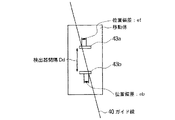
上記の操舵角制御装置が適用可能な位置計測手段の要件は、物理的あるいは仮想的なガイド線に対する移動体の位置と向き(姿勢角)が計測可能であれば良い。従って、平面内での絶対的な移動体の位置と向きが計測可能な、レーザ誘導に代表されるようなガイドレス方式だけでなく、ガイド線に対する相対的な移動体の位置と向きのみ計測可能な図3のようなガイド方式にも適用可能である。
【0052】
図3において、このガイド方式では、移動体に間隔Dd をおいて2つのガイド線検出器43a、43bが備えられ、それぞれ位置偏差ef 、eb が計測される。この場合、姿勢角θは以下の式で算出される。
【0053】
θ=tan-1{(ef +eb )/Dd }
したがって、2つのガイド線検出器43a、43bが姿勢角計測手段を兼ねていることになる。
【0054】
なお、本発明は、無人搬送車、無人フォークリフト、無人ダンプトラック等に適用可能である。
【0055】
【発明の効果】
従来の操舵角制御系の特性は、走行速度によらず移動体の軌跡が同一になるというもので、結果として高速走行時の安定性と高精度な位置決め動作の両立が困難であった。それに対して、本発明の操舵角制御装置では、走行速度によらず位置制御系の時間的な応答性を一定にすることにより、高速走行時には自動的に低ゲインでの制御となることでなめらかな走行を実現する一方、低速走行時には自動的に高ゲインでの制御となることで高精度位置決めを可能とした。
【0056】
これによって、無人搬送車のような荷物を搬送する移動体においては、移載時の停止位置精度の確保と、高速走行中の荷崩れを防止することができる。
【0057】
また、走行速度に応じて自動的に制御ゲインが調整されるため、走行経路の形状や場所に応じて制御系の特性を個別に定義する必要がなく、無人搬送システムを構築する際の設計工数も従来の制御系の場合と同等以下とすることができる。
【図面の簡単な説明】
【図1】本発明による移動体の操舵角制御装置の主要部の構成を示したブロック図である。
【図2】本発明が適用される移動体モデルについて説明するための図である。
【図3】本発明が適用される移動体の他の例の概略構成を示した図である。
【図4】従来の操舵角制御装置を説明するために移動体の概略構成を示した図である。
【図5】図4におけるガイド線と操舵輪及びガイド線検出器の関係を拡大して示した図である。
【図6】従来の操舵角制御装置の主要部の構成を示したブロック図である。
【図7】図6に示された構成要素の機能を説明するための図である。
【図8】従来の操舵輪位置制御型操舵角制御方式の移動体モデルを説明するために移動体の概略構成を示した図である。
【図9】本発明者により提案されている車体位置制御型操舵角制御装置を適用するための移動体の概略構成を示した図である。
【図10】図9の移動体に適用される車体位置制御型操舵角制御装置の主要部の構成を示したブロック図である。
【符号の説明】
20、40、70 ガイド線
21、41、71 操舵輪
22、44、74 固定輪
42、72 スイングアーム
43、73 ガイド線検出器[0001]
BACKGROUND OF THE INVENTION
The present invention relates to a steering angle control device for a steering wheel of an automatic guided vehicle having a steering wheel and a fixed wheel.
[0002]
[Prior art]
In recent years, automation has progressed in the manufacturing industry, and an automatic conveyance system is employed in the production line, in which an assembly part is mounted on an automatic guided vehicle and automatically traveled to convey the assembly part to a desired destination.
[0003]
The steering angle control method of the automatic guided vehicle in such an automatic conveyance system includes a steering wheel position control type steering angle control method for controlling the position of the steering wheel and a vehicle body position control type for controlling the position of the reference point on the vehicle body. There is a steering angle control system. Each of these is a control method having a characteristic that the traveling locus becomes constant regardless of the traveling speed, as described below.
[0004]
The steering wheel position control type steering angle control method outputs a steering angular velocity command value according to a steering wheel position deviation with respect to a guide line. As a typical steering wheel position control type steering angle control method, there is a swing arm method in a guide type guidance method.
[0005]
In the swing arm type steering angle control method, the guide wire 40 is provided on the floor surface. Therefore, this guide line is called a physical guide line. On the other hand, in the guideless type described later, a guide line is virtually set. Therefore, such a guide line is called a virtual guide line.
[0006]
As shown in FIG. 4, the swing angle type steering angle control method controls the steering angle so that the tip of the swing arm 42 attached to the steering shaft of the
[0007]
FIG. 5 is an enlarged view showing the relationship between the guide line 40, the steered
[0008]
As shown in FIG. 6, the control system includes a
[0009]
The above control is based on the following formula 1.
[0010]
[Expression 1]
As shown in FIG. 7, the steering angle command value α r that is the output of the position control loop is determined by the steering wheel position deviation e w in the guide line crossing direction and the length L of the swing arm 42. The steering angular velocity command value α rv is determined by the positional deviation between the guide line 40 and the guide line detector 43 output from the guide line detector 43.
[0012]
Assuming that the steering wheel position deviation ew is small and linear approximation is possible, the steering angle command value α r is the speed command value of the
[0013]
Therefore, this control system defines the responsiveness in the guide line transverse direction with respect to the travel distance of the steered
[0014]
On the other hand, the steering wheel position control type steering angle control method in the guideless guidance method determines the steering angle command value according to the steering wheel position deviation with respect to the virtual guide line, and further determines the steering angular velocity command value as the steering angle command. It is determined according to the steering angle deviation which is the difference between the value and the actual measured steering angle value. This is the same as a linear approximation of the swing angle type steering angle control method. As a result, the trajectory of the steered wheels is also the same regardless of the traveling speed.
[0015]
The locus of the moving body position in these steering wheel position control type steering angle control systems is as follows. First, a moving object to be controlled is modeled by a wheel arrangement (one steering wheel 71, two fixed wheels 74) as shown in FIG. 8, and an intermediate position between the two
[0016]
As an initial condition, it is assumed that the steered wheel 71 is on the guide line and the reference point is at a position away from the
[0017]
[Expression 2]
[0018]
From this equation (2), it can be seen that the trajectory of the moving body is the same regardless of the traveling speed.
[0019]
Next, the vehicle body position control type steering angle control method proposed by the present inventor will be described with reference to FIGS. Also in FIG. 9, one
[0020]
This control method is applied to the steering angle control device shown in FIG. In the present steering angle control device, the difference between the position target value of the moving body and the position measurement value of the moving body by the position measuring means is calculated as a lateral position deviation with respect to the guide line 80 of the reference point. The calculation unit 91 determines the posture angle command value (the direction of the moving body with respect to the target guide line 80) according to the cross-directional deviation. Next, a difference between the attitude angle command value and the current attitude angle measurement value is calculated as an attitude angle deviation. The
[0021]
When this steering angle control is analyzed as the position control of the moving body, when the attitude angle θ and the steering angle α are small and linear approximation is possible, the attitude angle control system is a speed control system for the reference point position in the guide line crossing direction, steering The angle control system can be regarded as a reference point acceleration control system in the guide line crossing direction. However, the speed and acceleration here are not differential values with respect to time but differential values with respect to the movement distance of the reference point in the tangential direction of the guide line.
[0022]
This is expressed by Equation 3 below.
[0023]
[Equation 3]
Therefore, it can be seen that the trajectory of the reference point (vehicle body) in this case is the same regardless of the traveling speed.
[0025]
As described above, the movement trajectory of the wheels and the moving body in the general steering wheel position control type steering angle control method and the newly proposed vehicle body position control type steering angle control method is constant regardless of the traveling speed. Become. Here, these are collectively referred to as a constant trajectory steering angle control method.
[0026]
In the constant trajectory type steering angle control method, the time required to correct a certain amount of control deviation is inversely proportional to the traveling speed, the moving speed in the transverse direction of the vehicle is proportional to the traveling speed, and the moving acceleration in the transverse direction of the vehicle is equal to the traveling speed. It has the property of being proportional to the square of speed.
[0027]
[Problems to be solved by the invention]
In the case of a mobile body for the purpose of transporting luggage such as an automatic guided vehicle, two performances required as steering angle control performance are stop positioning accuracy at the transfer position and smooth high-speed traveling to prevent load collapse. It is.
[0028]
However, in the conventional steering angle control system, the trajectories of the moving body and the steered wheels are the same regardless of the traveling speed, and it is difficult to satisfy these two requirements at the same time. For example, if the control gain is adjusted so that the position control accuracy in the low-speed traveling section immediately before the moving body tries to stop at the transfer position is maximum, the response at the time of high-speed traveling becomes excessive and the operation becomes unstable. . On the other hand, when the control gain is adjusted so that the high-speed running is smooth, the stop position accuracy at the time of stop is deteriorated.
[0029]
Accordingly, an object of the present invention is a steering angle control device that is applied to a moving body that runs on a predetermined route, in which a smooth steering angle operation during high-speed traveling and a short traveling distance during low-speed traveling are performed. An object of the present invention is to provide a steering angle control device capable of realizing a quick steering angle operation.
[0030]
[Means for Solving the Problems]
The present invention relates to a steering angle control device for a moving body including a steering wheel whose direction can be changed by a steering wheel driving unit and a fixed wheel, and a virtual guide line or a physical point for a reference point set in advance on the moving body. Position measuring means for measuring the relative position of the moving body with respect to the guide line, attitude angle measuring means for measuring the attitude angle of the moving body with respect to a virtual guide line or a physical guide line with respect to the reference point, and the steering wheel Steering angle measuring means for measuring the steering angle of the vehicle, speed measuring means for measuring the traveling speed of the mobile body and outputting a travel speed measurement value, wheel arrangement information of the mobile body stored in advance, and the position measurement Control means for calculating a steering angular speed command value from the output of the attitude angle measuring means, the steering angle measuring means, and the speed measuring means, and outputting the steering angular speed command value to the steering wheel drive unit, The control means outputs a posture angle command value based on the position deviation calculated from the position target value and the position measurement value of the moving body, and automatically sets the first control gain according to the travel speed measurement value. A steering angle command value based on the attitude angle deviation of the moving body calculated from the attitude angle command value and the attitude angle measurement value and the wheel arrangement information, and Steering based on a steering angle deviation of the moving body calculated from the steering angle command value and the steering angle measurement value, a second control unit that can automatically change the second control gain in accordance with the travel speed measurement value look including a third control unit for outputting an angular velocity instruction value, the first control unit is characterized by automatically changing the first control gain in inverse proportion to the traveling speed measured value .
[0032]
Further, it is preferable that the second control unit automatically changes the second control gain in inverse proportion to the square of the travel speed measurement value.
[0033]
Further, as the posture angle measuring means, two guide line detectors are provided that are installed at a predetermined interval and detect a positional deviation between the physical guide lines, and thereby the two guide lines are detected. The posture angle can be calculated from the two position deviation values detected by the detector and the interval.
[0034]
DETAILED DESCRIPTION OF THE INVENTION
The moving body to which the present invention is applied is a moving body that can be modeled with a wheel arrangement (one
[0035]
Here, the operation will be described taking the moving body model shown in FIG. 2 as an example. Now, a representative point on the moving body to be controlled is defined as a reference point, which is an intermediate position between the two fixed
[0036]
In the steering angle control device according to the present invention, as the measurement means, the position measurement means for measuring the relative position of the moving body with respect to the
[0037]
In the conventional steering angle control method, the travel distance and the reference point trajectory required for correcting the position deviation are constant regardless of the travel speed. This is because control is performed so that the spatial responsiveness of the reference point position control system in the guide line crossing direction is constant.
[0038]
On the other hand, the present steering angle control device performs control so that the travel distance required to correct the position deviation is long during high speed travel and short during low speed travel.
[0039]
Here, as an example for realizing the above-described control performance, a description will be given of control in which the time required to correct the position deviation is constant regardless of the traveling speed.
[0040]
FIG. 1 shows a configuration of a main part of a steering angle control device according to the present invention. The steering angle control device includes a position control system including a first control unit 11, a posture angle control system including a
[0041]
In the present steering angle control device, first, the difference between the position command value and the current position measurement value is calculated as a lateral position deviation with respect to the
[0042]
Next, a difference between the attitude angle command value and the current attitude angle measurement value is calculated as an attitude angle deviation. In the
[0043]
Further, a difference between the steering angle command value and the current steering angle measurement value is calculated as a steering angle deviation. The
[0044]
If the posture angle θ and the steering angle α are small and linear approximation is possible, this steering angle control is solved as follows as a position control system of the moving body.
[0045]
The moving speed of the reference point in the direction crossing the guide line is the product of the posture angle θ and the traveling speed of the moving body, and is proportional to the traveling speed. For this reason, by operating the position control gain G1 in inverse proportion to the traveling speed, the temporal response of the position control system can be made constant regardless of the traveling speed.
[0046]
The movement acceleration of the reference point in the direction crossing the guide line is a function of the steering angle α and the traveling speed of the moving body, and is proportional to the square of the traveling speed when the steering angle is the same. Therefore, by operating the attitude angle control gain G2 so as to be inversely proportional to the square of the traveling speed, the temporal response of the attitude angle control system can be made constant regardless of the traveling speed.
[0047]
In the above, the method of controlling the behavior of the moving body as a position control system in the direction crossing the guide line of the reference point and controlling the control response so as to be constant regardless of the traveling speed is described below. Other methods may be used.
[0048]
The position control gain G1 does not necessarily have to be inversely proportional to the traveling speed, and may be defined as a function of an arbitrary traveling speed.
[0049]
The attitude angle control gain G2 is not necessarily inversely proportional to the square of the traveling speed, and may be defined as a function of an arbitrary traveling speed.
[0050]
Both the position control gain G1 and the posture angle control gain G2 do not necessarily need to be continuously changed according to the traveling speed, and may be multistage discontinuous changes.
[0051]
The position measuring means to which the steering angle control device can be applied only needs to be able to measure the position and orientation (posture angle) of the moving body with respect to a physical or virtual guide line. Therefore, it is possible to measure the position and orientation of the moving body relative to the guide line as well as the guideless system represented by laser guidance, which can measure the absolute position and orientation of the moving body in the plane. The present invention can also be applied to a guide system as shown in FIG.
[0052]
3, this guide system, two guide-
[0053]
θ = tan −1 {(e f + e b ) / D d }
Therefore, the two
[0054]
The present invention can be applied to an automatic guided vehicle, an automatic forklift, an automatic dump truck, and the like.
[0055]
【The invention's effect】
The characteristic of the conventional steering angle control system is that the trajectory of the moving body is the same regardless of the traveling speed. As a result, it is difficult to achieve both stability during high-speed traveling and highly accurate positioning operation. On the other hand, the steering angle control device of the present invention makes smooth control by automatically controlling with low gain during high-speed driving by making the temporal response of the position control system constant regardless of the driving speed. On the other hand, high-precision positioning is possible by automatically controlling with high gain during low-speed driving.
[0056]
As a result, in a moving body that transports a load such as an automatic guided vehicle, it is possible to ensure the accuracy of the stop position during transfer and to prevent collapse of the load during high-speed travel.
[0057]
In addition, since the control gain is automatically adjusted according to the travel speed, there is no need to individually define the characteristics of the control system according to the shape and location of the travel route, and the design man-hours for constructing the unmanned transport system Also, it can be equal to or less than that of the conventional control system.
[Brief description of the drawings]
FIG. 1 is a block diagram showing a configuration of a main part of a steering angle control device for a moving body according to the present invention.
FIG. 2 is a diagram for explaining a moving object model to which the present invention is applied.
FIG. 3 is a diagram showing a schematic configuration of another example of a moving body to which the present invention is applied.
FIG. 4 is a diagram showing a schematic configuration of a moving body in order to explain a conventional steering angle control device.
5 is an enlarged view showing the relationship between a guide line, a steered wheel, and a guide line detector in FIG. 4;
FIG. 6 is a block diagram showing a configuration of a main part of a conventional steering angle control device.
7 is a diagram for explaining functions of the components shown in FIG. 6; FIG.
FIG. 8 is a diagram showing a schematic configuration of a moving body in order to explain a conventional moving body model of a steering wheel position control type steering angle control system.
FIG. 9 is a diagram showing a schematic configuration of a moving body to which the vehicle body position control type steering angle control device proposed by the present inventor is applied.
10 is a block diagram illustrating a configuration of a main part of a vehicle body position control type steering angle control device applied to the moving body of FIG. 9;
[Explanation of symbols]
20, 40, 70
Claims (3)
移動体にあらかじめ設定された基準点に関して、仮想的ガイド線あるいは物理的ガイド線に対する移動体の相対的な位置を計測する位置計測手段と、
前記基準点に関して、仮想的ガイド線あるいは物理的ガイド線に対する移動体の姿勢角を計測する姿勢角計測手段と、
前記操舵輪の操舵角を計測する操舵角計測手段と、
前記移動体の走行速度を計測して走行速度計測値を出力する速度計測手段と、
あらかじめ記憶されている移動体の車輪配置情報と、前記位置計測手段、前記姿勢角計測手段、前記操舵角計測手段、前記速度計測手段の出力とから、操舵角速度指令値を算出し、前記操舵輪駆動部に出力する制御手段とを備え、
前記制御手段は、
移動体の位置目標値と位置計測値とから算出される位置偏差に基づいて姿勢角指令値を出力し、しかも前記走行速度計測値に応じて第1の制御ゲインを自動的に変更できる第1の制御部と、
前記姿勢角指令値と姿勢角計測値とから算出される移動体の姿勢角偏差と前記車輪配置情報とに基づいて操舵角指令値を出力し、しかも前記走行速度計測値に応じて第2の制御ゲインを自動的に変更できる第2の制御部と、
前記操舵角指令値と操舵角計測値とから算出される移動体の操舵角偏差に基づいて操舵角速度指令値を出力する第3の制御部とを含み、
前記第1の制御部は、前記第1の制御ゲインを前記走行速度計測値に反比例させて自動的に変化させることを特徴とする操舵角制御装置。In a steering angle control device for a moving body including a steering wheel whose direction can be changed by a steering wheel driving unit and a fixed wheel,
Position measuring means for measuring a relative position of the moving body with respect to a virtual guide line or a physical guide line with respect to a reference point set in advance on the moving body;
Posture angle measuring means for measuring the posture angle of the moving body with respect to the virtual guide line or the physical guide line with respect to the reference point;
Steering angle measuring means for measuring the steering angle of the steering wheel;
Speed measuring means for measuring a traveling speed of the moving body and outputting a traveling speed measurement value;
A steering angular velocity command value is calculated from wheel arrangement information of the moving body stored in advance and outputs of the position measuring means, the attitude angle measuring means, the steering angle measuring means, and the speed measuring means, and the steering wheel Control means for outputting to the drive unit,
The control means includes
A posture angle command value is output based on a position deviation calculated from a position target value and a position measurement value of the moving body, and the first control gain can be automatically changed according to the travel speed measurement value. A control unit of
A steering angle command value is output based on the posture angle deviation of the moving body calculated from the posture angle command value and the posture angle measurement value and the wheel arrangement information, and a second value is determined according to the travel speed measurement value. A second control unit that can automatically change the control gain;
The saw including a third control unit for outputting a steering angular velocity command value based on the steering angle deviation of the moving object is calculated from the steering angle command value and the steering angle measured value,
The steering angle control device , wherein the first control unit automatically changes the first control gain in inverse proportion to the travel speed measurement value .
Priority Applications (1)
| Application Number | Priority Date | Filing Date | Title |
|---|---|---|---|
| JP29726098A JP3846829B2 (en) | 1998-10-19 | 1998-10-19 | Steering angle control device for moving body |
Applications Claiming Priority (1)
| Application Number | Priority Date | Filing Date | Title |
|---|---|---|---|
| JP29726098A JP3846829B2 (en) | 1998-10-19 | 1998-10-19 | Steering angle control device for moving body |
Publications (2)
| Publication Number | Publication Date |
|---|---|
| JP2000122722A JP2000122722A (en) | 2000-04-28 |
| JP3846829B2 true JP3846829B2 (en) | 2006-11-15 |
Family
ID=17844230
Family Applications (1)
| Application Number | Title | Priority Date | Filing Date |
|---|---|---|---|
| JP29726098A Expired - Fee Related JP3846829B2 (en) | 1998-10-19 | 1998-10-19 | Steering angle control device for moving body |
Country Status (1)
| Country | Link |
|---|---|
| JP (1) | JP3846829B2 (en) |
Families Citing this family (2)
| Publication number | Priority date | Publication date | Assignee | Title |
|---|---|---|---|---|
| CN106843245B (en) * | 2016-12-01 | 2022-02-01 | 北京京东乾石科技有限公司 | Unmanned aerial vehicle attitude control method and device and unmanned aerial vehicle |
| KR20210044766A (en) * | 2018-09-10 | 2021-04-23 | 도쿄 케이키 가부시키가이샤 | Automatic steering control device |
-
1998
- 1998-10-19 JP JP29726098A patent/JP3846829B2/en not_active Expired - Fee Related
Also Published As
| Publication number | Publication date |
|---|---|
| JP2000122722A (en) | 2000-04-28 |
Similar Documents
| Publication | Publication Date | Title |
|---|---|---|
| WO2017158973A1 (en) | Automatic guided vehicle | |
| WO1996015483A1 (en) | Guidance system for vehicle | |
| JP2018194937A (en) | Travel control device and travel control method of unmanned carrier | |
| JPH075922A (en) | Steering control method for unmanned work vehicle | |
| JP3846829B2 (en) | Steering angle control device for moving body | |
| JP3378843B2 (en) | Correction device for position and direction of automatic guided vehicle | |
| JP3846828B2 (en) | Steering angle control device for moving body | |
| CN114089730B (en) | Robot motion planning method and automatic guiding vehicle | |
| JP2000153988A (en) | Trackless road surface traveling body and container terminal | |
| JP4269170B2 (en) | Trajectory tracking control method and apparatus | |
| JP2622579B2 (en) | How to guide moving objects | |
| JP2002108453A (en) | Unmanned vehicle | |
| CN113835425A (en) | Path planning method | |
| JPH07129243A (en) | Controller for steering unmanned vehicle | |
| KR100199988B1 (en) | Steering method and device of agv | |
| JPH07101369B2 (en) | Automatic steering control system | |
| JPS61139807A (en) | Running controller of unattended running car | |
| JPH08202449A (en) | Automatic operation controller for carring truck | |
| TWI708129B (en) | Cooperative system and controlling method for autonomous guided vehicle | |
| JPH04107711A (en) | Controller for omnidirectional mobile vehicle | |
| JP2001042934A (en) | Method for correcting estimated position of automated guided vehicle and device therefor | |
| JPS6339923B2 (en) | ||
| JPH0981240A (en) | Method for controlling traveling of autonomously traveling automated guided vehicle | |
| JPS6170616A (en) | Course run guidance system of automatic running body | |
| JP3735897B2 (en) | Unmanned vehicle guidance system |
Legal Events
| Date | Code | Title | Description |
|---|---|---|---|
| A977 | Report on retrieval |
Free format text: JAPANESE INTERMEDIATE CODE: A971007 Effective date: 20060323 |
|
| A131 | Notification of reasons for refusal |
Free format text: JAPANESE INTERMEDIATE CODE: A131 Effective date: 20060412 |
|
| A521 | Request for written amendment filed |
Free format text: JAPANESE INTERMEDIATE CODE: A523 Effective date: 20060609 |
|
| TRDD | Decision of grant or rejection written | ||
| A01 | Written decision to grant a patent or to grant a registration (utility model) |
Free format text: JAPANESE INTERMEDIATE CODE: A01 Effective date: 20060816 |
|
| A61 | First payment of annual fees (during grant procedure) |
Free format text: JAPANESE INTERMEDIATE CODE: A61 Effective date: 20060821 |
|
| R150 | Certificate of patent or registration of utility model |
Free format text: JAPANESE INTERMEDIATE CODE: R150 |
|
| S531 | Written request for registration of change of domicile |
Free format text: JAPANESE INTERMEDIATE CODE: R313531 |
|
| FPAY | Renewal fee payment (event date is renewal date of database) |
Free format text: PAYMENT UNTIL: 20090901 Year of fee payment: 3 |
|
| R350 | Written notification of registration of transfer |
Free format text: JAPANESE INTERMEDIATE CODE: R350 |
|
| FPAY | Renewal fee payment (event date is renewal date of database) |
Free format text: PAYMENT UNTIL: 20100901 Year of fee payment: 4 |
|
| FPAY | Renewal fee payment (event date is renewal date of database) |
Free format text: PAYMENT UNTIL: 20110901 Year of fee payment: 5 |
|
| FPAY | Renewal fee payment (event date is renewal date of database) |
Free format text: PAYMENT UNTIL: 20120901 Year of fee payment: 6 |
|
| FPAY | Renewal fee payment (event date is renewal date of database) |
Free format text: PAYMENT UNTIL: 20130901 Year of fee payment: 7 |
|
| LAPS | Cancellation because of no payment of annual fees |