JP3845748B2 - Repair method for existing buried pipe - Google Patents
Repair method for existing buried pipe Download PDFInfo
- Publication number
- JP3845748B2 JP3845748B2 JP2003206144A JP2003206144A JP3845748B2 JP 3845748 B2 JP3845748 B2 JP 3845748B2 JP 2003206144 A JP2003206144 A JP 2003206144A JP 2003206144 A JP2003206144 A JP 2003206144A JP 3845748 B2 JP3845748 B2 JP 3845748B2
- Authority
- JP
- Japan
- Prior art keywords
- hose
- repair method
- curing
- cured
- backfill material
- Prior art date
- Legal status (The legal status is an assumption and is not a legal conclusion. Google has not performed a legal analysis and makes no representation as to the accuracy of the status listed.)
- Expired - Fee Related
Links
Images

Description
【0001】
【発明の属する技術分野】
本発明は既設埋設管の補修工法、特に既設下水道管の更生に適用して有用な既設埋設管の補修工法に関する。
【0002】
【従来の技術】
従来、既設埋設管の補修工法として、埋設管の内周面を周隙を存してライニング材により覆って後、上記周隙内に裏込め材を充填し養生硬化させる工法がよく知られている。上記補修工法において、ライニング材としては、一般に背面リブ付きのプラスチック板材が使用され、施工後に於いては、ライニング材の背面リブが裏込め材の養生硬化層内に埋設され、アンカー部として機能し、この背面リブのアンカー効果によりライニング材を養生硬化層を介し既設埋設管の内周面に対し取り付け固定できる構成になっている。
【0003】
【発明が解決しようとする課題】
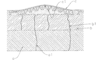
補修対象の埋設管は長年の埋設使用により老朽化が進んでおり、例えばコンクリート製の下水道管に於いては管継ぎ手部や本管部のクラック部分を通じて管内に向け地下水が浸入することが多く、ライニング施工後において、ライニング材が浸入地下水の水圧を受けて剥離膨出する等のトラブルを生ずることがあった。図8は、ライニング施工後における地下水の浸入並びにライニング材の剥離膨出状況を概略的に示し、地下水(矢符参照)は既設管aの管継ぎ手部(図示せず)やクラックa1から裏込め材の養生硬化層bのクラックb1などを通ってライニング材cの背面まで浸入し、ライニング材cの背面圧力を地下水位に相当する圧力まで上昇させる。因みに大口径(例えば口径1〜3m程度)下水道管の場合、埋設深度(地表面からの埋設深さ)が比較的大きく、例えば埋設深度ひいては地下水位としては最大で20m程度に達することがあり、この場合、ライニング材cの背面圧力は最大で2kg/cm2程度まで上昇することが予想される。このようなライニング材cの背面圧力の上昇は、養生硬化層bからの背面リブc1の抜け出しひいてはライニング材cの剥離を発生させ、一旦剥離が生ずると剥離は徐々に周囲に広がって行き剥離部分が管内方に向け膨出しライニング不良を招くことになり、このような傾向は養生硬化層bが本来の強度を未だ発現するに至っていない養生硬化の初期段階において顕著である。
【0004】
本発明は、地下水の浸入に拘わらずライニング材のライニング状態を長期間に亘り安定確実に持続保持できる、特に大口径の既設下水道管の更生に適用して有用な既設埋設管の補修工法を提供することを目的としてなされたものである。
【0005】
【課題を解決するための手段】
本発明は、補修対象の既設埋設管の内周全面を背面リブ付きライニング材により周隙を存して覆って後、上記周隙内に裏込め材を注入充填し養生硬化させる既設埋設管の補修工法において、裏込め材の注入充填工程より前の工程で、上記周隙内に管軸方向の全長に亘って少なくとも1本のホースを設置しておき、該ホースを該ホース内充填の流体により形状保持した状態で裏込め材の注入充填と養生硬化を行い、しかる後、裏込め材の養生硬化層内からホースを抜脱し、抜脱跡を浸入地下水の排出通路として利用することを特徴とする既設埋設管の補修工法に係る。
【0006】
本発明の好ましい一実施態様によれば、排出通路の排出口に該通路内から外部に開く逆止弁を備え、該通路内に浸入の地下水を逆止弁を通じ通路外に排出することが出来る。また上記ホースの抜脱を、裏込め材の養生硬化の初期段階において反転抜き出し手段を適用して行うことができる。本発明補修工法は、特に大口径のコンクリート製下水道管の更生に適用して有用である。
【0007】
【発明の実施の形態】
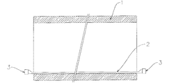
以下に本発明の一実施形態を添付図面に基づき説明する。図1〜5は本発明補修工法を工程順に示す概略説明図であり、本発明工法の実施に際しては、まず最初に、図1に示すように補修対象の既設埋設管、例えば下水道管1の好ましくは管底部に管軸方向の全長に亘ってホース2を設置し、該ホース2の両端部には流体、例えば水の給排機能(図示せず)を備えた栓3、3を施しておく。
【0008】
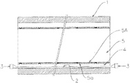
ホース1の設置を終えた後は、図2に示すように、下水道管1の内周面の全面を周隙4を存して覆うように背面リブ5a付きライニング材5から管状のライニング部5Aを組み立てる。このような背面リブ5a付きライニング材5適用による管状ライニング部5Aの組み立ては、従来の補修工法と実質的に異なるところがなく、従来工法に従い行えばよい。
【0009】
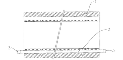
管状ライニング部5Aの組み立てを終えた後は、図3に示すように、ホース2内に栓3を通じ流体例えば水を充填し、ホース2を膨張状態に保持する。水は非圧縮性で形状保持性に優れ又給排に便利であり適しているが、他の流体を適用してもよい。
【0010】
ホース2の膨張を終えた後は、図4に示すように、下水道管1と管状ライニング部5Aとの間の周隙4内に従来工法と同様に裏込め材6(例えばセメントミルク)の注入充填を行い、しかる後、該裏込め材6の養生硬化を行う。因みに裏込め材の注入充填は、周隙という狭い環状空間部を十分確実に満たすために、従来工法と同様に、裏込め材を周隙4の頂部から供給しつつ流下充填させていくという手段がとられる。このような充填手段ではどうしても裏込め材が流下時に空気を巻き込み気泡を発生し易く、この気泡が原因で、養生硬化後に気孔やクラックを発生することがある。又、裏込め材の硬化収縮によって、クラックが発生することも多い。よって裏込め材6の養生硬化層は、従来工法と同様に、地下水が浸入した場合、浸入地下水をライニング材5に向けて通過させてしまう。
【0011】
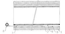
養生硬化により、裏込め材6が初期硬化しある程度の強度を保持するに至った後は、図5に示すようにホース2内より水を排出しホース2内の圧力を開放し、更に両端部の栓3、3を取り外したのち、ホース2内にワイヤー7を通線し、通線ワイヤー7を利用しウインチ8等の作動をしてホース2を反転状態のもとに裏込め材6の層内より抜き出すと、ホース2の抜き出し跡に、地下水の排出通路9が形成される。
【0012】
ホース2は容易に反転できるような樹脂製の薄肉ホースを使用すればよい。例えば口径が50mm程度の場合では、肉厚が0.3〜1mmのポリエチレン製のホースを使用することができる。ポリエチレンはセメント系裏込め材との付着性が極めて低いため、反転状態すなわち裏返しながら引っ張ることで容易に剥離できて抜き出すことができる。
【0013】
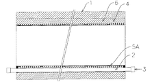
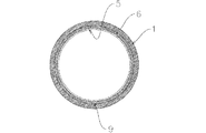
図6、7は排出通路9の形成状況を示し、該排出通路9は施工後にライニング材5の背面まで浸入した地下水を外部に排出する働きをし、ライニング材5を地下水圧から開放する。而して本発明補修工法によれば、下水道管1並びに裏込め材6の養生硬化層を通じ、仮に地下水の浸入が発生したとしても、ライニング材5は実質的に地下水圧を受けることが無くなり、施工後、長期間にわたりライニング状態を安定確実に保持することが出来る。尚、排出通路9内への下水等の逆流を防止するために、該通路9の排出口に逆止弁10(図7参照)を備えることが出来る。
【0014】
【発明の効果】
本発明によれば、地下水の浸入に拘わらずライニング材のライニング状態を長期間に亘り安定確実に持続保持できる、特に大口径の既設下水道管の更生に適用して有用な既設埋設管の補修工法を提供することが出来る。
【図面の簡単な説明】
【図1】本発明補修工法におけるホースの設置工程の状況を概略的に示す説明図である。
【図2】同、上記ホース設置工程に引き続き行われるライニング工程の状況を概略的に示す説明図である。
【図3】同、上記ライニング工程に引き続き行われるホース膨張行程の状況を概略的に示す説明図である。
【図4】同、上記ホース膨張行程に引き続き行われる裏込め材の注入充填並びに養生硬化工程の概略的に示す説明図である。
【図5】上記養生硬化工程に引き続き行われるホースの抜脱工程の状況を概略的に示す説明図である。
【図6】本発明補修工法の施工後の状況を示す縦断面図である。
【図7】同、横断面を拡大して示す図である。
【図8】従来技術の説明図である。
【符号の説明】
1 下水道管
2 ホース
3 栓
4 周隙
5 ライニング材
5a 背面リブ
5A ライニング部
6 裏込め材
7 ワイヤー
8 ウインチ
9 排水通路
10 逆止弁[0001]
BACKGROUND OF THE INVENTION
The present invention relates to a method for repairing an existing buried pipe, and more particularly to a method for repairing an existing buried pipe that is useful for rehabilitation of an existing sewer pipe.
[0002]
[Prior art]
Conventionally, a well-known method for repairing an existing buried pipe is to cover the inner peripheral surface of the buried pipe with a lining material with a gap, and then fill and cure the backfill material in the circumference. Yes. In the repair method described above, a plastic plate with a back rib is generally used as the lining material. After the construction, the back rib of the lining material is embedded in the curing and hardening layer of the backfill material and functions as an anchor part. The lining material can be attached and fixed to the inner peripheral surface of the existing buried pipe through the cured hardened layer by the anchor effect of the back rib.
[0003]
[Problems to be solved by the invention]
The buried pipes to be repaired have deteriorated due to long-term use.For example, in concrete sewer pipes, groundwater often enters the pipes through the pipe joints and cracks in the main pipes. After the lining construction, troubles such as peeling and swelling of the lining material due to the water pressure of the invading groundwater may occur. FIG. 8 schematically shows the ingress of groundwater after the lining construction and the state of peeling and swelling of the lining material. Groundwater (see arrow) is backfilled from the pipe joint (not shown) and crack a1 of the existing pipe a. The material enters the back surface of the lining material c through the crack b1 of the cured and hardened layer b of the material, and the back pressure of the lining material c is increased to a pressure corresponding to the groundwater level. Incidentally, in the case of sewer pipes with a large diameter (for example, about 1 to 3 m in diameter), the embedding depth (the embedding depth from the ground surface) is relatively large. For example, the embedding depth and the groundwater level may reach a maximum of about 20 m. In this case, the back pressure of the lining material c is expected to increase up to about 2 kg / cm 2 . Such an increase in the back pressure of the lining material c causes the back surface rib c1 to come off from the cured cured layer b, and thus the lining material c is peeled off. Once the peeling occurs, the peeling gradually spreads to the surroundings and the peeling portion However, this tendency is prominent at the initial stage of curing and curing in which the cured and cured layer b has not yet developed its original strength.
[0004]
The present invention provides a method for repairing an existing buried pipe that can be applied to rehabilitation of an existing sewer pipe having a large diameter, which can stably and reliably maintain the lining state of the lining material for a long period of time regardless of the ingress of groundwater. It was made for the purpose of doing.
[0005]
[Means for Solving the Problems]
The present invention relates to an existing buried pipe in which the entire inner circumference of an existing buried pipe to be repaired is covered with a lining material with a back rib in a circumferential space, and then a backfilling material is injected and filled in the circumferential space to cure and cure. In the repair method, at least one hose is installed over the entire length in the tube axis direction in the circumferential space in a step before the filling and filling step of the backfill material, and the hose is filled with fluid in the hose. The filling and filling of the backfilling material and curing and curing are carried out with the shape maintained in accordance with the above, and then the hose is removed from the curing and hardening layer of the backing material and the removed trace is used as a drainage path for the ingress groundwater. It relates to the repair method of existing buried pipes.
[0006]
According to a preferred embodiment of the present invention, the discharge port of the discharge passage is provided with a check valve that opens from the inside of the passage to the outside, and the groundwater entering the passage can be discharged out of the passage through the check valve. . The hose can be removed by applying a reverse extraction means in the initial stage of curing and curing the backfill material. The repair method of the present invention is particularly useful when applied to rehabilitation of a large-diameter concrete sewer pipe.
[0007]
DETAILED DESCRIPTION OF THE INVENTION
An embodiment of the present invention will be described below with reference to the accompanying drawings. FIGS. 1 to 5 are schematic explanatory views showing the repair method of the present invention in the order of steps. When implementing the method of the present invention, first, as shown in FIG. 1, an existing buried pipe to be repaired, for example, a
[0008]
After the installation of the
[0009]
After finishing the assembly of the tubular lining portion 5A, as shown in FIG. 3, the
[0010]
After the expansion of the
[0011]
After curing, the
[0012]
The
[0013]
6 and 7 show the state of formation of the discharge passage 9, which serves to discharge the groundwater that has penetrated to the back surface of the
[0014]
【The invention's effect】
According to the present invention, it is possible to stably and reliably maintain the lining state of the lining material over a long period of time regardless of the ingress of groundwater, and particularly to a method for repairing an existing buried pipe that is useful for rehabilitation of an existing sewer pipe having a large diameter. Can be provided.
[Brief description of the drawings]
FIG. 1 is an explanatory view schematically showing the state of a hose installation process in the repair method of the present invention.
FIG. 2 is an explanatory view schematically showing the state of a lining process performed subsequent to the hose installation process.
FIG. 3 is an explanatory view schematically showing the state of a hose expansion process performed subsequently to the lining step.
FIG. 4 is an explanatory view schematically showing a backfilling material filling and curing step performed subsequent to the hose expansion step.
FIG. 5 is an explanatory view schematically showing the state of a hose removal step performed subsequent to the curing and curing step.
FIG. 6 is a longitudinal sectional view showing a situation after the repair method according to the present invention is applied.
FIG. 7 is an enlarged view of the transverse section.
FIG. 8 is an explanatory diagram of the prior art.
[Explanation of symbols]
DESCRIPTION OF
Claims (4)
Priority Applications (1)
| Application Number | Priority Date | Filing Date | Title |
|---|---|---|---|
| JP2003206144A JP3845748B2 (en) | 2003-06-30 | 2003-06-30 | Repair method for existing buried pipe |
Applications Claiming Priority (1)
| Application Number | Priority Date | Filing Date | Title |
|---|---|---|---|
| JP2003206144A JP3845748B2 (en) | 2003-06-30 | 2003-06-30 | Repair method for existing buried pipe |
Publications (2)
| Publication Number | Publication Date |
|---|---|
| JP2005023717A JP2005023717A (en) | 2005-01-27 |
| JP3845748B2 true JP3845748B2 (en) | 2006-11-15 |
Family
ID=34190041
Family Applications (1)
| Application Number | Title | Priority Date | Filing Date |
|---|---|---|---|
| JP2003206144A Expired - Fee Related JP3845748B2 (en) | 2003-06-30 | 2003-06-30 | Repair method for existing buried pipe |
Country Status (1)
| Country | Link |
|---|---|
| JP (1) | JP3845748B2 (en) |
-
2003
- 2003-06-30 JP JP2003206144A patent/JP3845748B2/en not_active Expired - Fee Related
Also Published As
| Publication number | Publication date |
|---|---|
| JP2005023717A (en) | 2005-01-27 |
Similar Documents
| Publication | Publication Date | Title |
|---|---|---|
| US5280811A (en) | Method of softlining sewer rehabilitation | |
| US9562339B2 (en) | Apparatus and method for sealing pipes and underground structures | |
| US5580406A (en) | Surfacing or rehabilating structures without supporting forms | |
| US8636036B2 (en) | Apparatus and method for sealing pipes | |
| US8272406B2 (en) | Methods for rehabilitating conduits using structural liners | |
| US8651145B2 (en) | End seal | |
| JPH02248797A (en) | Lining method for conduit embedded in ground | |
| JP3845748B2 (en) | Repair method for existing buried pipe | |
| KR101600064B1 (en) | Method For Repairing A Pipeline Using Liner and Moisture-Curable Foamable Resin | |
| JP2005290846A (en) | Method of renovating manhole inner peripheral surface | |
| JP4971232B2 (en) | Manhole repair method | |
| JP2004278203A (en) | Method of repairing liquid transportation facilities | |
| JP5893276B2 (en) | Ground reinforcement method around underground pipes | |
| JP5600419B2 (en) | Existing pipe repair method | |
| JP2001159476A (en) | Lining construction method for existing pipe passage | |
| JP7224007B1 (en) | Duct manhole, pipe joint structure at pipe end, joint element for pipe and pipe construction method | |
| JP4971233B2 (en) | Manhole repair method | |
| KR100476840B1 (en) | apparatus for easy examining waterproof of wall and grouting method for preventing leakage using the same | |
| KR20200064597A (en) | Pipe line renovation finishing structure and method thereof | |
| CA2873329C (en) | Apparatus and method for sealing pipes and underground structures | |
| JP2006181862A (en) | Regeneration method of existing pipe | |
| JPH1054495A (en) | Pipeline repairing and reclaiming method | |
| JP6956016B2 (en) | Existing pipe rehabilitation method | |
| JPH0814347B2 (en) | Old pipe rehabilitation method | |
| CN112856064A (en) | Water stop structure of socket type concrete pipeline interface and construction method thereof |
Legal Events
| Date | Code | Title | Description |
|---|---|---|---|
| A977 | Report on retrieval |
Free format text: JAPANESE INTERMEDIATE CODE: A971007 Effective date: 20060316 |
|
| TRDD | Decision of grant or rejection written | ||
| A01 | Written decision to grant a patent or to grant a registration (utility model) |
Free format text: JAPANESE INTERMEDIATE CODE: A01 Effective date: 20060704 |
|
| A61 | First payment of annual fees (during grant procedure) |
Free format text: JAPANESE INTERMEDIATE CODE: A61 Effective date: 20060802 |
|
| R150 | Certificate of patent or registration of utility model |
Free format text: JAPANESE INTERMEDIATE CODE: R150 |
|
| FPAY | Renewal fee payment (event date is renewal date of database) |
Free format text: PAYMENT UNTIL: 20100901 Year of fee payment: 4 |
|
| LAPS | Cancellation because of no payment of annual fees |