JP3845708B2 - Cryogenic cooling device - Google Patents
Cryogenic cooling device Download PDFInfo
- Publication number
- JP3845708B2 JP3845708B2 JP2001113567A JP2001113567A JP3845708B2 JP 3845708 B2 JP3845708 B2 JP 3845708B2 JP 2001113567 A JP2001113567 A JP 2001113567A JP 2001113567 A JP2001113567 A JP 2001113567A JP 3845708 B2 JP3845708 B2 JP 3845708B2
- Authority
- JP
- Japan
- Prior art keywords
- heat shield
- shield plate
- stage
- cryogenic cooling
- cooling device
- Prior art date
- Legal status (The legal status is an assumption and is not a legal conclusion. Google has not performed a legal analysis and makes no representation as to the accuracy of the status listed.)
- Expired - Fee Related
Links
Images
Landscapes
- Containers, Films, And Cooling For Superconductive Devices (AREA)
Description
【0001】
【発明の属する技術分野】
本発明は、GM冷凍機のような冷凍機の冷凍ステージを搭載した極低温冷却装置に関し、特に高い検出精度を得るためにセンサを極低温にて冷却するのに適した極低温冷却装置に関する。
【0002】
【従来の技術】
検出動作に高度の安定性を要求されるセンサの一例として、超伝導センサが知られている。超伝導センサは、例えば大きな温度差が生じるような環境下でも、高精度で検出動作を行うことが要求される。このため、このようなセンサは、絶対温度で4K程度の一定温度の冷却状態において使用するようにされている。このような冷却状態をつくるためには、GM冷凍機のような冷凍機の冷凍ステージが真空容器内に収容されて使用される。GM冷凍機は、複数段の冷凍ステージを持ち、最終段の冷凍ステージに装着されるセンサ用マウント部において数K程度の冷却状態をつくることができる。
【0003】
【発明が解決しようとする課題】
しかしながら、このような冷凍機は、外部からの輻射熱の影響を受けるので、輻射熱を抑制するために冷凍ステージの周囲には筒状の熱シールド板が設けられる。これまで、この熱シールド板は、冷凍機における低温部に接続されて積極的に冷却するようにされているのが普通である。
【0004】
ところが、このような熱シールド板を使用しても輻射熱の影響を完全に無くすことはできず、センサ用マウント部において所望の冷却温度、例えば4Kまで冷却することはできないのが実情である。この原因は、真空容器内における対流現象によるものと考えられている。これに対して、超伝導センサにおいては、上記のように4Kまでの冷却が要求されているので、輻射熱による影響を受けること無く4K程度の極低温状態を安定に維持するための改良が求められている。
【0005】
本発明は、このような要求を満足することのできる極低温冷却装置を提供することにある。
【0006】
【課題を解決するための手段】
本発明は、複数段の冷凍ステージを真空容器内に配置し、該真空容器内であって少なくとも最終段の一段手前の冷凍ステージにおけるヘッド部分には、最終段の冷凍ステージを包囲して熱的にシールドするための筒状の第1の熱シールド板を設けて成る極低温冷却装置において、前記真空容器内には更に、第1段の冷凍ステージの底部フランジに設けられたサポート部材を介して少なくとも前記第1の熱シールド板を包囲するように筒状の第2の熱シールド板を設け、該第2の熱シールド板を前記第1の熱シールド板からの輻射冷却によって冷却する構成としたことにより、前記第1の熱シールド板に入る輻射熱量を軽減したことを特徴とする。
【0007】
特に、前記第2の熱シールド板は、銅製で光沢ニッケルメッキが施されていることを特徴とする。
【0008】
【発明の実施の形態】
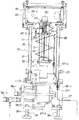
図1を参照して、本形態における極低温冷却装置は、第1段、第2段の冷凍ステージ11、12を持つ冷凍ステージ10を真空容器20内に配置して成る。真空容器20内であって第1段の冷凍ステージ11におけるヘッド部11−1には、そのフランジ部を利用して第2段の冷凍ステージ12を包囲して熱的にシールドするための円筒状の第1の熱シールド板31が設けられている。ここでは、第1の熱シールド板31には銅を用いているが、この限りではない。
【0009】
第2段の冷凍ステージ12におけるヘッド部12−1には、サーマルダンパ40を介して被冷却部、ここでは赤外線センサを搭載するためのマウント部50が設けられている。
【0010】
本形態においては、真空容器20内に更に、第2段の冷凍ステージ12の全体と、第1段の冷凍ステージ11の一部(上部域)と、サーマルダンパ40の大部分とを包囲するように円筒状の第2の熱シールド板32を設けたことを特徴とする。特に、第2の熱シールド板32は、これまでの熱シールド板とは異なった考え方に基づいて設けられている。すなわち、これまでの熱シールド板は、これを積極的に冷却するために、冷凍機の低温部に接続するように設けられるのが普通であった。しかしながら、本形態では第2の熱シールド板32を冷凍ステージの常温部に接続するようにしている。具体的には、第1段の冷凍ステージ11の底部フランジ11−2にリング状のフランジ11−3が取り付けられ、このフランジ11−3にはFRPによるサポート部材33が複数個、周方向に間隔をおいて立設されている。そして、これら複数のサポート部材33の上部に円筒状の第2の熱シールド板32の下部がボルト、ナットにより固定されるようになっている。なお、第2の熱シールド板32は、本形態では銅製のものが使用され、表面には光沢ニッケルメッキが施されている。第2の熱シールド板32は、真空容器20から5mm以上離して設けられる。
【0011】
真空容器20は、第2の熱シールド板32を包囲している円筒状部分21と、この円筒状部分21の上端に連結固定されてマウント部50を包囲している天板付きの筒状部分22とから成る。ここでは、円筒状部分21の材料にはSUS304が用いられ、筒状部分22にはアルミニウム合金板が用いられている。筒状部分22は、円筒状部分21よりも大きな径を有し、ここでは八角形状にされている。真空容器20は、円筒状部分21の下部がフランジ11−3に固定されている。真空容器20は、排気口23を通して真空引きが行われるので、気密性を保持する必要がある。このために、フランジ11−3と円筒状部分21との間の連結固定部、円筒状部分21と筒状部分22との間の連結固定部、筒状部分における天板の接続部にはO−リングによるシール部材が設けられている。
【0012】
また、本形態ではマウント部50には赤外線センサがマウントされるので、筒状部分22には、その複数箇所に赤外線を透過する特別な窓が気密を保持できる状態で設けられる。
【0013】
第2段の冷凍ステージ12のヘッド部12−1に対応する高さ位置で、第1の熱シールド板31の上端部にも、サーマルダンパ40及びマウント部50を包囲している天板付きの筒状の第1のシールド容器34が連結固定されている。この第1のシールド容器34も銅製で、第1の熱シールド板31と同径でサーマルダンパ40を包囲している円筒状部分34−1と、これより大径の筒状部分34−2とから成る。筒状部分34−2において筒状部分22に設けられた窓に対応する箇所にも窓が設けられる。
【0014】
同様にして、サーマルダンパ40の上部に対応する高さ位置で、第2の熱シールド板32の上端部にも、第1のシールド容器34を包囲するように天板付きの筒状の第2のシールド容器35が連結固定されている。勿論、第2のシールド容器35は、第2の熱シールド板32より大きな径を持つ。
【0015】
第1段の冷凍ステージ11の外底部、すなわち真空容器20の外底部には、冷凍ステージ10への冷媒の導出入部36が設けられている。導出入部36には冷媒の導入配管36−1と導出配管36−2が接続され、これらは図示しない冷媒圧縮機に接続されている。
【0016】
フランジ11−3には、複数(ここでは3本)の丸棒による支柱37−1と板体37−2とから成る支持枠体37を介して複数の台座38が設けられている。台座38はねじ部38−1を有し、このねじ部38−1が板体37−2のねじ穴に螺入されると共に、ナット38−2で締め付けされることで高さが調整可能にされている。また、台座38の底部にはゴム板が張られている。
【0017】
更に、必要に応じて、第2の熱シールド板32の外面側には、複層の可撓性熱シールド材から成る熱シールド部材39が巻かれる。
【0018】
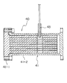
サーマルダンパ40は、図2に示されるように、密閉容器41の内部に複数のフィン状部材42が内蔵され、密閉容器41にはヘリウムガス等の冷媒が導入可能にされている。密閉容器41は、削り出しにより複数のフィン状部材42が一体形成されているフィン側部材41−1と、複数のフィン状部材42を収容する筒状部材を持つ容器側部材41−2とから成り、ボルトにより連結固定されている。この連結固定部にもOリングによるシール部材が設けられる。容器側部材41−2にはヘリウムガス導入用のSUSによる配管43が連結されている。配管43はキャピラリチューブとも呼ばれ、一例をあげると、外径1.59mmである。
【0019】
本形態の極低温冷却装置においては、第1段の冷凍ステージ11により40K程度までの冷却が実現され、第2段の冷凍ステージ12により4Kまでの冷却が実現される。そして、サーマルダンパ40は、この4Kを安定に維持することができる。これは以下の理由による。
【0020】
第2の熱シールド板32は、200K程度の輻射シールド板として作用し、第1の熱シールド板31は、40K程度の輻射シールド板として作用する。すなわち、240K程度の常温部フランジ11−3においてサポートされた第2の熱シールド板32は、40Kの第1の熱シールド板31からの輻射冷却によって冷却されることにより200K程度の輻射シールド板として作用し、第2の熱シールド板32が無い場合と比較した時に、40Kの第1の熱シールド板31に入る輻射熱量が1/4程度に軽減される。これにより、第1の熱シールド板31に侵入する輻射熱に起因するサーマルダンパ40における温度上昇が抑止され、サーマルダンパ40及びマウント部50における冷却温度を安定に4Kに維持することができる。
【0021】
本形態では、サーマルダンパ40への熱侵入を最小限するための工夫もなされている。サーマルダンパ40は、マウント部50における温度上昇を抑制するためのものであるが、冷凍ステージ10側の輻射熱の侵入による温度上昇に加えて、配管43を通しての熱伝導による熱侵入、配管43内のヘリウムガスの対流、サーマルオシレーションと呼ばれる現象による温度上昇の影響も受ける。これは、配管43を通してのヘリウムガスの導入が冷凍機の低圧ラインからの分岐により行われるからである。すなわち、真空容器20内の途中までは配管43内のヘリウムガスは常温に近い温度を持っている。これに対し、真空容器20の底部を通して配管43を真空容器20内に導入し、第1の熱シールド板31の外周に巻き付ける等の方法で接触させてからサーマルダンパ40に導入するというような単純な方法では、サーマルダンパ40の温度を所望の値に維持することは難しかった。
【0022】
このような理由で、配管43を通してのサーマルダンパ40への熱侵入による温度上昇を抑制すべく、以下のような配管43の施工を行っている。
【0023】
図1において、フランジ11−3を通して配管43を真空容器20内に導入し、一旦、第2段の冷凍ステージ12のヘッド部近傍まで立ち上げる。真空容器20内部での入り口部分を位置F(第1の部位)とし、上記の立ち上げ部分を位置E(第2の部位)とする。立ち上げた配管43を第1の熱シールド板31とは離間させた状態でその周囲を螺旋状かつ第1の熱シールド板31の下部側に向かって数回だけ周回するように配設する。
【0024】
次に、第1の熱シールド板31の下部にて配管43を接触させた状態でそのまま立ち上げ、第1の熱シールド板31の上部にて離し、第2段の冷凍ステージ12のヘッド部を迂回させて更に円筒状部分34−1に接触させた状態で立ち上げ、円筒状部分34−1の上部において離す。第1の熱シールド板31の下部側部分を位置D(第3の部位)とし、円筒状部分34−1の上部から離れた部分を位置C(第4の部位)とする。
【0025】
更に、位置Cから下側、すなわち第1の熱シールド板31の上部側に向かって円筒状部分34−1及び第1の熱シールド板31の外周を約半周分周回させてから再び立ち上げてサーマルダンパ40に接続するようにしている。配管43の再立ち上げ部分を位置B(第5の部位)とし、サーマルダンパ40への接続部分を位置Aとする。43−1、43−2、43−3はそれぞれコネクタであり、真空容器20への導入部、及び真空容器20に導入されてからサーマルダンパ40に接続されるまでの配管を複数の分割部品で構成し、あらかじめ成形された部品として作っておくことで、上記のような特殊な配管引き回しを容易にしている。
【0026】
なお、配管43と第1の熱シールド板31との接触、及び配管43と円筒状部分34−1との接触部は、サーマルアンカーとして作用し、いずれもハンダ付けにより固定され、この固定部は箔状のテープでカバーされる。
【0027】
上記のような配管43の引き回しを行うことで、熱伝導による熱侵入は勿論のこと、ヘリウムガスの対流による熱侵入、サーマルオシレーションによる熱侵入を抑制して、サーマルダンパ40における温度上昇を抑制することができた。因みに、位置F、Eでのヘリウムガス温度は300K、位置D、Cでは60K、位置B、Aでは4Kが測定結果として得られている。
【0028】
上記の形態では冷凍ステージとして、第1段、第2段の冷凍ステージを持つ場合について説明したが、本発明は冷凍ステージの段数が3段以上でも適用可能である。この場合、少なくとも最終段の冷凍ステージを包囲するように第1の熱シールド板を設け、第1段の冷凍ステージの底部フランジから第2の熱シールド板を延ばして少なくとも第1の熱シールド板を包囲するように設ければ良い。
【0029】
【発明の効果】
以上説明したように、本発明による極低温冷却装置は、筒状の第1の熱シールド板の周囲に更に、これを囲むように筒状の第2の熱シールド板を設け、しかもこの第2の熱シールド板の下部側を第1段の冷凍ステージにおける底部の常温部に接続するようにしたことにより、真空容器内の熱輻射に起因するマウント部の温度上昇を抑制して、所望の冷却温度、例えば4Kを得ることができる。その結果、マウント部にセンサが搭載される場合にはその検出精度を向上させることができる。
【図面の簡単な説明】
【図1】本発明による極低温冷却装置の縦断面図である。
【図2】図1に示されたサーマルダンパの断面図である。
【符号の説明】
10 冷凍ステージ
11 第1段の冷凍ステージ
12 第2段の冷凍ステージ
20 真空容器
31 第1の熱シールド板
32 第2の熱シールド板
33 サポート部材
36 冷媒の導出入部
37 支持枠体
38 台座
39 熱シールド部材
40 サーマルダンパ
43 配管
50 被冷却部のマウント部[0001]
BACKGROUND OF THE INVENTION
The present invention relates to a cryogenic cooling apparatus equipped with a refrigeration stage of a refrigerator such as a GM refrigerator, and particularly to a cryogenic cooling apparatus suitable for cooling a sensor at an extremely low temperature in order to obtain high detection accuracy.
[0002]
[Prior art]
A superconducting sensor is known as an example of a sensor that requires high stability in detection operation. Superconducting sensors are required to perform detection operations with high accuracy even in an environment where a large temperature difference occurs. For this reason, such a sensor is used in a cooling state at a constant temperature of about 4K in absolute temperature. In order to create such a cooling state, a refrigeration stage of a refrigerator such as a GM refrigerator is accommodated in a vacuum vessel and used. The GM refrigerator has a plurality of refrigeration stages, and can create a cooling state of about several K in a sensor mount portion mounted on the final refrigeration stage.
[0003]
[Problems to be solved by the invention]
However, since such a refrigerator is affected by radiant heat from the outside, a cylindrical heat shield plate is provided around the refrigeration stage in order to suppress radiant heat. Until now, this heat shield plate is usually connected to a low temperature part in a refrigerator and actively cooled.
[0004]
However, even if such a heat shield plate is used, the influence of the radiant heat cannot be completely eliminated, and the sensor mount cannot be cooled to a desired cooling temperature, for example, 4K. This cause is thought to be due to a convection phenomenon in the vacuum vessel. On the other hand, since the superconducting sensor is required to be cooled to 4K as described above, an improvement is required to stably maintain a cryogenic state of about 4K without being affected by radiant heat. ing.
[0005]
It is an object of the present invention to provide a cryogenic cooling device that can satisfy such requirements.
[0006]
[Means for Solving the Problems]
According to the present invention, a plurality of refrigeration stages are arranged in a vacuum vessel, and the head portion of the refrigeration stage at least one stage before the final stage is enclosed in the vacuum vessel and surrounds the final refrigeration stage. In the cryogenic cooling apparatus provided with a cylindrical first heat shield plate for shielding to the inside of the vacuum vessel, a support member provided on a bottom flange of the first stage refrigeration stage is further provided in the vacuum vessel. A cylindrical second heat shield plate is provided so as to surround at least the first heat shield plate, and the second heat shield plate is cooled by radiation cooling from the first heat shield plate. Thus, the amount of radiant heat entering the first heat shield plate is reduced .
[0007]
In particular, the second heat shield plate is made of copper and is subjected to bright nickel plating.
[0008]
DETAILED DESCRIPTION OF THE INVENTION
Referring to FIG. 1, the cryogenic cooling device in this embodiment is configured by disposing a
[0009]
The head portion 12-1 in the second stage refrigeration stage 12 is provided with a
[0010]
In the present embodiment, the
[0011]
The
[0012]
In this embodiment, since the infrared sensor is mounted on the
[0013]
At the height position corresponding to the head portion 12-1 of the second-stage refrigeration stage 12, the upper end portion of the first heat shield plate 31 is also provided with a top plate surrounding the
[0014]
Similarly, at the height position corresponding to the upper part of the
[0015]
A refrigerant lead-in / out
[0016]
The flange 11-3 is provided with a plurality of
[0017]
Further, a
[0018]
As shown in FIG. 2, the
[0019]
In the cryogenic cooling device of the present embodiment, cooling to about 40K is realized by the first
[0020]
The second
[0021]
In this embodiment, a device for minimizing heat intrusion into the
[0022]
For this reason, the following
[0023]
In FIG. 1, a
[0024]
Next, the
[0025]
Further, the cylindrical portion 34-1 and the outer periphery of the first heat shield plate 31 are rotated by about a half turn from the position C to the lower side, that is, toward the upper side of the first heat shield plate 31, and then restarted. The
[0026]
Note that the contact between the
[0027]
By routing the piping 43 as described above, not only heat intrusion due to heat conduction but also heat intrusion due to convection of helium gas and heat invasion due to thermal oscillation are suppressed, and temperature rise in the
[0028]
In the above embodiment, the case where the first and second refrigeration stages are provided as the refrigeration stages has been described. However, the present invention can be applied even when the number of refrigeration stages is three or more. In this case, a first heat shield plate is provided so as to surround at least the final stage refrigeration stage, and the second heat shield plate is extended from the bottom flange of the first stage refrigeration stage to provide at least the first heat shield plate. What is necessary is just to provide so that it may surround.
[0029]
【The invention's effect】
As described above, the cryogenic cooling device according to the present invention is further provided with the cylindrical second heat shield plate around the cylindrical first heat shield plate so as to surround the second heat shield plate . By connecting the lower part of the heat shield plate to the room temperature part at the bottom of the first refrigeration stage, the temperature rise of the mount part due to heat radiation in the vacuum vessel is suppressed, and desired cooling is achieved. A temperature, for example 4K, can be obtained. As a result, when a sensor is mounted on the mount portion, the detection accuracy can be improved.
[Brief description of the drawings]
FIG. 1 is a longitudinal sectional view of a cryogenic cooling device according to the present invention.
FIG. 2 is a cross-sectional view of the thermal damper shown in FIG.
[Explanation of symbols]
DESCRIPTION OF
Claims (8)
前記真空容器内には更に、第1段の冷凍ステージの底部フランジに設けられたサポート部材を介して少なくとも前記第1の熱シールド板を包囲するように筒状の第2の熱シールド板を設け、該第2の熱シールド板を前記第1の熱シールド板からの輻射冷却によって冷却する構成としたことにより、前記第1の熱シールド板に入る輻射熱量を軽減したことを特徴とする極低温冷却装置。A plurality of refrigeration stages with the cryogenic side as the final stage are arranged in a vacuum vessel, and the head portion of the refrigeration stage at least one stage before the final stage is enclosed in the vacuum vessel and surrounds the final refrigeration stage. In the cryogenic cooling device provided with a cylindrical first heat shield plate for thermally shielding,
A cylindrical second heat shield plate is further provided in the vacuum vessel so as to surround at least the first heat shield plate via a support member provided on the bottom flange of the first refrigeration stage. by the second heat shield plate has a structure cooled by radiation cooling from the first heat shield plate, characterized in that to reduce the radiation heat quantity entering the first heat shield plate electrode Low temperature cooling device.
Priority Applications (1)
| Application Number | Priority Date | Filing Date | Title |
|---|---|---|---|
| JP2001113567A JP3845708B2 (en) | 2001-04-12 | 2001-04-12 | Cryogenic cooling device |
Applications Claiming Priority (1)
| Application Number | Priority Date | Filing Date | Title |
|---|---|---|---|
| JP2001113567A JP3845708B2 (en) | 2001-04-12 | 2001-04-12 | Cryogenic cooling device |
Publications (2)
| Publication Number | Publication Date |
|---|---|
| JP2002310521A JP2002310521A (en) | 2002-10-23 |
| JP3845708B2 true JP3845708B2 (en) | 2006-11-15 |
Family
ID=18964769
Family Applications (1)
| Application Number | Title | Priority Date | Filing Date |
|---|---|---|---|
| JP2001113567A Expired - Fee Related JP3845708B2 (en) | 2001-04-12 | 2001-04-12 | Cryogenic cooling device |
Country Status (1)
| Country | Link |
|---|---|
| JP (1) | JP3845708B2 (en) |
Families Citing this family (1)
| Publication number | Priority date | Publication date | Assignee | Title |
|---|---|---|---|---|
| JP7585627B2 (en) * | 2020-06-15 | 2024-11-19 | 富士電機株式会社 | Heat Transfer Equipment |
-
2001
- 2001-04-12 JP JP2001113567A patent/JP3845708B2/en not_active Expired - Fee Related
Also Published As
| Publication number | Publication date |
|---|---|
| JP2002310521A (en) | 2002-10-23 |
Similar Documents
| Publication | Publication Date | Title |
|---|---|---|
| JPH0629635Y2 (en) | Cryostat | |
| US4526015A (en) | Support for cryostat penetration tube | |
| JP2008111666A (en) | Cryogenic cooler | |
| JPH0828535B2 (en) | Superconducting magnet | |
| JP2006046896A (en) | Lossless cryogen cooling device for cryostat configuration | |
| CN110504078A (en) | Cryogenic cooling unit | |
| US5884489A (en) | Superconducting magnets | |
| JP3845708B2 (en) | Cryogenic cooling device | |
| US20120306492A1 (en) | Penetration tube assemblies for reducing cryostat heat load | |
| JP3845672B2 (en) | Cryogenic cooling device | |
| JP2014052133A (en) | Bayonet coupler for cryogenic fluid | |
| JP4892328B2 (en) | Refrigerator with magnetic shield | |
| CN102809240A (en) | Penetration tube assemblies for reducing cryostat heat load | |
| JP6588264B2 (en) | Cryogenic refrigerant supply system | |
| EP0253883B1 (en) | Cryogenically cooled radiation detection apparatus | |
| JP2010003943A (en) | Heat insulating support and superconducting apparatus equipped with the heat insulating support | |
| JPH0640341Y2 (en) | Seismic bellows for vacuum members | |
| US20080271467A1 (en) | Refrigerator Interface for Cryostat | |
| Krysanov et al. | A Helium Cryostat for Investigating the Properties of Massive Solid Resonators with Deep Cooling | |
| RU2194254C1 (en) | Device for receiving ultraviolet radiation | |
| CN121114078B (en) | Resonant cavity low-temperature system and testing method thereof | |
| US20050156595A1 (en) | Magnetic resonance imaging apparatus with reduced noise production | |
| KR102354603B1 (en) | Medical superconducting magnet | |
| JP2008267635A (en) | Cryogenic cooling device and cryogenic cooling method | |
| US7482808B2 (en) | Superconductive magnet apparatus and magnetic resonance imaging apparatus |
Legal Events
| Date | Code | Title | Description |
|---|---|---|---|
| A977 | Report on retrieval |
Free format text: JAPANESE INTERMEDIATE CODE: A971007 Effective date: 20050401 |
|
| A131 | Notification of reasons for refusal |
Free format text: JAPANESE INTERMEDIATE CODE: A131 Effective date: 20050921 |
|
| A711 | Notification of change in applicant |
Free format text: JAPANESE INTERMEDIATE CODE: A712 Effective date: 20051109 |
|
| A521 | Written amendment |
Free format text: JAPANESE INTERMEDIATE CODE: A523 Effective date: 20051110 |
|
| A521 | Written amendment |
Free format text: JAPANESE INTERMEDIATE CODE: A821 Effective date: 20051109 |
|
| TRDD | Decision of grant or rejection written | ||
| A01 | Written decision to grant a patent or to grant a registration (utility model) |
Free format text: JAPANESE INTERMEDIATE CODE: A01 Effective date: 20060628 |
|
| A61 | First payment of annual fees (during grant procedure) |
Free format text: JAPANESE INTERMEDIATE CODE: A61 Effective date: 20060726 |
|
| R150 | Certificate of patent or registration of utility model |
Free format text: JAPANESE INTERMEDIATE CODE: R150 |
|
| R154 | Certificate of patent or utility model (reissue) |
Free format text: JAPANESE INTERMEDIATE CODE: R154 |
|
| R150 | Certificate of patent or registration of utility model |
Free format text: JAPANESE INTERMEDIATE CODE: R150 |
|
| FPAY | Renewal fee payment (event date is renewal date of database) |
Free format text: PAYMENT UNTIL: 20090901 Year of fee payment: 3 |
|
| S531 | Written request for registration of change of domicile |
Free format text: JAPANESE INTERMEDIATE CODE: R313531 |
|
| FPAY | Renewal fee payment (event date is renewal date of database) |
Free format text: PAYMENT UNTIL: 20090901 Year of fee payment: 3 |
|
| R350 | Written notification of registration of transfer |
Free format text: JAPANESE INTERMEDIATE CODE: R350 |
|
| FPAY | Renewal fee payment (event date is renewal date of database) |
Free format text: PAYMENT UNTIL: 20090901 Year of fee payment: 3 |
|
| FPAY | Renewal fee payment (event date is renewal date of database) |
Free format text: PAYMENT UNTIL: 20100901 Year of fee payment: 4 |
|
| FPAY | Renewal fee payment (event date is renewal date of database) |
Free format text: PAYMENT UNTIL: 20110901 Year of fee payment: 5 |
|
| FPAY | Renewal fee payment (event date is renewal date of database) |
Free format text: PAYMENT UNTIL: 20120901 Year of fee payment: 6 |
|
| FPAY | Renewal fee payment (event date is renewal date of database) |
Free format text: PAYMENT UNTIL: 20120901 Year of fee payment: 6 |
|
| FPAY | Renewal fee payment (event date is renewal date of database) |
Free format text: PAYMENT UNTIL: 20130901 Year of fee payment: 7 |
|
| R250 | Receipt of annual fees |
Free format text: JAPANESE INTERMEDIATE CODE: R250 |
|
| R250 | Receipt of annual fees |
Free format text: JAPANESE INTERMEDIATE CODE: R250 |
|
| S533 | Written request for registration of change of name |
Free format text: JAPANESE INTERMEDIATE CODE: R313533 |
|
| R350 | Written notification of registration of transfer |
Free format text: JAPANESE INTERMEDIATE CODE: R350 |
|
| R250 | Receipt of annual fees |
Free format text: JAPANESE INTERMEDIATE CODE: R250 |
|
| R250 | Receipt of annual fees |
Free format text: JAPANESE INTERMEDIATE CODE: R250 |
|
| LAPS | Cancellation because of no payment of annual fees |