JP3843785B2 - Fingerprint authentication device - Google Patents
Fingerprint authentication device Download PDFInfo
- Publication number
- JP3843785B2 JP3843785B2 JP2001258250A JP2001258250A JP3843785B2 JP 3843785 B2 JP3843785 B2 JP 3843785B2 JP 2001258250 A JP2001258250 A JP 2001258250A JP 2001258250 A JP2001258250 A JP 2001258250A JP 3843785 B2 JP3843785 B2 JP 3843785B2
- Authority
- JP
- Japan
- Prior art keywords
- rotation
- fingerprint
- cylinder
- fingerprint authentication
- authentication device
- Prior art date
- Legal status (The legal status is an assumption and is not a legal conclusion. Google has not performed a legal analysis and makes no representation as to the accuracy of the status listed.)
- Expired - Fee Related
Links
Images


Classifications
-
- G—PHYSICS
- G06—COMPUTING; CALCULATING OR COUNTING
- G06V—IMAGE OR VIDEO RECOGNITION OR UNDERSTANDING
- G06V40/00—Recognition of biometric, human-related or animal-related patterns in image or video data
- G06V40/10—Human or animal bodies, e.g. vehicle occupants or pedestrians; Body parts, e.g. hands
- G06V40/12—Fingerprints or palmprints
- G06V40/13—Sensors therefor
- G06V40/1329—Protecting the fingerprint sensor against damage caused by the finger
-
- G—PHYSICS
- G06—COMPUTING; CALCULATING OR COUNTING
- G06F—ELECTRIC DIGITAL DATA PROCESSING
- G06F18/00—Pattern recognition
Description
【0001】
【発明の属する技術分野】
本発明は指紋認証装置に関し、特に指紋センサの保護シャッターを取りつける必要がない指紋認証装置に関する。
【0002】
【従来の技術】
これまでの指紋認証装置で使われている、指紋の画像を取得するセンサ(以下、指紋センサと称す)は、図8に示すように、取得したい指紋画像の大きさと同じ大きさを考えた2センチ四方程度の2次元平面であることが多かった。この2次元平面の指紋センサ1は、センサの表面積が大きいことから、センサ表面の傷つけや汚損をしてしまう可能性が高く、またセンサ面に直接指が触れるため静電気による指紋センサそのものの破壊が起こりやすいという問題を持っている。そのため、例えば実開平4−4352公報に見られるような往復開閉自由に配備された指紋センサの保護シャッターや、図9に示すように指紋センサ3に対し回転自由に配備された保護シャッター4を設ける装置も考案されている。しかし、指紋センサの保護シャッターを設ける方法は、指紋認証を行うたびに指紋センサの保護シャッターを開けなければならず、操作性の低下を引き起こしていた。これを解決するため、図10に示すようなリニア式指紋センサが考案された。これは細長い指紋センサ2の上を、指を滑らせることで指全体の指紋を取得するという方式の指紋センサである。これを用いればセンサ表面の保護シャッターの必要性が低減する。しかしいくら低減したとはいえ、依然としてセンサ表面への傷つきや汚損、静電気による破壊の可能性を持っていることに変わりなく、保護シャッターを取りつける必要が完全になくなるわけではなかった。
【0003】
【発明が解決しようとする課題】
上述したように、これまでの指紋認証装置で使われている指紋センサは、最新式のリニア式指紋センサであっても、操作性の低下を引き起こす保護シャッターをつけない限り、センサ表面への傷つきや汚損、静電気による破壊の可能性を持っていた。
【0004】
そこで本発明では、操作性の低下を引き起こす保護シャッターを不要としながらも、指紋センサの傷つきや汚損、静電気破壊を防ぐことが出来る指紋認証装置を提案する。
【0005】
【課題を解決するための手段】
本願の第1の発明は、指紋認証装置であって、
指紋を認証しない際には、前記指紋認証装置内に隠れる第1の位置に保持され、指紋を認証する際には、指紋を認証される指の単一的な動作により、前記第1の位置から、前記指の指紋をセンス可能な位置であるとともに、前記指紋認証装置外に露出する第2の位置に移動される指紋センサと、
前記第1の位置を調整するための調整手段とを備えたことを特徴とする。
【0006】
本願の第2の発明は、指紋認証装置であって、
指紋を認証しない際には、前記指紋認証装置内に隠れる第1の位置に保持され、指紋を認証する際には、指紋を認証される指の動作により、前記第1の位置から、前記指の指紋をセンス可能な位置であるとともに、前記指紋認証装置外に露出する第2の位置に移動され、前記移動中に前記指の少なくとも一部に接触され、前記指の少なくとも一部が接触されたまま前記第2の位置に移動される指紋センサと、
前記第1の位置を調整するための調整手段とを備えたことを特徴とする。
【0007】
本願の第3の発明は、指紋認証装置において、
指紋センサを格納し、動力によって一定方向に回転軸を中心に回転し、前記回転軸に突起を有するシリンダを含み、
前記シリンダの前記回転軸の突起は前記動力によって一定方向に回転した時、前記シリンダの隣にあって前記シリンダとは独立して前記指紋認証装置内に存在する回転角調整ダイヤルに取り付けられた突起と衝突することよって前記回転が停止し、
前記回転角調整ダイヤルを外部から操作することで前記シリンダの回転停止位置を任意に調整できることが出来ることを特徴とする。
【0008】
本願の第4の発明は、第3の発明の前記シリンダが前記動力によって回転し前記回転角調整ダイヤルに取り付けられた突起と衝突することよって前記回転が停止した時、前記指紋センサが前記指紋認証装置の内部に隠蔽されることを特徴とする。
【0009】
本願の第5の発明は、第3の発明の前記シリンダは外部からの操作により前記動力による回転と逆方向に回転させたとき、前記シリンダの前記回転軸の突起が前記指紋認証装置本体に予め固定して取りつけられている回転停止棒と衝突することよって前記逆方向の回転が停止することを特徴とする。
【0010】
本願の第6の発明は、第5の発明の前記シリンダの前記外部からの操作による前記逆方向の回転が前記回転停止棒によって停止した時前記指紋センサが前記指紋認証装置の外部に露出することを特徴とする。
【0011】
本願の第7の発明は、第5及び第6の発明の前記外部からの操作が認証させたい指の指先によることを特徴とする。
【0012】
本願の第8の発明は、第3の発明の前記シリンダが前記指紋認証装置の角に設置されていることを特徴とする。
【0014】
「作用」
本発明は、保護シャッターを不要としながら指紋センサを傷つきや汚損、静電気破壊から守れる事と、1つの動作だけで指紋センサに指を置くことができる事と、その置いた指の位置が指紋センサに対し適当な位置となる事と、ユーザの好みや指の長短に対して柔軟に対応できる点を特徴とする。従来の一般的な指紋認証装置の指紋センサは、動かないように固定して組込まれており、保護シャッター部分が動くことにより指紋センサが外部に露出する構造となっている。たとえば図9の指紋認証装置を用いて説明すると、指紋センサ3が固定されており、保護シャッター4が動くような構造となっている。これに対し、指紋センサを回転する構造として保護シャッターを不要とすることで、未使用時に指紋センサが指紋認証装置内部に隠され、その結果として傷つきや汚損、静電気破壊から守られる。また指紋センサを指先で回転させて露出させ、そのまま現れた指紋センサに指を置くことができるため、1つの動作で指紋認証装置を使うことができ、高い操作性を実現できる。また指紋センサの回転角度量をユーザの好みや指の長短に合わせて変化させることで、指紋センサに置いた指の位置がセンサ面の中央になり、常に指紋センサ面に対して適当な位置に指が置かれるようになる。
【0015】
【発明の実施の形態】
次に、本発明の実施の形態について図面を参照して詳細に説明する。
【0016】
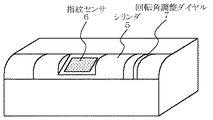
図1は、本発明の指紋認証装置の外観図である。シリンダ5には、指紋センサ6が設置されている。また回転角調整ダイヤル7が設置されている。
【0017】
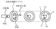
図2は、指紋認証装置の内部構造を示す図である。指紋センサ6を格納するシリンダ5は、回転軸8を中心に回転する。また回転軸8には、動力源のゼンマイ12と、突起9がある。回転軸8と同じ回転軸上には、突起10の付いた回転角調整ダイヤル7がある。また、回転停止棒11は、指紋認証装置本体に固定して取りつけられている。指紋センサで取得されたデータは、ケーブル13を介して指紋認証装置内部の情報処理装置に出力される。
【0018】
次に、本発明の実施の形態の動作について図面を参照して説明する。指紋認証装置が使われていない場合は、図3のように、指紋センサ6が指紋認証装置の中に隠れるように停止している。シリンダ5は、回転軸8に取りつけられたゼンマイ12の回転力により、図3を正面に見て手前方向に回転しようとする。しかしある一定以上回転すると、図4に示すように、回転軸8に取りつけられた突起9と、回転角調整ダイヤル7に取りつけられた突起10が衝突するため、シリンダ5の回転は停止する。すなわち回転角調整ダイヤル7を操作することで、シリンダ5の回転停止位置を調整できる。
【0019】
図5のように認証させたい指の指先を使い、図3を正面に見て奥行き方向にシリンダ5を回転させる力を加えると、その力がゼンマイ12による手前方向の回転力以上となった時、図6のように奥行き方向に回転を始める。すると図1のように、指紋認証装置の中に隠れていた指紋センサ6が露出する。ある一定以上回転すると、回転軸8に取りつけられた突起9と、指紋認証装置本体に固定して取りつけられた回転停止棒11とが衝突するため、シリンダ5の回転は停止する(図4参照)。その回転停止位置は、図1のように指紋センサ6が外部に露出する位置となっている。その時、指の位置は、図7のように指紋センサの中央付近に指紋の渦の中心付近が位置するようになっている。指の位置が指紋センサの中央付近からずれる場合には、回転角調整ダイヤル7を回すことで調整する。シリンダ5を押さえていた指を離すとシリンダ5は、ゼンマイ12の回転力により手前方向への回転を始め、突起9と突起10がぶつかる位置で停止し、初期状態の図3に戻る。
【0020】
尚、上述の実施例では、動力源としてゼンマイを用いたが、同様な回転力を生じる物であれば、これに固定されるものではなく、例えば、バネ、モーター、あるいはゴム、おもりなどであっても良い。
【0021】
「発明の他の実施の形態」
1:上記実施例では、回転方向が奥行き方向となっているが、逆方向である手前方向に回転するような構造とすることも可能である。
2: 上記実施例では、設置場所が指紋認証装置の角となっているが、平たんな部分に設置する構造とすることも可能である。
3:図3のシリンダ5や回転角調整ダイヤル7に滑り止めの構造(凹凸や滑り止め材料、レバーなど)を設置することで、より操作性を向上させることも可能である。
4:上記実施例では、回転角調整ダイヤルを設置しているが、これを無くして回転量をあらかじめ固定し、構造を単純にすることで小型化することも可能である。
5:上記実施例では、指紋センサが2次元の平面センサを使っているように描かれているが、これがリニア式指紋センサなど、他の方式、形状のものであってもよい。
【0022】
【発明の効果】
以上説明したように、本発明により、以下の効果がある。
【0023】
効果1:指紋センサ自身が回転して指紋認証装置内に隠れることで、センサの保護シャッターを不要としながらも、指紋センサの保護が可能となる。
【0024】
効果2:指紋センサ自身が回転することで、従来二つの動作が必要だったところが、指を押し上げるという一つの動作だけで指を指紋センサに載せることが可能となり、操作性が向上する。
【0025】
効果3:指紋センサの回転量と同じ長さだけ指が移動するため、常に一定した指の移動量となる。このため指紋センサに対して指の置かれる位置が一定となり、安定した指紋認証が可能となる。
【0026】
効果4:ダイヤルを調整することで、指紋センサの回転量を変えられるため、ユーザの好みや指の長短に対し柔軟に対応することができる。
【図面の簡単な説明】
【図1】本発明の指紋認証装置の指紋センサ露出時の外観図である。
【図2】図1の指紋認証装置の内部構造を示す図である。
【図3】本発明の指紋認証装置の指紋センサ格納時の外観図である。
【図4】図2の動作説明図である。
【図5】本発明の動作説明図である。
【図6】本発明の動作説明図である。
【図7】本発明の動作説明図である。
【図8】従来の指紋センサの外観図である。
【図9】従来の保護シャッター付き指紋センサの外観図である。
【図10】従来のリニア式指紋センサの外観図である。
【符号の説明】
1 指紋センサ
2 細長い指紋センサ
3 指紋センサ
4 保護シャッター
5 シリンダ
6 指紋センサ
7 回転角調整ダイヤル
8 回転軸
9 突起
10 突起
11 回転停止棒
12 ゼンマイ
13 ケーブル[0001]
BACKGROUND OF THE INVENTION
The present invention relates to a fingerprint authentication device, and more particularly to a fingerprint authentication device that does not require a protective shutter for a fingerprint sensor.
[0002]
[Prior art]
As shown in FIG. 8, a sensor for acquiring a fingerprint image (hereinafter referred to as a fingerprint sensor) used in a conventional fingerprint authentication apparatus has the same size as the fingerprint image to be acquired. It was often a two-dimensional plane about a centimeter square. The two-dimensional
[0003]
[Problems to be solved by the invention]
As described above, even if the fingerprint sensor used in previous fingerprint authentication devices is the latest linear fingerprint sensor, the sensor surface will be damaged unless a protective shutter is attached that causes a decrease in operability. There was a possibility of destruction due to pollution, static electricity.
[0004]
Therefore, the present invention proposes a fingerprint authentication device that can prevent the fingerprint sensor from being damaged, stained, or electrostatically destroyed while eliminating the need for a protective shutter that causes a decrease in operability.
[0005]
[Means for Solving the Problems]
1st invention of this application is a fingerprint authentication apparatus , Comprising:
When the fingerprint is not authenticated, the fingerprint is held in the first position hidden in the fingerprint authentication device. When the fingerprint is authenticated, the first position is obtained by a single operation of the finger for authenticating the fingerprint. A fingerprint sensor which is a position where the fingerprint of the finger can be sensed and is moved to a second position exposed outside the fingerprint authentication device;
And adjusting means for adjusting the first position .
[0006]
A second invention of the present application is a fingerprint authentication device,
When the fingerprint is not authenticated, the fingerprint is held in the first position hidden in the fingerprint authentication apparatus. When the fingerprint is authenticated, the finger is authenticated from the first position by the action of the finger to be authenticated. Is moved to a second position exposed to the outside of the fingerprint authentication device, touched at least part of the finger during the movement, and touched at least part of the finger. A fingerprint sensor that is moved to the second position as it is;
And adjusting means for adjusting the first position .
[0007]
According to a third aspect of the present invention, in the fingerprint authentication device,
Storing a fingerprint sensor, rotating around a rotation axis in a fixed direction by power, and including a cylinder having a protrusion on the rotation axis;
When the projection of the rotation shaft of the cylinder is rotated in a certain direction by the power, the projection is adjacent to the cylinder and is attached to a rotation angle adjustment dial that exists in the fingerprint authentication device independently of the cylinder. The rotation stops by colliding with
The rotation stop position of the cylinder can be arbitrarily adjusted by operating the rotation angle adjustment dial from the outside.
[0008]
According to a fourth invention of the present application, when the cylinder of the third invention is rotated by the power and collides with a protrusion attached to the rotation angle adjustment dial, the rotation of the cylinder is stopped when the rotation is stopped. It is concealed inside the device.
[0009]
According to a fifth invention of the present application, when the cylinder of the third invention is rotated in the direction opposite to the rotation by the power by an operation from the outside, the protrusion of the rotation shaft of the cylinder is previously placed on the fingerprint authentication device main body. The rotation in the reverse direction is stopped by colliding with a rotation stop rod fixedly attached.
[0010]
According to a sixth invention of the present application, the fingerprint sensor is exposed to the outside of the fingerprint authentication device when the reverse rotation due to the external operation of the cylinder of the fifth invention is stopped by the rotation stop rod. It is characterized by.
[0011]
The seventh invention of the present application is characterized in that the external operation of the fifth and sixth inventions is based on a fingertip of a finger to be authenticated.
[0012]
The eighth invention of the present application is characterized in that the cylinder of the third invention is installed at a corner of the fingerprint authentication device.
[0014]
"Action"
The present invention can protect the fingerprint sensor from being damaged, soiled, or electrostatically destroyed while eliminating the need for a protective shutter, can place a finger on the fingerprint sensor with only one operation, and the position of the placed finger is the fingerprint sensor. However, it is characterized by being able to flexibly respond to user's preference and finger length. A conventional fingerprint sensor of a general fingerprint authentication device is fixed and incorporated so as not to move, and has a structure in which the fingerprint sensor is exposed to the outside when the protective shutter portion moves. For example, using the fingerprint authentication device of FIG. 9, the fingerprint sensor 3 is fixed, and the
[0015]
DETAILED DESCRIPTION OF THE INVENTION
Next, embodiments of the present invention will be described in detail with reference to the drawings.
[0016]
FIG. 1 is an external view of a fingerprint authentication device according to the present invention. A
[0017]
FIG. 2 is a diagram showing an internal structure of the fingerprint authentication device. The
[0018]
Next, the operation of the embodiment of the present invention will be described with reference to the drawings. When the fingerprint authentication device is not used, the
[0019]
When using the fingertip of the finger to be authenticated as shown in FIG. 5 and applying a force to rotate the
[0020]
In the above-described embodiments, the mainspring is used as the power source. However, any spring that generates the same rotational force is not fixed to this, and is, for example, a spring, a motor, rubber, a weight, or the like. May be.
[0021]
“Other Embodiments of the Invention”
1: In the above embodiment, the rotation direction is the depth direction, but it is also possible to have a structure in which the rotation direction is the reverse direction.
2: In the above embodiment, the installation place is the corner of the fingerprint authentication device, but it may be installed on a flat part.
3: It is possible to further improve the operability by providing a non-slip structure (unevenness, anti-slip material, lever, etc.) in the
4: In the above embodiment, the rotation angle adjustment dial is installed. However, it is possible to reduce the size by eliminating this and fixing the rotation amount in advance and simplifying the structure.
5: In the above embodiment, the fingerprint sensor is depicted as using a two-dimensional planar sensor, but it may be of other types and shapes, such as a linear fingerprint sensor.
[0022]
【The invention's effect】
As described above, the present invention has the following effects.
[0023]
Effect 1: Since the fingerprint sensor itself rotates and hides in the fingerprint authentication device, the fingerprint sensor can be protected while the sensor shutter is unnecessary.
[0024]
Effect 2: By rotating the fingerprint sensor itself, it is possible to place the finger on the fingerprint sensor by only one operation of pushing up the finger, which has been conventionally required, and the operability is improved.
[0025]
Effect 3: Since the finger moves by the same length as the rotation amount of the fingerprint sensor, the finger movement amount is always constant. For this reason, the position where the finger is placed with respect to the fingerprint sensor is constant, and stable fingerprint authentication is possible.
[0026]
Effect 4: Since the rotation amount of the fingerprint sensor can be changed by adjusting the dial, it is possible to flexibly cope with user preference and finger length.
[Brief description of the drawings]
FIG. 1 is an external view of a fingerprint authentication device of the present invention when a fingerprint sensor is exposed.
FIG. 2 is a diagram showing an internal structure of the fingerprint authentication device of FIG.
FIG. 3 is an external view of the fingerprint authentication device of the present invention when the fingerprint sensor is stored.
4 is an operation explanatory diagram of FIG. 2; FIG.
FIG. 5 is an operation explanatory diagram of the present invention.
FIG. 6 is an operation explanatory diagram of the present invention.
FIG. 7 is an operation explanatory diagram of the present invention.
FIG. 8 is an external view of a conventional fingerprint sensor.
FIG. 9 is an external view of a conventional fingerprint sensor with a protective shutter.
FIG. 10 is an external view of a conventional linear fingerprint sensor.
[Explanation of symbols]
DESCRIPTION OF
Claims (5)
指紋センサを格納し、動力によって一定方向に回転軸を中心に回転し、前記回転軸に突起を有するシリンダを含み、
前記シリンダの前記回転軸の突起は前記動力によって一定方向に回転した時、前記シリンダの隣にあって前記シリンダとは独立して前記指紋認証装置内に存在する回転角調整ダイヤルに取り付けられた突起と衝突することよって前記回転が停止し、
前記回転角調整ダイヤルを外部から操作することで前記シリンダの回転停止位置を任意に調整できることが出来ることを特徴とする指紋認証装置。In the fingerprint authentication device,
Storing a fingerprint sensor, rotating around a rotation axis in a fixed direction by power, and including a cylinder having a protrusion on the rotation axis;
When the projection of the rotation shaft of the cylinder is rotated in a certain direction by the power, the projection is adjacent to the cylinder and is attached to a rotation angle adjustment dial that exists in the fingerprint authentication device independently of the cylinder. The rotation stops by colliding with
A fingerprint authentication apparatus characterized in that the rotation stop position of the cylinder can be arbitrarily adjusted by operating the rotation angle adjustment dial from the outside.
Priority Applications (4)
| Application Number | Priority Date | Filing Date | Title |
|---|---|---|---|
| JP2001258250A JP3843785B2 (en) | 2001-08-28 | 2001-08-28 | Fingerprint authentication device |
| TW091114507A TWI243338B (en) | 2001-08-28 | 2002-07-01 | Fingerprint recognition device |
| CNB021282021A CN100424715C (en) | 2001-08-28 | 2002-08-02 | Finger-print certification device |
| KR10-2002-0050682A KR100462141B1 (en) | 2001-08-28 | 2002-08-27 | Fingerprint approval device |
Applications Claiming Priority (1)
| Application Number | Priority Date | Filing Date | Title |
|---|---|---|---|
| JP2001258250A JP3843785B2 (en) | 2001-08-28 | 2001-08-28 | Fingerprint authentication device |
Publications (2)
| Publication Number | Publication Date |
|---|---|
| JP2003067730A JP2003067730A (en) | 2003-03-07 |
| JP3843785B2 true JP3843785B2 (en) | 2006-11-08 |
Family
ID=19085805
Family Applications (1)
| Application Number | Title | Priority Date | Filing Date |
|---|---|---|---|
| JP2001258250A Expired - Fee Related JP3843785B2 (en) | 2001-08-28 | 2001-08-28 | Fingerprint authentication device |
Country Status (4)
| Country | Link |
|---|---|
| JP (1) | JP3843785B2 (en) |
| KR (1) | KR100462141B1 (en) |
| CN (1) | CN100424715C (en) |
| TW (1) | TWI243338B (en) |
Families Citing this family (8)
| Publication number | Priority date | Publication date | Assignee | Title |
|---|---|---|---|---|
| CN1768315A (en) * | 2003-01-21 | 2006-05-03 | Para3公司 | Externally hung type electronic equipment |
| JP4978486B2 (en) * | 2008-01-30 | 2012-07-18 | セイコーエプソン株式会社 | Image reading apparatus and information processing apparatus |
| JP4484087B2 (en) * | 2008-03-05 | 2010-06-16 | 日本電気株式会社 | Fingerprint machine cleaning device and method |
| US9726275B2 (en) | 2014-12-18 | 2017-08-08 | Sl Corporation | Shift lever of automotive transmission |
| CN106766017A (en) * | 2017-03-14 | 2017-05-31 | 珠海格力电器股份有限公司 | Air-conditioner and its people's induction device |
| CN111677176B (en) * | 2020-06-16 | 2021-06-15 | 嘉兴龙吟光伏材料股份有限公司 | Energy self-sufficient type wisdom photovoltaic integration roof |
| CN112017349B (en) * | 2020-08-28 | 2022-06-14 | 林捷 | Campus terminal unified management system |
| CN114024777B (en) * | 2022-01-05 | 2022-03-25 | 北京顶象技术有限公司 | Method and device for detecting whether fingerprints of equipment collide |
Family Cites Families (8)
| Publication number | Priority date | Publication date | Assignee | Title |
|---|---|---|---|---|
| JPH0488586A (en) * | 1990-08-01 | 1992-03-23 | Sharp Corp | Fingerprint input device |
| JPH04367984A (en) * | 1991-06-17 | 1992-12-21 | Toshiba Corp | Fingerprint signal input device |
| CN2201059Y (en) * | 1994-10-25 | 1995-06-21 | 李虹 | Infrared fingerprint recognizer |
| JPH08263631A (en) * | 1995-03-23 | 1996-10-11 | Nippon Telegr & Teleph Corp <Ntt> | Fingerprint input device |
| JP3097028B2 (en) * | 1996-09-04 | 2000-10-10 | 富士通電装株式会社 | Fingerprint collection device |
| US6324310B1 (en) * | 1998-06-02 | 2001-11-27 | Digital Persona, Inc. | Method and apparatus for scanning a fingerprint using a linear sensor |
| KR100652370B1 (en) * | 2000-06-15 | 2006-11-30 | 삼성전자주식회사 | Semiconductor memory device removing floating body effect and method of fabricating the same |
| KR20020040413A (en) * | 2000-11-24 | 2002-05-30 | 장대훈 | Door Opening/Closing Apparatus Having FingerPrint Sensor |
-
2001
- 2001-08-28 JP JP2001258250A patent/JP3843785B2/en not_active Expired - Fee Related
-
2002
- 2002-07-01 TW TW091114507A patent/TWI243338B/en not_active IP Right Cessation
- 2002-08-02 CN CNB021282021A patent/CN100424715C/en not_active Expired - Fee Related
- 2002-08-27 KR KR10-2002-0050682A patent/KR100462141B1/en not_active IP Right Cessation
Also Published As
| Publication number | Publication date |
|---|---|
| TWI243338B (en) | 2005-11-11 |
| CN100424715C (en) | 2008-10-08 |
| KR100462141B1 (en) | 2004-12-17 |
| KR20030019115A (en) | 2003-03-06 |
| CN1402184A (en) | 2003-03-12 |
| JP2003067730A (en) | 2003-03-07 |
Similar Documents
| Publication | Publication Date | Title |
|---|---|---|
| JP3843785B2 (en) | Fingerprint authentication device | |
| US7706137B2 (en) | Electronic apparatus | |
| US9715251B2 (en) | Portable device | |
| US20080235793A1 (en) | Integrity protection in data processing systems | |
| WO2002019066A3 (en) | Virus protection in an internet environment | |
| US20180074545A1 (en) | Capacitive touch opening display for electronic device | |
| US20120092820A1 (en) | Portable electronic device with slide and tilt mechanism | |
| GB2363669A (en) | Inertial latch for mobile disc drive | |
| US7478247B2 (en) | Methods and systems for securing data processing devices | |
| JP2004310658A (en) | Information appliance | |
| TWI705322B (en) | Foldable electronic device and device protection method | |
| CN203571380U (en) | Stepwise type magnet locating device and camera with same | |
| JP3138662B2 (en) | Keyboard input device | |
| JP2001143052A (en) | Protection cover for fingerprint authentication sensor | |
| JP6055008B2 (en) | Portable information processing apparatus, magnetic disk device protection method, and computer-executable program | |
| JPH0344725A (en) | Input pen device | |
| JP2002070907A (en) | Rotary damper | |
| JPH11257339A (en) | Opening and closing device | |
| TWI790868B (en) | Portable electronic device | |
| US20070140766A1 (en) | Rotatable connection apparatus for fixing position of object to be rotated via friction adjustment | |
| KR100553423B1 (en) | Mobile communication terminal having semi-automatic carkit cover using magnet | |
| GR20210100413A (en) | Mouse pad with specific anchoring positions and a magnet for use on laptop computers | |
| JP3398229B2 (en) | Pointing device and information processing device | |
| JPH0734750A (en) | Revolving opening and shutting door mechanism | |
| JPH04137374U (en) | Main body and unit connector protection device |
Legal Events
| Date | Code | Title | Description |
|---|---|---|---|
| RD01 | Notification of change of attorney |
Free format text: JAPANESE INTERMEDIATE CODE: A7421 Effective date: 20050317 |
|
| A977 | Report on retrieval |
Free format text: JAPANESE INTERMEDIATE CODE: A971007 Effective date: 20050330 |
|
| A131 | Notification of reasons for refusal |
Free format text: JAPANESE INTERMEDIATE CODE: A131 Effective date: 20050412 |
|
| A521 | Request for written amendment filed |
Free format text: JAPANESE INTERMEDIATE CODE: A523 Effective date: 20050609 |
|
| A131 | Notification of reasons for refusal |
Free format text: JAPANESE INTERMEDIATE CODE: A131 Effective date: 20051122 |
|
| A521 | Request for written amendment filed |
Free format text: JAPANESE INTERMEDIATE CODE: A523 Effective date: 20060119 |
|
| A02 | Decision of refusal |
Free format text: JAPANESE INTERMEDIATE CODE: A02 Effective date: 20060509 |
|
| A521 | Request for written amendment filed |
Free format text: JAPANESE INTERMEDIATE CODE: A523 Effective date: 20060523 |
|
| A911 | Transfer to examiner for re-examination before appeal (zenchi) |
Free format text: JAPANESE INTERMEDIATE CODE: A911 Effective date: 20060705 |
|
| TRDD | Decision of grant or rejection written | ||
| A01 | Written decision to grant a patent or to grant a registration (utility model) |
Free format text: JAPANESE INTERMEDIATE CODE: A01 Effective date: 20060725 |
|
| A61 | First payment of annual fees (during grant procedure) |
Free format text: JAPANESE INTERMEDIATE CODE: A61 Effective date: 20060807 |
|
| R150 | Certificate of patent or registration of utility model |
Free format text: JAPANESE INTERMEDIATE CODE: R150 |
|
| FPAY | Renewal fee payment (event date is renewal date of database) |
Free format text: PAYMENT UNTIL: 20090825 Year of fee payment: 3 |
|
| FPAY | Renewal fee payment (event date is renewal date of database) |
Free format text: PAYMENT UNTIL: 20100825 Year of fee payment: 4 |
|
| LAPS | Cancellation because of no payment of annual fees |