JP3840413B2 - Speaker box for back load horn - Google Patents
Speaker box for back load horn Download PDFInfo
- Publication number
- JP3840413B2 JP3840413B2 JP2002001161A JP2002001161A JP3840413B2 JP 3840413 B2 JP3840413 B2 JP 3840413B2 JP 2002001161 A JP2002001161 A JP 2002001161A JP 2002001161 A JP2002001161 A JP 2002001161A JP 3840413 B2 JP3840413 B2 JP 3840413B2
- Authority
- JP
- Japan
- Prior art keywords
- bent
- speaker box
- sound path
- side plates
- sound
- Prior art date
- Legal status (The legal status is an assumption and is not a legal conclusion. Google has not performed a legal analysis and makes no representation as to the accuracy of the status listed.)
- Expired - Lifetime
Links
Images


Description
【0001】
【発明の属する技術分野】
本発明は、本体内部に複雑に屈曲した音道を有するバックロード・ホーン用スピーカボックスに関するものである。
【0002】
【従来の技術】
オーディオマニアの間には、小さなスピーカユニットでも、該スピーカユニットの前面から出る高音・中音は直接放射させ、後方に出る低音を長い音道を通してオーソドックスに再生して、低音域の量感を向上できる長所から、バックロード・ホーンシステムが大いに注目を集めている。
【0003】
この為、斯かるバックロード・ホーンシステムに使用されるスピーカボックスの開発がいろいろと試みられているが、当該スピーカボックスは、内部に低音を増幅するための複雑に屈曲した長い音道を形成しなければならないので、この音道の形成により、設計・製作上で種々の制約を受けることとなる。
【0004】
そこで、現在においては、株式会社音楽之友社発行・「stereo(2000年7月号)」等に記載されている如く、ラワン合板やシナ合板等の木製板材を所望寸法に切断して、該各寸法の板材を釘や接着剤を用いて適宜に組み立てることにより、箱型のボックス本体を得る一方、該ボックス本体の内部に低音増幅用の音道を形成して、これをバックロード・ホーンのスピーカボックスとして使用している。
【0005】
【発明が解決しようとする課題】
然し乍ら、斯かる従来のスピーカボックスは、多数の木製板材を所定寸法に切断して、これらを手作業で精度をもって組み立てなければならないので、自ずと、設計・製作が頗る大変となって、量産性には向いていなかった。又、バックロード・ホーン用の音道は、本来的には、複雑に屈曲した長い曲線形状であることが理想とされているにも拘わらず、単なる矩形状の板材を組み合わせるだけでは、複雑に屈曲した音道を形成することは、事実上不可能であるから、バックロード・ホーンの長所を十分に生かすことができず、その上、いくら慎重に組み立てたとしても、音道の密閉構造が得にくいので、これに起因して、音もれを引き起こす恐れも有していた。
【0006】
【課題を解決するための手段】
本発明は、斯かる従来のバックロード・ホーン用スピーカボックスの課題を有効に解決するために開発されたもので、本体内部に屈曲した音道を有するバックロード・ホーン用スピーカボックスであって、2枚の側板と、該各側板間に介設される複数の中間板とから成り、該各中間板に自身の内側縁から内方に一体に伸長して互いに一定の間隔を確保する複数の屈曲壁を等しく形成して、これら中間板と2枚の側板を積層してボルト締め又は接着剤で接着することにより、本体内部に上記各屈曲壁から画成される屈曲して連続する音道を有する構成を採用した。
【0007】
依って、本発明にあっては、2枚の側板間に介設される複数の中間板に対して、経済的に安価なNC機械加工を施して、音道を画成する屈曲壁を等しく形成して、後は、これらの中間板と2枚の側板を積層してボルト締め又は接着剤で接着するだけで、本体内部に精度の高い屈曲した音道を有するスピーカボックスが得られるので、誰でもが簡単にスピーカボックスを製作できることは言うまでもないが、特に、上記構成の下では、量産性に富み、安価なスピーカボックスを提供できる。
【0008】
又、特に、積層に際して、ボルト締めを採用すれば、屈曲壁同士間に不要な隙間が生じることがないので、音もれも一挙に解消できると共に、中間板の枚数を適宜決定することにより、音の変化も楽しめる。更に、音道のコーナー部も曲線形状にできると共に、音道の広がり形状も計算にのっとった曲線形状となすことができるので、反射・気流の乱れが少なく音の濁りもなくなる。
【0009】
【発明の実施の形態】
以下、本発明を図示する好適な実施の形態に基づいて詳述すれば、該実施の形態に係るバックロード・ホーン用スピーカボックスも、繊維板(MDF)等の木製板材を使用してスピーカボックスを組み立てるものであるが、従来と異なるところは、ボックス本体を積層構造となした点にある。
【0010】
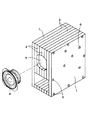
これを具体的に説明すると、本実施の形態に係るスピーカボックスは、図1に示す如く、ボックス本体の側壁を構成する2枚の側板1と、該各側板1間に介設される複数の中間板2から成るものであるが、特徴とするところは、各中間板2に共働して音道を画成する屈曲壁3を等しく形成して、これらの中間板2と上記2枚の側板1を積層してボルト6締めすることを特徴とするものである。従って、各側板1と各中間板2には、ボルト6を挿通するための挿通孔4を屈曲壁3を含めて一様に穿設しておくものとする。
【0011】
又、上記の屈曲壁3に関しては、経済的に安価なNC機械加工により切り抜き状に形成するものであるから、設計通りの如何なる屈曲形状を施すことも可能であるが、この場合には、少なくとも、図2にも示す如く、音道のコーナー部に曲線形状を付与すると共に、音道の広がり形状にも曲線形状を付与して、反射・気流の乱れが少なく音の濁りもなくなるように工夫することが好ましい。
【0012】
依って、本実施の形態に係るスピーカボックスを組み立てる場合には、2枚の側板1の間に任意枚数の中間板2を介在させて、上記した各挿通孔4にボルト6を挿通して、当該各ボルト6の先端部をナット7で個々に締め付ければ、これにより、図3に示す如く、箱型のスピーカボックスが簡単に組み付けられると同時に、ボックス本体の内部には、各中間板2に形成された屈曲壁3により理想的に屈曲した音道が精度をもって画成されることとなる。
【0013】
尚、この組み付けられたボックス本体にスピーカユニット8を取り付けるためには、例えば、図4に示す如く、積層された中間板2の前面側に取付孔5をカッター等で穿設して、当該取付孔5にスピーカユニット8を取り付けるものとするが、この場合には、具体的には図示しないが、カッター等による切断を容易とする切離溝を予め形成しておけば、切断作業が容易となる。又、切離溝の形成に際しては、複数形成して、スピーカユニット8の大きさに応じて、これに対応する切離溝を切り離すことも可能である。但し、これは、その一例であって、その他の方法で、スピーカユニット8をボックス本体に取り付けることも可能である。
【0014】
従って、本実施の形態に係るバックロード・ホーン用スピーカボックスの下では、各中間板2に対して、等しく音道を画成する屈曲壁3をNC機械加工により形成するだけで、ボックス本体の内部に所望の音道を精度をもって画成できるので、従来のものと比較すると、製作が頗る容易となって、量産性に富み、安価なスピーカボックスを初めて提供できることとなる。
【0015】
又、この中間板2と側板1を積層してボルト6締めすることは、釘打ちや接着剤の使用やハタガネ作業が要らなくなるので、これによっても、製作が容易となることは言うまでもないが、これに加えて、各中間板2が強固に締め付けられる結果、屈曲壁3同士間に隙間が生じることがないので、音もれの心配もなくなる。但し、必要に応じて、屈曲壁3同士を接着剤で接着することを否定するものではない。
【0016】
更に、NC機械加工によれば、屈曲した音道のコーナー部や音道の広がり形状をも曲線状に加工できるので、反射・気流の乱れが少なく音の濁りもなくなる。
【0017】
又、積層構造の下では、中間板2の枚数を任意に増減することが可能となるので、これにより、音の変化が楽しめると共に、積層される中間板2に関しては、共振モードの異なる板材を用意して、それを交互に積層するように構成すれば、ボックス本体の共振を押えることも可能となる。
【0018】
【発明の効果】
以上の如く、本発明は、上記構成の採用により、2枚の側板間に介設される複数の中間板に対して、経済的に安価なNC機械加工を施して、音道を画成する屈曲壁を等しく形成して、後は、これらの中間板と2枚の側板を積層してボルト締め又は接着剤で接着するだけで、本体内部に精度の高い屈曲した音道を有するスピーカボックスが得られるので、誰でもが簡単にスピーカボックスを製作できることは言うまでもないが、特に、上記構成の下では、量産性に富み、安価なスピーカボックスを提供できる。
【0019】
又、特に、積層に際して、ボルト締めを採用すれば、屈曲壁同士間に不要な隙間が生じることがないので、音もれも一挙に解消できると共に、中間板の枚数を適宜決定することにより、音の変化も楽しめる。更に、音道のコーナー部も曲線形状にできると共に、音道の広がり形状も計算にのっとった曲線形状となすことができるので、反射・気流の乱れが少なく音の濁りもなくなる。
【図面の簡単な説明】
【図1】本発明の実施の形態に係るバックロード・ホーン用スピーカボックスの分解斜視図である。
【図2】中間板の単体の側面図である。
【図3】ボックス本体を組み立てた状態を示す斜視図である。
【図4】組み立てられたボックス本体にスピーカユニットを取り付ける取付孔を穿設した状態を示す斜視図である。
【符号の説明】
1 側板
2 中間板
3 屈曲壁
4 挿通孔
5 取付孔
6 ボルト
7 ナット
8 スピーカユニット[0001]
BACKGROUND OF THE INVENTION
The present invention relates to a speaker box for a backload horn having a sound path bent in a complicated manner inside a main body.
[0002]
[Prior art]
Between audiophiles, even a small speaker unit can radiate high and medium sounds from the front of the speaker unit directly, and low frequencies coming out from the back can be reproduced in orthodox through a long sound path, improving the sense of volume in the low range. Due to its advantages, the back load horn system has attracted much attention.
[0003]
For this reason, various attempts have been made to develop a speaker box for use in such a backload horn system. However, the speaker box forms a long, complicatedly bent sound path for amplifying bass. Therefore, the formation of this sound path imposes various restrictions on design and production.
[0004]
Therefore, at present, as described in “Steeo (July 2000 issue)” issued by Ongaku no Tomo Co., Ltd., etc., wooden boards such as lauan plywood and china plywood are cut into desired dimensions, A box-shaped box body is obtained by appropriately assembling plate materials of various sizes using nails and adhesives, while a sound path for low-frequency amplification is formed inside the box body, and this is used as a backload horn. It is used as a speaker box.
[0005]
[Problems to be solved by the invention]
However, in such a conventional speaker box, a large number of wooden plate materials must be cut into predetermined dimensions, and these must be assembled manually with high accuracy. Was not suitable. In addition, although the ideal sound path for a backload horn is ideally a long curved shape that is intricately bent, it is complicated simply by combining rectangular plates. Since it is practically impossible to form a bent sound path, the advantages of the back load horn cannot be fully utilized. Since it was difficult to obtain, there was a risk of causing sound leakage due to this.
[0006]
[Means for Solving the Problems]
The present invention was developed to effectively solve the problems of such a conventional backload horn speaker box, and is a backload horn speaker box having a bent sound path inside the main body, It consists of two side plates and a plurality of intermediate plates interposed between the side plates, and a plurality of intermediate plates that extend integrally inward from their inner edges to ensure a constant distance from each other. bending wall formed equal to, by adhering these intermediate plates and two bolts or a plate laminating adhesives, sound path successive bent defined from each bent wall in the main body The structure which has was adopted.
[0007]
Therefore, in the present invention, economically inexpensive NC machining is applied to the plurality of intermediate plates interposed between the two side plates so that the bent walls that define the sound path are equalized. After forming, after simply laminating these intermediate plates and two side plates and bonding them with bolts or an adhesive , a speaker box with a highly accurate bent sound path inside the main body can be obtained. It goes without saying that anyone can easily manufacture a speaker box, but in particular, under the above configuration, an inexpensive speaker box with high productivity can be provided.
[0008]
Further, in particular, when stacked, lever to adopt a bolted, since does not occur undesired gaps between the bent walls together, the sound leakage even with possible to solve at a stroke, by appropriately determining the number of intermediate plates You can also enjoy sound changes. Furthermore, since the corner portion of the sound path can be made into a curved shape and the shape of the sound path can be made into a curved shape according to the calculation, there is little disturbance of reflection and air current, and there is no sound turbidity.
[0009]
DETAILED DESCRIPTION OF THE INVENTION
Hereinafter, the present invention will be described in detail based on a preferred embodiment shown in the drawings. The speaker box for a backload horn according to the embodiment is also a speaker box using a wooden board material such as a fiber board (MDF). However, the difference from the prior art is that the box body has a laminated structure.
[0010]
Specifically, as shown in FIG. 1, the speaker box according to the present embodiment includes two
[0011]
The
[0012]
Therefore, when the speaker box according to the present embodiment is assembled, an arbitrary number of
[0013]
In order to attach the
[0014]
Therefore, under the backload horn speaker box according to the present embodiment, the
[0015]
In addition, it is needless to say that this
[0016]
Further, according to NC machining, the curved sound path corner and the sound path spreading shape can be processed into a curved line, so that there is little disturbance of reflection and air flow and no turbidity of sound.
[0017]
Also, under the laminated structure, the number of
[0018]
【The invention's effect】
As described above, according to the present invention, by adopting the above configuration, an economically inexpensive NC machining is performed on a plurality of intermediate plates interposed between two side plates to define a sound path. A speaker box having a highly accurate bent sound path inside the main body can be obtained by simply forming the bent wall and then laminating these intermediate plates and two side plates and bonding them with bolts or an adhesive. Since it can be obtained, it goes without saying that anyone can easily manufacture a speaker box. However, particularly under the above configuration, an inexpensive speaker box with high productivity can be provided.
[0019]
Further, in particular, when stacked, lever to adopt a bolted, since does not occur undesired gaps between the bent walls together, the sound leakage even with possible to solve at a stroke, by appropriately determining the number of intermediate plates You can also enjoy sound changes. Furthermore, since the corner portion of the sound path can be made into a curved shape and the shape of the sound path can be made into a curved shape according to the calculation, there is little disturbance of reflection and air current, and there is no sound turbidity.
[Brief description of the drawings]
FIG. 1 is an exploded perspective view of a speaker box for a backload horn according to an embodiment of the present invention.
FIG. 2 is a side view of a single intermediate plate.
FIG. 3 is a perspective view showing a state in which the box body is assembled.
FIG. 4 is a perspective view showing a state in which a mounting hole for attaching a speaker unit is formed in the assembled box body.
[Explanation of symbols]
1
Claims (1)
Priority Applications (1)
| Application Number | Priority Date | Filing Date | Title |
|---|---|---|---|
| JP2002001161A JP3840413B2 (en) | 2002-01-08 | 2002-01-08 | Speaker box for back load horn |
Applications Claiming Priority (1)
| Application Number | Priority Date | Filing Date | Title |
|---|---|---|---|
| JP2002001161A JP3840413B2 (en) | 2002-01-08 | 2002-01-08 | Speaker box for back load horn |
Publications (3)
| Publication Number | Publication Date |
|---|---|
| JP2003204586A JP2003204586A (en) | 2003-07-18 |
| JP2003204586A5 JP2003204586A5 (en) | 2005-10-27 |
| JP3840413B2 true JP3840413B2 (en) | 2006-11-01 |
Family
ID=27641355
Family Applications (1)
| Application Number | Title | Priority Date | Filing Date |
|---|---|---|---|
| JP2002001161A Expired - Lifetime JP3840413B2 (en) | 2002-01-08 | 2002-01-08 | Speaker box for back load horn |
Country Status (1)
| Country | Link |
|---|---|
| JP (1) | JP3840413B2 (en) |
Cited By (1)
| Publication number | Priority date | Publication date | Assignee | Title |
|---|---|---|---|---|
| RU2519852C1 (en) * | 2012-11-30 | 2014-06-20 | Алексей Юрьевич Химичев | Acoustic horn and method of making same (versions) |
Families Citing this family (6)
| Publication number | Priority date | Publication date | Assignee | Title |
|---|---|---|---|---|
| GB2408404A (en) * | 2003-11-18 | 2005-05-25 | Sonaptic Ltd | Fabrication of enclosures for sonic devices, e.g. speakers |
| JP4524762B2 (en) | 2005-05-17 | 2010-08-18 | 株式会社村田製作所 | Speaker box and speaker device |
| JP5198959B2 (en) * | 2007-07-27 | 2013-05-15 | パナソニック株式会社 | Speaker device |
| JP4811881B2 (en) * | 2009-03-18 | 2011-11-09 | 東京エレクトロン株式会社 | Substrate heat treatment equipment |
| JP6313663B2 (en) * | 2014-06-03 | 2018-04-18 | 淳一 加賀美 | Back load horn type speaker box |
| WO2021033609A1 (en) * | 2019-08-20 | 2021-02-25 | 株式会社Living Anywhere Garage | Enclosure, speaker system, and method for producing same |
-
2002
- 2002-01-08 JP JP2002001161A patent/JP3840413B2/en not_active Expired - Lifetime
Cited By (1)
| Publication number | Priority date | Publication date | Assignee | Title |
|---|---|---|---|---|
| RU2519852C1 (en) * | 2012-11-30 | 2014-06-20 | Алексей Юрьевич Химичев | Acoustic horn and method of making same (versions) |
Also Published As
| Publication number | Publication date |
|---|---|
| JP2003204586A (en) | 2003-07-18 |
Similar Documents
| Publication | Publication Date | Title |
|---|---|---|
| US9716940B2 (en) | Acoustic device | |
| JP3840413B2 (en) | Speaker box for back load horn | |
| JPH0750960B2 (en) | Improvement of loudspeaker enclosure | |
| EP2060147B1 (en) | Apparatus for reproduction of stereo sound | |
| US20120177218A1 (en) | Speaker unit and speaker system using same speaker unit | |
| DK2811756T3 (en) | Speaker | |
| CN108781315A (en) | Loudspeaker module with disparate modules shell geometry and similar acoustic characteristic | |
| CN213126444U (en) | Distributed mode speaker for installation in a structure | |
| US3239028A (en) | Sound reproduction system | |
| JP2007124005A (en) | Woody panel | |
| JP2010077738A (en) | Construction panel with loudspeaker function | |
| US10477292B2 (en) | Plastic acoustic enclosure | |
| US8774437B2 (en) | Speaker box and speaker device | |
| JP6256452B2 (en) | Speaker cabinet and speaker system using them | |
| US20140294220A1 (en) | Loudspeaker unit with two loudspeakers and a wedge-shaped body between the spaces adjoining the loudspeakers | |
| US8459404B2 (en) | Loudspeaker | |
| US20050133298A1 (en) | Speaker box for use in back-load horn | |
| JP3957678B2 (en) | Speaker enclosure | |
| US4718098A (en) | Multi-diaphragm artificial reverberation device | |
| US8180086B2 (en) | Speaker | |
| US11503388B1 (en) | Loudspeaker enclosures and loudspeaker devices | |
| JPH0110062Y2 (en) | ||
| JP2001333476A (en) | Speaker system | |
| US20060018491A1 (en) | Single-sided Bessel array | |
| JP2007235727A (en) | Speaker system |
Legal Events
| Date | Code | Title | Description |
|---|---|---|---|
| A621 | Written request for application examination |
Free format text: JAPANESE INTERMEDIATE CODE: A621 Effective date: 20041224 |
|
| A521 | Request for written amendment filed |
Free format text: JAPANESE INTERMEDIATE CODE: A523 Effective date: 20050906 |
|
| A977 | Report on retrieval |
Free format text: JAPANESE INTERMEDIATE CODE: A971007 Effective date: 20060424 |
|
| A131 | Notification of reasons for refusal |
Free format text: JAPANESE INTERMEDIATE CODE: A131 Effective date: 20060509 |
|
| A521 | Request for written amendment filed |
Free format text: JAPANESE INTERMEDIATE CODE: A523 Effective date: 20060615 |
|
| TRDD | Decision of grant or rejection written | ||
| A01 | Written decision to grant a patent or to grant a registration (utility model) |
Free format text: JAPANESE INTERMEDIATE CODE: A01 Effective date: 20060711 |
|
| A61 | First payment of annual fees (during grant procedure) |
Free format text: JAPANESE INTERMEDIATE CODE: A61 Effective date: 20060807 |
|
| R150 | Certificate of patent or registration of utility model |
Ref document number: 3840413 Country of ref document: JP Free format text: JAPANESE INTERMEDIATE CODE: R150 Free format text: JAPANESE INTERMEDIATE CODE: R150 |
|
| FPAY | Renewal fee payment (event date is renewal date of database) |
Free format text: PAYMENT UNTIL: 20100811 Year of fee payment: 4 |
|
| R250 | Receipt of annual fees |
Free format text: JAPANESE INTERMEDIATE CODE: R250 |
|
| FPAY | Renewal fee payment (event date is renewal date of database) |
Free format text: PAYMENT UNTIL: 20100811 Year of fee payment: 4 |
|
| FPAY | Renewal fee payment (event date is renewal date of database) |
Free format text: PAYMENT UNTIL: 20110811 Year of fee payment: 5 |
|
| R250 | Receipt of annual fees |
Free format text: JAPANESE INTERMEDIATE CODE: R250 |
|
| FPAY | Renewal fee payment (event date is renewal date of database) |
Free format text: PAYMENT UNTIL: 20110811 Year of fee payment: 5 |
|
| FPAY | Renewal fee payment (event date is renewal date of database) |
Free format text: PAYMENT UNTIL: 20120811 Year of fee payment: 6 |
|
| R250 | Receipt of annual fees |
Free format text: JAPANESE INTERMEDIATE CODE: R250 |
|
| FPAY | Renewal fee payment (event date is renewal date of database) |
Free format text: PAYMENT UNTIL: 20130811 Year of fee payment: 7 |
|
| R250 | Receipt of annual fees |
Free format text: JAPANESE INTERMEDIATE CODE: R250 |
|
| R250 | Receipt of annual fees |
Free format text: JAPANESE INTERMEDIATE CODE: R250 |
|
| R250 | Receipt of annual fees |
Free format text: JAPANESE INTERMEDIATE CODE: R250 |
|
| R250 | Receipt of annual fees |
Free format text: JAPANESE INTERMEDIATE CODE: R250 |
|
| R250 | Receipt of annual fees |
Free format text: JAPANESE INTERMEDIATE CODE: R250 |
|
| R250 | Receipt of annual fees |
Free format text: JAPANESE INTERMEDIATE CODE: R250 |
|
| R250 | Receipt of annual fees |
Free format text: JAPANESE INTERMEDIATE CODE: R250 |
|
| R250 | Receipt of annual fees |
Free format text: JAPANESE INTERMEDIATE CODE: R250 |
|
| R250 | Receipt of annual fees |
Free format text: JAPANESE INTERMEDIATE CODE: R250 |
|
| R250 | Receipt of annual fees |
Free format text: JAPANESE INTERMEDIATE CODE: R250 |
|
| EXPY | Cancellation because of completion of term |