JP3840407B2 - Bearing shaft measurement method - Google Patents

Bearing shaft measurement method Download PDF

Info

Publication number
JP3840407B2
JP3840407B2 JP2001369237A JP2001369237A JP3840407B2 JP 3840407 B2 JP3840407 B2 JP 3840407B2 JP 2001369237 A JP2001369237 A JP 2001369237A JP 2001369237 A JP2001369237 A JP 2001369237A JP 3840407 B2 JP3840407 B2 JP 3840407B2
Authority
JP
Japan
Prior art keywords
bearing
axis
shaft
base
rotor
Prior art date
Legal status (The legal status is an assumption and is not a legal conclusion. Google has not performed a legal analysis and makes no representation as to the accuracy of the status listed.)
Expired - Fee Related
Application number
JP2001369237A
Other languages
Japanese (ja)
Other versions
JP2003166906A (en
Inventor
喜隆 金田
元三 入江
則宏 井上
和紀 才木
Current Assignee (The listed assignees may be inaccurate. Google has not performed a legal analysis and makes no representation or warranty as to the accuracy of the list.)
Denso Ten Ltd
Original Assignee
Denso Ten Ltd
Priority date (The priority date is an assumption and is not a legal conclusion. Google has not performed a legal analysis and makes no representation as to the accuracy of the date listed.)
Filing date
Publication date
Application filed by Denso Ten Ltd filed Critical Denso Ten Ltd
Priority to JP2001369237A priority Critical patent/JP3840407B2/en
Publication of JP2003166906A publication Critical patent/JP2003166906A/en
Application granted granted Critical
Publication of JP3840407B2 publication Critical patent/JP3840407B2/en
Anticipated expiration legal-status Critical
Expired - Fee Related legal-status Critical Current

Links

Images

Landscapes

  • Testing Of Devices, Machine Parts, Or Other Structures Thereof (AREA)

Description

【0001】
【発明の属する技術分野】
本発明は、軸受の軸垂を測定する軸垂測定方法に関する。
【0002】
【従来の技術】
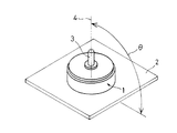
図24は、ベース2に立設するモータ1の主要部の概観を示す斜視図である。モータ1は、ベース2に対する回転軸3の角度θによって、その品質が影響し、回転軸3の角度θの傾き具合は、軸垂と呼ばれる。軸垂は、ベース2に垂直な垂直線に対するモータ1の回転軸線4の傾きである。ベース2に立設される軸受自体がベース2に対して傾いている場合は、軸受5に嵌め込まれる回転軸3もまたベース2に対して傾く。
【0003】
したがって、モータ1の組立工程において、モータ1の軸受5の軸垂を測定し、管理することが重要管理項目となっている。たとえばコンパクトディスクを回転するためのスピンドルモータでは、回転軸線4は、ベース2に垂直な垂直線に対して、±0.13度以内の範囲の傾きに抑えられる。
【0004】
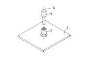
図25は、軸受5の軸垂を測定するための基準軸7を示す斜視図である。従来の技術の軸垂測定方法では、軸受軸線6を測定するために基準軸7が用いられる。従来の軸垂測定方法は、基準軸7を軸受5に嵌め込み、基準軸7とベース2とを固定した状態で、ベース2に対する基準軸7の傾きを測定して基準軸7の軸垂を求める。従来の技術の軸垂測定方法では、この求められた基準軸7の軸垂を、軸受5の軸垂として近似する。
【0005】
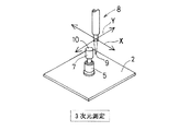
図26は、従来の技術の軸垂測定装置8の一部を示す斜視図である。従来の技術の軸垂測定装置8は、接触式変位センサ9を有する。接触式変位センサ9が、軸受5に嵌め込まれた基準軸7の端面10を、水平な2方向X、Yに走査する。これによって基準軸7の端面10のベース2に対する傾きを測定して、基準軸7の軸垂を求める。この基準軸7の軸垂を軸受5の軸垂として近似する。
【0006】
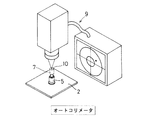
図27は、他の従来の技術の軸垂測定装置9の一部を示す斜視図である。他の従来の技術の軸受測定装置9は、非接触変位センサによって基準軸7の軸垂を測定する。軸受測定装置9は、基準軸一端面10に向けて光を照射し、一端面10から反射した光を受光することによって、基準軸一端面10のベース2に対する傾きを測定して、基準軸7の軸垂を求める。この基準軸7の軸垂を軸受5の軸垂として近似する。
【0007】
また軸受に嵌め込まれた軸の心振れを測定する装置が開示されている。たとえば、特開2000−205857号公報に開示される軸受製造装置は、軸受を測定用のロータ軸に嵌め込み、ロータ軸を回転させて、ロータ軸の外周面の変位を測定する。また特開平9−79872号公報に開示されるノズル検査装置は、ノズル端面上方に設けられるモニタが、軸受に嵌め込まれ回転するノズルの心振れを表示する。
【0008】
【発明が解決しようとする課題】
図26および図27に示す従来の技術の軸垂測定装置8,9では、基準軸7に寸法誤差がある場合は、基準軸7の軸垂と軸受5の軸垂とが等しくならず、基準軸の軸垂を軸受の軸垂として近似することができない。
【0009】
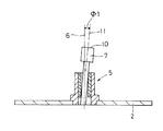
図28は、軸受5の軸線6に対して基準軸7の軸線がずれた場合を示す断面図である。基準軸7の寸法誤差によって、基準軸7の外径が、軸受5の内径よりも小さく形成された場合には、基準軸7は、軸受5の軸線6に対して基準軸7の軸線11がずれて、軸受5に嵌合されるおそれがある。また基準軸7の寸法公差によって、基準軸7と軸受5との間に隙間が形成されると、ガタついて確実に固定することができないことがある。
【0010】
軸受5の軸線6との間にずれΦ1が生じる場合には、軸受5の軸線6と基準軸7の軸線11が一致しない。したがって図26および図27に示す従来の軸垂測定装置8,9は、基準軸7の軸線11しか測定することができず、真の軸受5の軸線6を測定することができない。
【0011】
図29は、基準軸7の端面10が基準軸7の軸線11に垂直な仮想面12に対して傾斜して形成される場合を示す断面図である。図29に示すように、基準軸7の一端面10が仮想面12に対して傾斜する場合には、基準軸7の軸線に沿って一端面10に照射された光の反射光は、基準軸7の軸線11からずれて反射する。
【0012】
図27に示す従来の技術の軸垂測定装置9は、光の反射光によって、基準軸7の軸線を計測しているので、図29のように、反射光と基準軸の軸線11との間にずれΦ2がある場合には、基準軸7の軸線11を測定することができない。したがって軸受5の軸垂を求めることができない。
【0013】
同様に特開2000−205857号公報および特開平9−79872号公報に開示される軸受に嵌め込まれた軸の心振れを測定する装置であっても、軸受に嵌め込まれる軸に寸法誤差がある場合には、軸受の軸垂を測定することができない。
【0014】
したがって、本発明の目的は、基準軸の寸法精度にかかわらず、正確な軸受の軸垂を測定することができる軸受の軸垂測定方法を提供することである。
【0015】
【課題を解決するための手段】
本発明は、ベースに立設される軸受の軸垂を測定する方法であって、
軸受に嵌合可能に形成される基準軸を前記軸受内に回転可能に嵌め込み、
前記基準軸の一端面に光を照射して反射光を検出するとともに、前記基準軸を回転させ、ベースに平行な平面内における反射光の回転軌跡を調べ、
前記回転軌跡の重心を求め、前記重心に基づいて軸受の軸垂を求め
軸垂測定対象を、ロータとステータとを含んで構成されるモータとして形成するときに、
前記基準軸と回転翼とが設けられるロータを前記軸受に嵌め込み、気体を回転翼に吹き付けてロータを回転させて軸受の軸垂を求めることを特徴とする軸受の軸垂測定方法である。
【0016】
本発明に従えば、ベースに垂直な垂直線に対する軸受軸線の傾きを測定することができる。基準軸の寸法に誤差がない場合には、基準軸の一端面に照射された光は、軸受軸線のベースに対する傾きに応じて反射する。ベースに垂直な垂直線に対して軸受軸線の傾きが大きくなるにつれて、基準軸の一端面は、ベースに対して傾き、光の反射角が大きくなる。すなわち照射光と反射光を2次元面内に投影した場合に、照射光点から反射光点までの距離が大きくなる。
【0017】
基準軸の寸法に誤差がない場合には、2次元面内に投影される反射光点は、基準軸の回転にかかわらず一箇所の位置に示され、軸受軸線の傾きと比例関係にある。したがって反射光点を求めることによって、軸受軸線の傾き、すなわち軸受の軸垂を算出することができる。
【0018】
また、図28および図29に示すように基準軸の寸法誤差によって、2次元面内に投影した反射光点と、軸受軸線を2次元面内に投影した点とが異なる場合がある。しかし本発明に従えば、基準軸を回転させて、ベースに平行な2次元面内に投影した反射光の回転軌跡の重心に基づいて、軸受の軸垂を算出することによって、基準軸の寸法誤差にかかわらず、正確な軸受の軸垂を得ることができる。
【0019】
たとえば図28に示すように、軸受軸線と基準軸の軸線とがずれた場合であっても、本発明に従って基準軸を回転させることによって、基準軸は軸受軸線まわりに回転し、基準軸の一端面もまた、軸受軸線まわりに回転する。たとえば2次元面内に投影した反射光は、閉ループ状の軌跡を描く。軸受軸線と基準軸の軸線とのずれが小さくなるにつれて、前記閉ループは、その重心に向かうように小さくなり、軸受軸線と基準軸の軸線とのずれがない場合には、軸受軸線によって決定される一点で表される。
【0020】
したがって反射光が2次元面内に投影される点が描く回転軌跡、たとえば閉ループ状の軌跡の重心は、軸受軸線と基準軸の軸線との軸線にかかわらず、軸受軸線によって決定される位置である。したがって回転軌跡の重心位置を求めることによって、基準軸の誤差の影響を除いた正確な軸受の軸線の傾きを調べることができる。
【0021】
またたとえば、図29に示すように、基準軸の一端面が基準軸軸線と垂直でない場合であっても、同様に、基準軸を回転させることによって、2次元面内に投影した反射光は、回転軌跡を描く。この回転軌跡の重心位置を求めることによって、基準軸の誤差の影響を除いた正確な軸受の軸線の傾きを調べることができる。
【0022】
このように基準軸の外周径の誤差および端面の形状誤差が形成される場合であっても、基準軸を回転させ、2次元面内たとえばベースに平行な面に投影される反射光点が描く回転軌跡の軌跡の重心を求めることによって、真の軸受軸線を得ることができ、正確な軸受の軸垂を求めることができる。
また、基準軸を回転させるために、回転翼を有し、基準軸が設けられるロータが用いられる。回転翼に向かって気体を吹き付けることによって、回転翼とともにロータを軸受軸線まわりに回転させて、軸受の軸垂を測定することができる。
またロータをモータの一部として構成した場合に、回転翼がロータ周囲の空気を攪拌する。これによってステータのコイルによって加熱された周囲の空気がモータ近辺に留まることを防止し、モータに冷却機能を持たせることができる。
【0040】
また本発明は、前記軸受に嵌め込まれたロータが回転することによって、前記回転翼は、前記軸受と反対方向に向かう気流を生じることを特徴とする。
【0041】
本発明に従えば、ロータが回転することによって回転翼から軸受と反対方向に向かう気流を生じるように形成される回転翼が用いられる。これによってロータに、軸受に向かって押さえつけられるスラストバイアス力を作用させることができる。スラストバイアス力が作用するロータは、回転軸線方向に変位することが防止され、モータの回転不良を防止することができる。
【0045】
また本発明は、基準軸回転時に、オートコリメータを用いて、前記基準軸の一端面に光を照射して反射光を検出することを特徴とする。
【0046】
本発明に従えば、オートコリメータを用いることによって、基準軸の一端面に光を照射して反射光を良好に検出することができる。
【0075】
【発明の実施の形態】
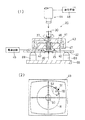
図1は、本発明の実施の一形態の軸受の軸垂測定装置20の一部を示し、図1(1)は、軸垂測定装置20の断面図であり、図1(2)は、軸垂測定時の表示画面を示す正面図である。軸垂測定装置20は、ベース22に立設された軸受25の軸垂を測定する装置である。軸受25の軸垂は、軸受25の軸線26がベース22に垂直な垂直線に対して傾く角度である。
【0076】
軸垂測定装置20は、基準軸27と、回転手段40と、変位検出手段であるオートコリメータ44とを含んで構成される。基準軸27は、軸受25に嵌合可能に形成される。基準軸27は、軸受25の内径とほぼ等しい外径を有し、軸線方向一端面30は、基準軸27の軸線31に垂直な平面に形成される。また、基準軸一端面30は、鏡面であり、たとえば一端面30にメッキ処理が行われて鏡面となる。またたとえば、一端面30に鏡が貼り付けられる。
【0077】
一端面30は、基準軸27の軸受挿入方向上流側の面である。基準軸27は、挿入方向下流側の端部に比べて挿入方向上流側端部の外径が大きく、2段の円筒状に形成される。基準軸27は、後述する軸受25に対する摩擦抵抗が小さく、かつ軸受のメタルよりも柔らかい樹脂が外周部に形成される。たとえばアクリルまたはABS樹脂(アクリロニトリル・ブタジエン・スチレン樹脂)が基準軸27の表面にコーティングされる。またたとえば、基準軸27自体がアクリルまたはABS樹脂から成ってもよい。
【0078】
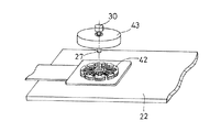
回転手段40は、基準軸27を回転駆動する。回転手段40は、たとえば電磁力によって回転するモータによって実現され、ロータ治具43とコイル治具42とを含んで構成される。ロータ治具43は、計測用ロータ体41に基準軸27が嵌合される。計測用ロータ体41は、一方が開放される有底筒状に形成される。計測用ロータ体41の底部には、基準軸27が挿通する挿通孔が形成される。この挿通孔に基準軸27が圧入される。圧入された基準軸27は、その軸線が、計測用ロータ体41の軸線と同一線上に設けられる。
【0079】
コイル治具42は、略円筒状に形成され、軸受25の外周を囲んでベース22に固定される。コイル治具42は、コイル46が巻回されるコアを有する。またコイル治具42は、コイル46に電流を供給するための電源回路45が接続される。
【0080】
ロータ治具43は、基準軸27が軸受25に嵌め込まれた状態で、ベース22に固定されたコイル治具42を覆う。ロータ治具43は、コイル治具42に臨む部分にマグネット47が設けられる。このようなロータ治具43およびコイル治具42を含む回転手段40は、コイル治具42のコイル46が電通されることによって、ロータ治具43を軸受25まわりに回転させる。
【0081】
オートコリメータ44は、基準軸27の一端面30に光を照射し、一端面30から反射した反射光を検出する。オートコリメータ44は、ベース22に対して垂直な方向で、基準軸27の一端面30に向かって入射光を照射する。また、オートコリメータ44は、回転中に変化する基準軸27の一端面30のベース22に対する傾きを測定し、測定データを表示手段48に与える。
【0082】
表示手段48は、オートコリメータ44によって測定された反射光の測定データに基づいて、反射光がベース22に平行な2次元面内に投影された点51を表示する。たとえば表示手段は、CRT(Cathode Ray Tube:陰極線管)モニタを含んで実現される。
【0083】
基準軸一端面30がベース22に対して傾いている場合には、表示位置51は、図1(2)に黒点で示すように、原点位置50からずれて配置される。表示位置51は、基準軸一端面30がベース22に対して傾くにつれて、原点位置50から離れて表示される。
【0084】
たとえば図28で示したように基準軸27に寸法誤差があるとき、基準軸一端面30のベース22に対する傾きは、基準軸27の回転とともに変化する。具体的には、基準軸27が軸受25の軸線に対して傾いている場合、基準軸27を回転させることによって、軸受25の軸線に対する傾きは、同じ角度を保ち、その傾きの方向が回転に伴い巡回的に変化する。これによって基準軸一端面30の傾きの方向は、基準軸が一回転すると元の傾きの方向に戻る。したがって表示画面49に表示される表示点51も、基準軸27が一回転すると元の位置に戻る。このように表示画面49に表示される表示点51は、基準軸27が回転することによって、その軌跡52は、表示画面内に閉ループ状となる回転軌跡を描く。なお、閉ループ形状が得られない場合は、その回転軌跡の曲線を平均化して擬似閉ループを求めるようにしてもよい。
【0085】
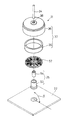
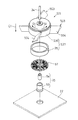
図2は、軸垂測定対象である軸受25が設けられるブラシレススピンドルモータ21を示す分解斜視図である。軸受25は、ベース22から立設する。軸受25は、たとえばコンパクトディスク(CD)またはデジタルバーサタイルディスク(DVD)等の円板状記憶媒体を回転させるモータ21の一部を構成する。モータ21は、円板状記録媒体を振れなく回転させる必要があり、モータ21の出力軸34は、ベース22に対して垂直に延びることが好ましい。出力軸34のベースに対して垂直に延びる垂直線に対する傾きの許容値は小さく、たとえば垂直線に対して、±0.13度以内の傾きαに製造される。この許容寸法を満たすモータ21を製造するために、特に軸受25の軸垂を正確に測定する必要がある。
【0086】
モータ21は、軸受25と、ステータを構成するコア57と、ロータ37とを含んで構成される。コア57は、所定の形状に形成されるコアシートが積層される突極にコイルが巻回される。またロータ37は、マグネット35と、マグネット35を収容するロータ体36とを含んで構成される。マグネット35は、ロータ体36の内周面に固定される。
【0087】
軸受25は、たとえば焼結含有軸受である。焼結含有軸受は、円筒形に形成され、潤滑油が含油されるメタル54とメタル54の外周面を覆うハウジング53とを含んで構成される。メタル54に嵌め込まれた出力軸34が回転すると、メタル54に含浸されていた潤滑油が、出力軸34とメタル54の内周面との間にしみだす。これによって出力軸34を円滑に回転させることができる。
【0088】
軸受25、コア57、ロータ37および出力軸34は、ともに同一線上に配置されるように形成される。コア57は、軸受25の外周部を覆ってベース22に固定される。ロータ体36は、厚み方向に挿通する挿通孔38が形成される。出力軸34は、前記挿通孔38に圧入される。モータは、コア57とマグネットとが隙間を開けて対向した位置に配置される。
【0089】
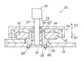
図3は、軸垂測定装置20のロータ治具43付近を拡大して示す断面図である。また図4は、軸垂測定装置20のロータ治具43付近を示す斜視図である。軸受25の軸垂は、ベース22に軸受25が固定された状態で測定される。したがって図2に示すコア57、ロータ37および出力軸34をモータ21として組み立てる前に軸受25の軸垂測定が行われる。モータ21として組み立てる前に軸受25の軸垂を測定することができるので、軸垂許容値を超えた軸受25を取り除いて、正常な軸受のみをモータ21として構成することができる。
【0090】
ハウジング53は、軸線方向一方側A1部分に設けられ、半径方向外方に突出するベース当接部58が形成される。またハウジング53は、ベース当接部58に連なり、ベース当接部58からさらに軸線方向一方側A1に突出し、ベース当接部58よりも半径方向内方に嵌入したカシメ片60とが形成される。またカシメ片60の内周面には、ハウジング25の軸線方向一方側A1を塞ぐ底板61が嵌め込まれる。カシメ片60の先端には、二股に分かれる二股部59が形成される。
【0091】
ベース当接部58がベース22にハウジング軸線方向一方側A1から当接し、カシメ片60がベース22を厚み方向に挿通した状態で、二股部分59が両側に開くように折り曲げられる。二股部分59の折り曲げられた一方の部分は、ベース22にハウジング53の軸線方向他方側A2から当接する。これによってベース当接部60の軸線方向一方側A1の面と、二股部59の軸線方向他方側の面A2とが協働して、ベース22を挟持する。これによって軸受25がベース22に締結される。
【0092】
上述のように、軸受25は、カシメ片59がカシメられてベース22に固定されるので、ベース22に対して、軸受軸線26が垂直に配置されないおそれがある。したがって軸受25の軸垂を正確に測定し、軸垂が許容範囲を超えた軸受25を取り除く必要がある。
【0093】
軸垂測定装置20は、モータ21として構成されるロータ37およびコア57に替えて、測定用の治具であるロータ治具43およびコイル治具42を有する。ロータ治具43およびコイル治具42は、ベース22および軸受25に着脱可能に形成される。これによって軸受25の軸垂測定後に、各治具42,43を取外し、軸垂許容範囲内に収まる軸受25を次工程に進めることができる。ロータ治具43およびコイル治具42を、図2に示すモータを構成するコア57およびロータ37と類似した構成にすることによって、各治具43,42を新たに形成する手間を省くことができる。
【0094】
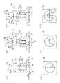
図5は、軸受25に嵌め込まれた基準軸27の状態を示す軸受部分の拡大断面図と、そのとき表示される表示画面49を示す。なお、図5において、時計まわりの角度を負とし、時計と反対まわりの角度を正とする。
【0095】
図5(1)には、基準軸27が寸法誤差なく形成され、軸受軸線26がベース22に対して垂直に延びる状態を示す。また、図5(2)は、図5(1)の状態での表示画面を示す。基準軸27に寸法誤差がない場合には、軸受25に嵌め込まれた基準軸27は、その軸線31が軸受軸線26と同一線上に延びる。また、基準軸27の一端面30が、基準軸27の軸線31に垂直な平面に形成される。したがって軸受25に嵌めこまれた基準軸27の一端面30は、ベース22に対して平行に配置され、ベース22に垂直な垂直線74に対して垂直な面となる。
【0096】
このように一端面30が、ベース22に対して平行になる場合、オートコリメータ44によって照射された入射光75に対する反射光76、すなわちベース22に対して垂直に入射する入射光75に対する反射光76は、入射光75と同じ経路をたどる。
【0097】
また、基準軸27が回転したとしても、基準軸27の軸線31と軸受軸線26とが同一線上に形成されるので、一端面30がベース22に対して傾くことがない。したがって、反射光76は、基準軸27の回転にかかわらずその反射方向が一定となる。これによってベース22に平行な2次元面55に投影される反射光76の位置は、基準軸27の回転にかかわらず、一点の位置51に投影される。
【0098】
表示手段48によって表示される表示画面49は、2次元平面55に投影される入射光75の位置が原点位置50となり、2次元平面55に投影される反射光76の位置が表示点51となる。したがって、図5(1)に示すように、基準軸27および軸受25に誤差がなく、軸受軸線26がベース22に対して垂直な場合、表示画面49は、図5(2)に示すように、表示画面内の原点位置50と等しい位置に表示点51が表示される。
【0099】
これによって、基準軸27の回転にかかわらず、原点位置50の一点に表示点51が表示された場合には、軸受軸線26とベース22に垂直な垂直線74とが等しく、軸受軸線26がベース22に垂直であることを示す。
【0100】
図5(3)には、基準軸27の外径が軸受25の内径よりも小さく形成され、軸受軸線26がベース22に対して垂直に延びる状態を示す。また図5(4)は、図5(3)の状態での表示画面を示す。
【0101】
基準軸27の寸法誤差によって、その外径が軸受25の内径よりも小さく形成される場合には、軸受25に嵌め込まれた基準軸27は、その軸線31が軸受軸線26に対して傾き、これによって基準軸27の一端面30が、軸受軸線26に垂直な平面77に対して傾く。軸受軸線26がベース22に垂直に延びるので、たとえば軸受軸線26に対して、基準軸27の軸線31がβ度傾いた場合は、基準軸27の一端面30は、ベース22に対してβ度傾く。
【0102】
一端面30が、ベース22に対してβ度傾いた場合、入射光75に対する反射光76は、入射光75から2β度傾いて反射する。また、基準軸27が回転した場合には、基準軸27の軸線31は、軸受軸線26まわりに回転し、一端面30のベース22に対する傾斜方向が変化する。また反射光76は、基準軸27の回転にともなってその反射方向が変化する。たとえば図5(3)に実線で示す位置にある基準軸27が、軸受軸線26まわりに180度角変位した位置を、図5(3)に2点鎖線で示す。このときの反射光176も、軸受軸線26まわりに180度移動し、一端面30入射光に対して、2βの角度で反射する。また基準軸27が一回転すると、反射光の方向も一回転し、元の位置に戻る。したがって、図5(4)に示すように表示画面に表示される表示点51は、回転軌跡の一例示である閉ループに沿って移動する。このとき表示点51は、軸受軸線26が2次元面55に投影される点、すなわち原点位置50を内に含む閉ループに沿って移動する。
【0103】
反射光は、基準軸27の回転にともなって、軸受軸線26まわりに移動する。軸受軸線26に対する基準軸27の軸線31の傾斜角度βが小さくなると、図5(1)に示す状態に近づき、閉ループが小さくなる。このとき閉ループは、閉ループの重心位置に向かって小さくなる。したがって閉ループの重心位置は、傾斜角度βにかかわらず、軸受軸線26に応じて決定される。したがって軌跡52の重心を計算で求めることによって、軸受軸線26ひいては、軸受25の軸垂を求めることができる。これによって基準軸27が軸受軸線26に対してずれた状態で、軸受25に嵌め込まれた場合であっても、軸受25の軸垂を求めることができる。
【0104】
図5(5)には、基準軸27の一端面30が、基準軸の軸線31に垂直な面に対して傾いて形成され、軸受軸線26がベース22に対して垂直に延びる状態を示す。また図5(6)は、図5(5)の状態での表示画面を示す。
【0105】
基準軸27の一端面30が、基準軸27の軸線31に垂直な面73に対して傾いて形成される場合には、軸受25に嵌め込まれた基準軸27の一端面30は、軸受軸線26に垂直な平面に対して傾く。軸受軸線26がベース22に垂直に延び、たとえば基準軸27の一端面30が、基準軸27に垂直な面73に対してγ度傾いた場合は、基準軸27の一端面30は、ベース22に対してγ度傾く。
【0106】
一端面30が、ベース22に対してγ度傾いた場合、反射光76は、入射光75に対して2γ度傾いて反射する。また、基準軸27が回転した場合には、基準軸27の一端面30が軸受25の軸線まわりに傾いて回転する。したがって図5(3)と同様に、反射光76は、基準軸27の回転にともなってその反射方向が変化する。これによって、ベース22に平行な2次元面55に投影される反射光76の軌跡52は、閉ループに沿って移動する。このとき表示点51は、軸受軸線26が2次元面55に投影される点、すなわち原点位置50を内に含む閉ループに沿って移動する。
【0107】
基準軸27の回転にともなって、軸受軸線26まわりに移動する。基準軸27の軸線31に対する基準軸27一端面30の傾斜角度γが小さくなると、図5(1)に示す状態に近づき、閉ループが小さくなる。このとき閉ループは、閉ループの重心位置に向かって小さくなる。したがって閉ループの重心位置は、傾斜角度γにかかわらず、軸受軸線26に応じて決定される。したがって軌跡52の重心を計算で求めることによって、軸受軸線26ひいては、軸受25の軸垂を求めることができる。これによって基準軸27の軸線31に垂直な面に対して、基準軸27の一端面30が傾斜していた場合であっても、軸受25の軸垂を求めることができる。
【0108】
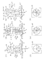
図6は、軸受25に嵌め込まれた基準軸27の状態を示す軸受部分の拡大断面図と、その状態で表示される表示画面49を示し、図6(1)には、基準軸27が寸法誤差なく形成され、軸受軸線26がベース22に対して垂直に延びる垂直線74に対して傾いている状態を示す。また、図6(2)は、図6(1)の状態での表示画面を示す。なお、図6において、時計まわりの角度を負とし、時計と反対まわりの角度を正とする。
【0109】
基準軸27の寸法誤差がない場合には、軸受25に嵌め込まれた基準軸27は、その軸線31が軸受軸線26と同一線上に延びる。また基準軸27の一端面30が、基準軸27の軸線31に垂直な平面に形成される。たとえば軸受軸線26が、ベース22に垂直な垂直線74に対してσ度傾いているとすると、軸受25に嵌めこまれた基準軸27の一端面30は、ベース22に平行な面77に対してσ度傾いた面となる。
【0110】
このように一端面30が、ベース22に対してσ度傾くので、ベース22に対して垂直な方向に照射された入射光75に対する反射光76は、入射光75から2σ度傾いて反射する。また、基準軸27が回転したとしても、基準軸27の軸線31と軸受軸線26とが同一線上に形成されるので、一端面30のベース22に対する傾きが変化することがない。したがって、反射光76は、基準軸27の回転にかかわらずその反射方向が一定となる。これによってベース22に平行な2次元面55に投影される反射光76の位置は、基準軸27の回転にかかわらず、一点の位置に投影される。
【0111】
したがって、図6(2)に示すように、基準軸27および軸受25に誤差がなく、軸受軸線26がベースに垂直な垂直線74に対して傾いている場合、表示画面49は、表示画面内の原点位置50からずれた一点に表示点51が表示される。このずれる量は、ベース22に垂直な垂直線74に対して、軸受軸線26が傾く角度σの2倍の角度となる。これによってこのずれ量を測定することによって、軸受軸線26の傾きを知ることができ、これによって軸受25の軸垂を求めることができる。
【0112】
図6(3)には、基準軸27の外径が軸受25の内径よりも小さく形成され、軸受軸線26がベース22に対して垂直に延びる垂直線74に対して傾いている状態を示す。また図6(4)は、図6(3)の状態での表示画面を示す。
【0113】
基準軸27の外径が軸受25の内径よりも小さく形成される場合には、軸受25に嵌め込まれた基準軸27は、その軸線31が軸受軸線26に対して傾き、たとえばβ度傾く。図6において、βは、時計まわりに傾き、負の値となる。また、たとえばベース22に垂直に延びる垂直線74に対して、軸受軸線26がσ度傾く。図6において、σは、反時計まわりに傾き、正の値である。このように、基準軸27の軸線31が軸受軸線26に対して傾き、かつ軸受軸線26が、ベース22に垂直な垂直線74に対して傾いた場合には、軸受25に嵌め込まれた基準軸27の一端面30は、ベース22に対して平行な面77に対して傾き、基準軸27の回転とともにその傾きが変化する。
【0114】
たとえば、図6(3)に、紙面に垂直な点において反時計まわりに最も角変位した状態の基準軸27を実線で示し、この状態の基準軸27の一端面30は、ベース22に対して(σ+β)度傾く。図6において、βが負の値であり、|β|>|σ|となるので、一端面30は、ベースに平行な面77に対して、反時計まわりに(|β|−σ)度傾く。
【0115】
したがってベース22に対して垂直な方向に照射された入射光75に対する反射光76は、入射光75から2(σ+β)度傾いて反射する。図6において、反射光は、入射光に対して、反時計まわりに2(|β|−σ)度傾いた方向に反射する。
【0116】
また、基準軸27が回転した場合には、基準軸27の軸線31は、軸受軸線26まわりに回転し、基準軸27の一端面30もまた軸受軸線26まわりに回転する。したがって、反射光76は、基準軸27の回転にともなってその反射方向が変化する。たとえば基準軸27が軸受軸線26まわりに180度角変位すると、基準軸27は、図5(3)において、2点鎖線で示す位置に移動し、ベース22に対して反時計まわりに最も傾いた状態となる。このとき基準軸27の一端面30は、ベース22に対して、(σ−β)度傾く。図6において、βが負の値であるので、一端面30は、ベースに平行な面77に対して、時計まわりに(σ+|β|)度傾く。このときの反射光176は、図6(3)に実線で示す方向から、軸受軸線26まわりに180度角変位するとともに、入射光75から2(σ−β)度傾いて反射する。図6において、反射光は、入射光に対して、反時計まわりに2(σ+|β|)度傾いた方向に反射する。
【0117】
反射光は、入射光に対して、2(σ+β)度から2(σ−β)度の間で回転する。したがって反射光は、ベース22に垂直な垂直線74に対して、軸受軸線26が傾く角度σの2倍である角度2σを必ず内に含んで、入射光まわりに回転する。すなわち入射光に対して、点から軸受軸線26が傾く角度σの2倍である角度2σに傾斜して延び、2次元平面55に投影される軸垂点78のまわりを反射光が移動する。
【0118】
軸受軸線26がベース22に垂直な垂直線74に対する角度σが大きくなるほど、閉ループは、真円から楕円形に変形する。しかし、軸垂測定対象となる軸受25は、その軸線26がベース22に垂直な垂直線74に対する傾斜角度σがすでに小さい値なので、閉ループは、真円に近い形状になる。また軸受軸線26に対する基準軸27の軸線31の傾斜角度βが、ゼロである場合には、図6(1)に示される状態となる。軸受軸線26に対する基準軸27の軸線31の角度βが大きくなるにつれて、軸垂点78を含む閉ループが大きくなる。
【0119】
これによって、図6(4)に示すように、表示画面49は、閉ループ状の軌跡52のほぼ重心位置に軸垂点78が形成される。したがって基準軸27を回転させることによって、反射光が2次元面55に投影された点が描く閉ループ状の軌跡52を測定し、その重心を求めることによって、軸垂点78を近似することができる。軸垂点78を求めることによって、軸受軸線26がベース22に垂直な垂直線74に対する角度σ、すなわち軸垂を求めることができる。また、軸受軸線26に対して基準軸27の軸線31がβ度傾いていても、閉ループの軌跡52の重心位置を求めることによって、正確な軸受25の軸垂を求めることができる。
【0120】
図6(5)には、基準軸27の一端面30が、基準軸の軸線31に垂直な面に対して傾いて形成され、軸受軸線26がベース22に対して垂直に延びる状態を示す。また図6(6)は、図6(5)の状態での表示画面を示す。
【0121】
基準軸27の一端面30が、基準軸27の軸線31に垂直な面73に対して傾いて形成される場合には、軸受25に嵌め込まれた基準軸27の一端面30は、軸受軸線26に垂直な平面73に対して傾き、たとえばγ度傾く。図6において、γは負の値である。また、たとえばベース22に垂直に延びる垂直線74に対して、軸受軸線26がσ度傾く。図6において、σは正の値である。このように、基準軸27の一端面30が基準軸27の軸線31に対して傾き、かつ軸受軸線26が、ベース22に垂直な垂直線74に対して傾いた場合には、軸受25に嵌め込まれた基準軸27の一端面30は、ベース22に対して傾き、基準軸27の回転とともにその傾きが変化する。
【0122】
たとえば、図6(5)の紙面に垂直な点において時計まわりに最も角変位した状態の基準軸27を実線で示し、この状態の基準軸27の一端面30は、ベース22に平行な面77に対して(σ+γ)度傾く。図6において、γが負の値であり、|γ|>|σ|となるので、一端面30は、ベースに平行な面77に対して、反時計まわりに(|γ|−σ)度傾く。
【0123】
したがって、ベース22に対して垂直な方向に照射された入射光75に対する反射光76は、入射光75から2(γ+σ)度傾いて反射する。図6において、反射光は、入射光に対して、反時計まわりに2(|γ|−σ)度傾いた方向に反射する。
【0124】
また、基準軸27が回転した場合には、基準軸27の軸線31は、軸受軸線26まわりに回転し、基準軸27の一端面30もまた軸受軸線26まわりに回転する。したがって、反射光76は、基準軸27の回転にともなってその反射方向が変化する。たとえば基準軸27が軸受軸線26まわりに180度角変位すると、基準軸27は、図6(5)において、2点鎖線で示す位置に移動し、ベース22に対して反時計まわりに最も傾いた状態となる。このとき基準軸27の一端面30は、ベース22に対して、(σ−γ)度傾く。図6において、γが負の値であるので、一端面30は、ベース22に平行な面77に対して、時計まわりに(σ+|γ|)度傾く。このときの反射光176は、図6(5)に実線で示す方向から、軸受軸線26まわりに180度角変位するとともに、入射光75から2(σ−γ)度傾いて反射する。図6において、反射光は、入射光に対して、反時計まわりに2(σ+|γ|)度傾いた方向に反射する。
【0125】
反射光は、入射光に対して、2(σ+β)度から2(σ−β)度の間で回転する。したがって反射光は、ベース22に垂直な垂直線74に対して、軸受軸線26が傾く角度σの2倍である角度2σを必ず内に含んで、入射光まわりに回転する。いいかえると、ベース22に平行な2次元面55に投影される反射光76の点は、軸受軸線26が2次元面55に投影された点を内に含む閉ループに沿って移動する。すなわち入射光に対して、点から軸受軸線26が傾く角度σの2倍である角度2σに傾斜して延び、2次元平面55に投影される軸垂点78のまわりを反射光が回転する。
【0126】
図6(4)、図6(5)の説明と同様に、表示画面49において、閉ループ状の軌跡52は、略円形に形成され、その重心位置に軸垂点78が形成される。したがって、上述のように基準軸27を回転させることによって、反射光が2次元面内に投影される点が描く閉ループ状の軌跡52を測定し、その重心を求めることによって、軸垂点78を求めることができる。
【0127】
これによって軸受軸線26がベース22に垂直な垂直線74に対する角度σ、すなわち軸垂を求めることができる。また、基準軸27の軸線31に垂直な面に対して基準軸27の一端面30がγ度傾いていても、閉ループの軌跡52の重心位置を求めることによって、正確な軸受25の軸垂を求めることができる。また反射光の軌跡は、必ずしも閉ループ状の軌跡を描かなくてもよい。たとえば反射光が回転するにつれて、回転軌跡がずれて、完全な閉ループを描かない場合であっても、オートコリメータ44または表示手段48に設けられる画像処理手段が、回転軌跡を閉ループ状の回転軌跡として近似することによってその近似した閉ループ状の軌跡に基づいて、軸受25の軸垂を求めることができる。
【0128】
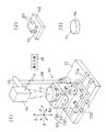
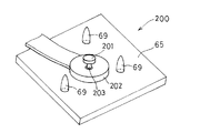
図7は、オートコリメータ44とベース22とを支持する支持台62を説明するための斜視図であり、図7(2)は乗載部65を示す斜視図であり、図7(3)は鏡面体64を示す斜視図である。軸垂測定装置20は、オートコリメータ44とベース22とを支持する支持台62を有する。
【0129】
支持台62は、ベース22を乗載する微動ステージ63と、微動ステージ63とオートコリメータ44との位置調整に用いられる鏡面体64と、オートコリメータ44を保持するオートコリメータ保持部68と、微動ステージ63およびオートコリメータ保持部68を支持する土台部72とを含んで構成される。
【0130】
微動ステージ63は、ベース22を乗載する乗載部65と、水平方向に沿って延びる第1方向Xまわりに乗載部65を角変位させる第1微動部66と、水平方向に沿って延び、かつ第1方向Xに直行する第2方向Yまわりに乗載部65を角変位させる第2微動部67とを有する。乗載部65は、上方に向かって突出する3つの支持片69と、マグネットベース70とが設けられる。ベース22は、3つの支持片69に当接して、ベース22が乗載部65上に乗載される。ベース22が乗載された状態で、マグネットベース70がベース22を磁力によって吸引することによって、ベース22が軸垂測定時にずれることを防止して、3つの支持片69上に確実に固定する。
【0131】
また微動ステージ63は、基準軸の回転軸線と垂直な面に沿う方向である第1方向Xおよび基準軸の回転軸線と垂直な面に沿う方向でありかつ第1方向に直交する第2方向Yに沿って、ベース22を移動させる移動手段を有する。たとえば、土台部72に形成される案内溝72a,72bに微動ステージ63が嵌り込む。案内溝72a,72bは、第1方向Xおよび第2方向Yに形成される。これによって微動ステージ63は、第1方向Xおよび第2方向Yに沿って平行に移動する。これによって、測定位置から微動ステージ63を移動させた状態で、ベース22および鏡面体64の取付けおよび取外しを行うことができる。オートコリメータ44などの測定装置がベース22の取付けおよび取外し作業を阻害せずに作業を容易に行うことができる。
【0132】
オートコリメータ44は、オートコリメータ保持部68によって保持される。オートコリメータ44は、微動ステージ63上に乗載されるベース22よりも上方に配置され、上方からベース22上に取付けられる基準軸27の一端面30に光を照射し、反射光を測定する。鏡面体64は、短円柱状に形成され、その厚さが均一に形成され、厚み方向両方の面が平坦に形成される。また鏡面体64の厚み方向一方側の面は、鏡面に形成される。
【0133】
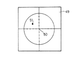
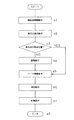
図8は、微動ステージを調整する前の状態であって、鏡面体70に入射光を照射したときの表示画面49を示す図であり、図9は、軸受25が立設されたベース22を乗載部65に乗載する状態を示す斜視図であり、図10は、軸受25の軸垂測定の手順を示すフローチャートである。以下図7〜図10を参照して、軸受25の軸垂測定手順を説明する。
【0134】
軸受25の軸垂測定の手順として、まず図7(1)に示すように、ステップs1では、3つの支持片69上に鏡面体70の鏡面71を上方にして鏡面体64を乗載する鏡面体乗載動作が行われる。鏡面体乗載動作が完了するとステップs2に進む。ステップs2では、オートコリメータ44によって、鏡面体70の鏡面71に向けて光を照射し、反射した反射光を測定し、表示手段48に表示する表示点表示動作が行われる。鏡面体70の鏡面71に対して、入射光の進む方向が垂直でない場合には、図8に示すように表示点51は、原点位置50からずれて配置される。ステップs3では、ステップs2によって表示画面49に表示された表示点51が、原点位置50にあるか否かを判断し、表示点51が原点位置50にある場合はステップs5に進み、そうでない場合はステップs4に進む。
【0135】
ステップs4では、微動ステージ63の第1微動部66および第2微動部67によって、乗載部65を第1方向Xおよび第2方向Yまわりに角変位させて、表示画面49によって表示される表示点51を原点位置50に移動させる調整動作が行われる。表示点51を原点位置50に移動させることによって、入射光の進む方向に対して垂直な面に、鏡面体64を配置することができる。調整動作が完了すると、ステップs5に進む。
【0136】
ステップs5では、まず鏡面体64を乗載部65から取外し、次に軸受25が立設されたベース22にロータ治具43およびコイル治具42を設け、次に図9に示すように乗載部65にベース22を乗載するベース乗載動作が行われる。乗載部65に乗載されたベース22は、マグネットベース70によって乗載部65に固定され、固定が完了すると、ステップs6に進む。支持片69に乗載される厚みが一様なベース22は、入射光に対して垂直に配置される。
【0137】
ステップs6では、オートコリメータ44から軸受25に嵌め込まれる基準軸27を回転させるとともに、基準軸27の一端面30に光を入射させ、反射光を測定して、表示画面49に反射光が2次元面内に投影される点の軌跡52を表示させる測定動作が行われる。ベース22と基準軸27の一端面30が平行な場合は、表示画面49の表示位置51は、原点位置50に表示される。また、ベース22に対して、基準軸27の一端面30が傾いている場合は、表示画面49の表示位置51は、原点位置50からずれて表示される。表示位置51は、基準軸27の一端面30の傾きが大きいほど原点位置50から離れて表示される。ステップs5で閉ループ状の軌跡52が得られたら、ステップs7に進む。
【0138】
ステップs7では、前記閉ループ状の軌跡52の重心位置を求め、この重心位置を軸受軸線26と近似する計算動作を行い、計算動作が完了すると、ステップs8に進み、軸受の軸垂測定動作が完了する。
【0139】
以上のように、本実施の形態の軸垂測定装置に従えば、基準軸27を回転させ、基準軸一端面30のベースに対する傾きの変化を調べることによって、基準軸27の寸法精度にかかわらず、正確な軸受25の軸垂を求めることができる。具体的には、基準軸27にベース22に対して垂直な入射光を照射し、反射光がベース22に平行な2次元面55に投影される点の軌跡52を測定する。2次元面内に投影される点の軌跡52は回転軌跡となり、この回転軌跡の重心位置を求める。重心位置は、軸受の軸線の傾きσによって決定され、基準軸27の誤差とは無関係である。したがって重心位置を調べることによって、基準軸の誤差を取り除いた軸受自体の傾きσ、すなわち軸垂を求めることができる。また、光によって非接触に基準軸27の一端面30を測定するので、微小な基準軸27の一端面30の傾きを測定することができる。
【0140】
また、モータのステータ37およびロータ57の構成に類似したコイル治具42およびロータ治具43を用いることによって、ステータ37およびロータ57を改良することで、各治具42,43を形成することができる。
【0141】
また軸垂測定装置20は、2次元面内における閉ループ状の軌跡52を画像処理によって計測し、前記閉ループの重心を算出する画像処理手段を含んで構成されてもよい。これによって測定者は、軸受25の軸垂を容易に判断することができ、ベース22に立設される軸受25の良否を短時間で判定することができる。さらに画像処理手段が、閉ループの重心位置に基づいて、測定される軸受25の軸垂が予め定められる軸垂範囲内であるか否かを判定することによって、より短時間で、軸受25の良否を判定することができる。
【0142】
基準軸27の一端面30は、鏡面に形成されるので、反射光が散乱することがなく、一直線に反射させることができる。これによって正確な反射角度を求めることができる。また基準軸27が軸受と当接するであろう外周部には、メタル54よりも柔らかい樹脂が設けられるので、基準軸27がメタル54を傷つけることがない。また軸受25に対する摩擦抵抗が小さい樹脂が用いられることによって、基準軸27の嵌め込み、取り出し時の負荷を低減することができる。また、基準軸27は、一端面30の外径が他端面に比べて大きく形成されるので、照射される光が基準軸の軸線からずれた場合においても、確実に反射させることができる。
【0143】
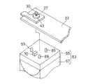
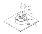
図11は、本発明の他の実施の形態のロータ治具243を示す斜視図であり、図12は、ロータ治具243を示す断面図である。ロータ治具243は、図3および図4に示すロータ治具43と類似しており、同様の構成ついては、説明を省略する。
【0144】
ロータ治具243は、軸線方向一端面201から突出する回転翼202が複数枚設けられる。回転翼202は、ロータ治具243の半径方向に延びる仮想半径線に対して対称に形成され、たとえば4枚形成される。各回転翼202は、軸線方向一端面201に対して、直角に屈曲し、半径方向に沿って延びる。
【0145】
ロータ治具243によって構成される軸垂測定装置は、図3および図4に示すコイル治具42を必要とせず、各回転翼202にエアー204を供給するノズル203が設けられる。ロータ治具243を軸受25に嵌め込んだ状態で、ノズル203から回転翼203に向けてエアーを供給することによって、ロータ治具243を回転させることができる。このようにロータ治具243と、ノズル203とによって、基準軸27を回転させる回転手段を軸垂測定装置が有してもよい。
【0146】
このような軸垂測定装置は、コイル治具42をベース22に固定する必要がないので、軸垂測定作業をより簡単に行うことができる。またノズル203を吹き付けてロータ治具243を回転させた状態で、ノズル203からエアーを供給することを停止し、慣性運動によって回転するロータ治具243において、軸垂測定を行うことが好ましい。これによって、ロータ治具243に負荷がかかることがなく安定した状態で、軸垂測定を行うことができ、より正確な軸垂測定を行うことができる。またノズル203から吹き付けられるエアーによって、ベース22上のロータ治具243まわりのゴミおよびほこりなどの付着物を取り除くことができる。
【0147】
また、慣性力によってロータ治具243が回転する状態で、軸受25の軸垂を求めるとともに、回転駆動力を停止した時からロータ治具243が停止するまでの時間を測定することによって、軸受25の損失トルクを調べることができる。これによって軸受25の軸垂を求めるとともに、損失トルクが大きい軸受を判別することができる。
【0148】
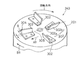
図13は、本発明のさらに他の実施の形態のロータ治具343を示す斜視図であり、図14は、ロータ治具343を示す斜視図である。ロータ治具343は、図11および図12に示すロータ治具243と類似しており、同様の構成については説明を省略し、同様の構成については、同様の符号をする。ロータ治具343は、軸線方向一端面201から突出する回転翼302が複数枚設けられる。
【0149】
回転翼302は、ロータ治具343の半径方向に延びる仮想半径線に対して、対称に形成され、たとえば4枚形成される。各回転翼302は、軸線方向一端面201に当接する当接部302aと、当接部302aから屈曲し、ロータ治具343の一端面201から突出する突出部302bとが形成される。
【0150】
突出部302bは、ロータ治具343の半径方向外方A1に進むにつれて、周方向一方B1に傾斜して立設される。周方向一方B1は、ロータ治具343回転方向と同方向であることが好ましい。さらに突出部302bは、軸線方向一端面201に対して90度より小さい所定の角度δを有して屈曲して形成される。また各回転翼302は、ロータ治具343の回転中心に対して、点対称に形成される。
【0151】
このように各回転翼302が形成されることによって、ロータ治具343の軸線方向他方側から軸線方向一端面201に向けて、たとえば上方からエアー204を吹き付けることによって、ロータ治具343を回転させることができる。突出部302bは、ロータ治具343の軸線方向一端面201から90度より小さい角度で立設しているので、回転翼302に吹き付けられたエアーは、突出部302bを回転方向に移動させる力を与え、これによってロータ治具343が回転する。また突出部302bは、ロータ治具343の半径方向外方A1に進むにつれて、周方向一方B1に傾斜して立設されるので、回転翼に吹き付けられたエアーを半径方向外方に移動しやすい。
【0152】
図13および図14に示すロータ治具343は、ノズル203によって、エアー204を供給することによって、ロータ治具343を回転させることができ、図11および図12に示すロータ治具243と同様の効果を得ることができる。さらに上方からエアー204を吹き付けることによって、ロータ治具343が軸受25に向かって押付けられ、ロータ治具343をより安定させて回転させることができる。
【0153】
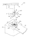
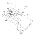
図15は、本発明のさらに他の実施の形態の軸垂測定装置420を示す斜視図である。図15に示す軸垂測定装置420は、図1に示す軸垂測定装置20と類似しており、同様の構成においては、説明を省略し同一の符号を付す。
【0154】
軸垂測定装置420は、ロータ治具443と、コイル治具42と、ノズル203と、高さ検出センサ401とを含んで構成される。高さ検出センサ401は、軸受25に嵌め込まれたロータ治具443の高さ位置を検出するセンサである。ロータ治具443は、半径方向外方に向かって突出する複数の回転翼403が設けられる。回転翼403は、ロータ治具軸線方向一方C1に進むにつれて、ロータ治具周方向一方D1に傾斜するエアー吹き付け面404が形成される。ロータ治具443は、軸受25に嵌め込まれ、ノズル203が下方から回転翼403に向けてエアー204を吹き付ける。エアー204はエアー吹き付け面404に当たり、ロータ治具443に回転力を与えることができる。
【0155】
軸垂測定装置420は、ベース22にコイル治具42が固定された状態で、ロータ治具443が軸受25に嵌め込まれる。エアー204が下方から吹き付けられることによって、ロータ治具443は、上方に向かって押し上げられる力をうける。このときロータ治具443が上方に変位する量を高さ検出センサ401によって測定することによって、ロータ治具443が上方に向かって押し上げられる力に抗する力を調べることができる。これによって軸垂測定対象となる軸受25がモータを構成した場合の、モータのロータのスラストバイアス力、すなわちモータ回転時にロータが浮き上がらないように軸受側に押さえつける力を推測することができる。また図15に示すロータ治具343は、ノズル203によって回転されるので、図11および図12に示すロータ治具243と同様の効果を得ることができる。
【0156】
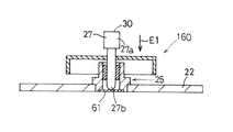
図16は、本発明の基準軸27が軸受25に嵌め込まれる部分の構造160を示す断面図である。ロータ治具は、基準軸27が圧入され、基準軸27が部分的にベース22に立設する軸受25に嵌め込まれる。基準軸27は、光が照射される一端部27aに対して反対側の他端部27b、すなわち軸受挿入方向E1下流側の端部27bが、先細に形成される。さらに具体的には、略半球状に形成され、軸受25の底板61と点接触する。これによって、基準軸27は、回転時に作用する摩擦力が少なくなり、回転時の負荷を低減することができ、基準軸27の回転を安定させることができる。このような基準軸27が圧入されたロータ治具は、回転手段によって回転される。回転手段は、電磁力によってロータを回転するステータを含んでもよく、またロータを回転させるための回転翼を含んでいてもよい。
【0157】
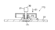
図17は、本発明の基準軸27が軸受25に嵌め込まれる部分の他の構造170を示す断面図である。図17に示す構造170は、図16に示す構造と類似しており、同様の構成については、説明を省略し、同一の符号を付す。軸受25のハウジング53内には、球体171が挿入される。軸受25に嵌め込まれた基準軸27は、その他端部27bが球体171に点接触する。これによって基準軸27は、回転時に作用する摩擦力が少なくなり、回転時の負荷を低減することができ、基準軸27の回転を安定させることができる。
【0158】
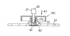
図18は、本発明の基準軸27が軸受25に嵌め込まれる部分のさらに他の構造180を示す断面図である。図18に示す構造180は、図16に示す構造と類似しており、同様の構成については、説明を省略し、同一の符号を付す。軸受25のハウジング53内には、複数の球体181が挿入される。複数の球体181は、軸受25の半径方向に並んで配置される。軸受25は、複数の球体181によって軸線26上を基準軸挿入方向E1に進むにつれて、窪む空間182が形成される。また基準軸27の他端部27bは、円錐状に形成される。軸受25に嵌め込まれた基準軸27は、各球体181と点接するピボットが形成される。これによって基準軸27は、回転時に作用する摩擦力が少なくなり、回転時の負荷を低減することができ、基準軸27の回転を安定させることができる。
【0159】
また、基準軸27の他端部27bに向かうにつれて、外径寸法が縮径するテーパが形成されてもよい。これによって、軸受の内周径と一致した部分で接触するので、軸受の内径に合わせてサイズの異なる基準軸27を用意する必要がない。
【0160】
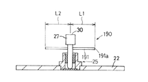
図19は、本発明のさらに他の回転手段を示す断面図である。ロータ治具に替えて、基準軸27に、基準軸27の回転軸線を挿通する棒状のピン部材191が設けられてもよい。ピン部材191は、基準軸27を貫通する。ピン部材191が基準軸27から一方側に突出する長さL1と他方側に突出する長さL2は、両側で等しい。ピン部材191の一端部191aを弾くことによって、基準軸27に回転力を与えて基準軸27を回転させる。このようにピン部材191を用いることによって、構造を簡略化することができる。また突出する長さが両側で等しいので、基準軸の回転を安定させることができる。本発明の軸垂測定装置は、このようなピン部材191を回転手段として用いることができ、他の回転手段以外の構成については、図1に示す軸垂測定装置と同様である。このような軸垂測定装置は、ピン部材191を弾く手段を有してもよい。または手動によってピン部材191を弾いてもよい。
【0161】
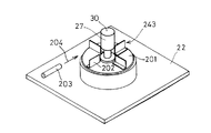
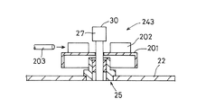
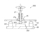
図20は、本発明のさらに他の回転手段200を示す断面図であり、図21は、回転手段200を示す斜視図である。ベース22に立設される軸受25が軸線方向両側に開放される筒状に形成される場合、基準軸27が軸受25を貫通する。回転手段200は、測定用モータ202を含んで構成される。測定用モータ202は、ベース22を乗載する乗載部65上に設けられる。測定用モータ202の出力軸203の遊端部には、マグネット201が設けられる。マグネット201は、軸受25を貫通する基準軸27の他端部27bに臨んで配置される。
【0162】
軸受25を貫通する基準軸27の他端部27bは、マグネット201に磁力によって吸着する。これによって基準軸27は、マグネット201を介して計測用モータ202の出力軸203に連結される。測定用モータ202を回転させることによって基準軸27を回転させることができる。これによって基準軸27と出力軸203とを一体的に固定する必要がなく、基準軸27と測定用モータの出力軸203との軸線が同一線上に配置させる必要がない。したがって基準軸27と出力軸203との軸合せを容易に行うことができる。本発明の軸垂測定装置は、このような測定用モータ202を回転手段として用いることができ、他の回転手段以外の構成については、図1に示す軸垂測定装置と同様である。
【0163】
図22は、本発明のさらに他のモータ521を示す分解斜視図である。モータ521は、図2に示すモータと類似しており同様の構成については、説明を省略し同一の符号を付す。モータ521は、ロータ537を有し、ロータ537は、マグネット35と、マグネット35を収容する円筒状のロータ体536を有する。ロータ537は、半径方向外方に向かって突出する複数の回転翼503が設けられる。回転翼503は、ロータ軸線方向一方C1に進むにつれて、ロータ周方向一方D1に向かうように傾斜するエアー吹き付け面504が形成される。エアー吹き付け面504にエアーが吹き付けられることによって、回転翼503は、ロータ周方向に回転する回転力が与えられる。
【0164】
図23は、本発明の他のモータ521の軸垂を測定する軸垂測定装置620を示す斜視図である。軸垂測定装置620は、モータ521の出力軸34の端面の傾きを測定するオートコリメータ44と、モータ521を回転させる回転手段とを含んで構成される。
【0165】
モータ521を回転する回転手段は、モータ521の回転翼503にエアー204を吹き付けてモータ521を回転するノズル203であってもよく、またステータのコイルを電通することによって、電磁的にモータ521を回転させる手段であってもよい。このようにモータ自体を回転させ、その出力軸34の傾きをオートコリメータ44によって測定することによって、出力軸34および軸受25の軸垂を測定することができる。
【0166】
また、ロータ537に回転翼503を設けることによって、モータ521回転時に、回転翼503がロータ周囲の空気を攪拌する。これによってステータ57のコイルによって加熱された周囲の空気がモータ近辺に留まることを防止し、モータ521に冷却機能を持たせることができる。回転翼503は、軸受25から遠ざかるにつれて、エアー吹き付け面504が周方向他方に向けて傾斜する。この周方向他方D2にロータ537を回転させることによって、回転翼503は、軸受25と反対方向に向かう気流を生じる。これによってロータ537に、軸受25に向かって押さえつけられるスラストバイアス力を与えることができる。スラストバイアス力が与えられたロータ537は、モータ軸線方向に変位することが防止され、回転不良を防止することができる。
【0167】
またノズル203によって、ロータ537を回転させて軸受25の軸垂を測定した場合、ロータ537に設けられるマグネット35によって発生する磁束が、ステータ57のコイルを通過することによって、コイルに誘起電圧が発生する。マグネット35に着磁不良がある場合には、マグネット35の着磁が正常に行われる場合に比べて誘起電圧が変動する。したがって、この誘起電圧を測定することによって、マグネット35の着磁不良を同時に調べることができる。
【0168】
上述の各構成は本発明の例示に過ぎず、発明の範囲内において構成を変更することができる。たとえば、基準軸27の一端面30の傾きを求めるために検出手段として、オートコリメータを用いたが、レーザ変位計を用いて基準軸の一端面30の傾きを求めてもよい。たとえばレーザ変位計を用いて、基準軸一端面30の3箇所を測定する。これによって、3箇所を結ぶ面を求めることができ、面の傾きを調べることができる。ベースに対して平行な2次元面内に投影される基準面に垂直な直線が描く閉ループの軌跡の重心を求めることによって、上述のように軸受25の軸垂を求めることができる。
【0169】
また、基準軸27またはロータ治具の重心が半径方向に偏って形成されてもよい。これによって、回転する基準軸7は遠心力が働き、重心に近い外周部分が、軸受25の内周面に当接するように力が働く。これによって基準軸27の少なくとも重心に近い外周部分を、軸受25の内周面に確実に当接させることができ、軸受内で基準軸27ががたつくことを防止し、内周面を確実にトレースすることができる。また、本発明の回転手段は、上述の記載に限定されず基準軸27を回転させる手段であればどのような構成であってもよい。また基準軸27を手動で回転させてもよい。
【0170】
【発明の効果】
以上のように本発明によれば、基準軸の軸径および基準軸の一端面の平面度に誤差があり、基準軸の形状がばらつくことがあっても、この基準軸の形状にかかわらず、正確な軸受の軸垂を測定することができる。したがって軸受の品質測定を確実に行うことができる。これによって、ベースに立設される軸受の良否を正確に判断することができ、品質の高い軸受を出荷することができる。
【0171】
また基準軸の誤差に軸垂測定値が影響しないので、精度の高い基準軸を製造する必要がなく、基準軸製造作業を容易にすることができる。さらに基準軸を軸受に嵌め込むときに基準軸の軸線が軸受軸線と同一線上に配置されるように精度よく配置する必要がなく、基準軸を軸受に嵌め込む作業を容易にすることができる。これによって短時間で基準軸を軸受に嵌め込むことができ、軸垂の測定に費やす時間を短縮することができる。
また、ロータに回転翼が設けられるので、回転翼に向かって気体を吹き付けることによって、回転翼とともにロータを軸受軸線まわりに回転させて、基準軸を回転させ軸受の軸垂を測定することができるとともにモータに冷却機能を持たせることができる。
【0180】
また本発明によれば、ロータに設けられる回転翼によって、スラストバイアス力を作用させることができるので、ロータが回転軸線方向に変位することが防止され、モータの回転不良を防止することができる。たとえば、軸垂測定対象をコンパクトディスク(CD)またはデジタルバーサタイルディスク(DVD)等の円板状記憶媒体を回転させるモータとして用いた場合に、回転軸線方向への変位を防止することによって、円盤状記憶媒体の浮き上がりを防止することができ、データの読み取り不良を防止することができる。
【図面の簡単な説明】
【図1】図1は、本発明の実施の一形態の軸受の軸垂測定装置20の一部を示し、図1(1)は、軸垂測定装置20の断面図であり、図1(2)は、軸垂測定時の表示画面を示す正面図である。
【図2】軸垂測定対象である軸受25が設けられるブラシレススピンドルモータ21を示す分解斜視図である。
【図3】軸垂測定装置20のロータ治具43付近を拡大して示す断面図である。
【図4】図4は、軸垂測定装置20のロータ治具43付近を示す斜視図である。
【図5】軸受25に嵌め込まれた基準軸27の状態を示す軸受部分の拡大断面図と、そのとき表示される表示画面49を示す正面図である。
【図6】軸受25に嵌め込まれた基準軸27の状態を示す軸受部分の拡大断面図と、その状態で表示される表示画面49を示す正面図である。
【図7】オートコリメータ44とベース22とを支持する支持台62を説明するための斜視図であり、図7(2)は乗載部65を示す斜視図であり、図7(3)は鏡面体64を示す斜視図である。
【図8】微動ステージを調整する前の状態であって、鏡面体70に入射光を照射したときの表示画面49を示す図である。
【図9】軸受25が立設されたベース22を乗載部65に乗載する状態を示す斜視図である。
【図10】軸受25の軸垂測定の手順を示すフローチャートである。
【図11】本発明の他の実施の形態のロータ治具243を示す斜視図である。
【図12】ロータ治具243を示す断面図である。
【図13】本発明のさらに他の実施の形態のロータ治具343を示す斜視図である。
【図14】ロータ治具343を示す斜視図である。
【図15】本発明のさらに他の実施の形態の軸垂測定装置420を示す斜視図である。
【図16】本発明の基準軸27が軸受25に嵌め込まれる部分の構造160を示す断面図である。
【図17】本発明の基準軸27が軸受25に嵌め込まれる部分の他の構造170を示す断面図である。
【図18】本発明の基準軸27が軸受25に嵌め込まれる部分のさらに他の構造180を示す断面図である。
【図19】本発明のさらに他の回転手段を示す断面図である。
【図20】本発明のさらに他の回転手段200を示す断面図である。
【図21】回転手段200を示す斜視図である。
【図22】本発明のさらに他のモータ521を示す分解斜視図である。
【図23】本発明の他のモータ521の軸垂を測定する軸垂測定装置620を示す斜視図である。
【図24】ベース2に立設するモータ1の主要部の概観を示す斜視図である。
【図25】軸受5の軸垂を測定するための基準軸7を示す斜視図である。
【図26】従来の技術の軸垂測定装置8の一部を示す斜視図である。
【図27】他の従来の技術の軸垂測定装置9の一部を示す斜視図である。
【図28】軸受5の軸線6に対して基準軸7の軸線がずれた場合を示す断面図である。
【図29】基準軸7の端面10が基準軸7の軸線11に垂直な仮想面12に対して傾斜して形成される場合を示す断面図である。
【符号の説明】
20 軸垂測定装置
21 スピンドルモータ
22 ベース
25 軸受
27 基準軸
30 基準軸の一端面
42 コイル治具
43 ロータ治具
44 オートコリメータ
49 表示画面
51 表示点
52 軌跡
[0001]
BACKGROUND OF THE INVENTION
  The present invention relates to a method for measuring the axis of a bearing.To the lawRelated.
[0002]
[Prior art]
FIG. 24 is a perspective view showing an overview of the main part of the motor 1 erected on the base 2. The quality of the motor 1 is affected by the angle θ of the rotating shaft 3 with respect to the base 2, and the inclination of the angle θ of the rotating shaft 3 is called axial droop. The axis suspension is an inclination of the rotation axis 4 of the motor 1 with respect to a vertical line perpendicular to the base 2. When the bearing itself erected on the base 2 is inclined with respect to the base 2, the rotating shaft 3 fitted into the bearing 5 is also inclined with respect to the base 2.
[0003]
Therefore, in the assembly process of the motor 1, it is an important management item to measure and manage the shaft suspension of the bearing 5 of the motor 1. For example, in a spindle motor for rotating a compact disk, the rotation axis 4 is suppressed to an inclination within a range of ± 0.13 degrees with respect to a vertical line perpendicular to the base 2.
[0004]
FIG. 25 is a perspective view showing the reference shaft 7 for measuring the shaft suspension of the bearing 5. In the prior art shaft measurement method, the reference shaft 7 is used to measure the bearing axis 6. In the conventional method for measuring the shaft, the reference shaft 7 is fitted into the bearing 5 and the reference shaft 7 is measured by measuring the inclination of the reference shaft 7 with respect to the base 2 while the reference shaft 7 and the base 2 are fixed. . In the prior art method of measuring the shaft suspension, the obtained shaft suspension of the reference shaft 7 is approximated as the shaft suspension of the bearing 5.
[0005]
FIG. 26 is a perspective view showing a part of a conventional vertical axis measuring apparatus 8. The prior art shaft measuring device 8 has a contact-type displacement sensor 9. The contact displacement sensor 9 scans the end surface 10 of the reference shaft 7 fitted in the bearing 5 in two horizontal directions X and Y. In this way, the inclination of the end surface 10 of the reference shaft 7 with respect to the base 2 is measured, and the vertical axis of the reference shaft 7 is obtained. The axis of the reference shaft 7 is approximated as the axis of the bearing 5.
[0006]
FIG. 27 is a perspective view showing a part of a shaft measuring apparatus 9 of another conventional technique. Another prior art bearing measuring device 9 measures the axis of the reference shaft 7 by a non-contact displacement sensor. The bearing measuring device 9 measures the inclination of the reference shaft one end surface 10 with respect to the base 2 by irradiating light toward the reference shaft one end surface 10 and receiving the light reflected from the one end surface 10. Find the axis of the axis. The axis of the reference shaft 7 is approximated as the axis of the bearing 5.
[0007]
An apparatus for measuring the runout of a shaft fitted in a bearing is disclosed. For example, a bearing manufacturing apparatus disclosed in Japanese Patent Application Laid-Open No. 2000-205857 measures the displacement of the outer peripheral surface of the rotor shaft by fitting the bearing into the rotor shaft for measurement and rotating the rotor shaft. In the nozzle inspection apparatus disclosed in Japanese Patent Application Laid-Open No. 9-79872, a monitor provided above the nozzle end face displays the runout of a rotating nozzle fitted in a bearing.
[0008]
[Problems to be solved by the invention]
In the prior art shaft measuring devices 8 and 9 shown in FIGS. 26 and 27, when there is a dimensional error in the reference shaft 7, the shaft suspension of the reference shaft 7 and the shaft shaft of the bearing 5 are not equal. The shaft axis cannot be approximated as a bearing axis.
[0009]
FIG. 28 is a cross-sectional view showing a case where the axis of the reference shaft 7 is deviated from the axis 6 of the bearing 5. When the outer diameter of the reference shaft 7 is formed smaller than the inner diameter of the bearing 5 due to a dimensional error of the reference shaft 7, the reference shaft 7 has an axis 11 of the reference shaft 7 that is opposite to the axis 6 of the bearing 5. There is a risk of slipping and fitting into the bearing 5. Further, if a gap is formed between the reference shaft 7 and the bearing 5 due to the dimensional tolerance of the reference shaft 7, there may be a case where the reference shaft 7 and the bearing 5 cannot be reliably fixed.
[0010]
When a deviation Φ1 occurs between the bearing 6 and the axis 6, the axis 6 of the bearing 5 does not match the axis 11 of the reference shaft 7. Therefore, the conventional vertical measuring devices 8 and 9 shown in FIGS. 26 and 27 can measure only the axis 11 of the reference shaft 7 and cannot measure the axis 6 of the true bearing 5.
[0011]
FIG. 29 is a cross-sectional view showing a case where the end surface 10 of the reference shaft 7 is formed to be inclined with respect to the virtual surface 12 perpendicular to the axis 11 of the reference shaft 7. As shown in FIG. 29, when the one end face 10 of the reference axis 7 is inclined with respect to the virtual plane 12, the reflected light of the light irradiated to the one end face 10 along the axis of the reference axis 7 is the reference axis. 7 is reflected off the axis 11.
[0012]
27 measures the axis of the reference axis 7 by the reflected light of the prior art, and therefore, between the reflected light and the axis 11 of the reference axis as shown in FIG. If there is a deviation Φ2, the axis 11 of the reference axis 7 cannot be measured. Therefore, the shaft sag of the bearing 5 cannot be obtained.
[0013]
Similarly, even in the device for measuring the runout of the shaft fitted in the bearing disclosed in Japanese Patent Laid-Open No. 2000-205857 and Japanese Patent Laid-Open No. 9-79872, there is a dimensional error in the shaft fitted in the bearing. However, it is not possible to measure the shaft suspension of the bearing.
[0014]
  Accordingly, an object of the present invention is to provide a bearing axis measuring method capable of measuring an accurate bearing axis regardless of the dimensional accuracy of the reference shaft.The lawIs to provide.
[0015]
[Means for Solving the Problems]
  The present invention is a method for measuring the shaft suspension of a bearing erected on a base,
  A reference shaft formed so as to be able to be fitted to the bearing is rotatably fitted in the bearing,
  Irradiating one end surface of the reference axis with light to detect reflected light, rotating the reference axis, and examining the rotation trajectory of the reflected light in a plane parallel to the base;
  Obtain the center of gravity of the rotation trajectory, and obtain the bearing shaft based on the center of gravity.,
  When forming the shaft measurement object as a motor including a rotor and a stator,
  A rotor provided with the reference shaft and the rotor blade is fitted into the bearing, and gas is blown onto the rotor blade to rotate the rotor so as to obtain the shaft suspension of the bearing.This is a bearing vertical measurement method characterized by the above.
[0016]
According to the present invention, the inclination of the bearing axis with respect to a vertical line perpendicular to the base can be measured. When there is no error in the dimension of the reference axis, the light irradiated to one end surface of the reference axis is reflected according to the inclination of the bearing axis with respect to the base. As the inclination of the bearing axis increases with respect to the vertical line perpendicular to the base, one end surface of the reference axis is inclined with respect to the base, and the light reflection angle increases. That is, when the irradiation light and the reflection light are projected on the two-dimensional plane, the distance from the irradiation light point to the reflection light point increases.
[0017]
When there is no error in the dimension of the reference axis, the reflected light spot projected on the two-dimensional plane is shown at one position regardless of the rotation of the reference axis, and is proportional to the inclination of the bearing axis. Therefore, by obtaining the reflected light spot, the inclination of the bearing axis, that is, the bearing axis can be calculated.
[0018]
Further, as shown in FIGS. 28 and 29, the reflected light spot projected on the two-dimensional plane may differ from the point projected on the two-dimensional plane due to the dimensional error of the reference axis. However, according to the present invention, the dimension of the reference axis is calculated by rotating the reference axis and calculating the bearing axis based on the center of gravity of the rotation locus of the reflected light projected on the two-dimensional plane parallel to the base. Regardless of the error, an accurate bearing shaft can be obtained.
[0019]
For example, as shown in FIG. 28, even if the bearing axis line and the axis line of the reference axis are shifted, by rotating the reference axis according to the present invention, the reference axis rotates around the bearing axis line. The end face also rotates around the bearing axis. For example, the reflected light projected on the two-dimensional surface draws a closed loop locus. As the deviation between the bearing axis and the reference axis decreases, the closed loop decreases toward its center of gravity and is determined by the bearing axis if there is no deviation between the bearing axis and the reference axis. Expressed in one point.
[0020]
Therefore, the rotational locus drawn by the point at which the reflected light is projected in the two-dimensional plane, for example, the center of gravity of the closed loop locus, is a position determined by the bearing axis regardless of the axis of the bearing axis and the axis of the reference axis. . Accordingly, by obtaining the position of the center of gravity of the rotation locus, it is possible to examine the exact inclination of the bearing axis excluding the influence of the error of the reference axis.
[0021]
Further, for example, as shown in FIG. 29, even when one end surface of the reference axis is not perpendicular to the reference axis line, similarly, the reflected light projected in the two-dimensional plane by rotating the reference axis is Draw a rotation trajectory. By obtaining the position of the center of gravity of the rotation locus, it is possible to examine the exact inclination of the bearing axis excluding the influence of the reference axis error.
[0022]
  Thus, even when the error in the outer diameter of the reference axis and the shape error in the end face are formed, the reference axis is rotated to draw a reflected light spot projected on a two-dimensional plane such as a plane parallel to the base. By obtaining the center of gravity of the locus of the rotation locus, a true bearing axis line can be obtained, and an accurate bearing shaft can be obtained.
  Further, in order to rotate the reference shaft, a rotor having rotating blades and provided with the reference shaft is used. By blowing the gas toward the rotor blades, the rotor can be rotated around the bearing axis along with the rotor blades, and the shaft droop of the bearing can be measured.
  When the rotor is configured as a part of the motor, the rotor blades agitate the air around the rotor. As a result, the ambient air heated by the stator coil can be prevented from staying in the vicinity of the motor, and the motor can have a cooling function.
[0040]
Further, the present invention is characterized in that when the rotor fitted in the bearing rotates, the rotor blades generate an airflow in a direction opposite to the bearing.
[0041]
According to the present invention, there is used a rotor blade that is formed so as to generate an airflow from the rotor blade in the direction opposite to the bearing when the rotor rotates. As a result, a thrust bias force pressed against the bearing can be applied to the rotor. The rotor on which the thrust bias force acts is prevented from being displaced in the direction of the rotation axis, and can prevent the rotation failure of the motor.
[0045]
Further, the present invention is characterized in that reflected light is detected by irradiating light to one end surface of the reference axis using an autocollimator during rotation of the reference axis.
[0046]
According to the present invention, by using an autocollimator, it is possible to detect reflected light satisfactorily by irradiating light to one end face of the reference axis.
[0075]
DETAILED DESCRIPTION OF THE INVENTION
FIG. 1 shows a part of a bearing apex measuring device 20 according to an embodiment of the present invention. FIG. 1 (1) is a cross-sectional view of the apical measuring device 20, and FIG. It is a front view which shows the display screen at the time of a shaft droop measurement. The shaft measuring device 20 is a device that measures the shaft hanging of the bearing 25 erected on the base 22. The axis of the bearing 25 is an angle at which the axis 26 of the bearing 25 is inclined with respect to a vertical line perpendicular to the base 22.
[0076]
The shaft measuring apparatus 20 includes a reference shaft 27, a rotating means 40, and an autocollimator 44 that is a displacement detecting means. The reference shaft 27 is formed so as to be fitted to the bearing 25. The reference shaft 27 has an outer diameter substantially equal to the inner diameter of the bearing 25, and the one axial end surface 30 is formed in a plane perpendicular to the axis 31 of the reference shaft 27. Further, the reference shaft one end surface 30 is a mirror surface. For example, the one end surface 30 is plated to become a mirror surface. Further, for example, a mirror is attached to the one end face 30.
[0077]
The one end surface 30 is a surface upstream of the reference shaft 27 in the bearing insertion direction. The reference shaft 27 has a larger outer diameter at the upstream end in the insertion direction than the end at the downstream in the insertion direction, and is formed in a two-stage cylindrical shape. The reference shaft 27 is formed on the outer peripheral portion with a resin having a low frictional resistance against a bearing 25 described later and softer than the metal of the bearing. For example, the surface of the reference shaft 27 is coated with acrylic or ABS resin (acrylonitrile / butadiene / styrene resin). Further, for example, the reference shaft 27 itself may be made of acrylic or ABS resin.
[0078]
The rotating means 40 drives the reference shaft 27 to rotate. The rotating means 40 is realized by, for example, a motor that rotates by electromagnetic force, and includes a rotor jig 43 and a coil jig 42. In the rotor jig 43, the reference shaft 27 is fitted to the measurement rotor body 41. The measuring rotor body 41 is formed in a bottomed cylindrical shape with one side opened. An insertion hole through which the reference shaft 27 is inserted is formed at the bottom of the measurement rotor body 41. The reference shaft 27 is press-fitted into the insertion hole. The axis of the press-fitted reference shaft 27 is provided on the same line as the axis of the measuring rotor body 41.
[0079]
The coil jig 42 is formed in a substantially cylindrical shape, and is fixed to the base 22 so as to surround the outer periphery of the bearing 25. The coil jig 42 has a core around which the coil 46 is wound. The coil jig 42 is connected to a power supply circuit 45 for supplying a current to the coil 46.
[0080]
The rotor jig 43 covers the coil jig 42 fixed to the base 22 in a state where the reference shaft 27 is fitted in the bearing 25. The rotor jig 43 is provided with a magnet 47 at a portion facing the coil jig 42. The rotating means 40 including the rotor jig 43 and the coil jig 42 rotates the rotor jig 43 around the bearing 25 when the coil 46 of the coil jig 42 is electrically connected.
[0081]
The autocollimator 44 irradiates one end surface 30 of the reference shaft 27 with light and detects reflected light reflected from the one end surface 30. The autocollimator 44 irradiates incident light toward the one end face 30 of the reference shaft 27 in a direction perpendicular to the base 22. Further, the autocollimator 44 measures the inclination of the one end face 30 of the reference shaft 27 that changes during rotation with respect to the base 22 and gives the measurement data to the display means 48.
[0082]
The display means 48 displays a point 51 where the reflected light is projected on a two-dimensional plane parallel to the base 22 based on the measurement data of the reflected light measured by the autocollimator 44. For example, the display means is realized including a CRT (Cathode Ray Tube) monitor.
[0083]
When the reference shaft one end face 30 is inclined with respect to the base 22, the display position 51 is shifted from the origin position 50 as indicated by a black dot in FIG. The display position 51 is displayed away from the origin position 50 as the reference axis one end face 30 is inclined with respect to the base 22.
[0084]
For example, as shown in FIG. 28, when the reference shaft 27 has a dimensional error, the inclination of the reference shaft one end surface 30 with respect to the base 22 changes with the rotation of the reference shaft 27. Specifically, when the reference shaft 27 is tilted with respect to the axis of the bearing 25, by rotating the reference shaft 27, the tilt with respect to the axis of the bearing 25 maintains the same angle, and the direction of the tilt is rotated. It changes cyclically. As a result, the inclination direction of the reference axis one end face 30 returns to the original inclination direction when the reference axis makes one revolution. Therefore, the display point 51 displayed on the display screen 49 also returns to the original position when the reference axis 27 rotates once. As described above, the display point 51 displayed on the display screen 49 is rotated by the reference axis 27, and the locus 52 draws a closed locus in the display screen. If a closed loop shape cannot be obtained, a pseudo closed loop may be obtained by averaging the curves of the rotation trajectories.
[0085]
FIG. 2 is an exploded perspective view showing the brushless spindle motor 21 provided with the bearing 25 that is the object of shaft measurement. The bearing 25 is erected from the base 22. The bearing 25 constitutes a part of a motor 21 that rotates a disk-shaped storage medium such as a compact disc (CD) or a digital versatile disc (DVD). The motor 21 needs to rotate the disk-shaped recording medium without shaking, and the output shaft 34 of the motor 21 preferably extends perpendicularly to the base 22. The allowable value of the inclination with respect to the vertical line extending perpendicularly to the base of the output shaft 34 is small, for example, manufactured with an inclination α within ± 0.13 degrees with respect to the vertical line. In order to manufacture the motor 21 that satisfies this allowable dimension, it is particularly necessary to accurately measure the shaft suspension of the bearing 25.
[0086]
The motor 21 includes a bearing 25, a core 57 constituting a stator, and a rotor 37. The core 57 has a coil wound around salient poles on which core sheets formed in a predetermined shape are stacked. The rotor 37 includes a magnet 35 and a rotor body 36 that houses the magnet 35. The magnet 35 is fixed to the inner peripheral surface of the rotor body 36.
[0087]
The bearing 25 is, for example, a sintered bearing. The sintered bearing includes a metal 54 that is formed in a cylindrical shape and contains a lubricating oil, and a housing 53 that covers the outer peripheral surface of the metal 54. When the output shaft 34 fitted in the metal 54 rotates, the lubricating oil impregnated in the metal 54 oozes between the output shaft 34 and the inner peripheral surface of the metal 54. As a result, the output shaft 34 can be smoothly rotated.
[0088]
The bearing 25, the core 57, the rotor 37, and the output shaft 34 are all formed on the same line. The core 57 covers the outer periphery of the bearing 25 and is fixed to the base 22. The rotor body 36 is formed with an insertion hole 38 that is inserted in the thickness direction. The output shaft 34 is press-fitted into the insertion hole 38. The motor is disposed at a position where the core 57 and the magnet face each other with a gap.
[0089]
FIG. 3 is an enlarged cross-sectional view showing the vicinity of the rotor jig 43 of the shaft droop measuring apparatus 20. FIG. 4 is a perspective view showing the vicinity of the rotor jig 43 of the shaft measuring device 20. The shaft suspension of the bearing 25 is measured in a state where the bearing 25 is fixed to the base 22. Therefore, before the core 57, the rotor 37 and the output shaft 34 shown in FIG. Since the axial suspension of the bearing 25 can be measured before assembling as the motor 21, only the normal bearing can be configured as the motor 21 by removing the bearing 25 exceeding the axial suspension allowable value.
[0090]
The housing 53 is provided in the axially one side A1 portion, and a base contact portion 58 that protrudes outward in the radial direction is formed. In addition, the housing 53 is connected to the base contact portion 58, and further protrudes from the base contact portion 58 to the one axial side A1, and is formed with a crimping piece 60 that is fitted radially inward from the base contact portion 58. . Further, a bottom plate 61 that closes one axial side A <b> 1 of the housing 25 is fitted into the inner peripheral surface of the crimping piece 60. A bifurcated portion 59 that is divided into two forks is formed at the tip of the crimping piece 60.
[0091]
The base contact portion 58 is in contact with the base 22 from one side A1 in the housing axial direction, and the crimping piece 60 is bent so that the bifurcated portion 59 opens to both sides in a state where the base piece 22 is inserted through the base 22 in the thickness direction. One bent portion of the bifurcated portion 59 contacts the base 22 from the other side A2 in the axial direction of the housing 53. As a result, the surface on one side A1 in the axial direction of the base contact portion 60 and the surface A2 on the other side in the axial direction of the bifurcated portion 59 cooperate to sandwich the base 22. As a result, the bearing 25 is fastened to the base 22.
[0092]
As described above, since the caulking piece 59 is caulked and fixed to the base 22 in the bearing 25, there is a possibility that the bearing axis line 26 may not be arranged perpendicular to the base 22. Therefore, it is necessary to accurately measure the shaft suspension of the bearing 25 and remove the bearing 25 whose shaft exceeds the allowable range.
[0093]
The shaft measuring apparatus 20 includes a rotor jig 43 and a coil jig 42 which are measurement jigs instead of the rotor 37 and the core 57 configured as the motor 21. The rotor jig 43 and the coil jig 42 are detachably formed on the base 22 and the bearing 25. As a result, the jigs 42 and 43 can be removed after the shaft 25 is measured, and the bearing 25 that falls within the allowable range of shaft can be advanced to the next process. By making the rotor jig 43 and the coil jig 42 similar to the core 57 and the rotor 37 constituting the motor shown in FIG. 2, it is possible to save the trouble of newly forming the jigs 43 and 42. .
[0094]
FIG. 5 shows an enlarged sectional view of the bearing portion showing the state of the reference shaft 27 fitted in the bearing 25 and a display screen 49 displayed at that time. In FIG. 5, the clockwise angle is negative, and the counterclockwise angle is positive.
[0095]
FIG. 5A shows a state in which the reference shaft 27 is formed without dimensional error and the bearing axis 26 extends perpendicularly to the base 22. FIG. 5 (2) shows a display screen in the state of FIG. 5 (1). When there is no dimensional error in the reference shaft 27, the reference shaft 27 fitted in the bearing 25 has its axis 31 extending on the same line as the bearing axis 26. Further, the one end face 30 of the reference shaft 27 is formed in a plane perpendicular to the axis 31 of the reference shaft 27. Therefore, the one end surface 30 of the reference shaft 27 fitted in the bearing 25 is arranged in parallel to the base 22 and becomes a surface perpendicular to the vertical line 74 perpendicular to the base 22.
[0096]
As described above, when the one end face 30 is parallel to the base 22, the reflected light 76 with respect to the incident light 75 irradiated by the autocollimator 44, that is, the reflected light 76 with respect to the incident light 75 incident perpendicularly to the base 22. Follows the same path as the incident light 75.
[0097]
Even if the reference shaft 27 rotates, the axis 31 of the reference shaft 27 and the bearing axis 26 are formed on the same line, so that the one end face 30 does not tilt with respect to the base 22. Therefore, the reflection direction of the reflected light 76 is constant regardless of the rotation of the reference shaft 27. As a result, the position of the reflected light 76 projected onto the two-dimensional surface 55 parallel to the base 22 is projected at a single position 51 regardless of the rotation of the reference axis 27.
[0098]
In the display screen 49 displayed by the display means 48, the position of the incident light 75 projected onto the two-dimensional plane 55 is the origin position 50, and the position of the reflected light 76 projected onto the two-dimensional plane 55 is the display point 51. . Therefore, as shown in FIG. 5 (1), when there is no error in the reference shaft 27 and the bearing 25 and the bearing axis 26 is perpendicular to the base 22, the display screen 49 is as shown in FIG. 5 (2). A display point 51 is displayed at a position equal to the origin position 50 in the display screen.
[0099]
Thus, when the display point 51 is displayed at one point of the origin position 50 regardless of the rotation of the reference shaft 27, the bearing axis 26 and the vertical line 74 perpendicular to the base 22 are equal, and the bearing axis 26 is the base. 22 is perpendicular.
[0100]
FIG. 5 (3) shows a state in which the outer diameter of the reference shaft 27 is formed smaller than the inner diameter of the bearing 25 and the bearing axis 26 extends perpendicularly to the base 22. FIG. 5 (4) shows a display screen in the state of FIG. 5 (3).
[0101]
When the outer diameter of the reference shaft 27 is smaller than the inner diameter of the bearing 25 due to a dimensional error of the reference shaft 27, the reference shaft 27 fitted into the bearing 25 is inclined with respect to the bearing axis 26. As a result, the one end face 30 of the reference shaft 27 is inclined with respect to a plane 77 perpendicular to the bearing axis 26. Since the bearing axis 26 extends perpendicularly to the base 22, for example, when the axis 31 of the reference shaft 27 is inclined by β degrees with respect to the bearing axis 26, the one end surface 30 of the reference shaft 27 is β degrees with respect to the base 22. Tilt.
[0102]
When the one end face 30 is inclined by β degrees with respect to the base 22, the reflected light 76 with respect to the incident light 75 is reflected with an inclination of 2β degrees from the incident light 75. Further, when the reference shaft 27 rotates, the axis 31 of the reference shaft 27 rotates around the bearing axis 26 and the inclination direction of the one end face 30 with respect to the base 22 changes. The reflected direction of the reflected light 76 changes with the rotation of the reference shaft 27. For example, the position where the reference shaft 27 at the position indicated by the solid line in FIG. 5 (3) is angularly displaced by 180 degrees around the bearing axis 26 is indicated by a two-dot chain line in FIG. 5 (3). The reflected light 176 at this time also moves 180 degrees around the bearing axis 26 and is reflected at an angle of 2β with respect to the incident light on the one end face 30. When the reference shaft 27 rotates once, the direction of the reflected light also rotates once and returns to the original position. Therefore, as shown in FIG. 5 (4), the display point 51 displayed on the display screen moves along a closed loop which is an example of a rotation locus. At this time, the display point 51 moves along a point where the bearing axis 26 is projected onto the two-dimensional surface 55, that is, along a closed loop including the origin position 50 therein.
[0103]
The reflected light moves around the bearing axis 26 as the reference shaft 27 rotates. When the inclination angle β of the axis 31 of the reference shaft 27 with respect to the bearing axis 26 becomes small, the state shown in FIG. 5A is approached and the closed loop becomes small. At this time, the closed loop becomes smaller toward the center of gravity of the closed loop. Therefore, the position of the center of gravity of the closed loop is determined according to the bearing axis 26 regardless of the inclination angle β. Therefore, by obtaining the center of gravity of the locus 52 by calculation, the shaft axis 26 and, in turn, the vertical axis of the bearing 25 can be obtained. As a result, even if the reference shaft 27 is fitted to the bearing 25 in a state where the reference shaft 27 is displaced from the bearing axis 26, the shaft suspension of the bearing 25 can be obtained.
[0104]
FIG. 5 (5) shows a state in which one end face 30 of the reference shaft 27 is formed to be inclined with respect to a plane perpendicular to the axis 31 of the reference axis, and the bearing axis 26 extends perpendicular to the base 22. FIG. 5 (6) shows a display screen in the state of FIG. 5 (5).
[0105]
When the one end surface 30 of the reference shaft 27 is formed to be inclined with respect to the surface 73 perpendicular to the axis 31 of the reference shaft 27, the one end surface 30 of the reference shaft 27 fitted into the bearing 25 is the bearing axis 26. Tilt relative to a plane perpendicular to. When the bearing axis 26 extends perpendicularly to the base 22 and, for example, the one end surface 30 of the reference shaft 27 is inclined by γ degrees with respect to the surface 73 perpendicular to the reference shaft 27, the one end surface 30 of the reference shaft 27 is It is inclined by γ degrees.
[0106]
When the one end face 30 is inclined by γ degrees with respect to the base 22, the reflected light 76 is reflected with an inclination of 2γ degrees with respect to the incident light 75. Further, when the reference shaft 27 rotates, the one end surface 30 of the reference shaft 27 rotates around the axis of the bearing 25. Therefore, as in FIG. 5 (3), the reflected direction of the reflected light 76 changes as the reference shaft 27 rotates. As a result, the locus 52 of the reflected light 76 projected onto the two-dimensional surface 55 parallel to the base 22 moves along the closed loop. At this time, the display point 51 moves along a point where the bearing axis 26 is projected onto the two-dimensional surface 55, that is, along a closed loop including the origin position 50 therein.
[0107]
As the reference shaft 27 rotates, it moves around the bearing axis 26. When the inclination angle γ of the end surface 30 of the reference shaft 27 with respect to the axis 31 of the reference shaft 27 decreases, the state shown in FIG. 5A is approached and the closed loop is reduced. At this time, the closed loop becomes smaller toward the center of gravity of the closed loop. Therefore, the position of the center of gravity of the closed loop is determined according to the bearing axis 26 regardless of the inclination angle γ. Therefore, by obtaining the center of gravity of the locus 52 by calculation, the shaft axis 26 and, in turn, the vertical axis of the bearing 25 can be obtained. As a result, even if the one end surface 30 of the reference shaft 27 is inclined with respect to the surface perpendicular to the axis 31 of the reference shaft 27, the axial suspension of the bearing 25 can be obtained.
[0108]
FIG. 6 shows an enlarged cross-sectional view of the bearing portion showing the state of the reference shaft 27 fitted in the bearing 25, and a display screen 49 displayed in that state. In FIG. It shows a state in which the bearing axis 26 is tilted with respect to a vertical line 74 that is formed without error and extends perpendicularly to the base 22. FIG. 6B shows the display screen in the state of FIG. In FIG. 6, the clockwise angle is negative, and the counterclockwise angle is positive.
[0109]
When there is no dimensional error of the reference shaft 27, the reference shaft 27 fitted into the bearing 25 has its axis 31 extending on the same line as the bearing axis 26. One end face 30 of the reference shaft 27 is formed in a plane perpendicular to the axis 31 of the reference shaft 27. For example, if the bearing axis 26 is inclined by σ degrees with respect to a vertical line 74 perpendicular to the base 22, the one end surface 30 of the reference shaft 27 fitted into the bearing 25 is in relation to a surface 77 parallel to the base 22. The surface is inclined by σ degrees.
[0110]
Since the one end face 30 is inclined σ degrees with respect to the base 22 in this way, the reflected light 76 with respect to the incident light 75 irradiated in the direction perpendicular to the base 22 is reflected with an inclination of 2σ degrees from the incident light 75. Even if the reference shaft 27 rotates, the axis 31 of the reference shaft 27 and the bearing axis 26 are formed on the same line, so that the inclination of the one end face 30 with respect to the base 22 does not change. Therefore, the reflection direction of the reflected light 76 is constant regardless of the rotation of the reference shaft 27. As a result, the position of the reflected light 76 projected onto the two-dimensional surface 55 parallel to the base 22 is projected at a single point regardless of the rotation of the reference axis 27.
[0111]
Therefore, as shown in FIG. 6B, when there is no error in the reference shaft 27 and the bearing 25 and the bearing axis 26 is inclined with respect to the vertical line 74 perpendicular to the base, the display screen 49 is displayed on the display screen. A display point 51 is displayed at one point deviated from the origin position 50. This amount of deviation is twice the angle σ at which the bearing axis 26 tilts with respect to the vertical line 74 perpendicular to the base 22. By measuring this deviation amount, the inclination of the bearing axis 26 can be known, and thereby the axis of the bearing 25 can be obtained.
[0112]
FIG. 6 (3) shows a state in which the outer diameter of the reference shaft 27 is smaller than the inner diameter of the bearing 25 and the bearing axis 26 is inclined with respect to a vertical line 74 extending perpendicularly to the base 22. FIG. 6 (4) shows a display screen in the state of FIG. 6 (3).
[0113]
When the outer diameter of the reference shaft 27 is formed smaller than the inner diameter of the bearing 25, the reference shaft 27 fitted in the bearing 25 has an axis 31 inclined with respect to the bearing axis 26, for example, β degrees. In FIG. 6, β tilts clockwise and becomes a negative value. Further, for example, the bearing axis 26 is inclined σ degrees with respect to a vertical line 74 extending perpendicularly to the base 22. In FIG. 6, σ tilts counterclockwise and is a positive value. As described above, when the axis 31 of the reference shaft 27 is inclined with respect to the bearing axis 26 and the bearing axis 26 is inclined with respect to the vertical line 74 perpendicular to the base 22, the reference shaft fitted into the bearing 25 is used. The one end surface 30 of 27 is inclined with respect to a surface 77 parallel to the base 22, and the inclination changes with the rotation of the reference shaft 27.
[0114]
For example, in FIG. 6 (3), the reference axis 27 that is most angularly displaced counterclockwise at a point perpendicular to the paper surface is indicated by a solid line, and one end face 30 of the reference axis 27 in this state is Tilt (σ + β) degrees. In FIG. 6, since β is a negative value and | β |> | σ |, the one end surface 30 is counterclockwise (| β | −σ) degrees with respect to the surface 77 parallel to the base. Tilt.
[0115]
Therefore, the reflected light 76 with respect to the incident light 75 irradiated in the direction perpendicular to the base 22 is reflected with an inclination of 2 (σ + β) degrees from the incident light 75. In FIG. 6, the reflected light is reflected in a direction inclined by 2 (| β | -σ) degrees counterclockwise with respect to the incident light.
[0116]
When the reference shaft 27 rotates, the axis 31 of the reference shaft 27 rotates around the bearing axis 26, and the one end surface 30 of the reference shaft 27 also rotates around the bearing axis 26. Therefore, the reflection direction of the reflected light 76 changes as the reference shaft 27 rotates. For example, when the reference shaft 27 is displaced by 180 degrees around the bearing axis 26, the reference shaft 27 moves to the position indicated by the two-dot chain line in FIG. 5 (3) and is tilted most counterclockwise with respect to the base 22. It becomes a state. At this time, the one end face 30 of the reference shaft 27 is inclined (σ−β) degrees with respect to the base 22. In FIG. 6, since β is a negative value, the one end surface 30 is inclined (σ + | β |) degrees clockwise with respect to the surface 77 parallel to the base. The reflected light 176 at this time is reflected by being inclined by 2 (σ−β) degrees from the incident light 75 while being displaced by 180 degrees around the bearing axis 26 from the direction indicated by the solid line in FIG. In FIG. 6, the reflected light is reflected in a direction inclined by 2 (σ + | β |) degrees counterclockwise with respect to the incident light.
[0117]
The reflected light rotates between 2 (σ + β) degrees and 2 (σ−β) degrees with respect to the incident light. Therefore, the reflected light always includes an angle 2σ that is twice the angle σ at which the bearing axis 26 tilts with respect to the vertical line 74 perpendicular to the base 22 and rotates around the incident light. That is, the reflected light moves around an axis perpendicular point 78 that extends at an angle 2σ that is twice the angle σ at which the bearing axis 26 is inclined from the point with respect to the incident light.
[0118]
As the angle σ of the bearing axis 26 with respect to the vertical line 74 perpendicular to the base 22 increases, the closed loop deforms from a perfect circle to an ellipse. However, since the bearing 25 to be measured for the vertical axis has a small inclination angle σ with respect to the vertical line 74 whose axis 26 is perpendicular to the base 22, the closed loop has a shape close to a perfect circle. When the inclination angle β of the axis 31 of the reference shaft 27 with respect to the bearing axis 26 is zero, the state shown in FIG. As the angle β of the axis 31 of the reference shaft 27 with respect to the bearing axis 26 increases, the closed loop including the axis perpendicular point 78 increases.
[0119]
As a result, as shown in FIG. 6 (4), on the display screen 49, an axis perpendicular point 78 is formed at substantially the center of gravity of the closed loop locus 52. Therefore, by rotating the reference axis 27, the closed loop-like locus 52 drawn by the point where the reflected light is projected onto the two-dimensional surface 55 is measured, and the center of gravity of the locus 52 can be approximated to obtain the axis perpendicular point 78. . By obtaining the shaft perpendicular point 78, the angle σ of the bearing axis 26 with respect to the vertical line 74 perpendicular to the base 22, that is, the shaft perpendicular can be obtained. Further, even if the axis 31 of the reference shaft 27 is inclined by β degrees with respect to the bearing axis 26, it is possible to determine the exact axis of the bearing 25 by determining the position of the center of gravity of the locus 52 of the closed loop.
[0120]
FIG. 6 (5) shows a state where one end face 30 of the reference shaft 27 is inclined with respect to a plane perpendicular to the axis 31 of the reference axis, and the bearing axis 26 extends perpendicularly to the base 22. FIG. 6 (6) shows a display screen in the state of FIG. 6 (5).
[0121]
When the one end surface 30 of the reference shaft 27 is formed to be inclined with respect to the surface 73 perpendicular to the axis 31 of the reference shaft 27, the one end surface 30 of the reference shaft 27 fitted into the bearing 25 is the bearing axis 26. It is inclined with respect to the plane 73 perpendicular to the angle, for example, γ degrees. In FIG. 6, γ is a negative value. Further, for example, the bearing axis 26 is inclined σ degrees with respect to a vertical line 74 extending perpendicularly to the base 22. In FIG. 6, σ is a positive value. As described above, when the one end face 30 of the reference shaft 27 is inclined with respect to the axis 31 of the reference shaft 27 and the bearing axis 26 is inclined with respect to the vertical line 74 perpendicular to the base 22, the reference shaft 27 is fitted into the bearing 25. The one end face 30 of the reference shaft 27 is inclined with respect to the base 22, and the inclination changes as the reference shaft 27 rotates.
[0122]
For example, the reference axis 27 in the state of the most angular displacement in the clockwise direction at a point perpendicular to the paper surface of FIG. Tilted by (σ + γ) degrees. In FIG. 6, γ is a negative value and | γ |> | σ |, so that the one end face 30 is (| γ | −σ) degrees counterclockwise with respect to the plane 77 parallel to the base. Tilt.
[0123]
Accordingly, the reflected light 76 with respect to the incident light 75 irradiated in the direction perpendicular to the base 22 is reflected with an inclination of 2 (γ + σ) degrees from the incident light 75. In FIG. 6, the reflected light is reflected in a direction inclined by 2 (| γ | −σ) degrees counterclockwise with respect to the incident light.
[0124]
When the reference shaft 27 rotates, the axis 31 of the reference shaft 27 rotates around the bearing axis 26, and the one end surface 30 of the reference shaft 27 also rotates around the bearing axis 26. Therefore, the reflection direction of the reflected light 76 changes as the reference shaft 27 rotates. For example, when the reference shaft 27 is displaced by 180 degrees around the bearing axis 26, the reference shaft 27 moves to the position indicated by the two-dot chain line in FIG. It becomes a state. At this time, the one end face 30 of the reference shaft 27 is inclined (σ−γ) degrees with respect to the base 22. In FIG. 6, since γ is a negative value, the one end surface 30 is inclined (σ + | γ |) degrees clockwise with respect to the surface 77 parallel to the base 22. The reflected light 176 at this time is reflected by being tilted by 2 (σ−γ) degrees from the incident light 75 while being displaced by 180 degrees around the bearing axis 26 from the direction indicated by the solid line in FIG. In FIG. 6, the reflected light is reflected in a direction inclined by 2 (σ + | γ |) degrees counterclockwise with respect to the incident light.
[0125]
The reflected light rotates between 2 (σ + β) degrees and 2 (σ−β) degrees with respect to the incident light. Therefore, the reflected light always includes an angle 2σ that is twice the angle σ at which the bearing axis 26 tilts with respect to the vertical line 74 perpendicular to the base 22 and rotates around the incident light. In other words, the point of the reflected light 76 projected onto the two-dimensional surface 55 parallel to the base 22 moves along a closed loop including the point where the bearing axis 26 is projected onto the two-dimensional surface 55. That is, with respect to the incident light, the reflected light rotates around an axis perpendicular point 78 that extends at an angle 2σ that is twice the angle σ at which the bearing axis 26 tilts from the point, and is projected onto the two-dimensional plane 55.
[0126]
Similar to the description of FIGS. 6 (4) and 6 (5), on the display screen 49, the closed-loop locus 52 is formed in a substantially circular shape, and an axis perpendicular point 78 is formed at the center of gravity. Therefore, by rotating the reference axis 27 as described above, the closed loop locus 52 drawn by the point where the reflected light is projected in the two-dimensional plane is measured, and the center of gravity of the locus 52 is obtained by calculating the center of gravity. Can be sought.
[0127]
As a result, the angle σ of the bearing axis 26 with respect to the vertical line 74 perpendicular to the base 22, that is, the vertical axis can be obtained. Further, even if one end surface 30 of the reference shaft 27 is inclined by γ degrees with respect to a surface perpendicular to the axis 31 of the reference shaft 27, the accurate vertical axis of the bearing 25 can be obtained by obtaining the position of the center of gravity of the closed loop locus 52. Can be sought. Further, the locus of the reflected light does not necessarily have to be a closed loop locus. For example, as the reflected light rotates, even if the rotation locus shifts and a complete closed loop is not drawn, the image processing means provided in the autocollimator 44 or the display means 48 uses the rotation locus as a closed loop rotation locus. By approximating, the axial suspension of the bearing 25 can be obtained based on the approximated closed loop trajectory.
[0128]
FIG. 7 is a perspective view for explaining the support base 62 that supports the autocollimator 44 and the base 22, FIG. 7 (2) is a perspective view showing the mounting portion 65, and FIG. It is a perspective view which shows the mirror surface body 64. FIG. The shaft measurement apparatus 20 includes a support base 62 that supports the autocollimator 44 and the base 22.
[0129]
The support base 62 includes a fine movement stage 63 on which the base 22 is mounted, a mirror body 64 used for position adjustment of the fine movement stage 63 and the autocollimator 44, an autocollimator holding section 68 that holds the autocollimator 44, and a fine movement stage. 63 and a base portion 72 that supports the autocollimator holding portion 68.
[0130]
The fine movement stage 63 has a mounting portion 65 on which the base 22 is mounted, a first fine movement portion 66 that angularly displaces the mounting portion 65 about a first direction X extending along the horizontal direction, and extends along the horizontal direction. And a second fine movement portion 67 that angularly displaces the mounting portion 65 around a second direction Y that is orthogonal to the first direction X. The mounting portion 65 is provided with three support pieces 69 projecting upward and a magnet base 70. The base 22 abuts on the three support pieces 69, and the base 22 is mounted on the mounting portion 65. In a state where the base 22 is mounted, the magnet base 70 attracts the base 22 by a magnetic force, thereby preventing the base 22 from being displaced at the time of measuring the shaft and securely fixing it on the three support pieces 69.
[0131]
Further, fine movement stage 63 has a first direction X that is a direction along a plane perpendicular to the rotation axis of the reference axis, and a second direction Y that is a direction along a plane perpendicular to the rotation axis of the reference axis and is orthogonal to the first direction. A moving means for moving the base 22 is provided. For example, fine movement stage 63 is fitted in guide grooves 72 a and 72 b formed in base portion 72. The guide grooves 72a and 72b are formed in the first direction X and the second direction Y. As a result, fine movement stage 63 moves in parallel along first direction X and second direction Y. As a result, the base 22 and the mirror body 64 can be attached and detached while the fine movement stage 63 is moved from the measurement position. The measuring device such as the autocollimator 44 can easily perform the work without hindering the work of attaching and removing the base 22.
[0132]
The autocollimator 44 is held by an autocollimator holding unit 68. The autocollimator 44 is disposed above the base 22 mounted on the fine movement stage 63, and irradiates light onto one end face 30 of the reference shaft 27 attached on the base 22 from above, and measures reflected light. The mirror surface body 64 is formed in a short cylindrical shape, the thickness thereof is uniformly formed, and both surfaces in the thickness direction are formed flat. Further, the surface on one side in the thickness direction of the mirror body 64 is formed as a mirror surface.
[0133]
8 is a view showing a display screen 49 when the mirror surface 70 is irradiated with incident light before the fine movement stage is adjusted, and FIG. 9 shows the base 22 on which the bearing 25 is erected. FIG. 10 is a perspective view illustrating a state of being mounted on the mounting portion 65, and FIG. 10 is a flowchart illustrating a procedure for measuring the axis of the bearing 25. Hereinafter, with reference to FIG. 7 to FIG.
[0134]
As a procedure for measuring the axis of the bearing 25, first, as shown in FIG. 7A, in step s1, the mirror surface 64 is mounted on the three support pieces 69 with the mirror surface 71 of the mirror body 70 facing upward. A body riding operation is performed. When the mirror body mounting operation is completed, the process proceeds to step s2. In step s 2, a display point display operation is performed in which the autocollimator 44 irradiates light toward the mirror surface 71 of the mirror body 70, measures the reflected light reflected, and displays the reflected light on the display means 48. When the incident light travel direction is not perpendicular to the mirror surface 71 of the mirror body 70, the display point 51 is shifted from the origin position 50 as shown in FIG. 8. In step s3, it is determined whether or not the display point 51 displayed on the display screen 49 in step s2 is at the origin position 50. If the display point 51 is at the origin position 50, the process proceeds to step s5. Advances to step s4.
[0135]
In step s4, the first fine movement portion 66 and the second fine movement portion 67 of the fine movement stage 63 are angularly displaced around the first direction X and the second direction Y by the first fine movement portion 66 and the display displayed on the display screen 49. An adjustment operation for moving the point 51 to the origin position 50 is performed. By moving the display point 51 to the origin position 50, the mirror body 64 can be disposed on a plane perpendicular to the direction in which the incident light travels. When the adjustment operation is completed, the process proceeds to step s5.
[0136]
In step s5, the mirror body 64 is first removed from the mounting portion 65, then the rotor jig 43 and the coil jig 42 are provided on the base 22 on which the bearing 25 is erected, and then mounted as shown in FIG. A base mounting operation for mounting the base 22 on the portion 65 is performed. The base 22 mounted on the mounting unit 65 is fixed to the mounting unit 65 by the magnet base 70. When the fixing is completed, the process proceeds to step s6. The base 22 having a uniform thickness mounted on the support piece 69 is arranged perpendicular to the incident light.
[0137]
In step s 6, the reference shaft 27 fitted into the bearing 25 is rotated from the autocollimator 44, light is incident on one end face 30 of the reference shaft 27, the reflected light is measured, and the reflected light is two-dimensionally displayed on the display screen 49. A measurement operation for displaying the locus 52 of the point projected in the plane is performed. When the base 22 and the one end face 30 of the reference shaft 27 are parallel, the display position 51 of the display screen 49 is displayed at the origin position 50. When the one end face 30 of the reference shaft 27 is inclined with respect to the base 22, the display position 51 of the display screen 49 is displayed with a deviation from the origin position 50. The display position 51 is displayed farther from the origin position 50 as the inclination of the one end face 30 of the reference axis 27 is larger. When the closed loop locus 52 is obtained in step s5, the process proceeds to step s7.
[0138]
In step s7, the position of the center of gravity of the closed loop locus 52 is obtained, and a calculation operation for approximating the position of the center of gravity with the bearing axis 26 is performed. When the calculation operation is completed, the process proceeds to step s8, and the shaft vertical measurement operation is completed To do.
[0139]
As described above, according to the axial measurement apparatus of the present embodiment, the reference shaft 27 is rotated and the change in the inclination of the reference shaft one end surface 30 with respect to the base is examined, regardless of the dimensional accuracy of the reference shaft 27. Therefore, it is possible to obtain an accurate shaft suspension of the bearing 25. Specifically, incident light perpendicular to the base 22 is irradiated onto the reference axis 27, and the locus 52 of the point at which the reflected light is projected onto the two-dimensional surface 55 parallel to the base 22 is measured. The locus 52 of the points projected in the two-dimensional plane becomes a rotation locus, and the center of gravity position of this rotation locus is obtained. The position of the center of gravity is determined by the inclination σ of the bearing axis, and is independent of the error of the reference shaft 27. Therefore, by examining the position of the center of gravity, it is possible to obtain the inclination σ of the bearing itself from which the error of the reference axis is removed, that is, the vertical axis. Further, since the one end face 30 of the reference shaft 27 is measured in a non-contact manner by light, the inclination of the one end face 30 of the minute reference shaft 27 can be measured.
[0140]
Further, by using a coil jig 42 and a rotor jig 43 similar to the configurations of the stator 37 and the rotor 57 of the motor, the jigs 42 and 43 can be formed by improving the stator 37 and the rotor 57. it can.
[0141]
Further, the axial measurement apparatus 20 may be configured to include an image processing unit that measures a closed loop locus 52 in a two-dimensional plane by image processing and calculates the center of gravity of the closed loop. Thus, the measurer can easily determine whether the bearing 25 is suspended, and can determine in a short time whether the bearing 25 is erected on the base 22. Further, the image processing means determines whether or not the measured shaft suspension of the bearing 25 is within a predetermined shaft suspension range based on the position of the center of gravity of the closed loop. Can be determined.
[0142]
Since the one end face 30 of the reference shaft 27 is formed in a mirror surface, the reflected light is not scattered and can be reflected in a straight line. Thus, an accurate reflection angle can be obtained. Further, since a resin softer than the metal 54 is provided on the outer peripheral portion where the reference shaft 27 will come into contact with the bearing, the reference shaft 27 does not damage the metal 54. Further, by using a resin having a low frictional resistance with respect to the bearing 25, it is possible to reduce the load when the reference shaft 27 is fitted and taken out. Further, since the reference shaft 27 is formed so that the outer diameter of the one end face 30 is larger than that of the other end face, even when the irradiated light deviates from the axis of the reference axis, it can be reliably reflected.
[0143]
FIG. 11 is a perspective view showing a rotor jig 243 according to another embodiment of the present invention, and FIG. 12 is a cross-sectional view showing the rotor jig 243. The rotor jig 243 is similar to the rotor jig 43 shown in FIGS. 3 and 4, and the description of the same configuration is omitted.
[0144]
The rotor jig 243 is provided with a plurality of rotating blades 202 protruding from the axial end surface 201. The rotor blades 202 are formed symmetrically with respect to a virtual radius line extending in the radial direction of the rotor jig 243, for example, four. Each rotary blade 202 bends at right angles to the axial end surface 201 and extends along the radial direction.
[0145]
The axial measurement apparatus constituted by the rotor jig 243 does not require the coil jig 42 shown in FIGS. 3 and 4, and is provided with a nozzle 203 that supplies air 204 to each rotary blade 202. With the rotor jig 243 fitted into the bearing 25, the rotor jig 243 can be rotated by supplying air from the nozzle 203 toward the rotary blade 203. As described above, the shaft measuring device may have a rotating means for rotating the reference shaft 27 by the rotor jig 243 and the nozzle 203.
[0146]
Such an axis measuring device does not require the coil jig 42 to be fixed to the base 22, so that the axis measuring operation can be performed more easily. In addition, in a state where the nozzle 203 is blown and the rotor jig 243 is rotated, the supply of air from the nozzle 203 is stopped, and it is preferable to perform axial measurement in the rotor jig 243 that rotates by inertial motion. As a result, the axial measurement can be performed in a stable state without applying a load to the rotor jig 243, and more accurate axial measurement can be performed. Further, the air blown from the nozzle 203 can remove foreign matters such as dust and dust around the rotor jig 243 on the base 22.
[0147]
Further, the bearing 25 is obtained by obtaining the shaft suspension of the bearing 25 while the rotor jig 243 is rotated by the inertial force, and measuring the time from when the rotational driving force is stopped until the rotor jig 243 is stopped. The torque loss can be examined. As a result, the shaft suspension of the bearing 25 can be obtained, and a bearing having a large loss torque can be determined.
[0148]
FIG. 13 is a perspective view showing a rotor jig 343 according to still another embodiment of the present invention, and FIG. 14 is a perspective view showing the rotor jig 343. The rotor jig 343 is similar to the rotor jig 243 shown in FIGS. 11 and 12, and the description of the same configuration is omitted, and the same configuration is denoted by the same reference numeral. The rotor jig 343 is provided with a plurality of rotating blades 302 protruding from the one end surface 201 in the axial direction.
[0149]
The rotor blades 302 are formed symmetrically with respect to a virtual radius line extending in the radial direction of the rotor jig 343, and, for example, four rotor blades 302 are formed. Each rotary blade 302 is formed with an abutting portion 302 a that abuts on one end surface 201 in the axial direction and a protruding portion 302 b that is bent from the abutting portion 302 a and projects from the one end surface 201 of the rotor jig 343.
[0150]
The protrusion 302b is erected so as to incline in one circumferential direction B1 as the rotor jig 343 moves outward in the radial direction A1. One circumferential direction B1 is preferably in the same direction as the rotation direction of the rotor jig 343. Furthermore, the protruding portion 302b is formed to be bent with a predetermined angle δ smaller than 90 degrees with respect to the axial end surface 201. Each rotary blade 302 is formed point-symmetrically with respect to the rotation center of the rotor jig 343.
[0151]
By forming each rotor blade 302 in this way, the rotor jig 343 is rotated by blowing air 204 from above, for example, toward the one axial end face 201 from the other axial side of the rotor jig 343. be able to. Since the protrusion 302b is erected at an angle smaller than 90 degrees from the axial end surface 201 of the rotor jig 343, the air blown to the rotary blade 302 has a force to move the protrusion 302b in the rotation direction. As a result, the rotor jig 343 rotates. Further, the protrusion 302b is erected so as to incline in the circumferential direction one B1 as the rotor jig 343 moves in the radially outward direction A1, so that the air blown to the rotor blades can easily move outward in the radial direction. .
[0152]
The rotor jig 343 shown in FIGS. 13 and 14 can rotate the rotor jig 343 by supplying air 204 through the nozzle 203, and is similar to the rotor jig 243 shown in FIGS. An effect can be obtained. Further, by blowing air 204 from above, the rotor jig 343 is pressed toward the bearing 25, and the rotor jig 343 can be rotated more stably.
[0153]
FIG. 15 is a perspective view showing an axial measurement apparatus 420 according to still another embodiment of the present invention. The axial measurement device 420 shown in FIG. 15 is similar to the axial measurement device 20 shown in FIG. 1, and in the same configuration, the description is omitted and the same reference numerals are given.
[0154]
The shaft measurement device 420 includes a rotor jig 443, a coil jig 42, a nozzle 203, and a height detection sensor 401. The height detection sensor 401 is a sensor that detects the height position of the rotor jig 443 fitted in the bearing 25. The rotor jig 443 is provided with a plurality of rotating blades 403 protruding outward in the radial direction. The rotor blade 403 has an air blowing surface 404 that is inclined in the rotor jig circumferential direction D1 as it proceeds in the rotor jig axial direction C1. The rotor jig 443 is fitted into the bearing 25, and the nozzle 203 blows air 204 toward the rotary blade 403 from below. The air 204 hits the air blowing surface 404 and can apply a rotational force to the rotor jig 443.
[0155]
In the axial measurement device 420, the rotor jig 443 is fitted into the bearing 25 in a state where the coil jig 42 is fixed to the base 22. When the air 204 is blown from below, the rotor jig 443 receives a force pushed upward. At this time, by measuring the amount by which the rotor jig 443 is displaced upward by the height detection sensor 401, it is possible to check the force against the force by which the rotor jig 443 is pushed upward. This makes it possible to estimate the thrust bias force of the rotor of the motor, that is, the force that presses the bearing against the bearing side so that the rotor does not float when the motor rotates when the bearing 25 that is the subject of shaft measurement constitutes a motor. Further, since the rotor jig 343 shown in FIG. 15 is rotated by the nozzle 203, the same effect as the rotor jig 243 shown in FIGS. 11 and 12 can be obtained.
[0156]
FIG. 16 is a cross-sectional view showing a structure 160 of a portion where the reference shaft 27 of the present invention is fitted into the bearing 25. The rotor jig is fitted into a bearing 25 in which a reference shaft 27 is press-fitted and the reference shaft 27 partially stands on the base 22. In the reference shaft 27, the other end portion 27b opposite to the one end portion 27a irradiated with light, that is, the end portion 27b on the downstream side in the bearing insertion direction E1 is tapered. More specifically, it is formed in a substantially hemispherical shape and makes point contact with the bottom plate 61 of the bearing 25. As a result, the reference shaft 27 can reduce the frictional force applied during rotation, reduce the load during rotation, and stabilize the rotation of the reference shaft 27. The rotor jig into which the reference shaft 27 is press-fitted is rotated by a rotating means. The rotating means may include a stator that rotates the rotor by electromagnetic force, and may include a rotating blade for rotating the rotor.
[0157]
FIG. 17 is a cross-sectional view showing another structure 170 of a portion where the reference shaft 27 of the present invention is fitted into the bearing 25. The structure 170 shown in FIG. 17 is similar to the structure shown in FIG. 16, and the description of the same configuration is omitted and the same reference numerals are given. A spherical body 171 is inserted into the housing 53 of the bearing 25. The other end 27 b of the reference shaft 27 fitted in the bearing 25 makes point contact with the sphere 171. As a result, the reference shaft 27 can reduce the frictional force acting during rotation, reduce the load during rotation, and stabilize the rotation of the reference shaft 27.
[0158]
FIG. 18 is a sectional view showing still another structure 180 of a portion where the reference shaft 27 of the present invention is fitted into the bearing 25. The structure 180 shown in FIG. 18 is similar to the structure shown in FIG. 16, and the description of the same configuration is omitted and the same reference numerals are given. A plurality of spheres 181 are inserted into the housing 53 of the bearing 25. The plurality of spheres 181 are arranged side by side in the radial direction of the bearing 25. The bearing 25 is formed with a hollow space 182 as it advances in the reference axis insertion direction E1 on the axis 26 by the plurality of spheres 181. The other end 27b of the reference shaft 27 is formed in a conical shape. The reference shaft 27 fitted into the bearing 25 is formed with a pivot that makes contact with each sphere 181. As a result, the reference shaft 27 can reduce the frictional force acting during rotation, reduce the load during rotation, and stabilize the rotation of the reference shaft 27.
[0159]
Further, a taper in which the outer diameter size is reduced toward the other end portion 27b of the reference shaft 27 may be formed. As a result, contact is made at a portion corresponding to the inner peripheral diameter of the bearing, so that it is not necessary to prepare a reference shaft 27 having a different size according to the inner diameter of the bearing.
[0160]
FIG. 19 is a sectional view showing still another rotating means of the present invention. Instead of the rotor jig, the reference shaft 27 may be provided with a rod-shaped pin member 191 that passes through the rotation axis of the reference shaft 27. The pin member 191 passes through the reference shaft 27. The length L1 at which the pin member 191 protrudes from the reference shaft 27 on one side and the length L2 at which the pin member 191 protrudes on the other side are equal on both sides. The reference shaft 27 is rotated by applying a rotational force to the reference shaft 27 by flipping one end portion 191a of the pin member 191. By using the pin member 191 in this way, the structure can be simplified. Further, since the protruding length is the same on both sides, the rotation of the reference shaft can be stabilized. The axial measuring apparatus of the present invention can use such a pin member 191 as a rotating means, and the configuration other than the rotating means is the same as that of the axial measuring apparatus shown in FIG. Such a shaft measuring device may have means for flipping the pin member 191. Alternatively, the pin member 191 may be flipped manually.
[0161]
FIG. 20 is a sectional view showing still another rotating means 200 of the present invention, and FIG. 21 is a perspective view showing the rotating means 200. When the bearing 25 erected on the base 22 is formed in a cylindrical shape that is open on both sides in the axial direction, the reference shaft 27 penetrates the bearing 25. The rotating means 200 includes a measuring motor 202. The measurement motor 202 is provided on the mounting portion 65 on which the base 22 is mounted. A magnet 201 is provided at the free end of the output shaft 203 of the measuring motor 202. The magnet 201 is disposed facing the other end portion 27 b of the reference shaft 27 that penetrates the bearing 25.
[0162]
The other end 27 b of the reference shaft 27 that penetrates the bearing 25 is attracted to the magnet 201 by a magnetic force. As a result, the reference shaft 27 is connected to the output shaft 203 of the measuring motor 202 via the magnet 201. The reference shaft 27 can be rotated by rotating the measuring motor 202. Accordingly, it is not necessary to integrally fix the reference shaft 27 and the output shaft 203, and it is not necessary to arrange the axes of the reference shaft 27 and the output shaft 203 of the measuring motor on the same line. Therefore, the reference shaft 27 and the output shaft 203 can be easily aligned. The axial measuring apparatus of the present invention can use such a measurement motor 202 as a rotating means, and the configuration other than the rotating means is the same as that of the axial measuring apparatus shown in FIG.
[0163]
FIG. 22 is an exploded perspective view showing still another motor 521 of the present invention. The motor 521 is similar to the motor shown in FIG. 2, and the description of the same configuration is omitted with the same reference numerals. The motor 521 includes a rotor 537, and the rotor 537 includes a magnet 35 and a cylindrical rotor body 536 that accommodates the magnet 35. The rotor 537 is provided with a plurality of rotary blades 503 that protrude outward in the radial direction. The rotor blade 503 is formed with an air blowing surface 504 that inclines toward the rotor circumferential direction one D1 as it proceeds to the rotor axial direction one C1. When the air is blown onto the air blowing surface 504, the rotary blade 503 is given a rotational force that rotates in the circumferential direction of the rotor.
[0164]
FIG. 23 is a perspective view showing an axis measuring device 620 for measuring the axis of another motor 521 of the present invention. The shaft measuring device 620 includes an autocollimator 44 that measures the inclination of the end face of the output shaft 34 of the motor 521 and a rotating unit that rotates the motor 521.
[0165]
The rotating means for rotating the motor 521 may be a nozzle 203 that rotates the motor 521 by blowing air 204 to the rotor blades 503 of the motor 521, and electromagnetically operates the motor 521 by conducting a stator coil. It may be a means for rotating. Thus, by rotating the motor itself and measuring the inclination of the output shaft 34 by the autocollimator 44, the shaft droop of the output shaft 34 and the bearing 25 can be measured.
[0166]
Further, by providing the rotor 537 with the rotor blades 503, the rotor blades 503 stir the air around the rotor when the motor 521 rotates. As a result, ambient air heated by the coils of the stator 57 can be prevented from staying in the vicinity of the motor, and the motor 521 can have a cooling function. As the rotary blade 503 moves away from the bearing 25, the air blowing surface 504 is inclined toward the other circumferential direction. By rotating the rotor 537 in the other circumferential direction D <b> 2, the rotary blade 503 generates an airflow in the direction opposite to the bearing 25. Thus, a thrust bias force that is pressed toward the bearing 25 can be applied to the rotor 537. The rotor 537 to which the thrust bias force is applied can be prevented from being displaced in the motor axial direction, and rotation failure can be prevented.
[0167]
In addition, when the rotor 537 is rotated by the nozzle 203 and the axial suspension of the bearing 25 is measured, the magnetic flux generated by the magnet 35 provided in the rotor 537 passes through the coil of the stator 57, thereby generating an induced voltage in the coil. To do. When the magnet 35 is poorly magnetized, the induced voltage varies as compared with the case where the magnet 35 is normally magnetized. Therefore, by measuring this induced voltage, the magnetization failure of the magnet 35 can be examined simultaneously.
[0168]
Each of the above-described configurations is merely an example of the present invention, and the configuration can be changed within the scope of the invention. For example, although an autocollimator is used as the detection means for obtaining the inclination of the one end face 30 of the reference shaft 27, the inclination of the one end face 30 of the reference axis may be obtained using a laser displacement meter. For example, using a laser displacement meter, three places on the reference shaft one end face 30 are measured. As a result, a surface connecting three places can be obtained, and the inclination of the surface can be examined. By obtaining the center of gravity of the locus of the closed loop drawn by the straight line perpendicular to the reference plane projected in the two-dimensional plane parallel to the base, the axis of the bearing 25 can be obtained as described above.
[0169]
Further, the center of gravity of the reference shaft 27 or the rotor jig may be formed to be biased in the radial direction. As a result, the rotating reference shaft 7 is subjected to centrifugal force, and the force is exerted so that the outer peripheral portion close to the center of gravity contacts the inner peripheral surface of the bearing 25. As a result, at least the outer peripheral portion near the center of gravity of the reference shaft 27 can be reliably brought into contact with the inner peripheral surface of the bearing 25, and the reference shaft 27 can be prevented from rattling in the bearing, and the inner peripheral surface can be traced reliably. can do. Further, the rotating means of the present invention is not limited to the above description, and may be any configuration as long as it is a means for rotating the reference shaft 27. Further, the reference shaft 27 may be manually rotated.
[0170]
【The invention's effect】
As described above, according to the present invention, there is an error in the shaft diameter of the reference shaft and the flatness of one end surface of the reference shaft, and the shape of the reference shaft may vary, regardless of the shape of the reference shaft. Accurate bearing shaft can be measured. Accordingly, the bearing quality can be reliably measured. As a result, it is possible to accurately determine the quality of the bearing standing on the base, and it is possible to ship a high-quality bearing.
[0171]
  In addition, since the measured value of the vertical axis does not affect the error of the reference axis, it is not necessary to manufacture a highly accurate reference axis, and the reference axis manufacturing operation can be facilitated. In addition, when the reference shaft is fitted into the bearing, it is not necessary to place the reference shaft with high precision so that the axis of the reference shaft is located on the same line as the bearing axis, and the work of fitting the reference shaft into the bearing can be facilitated. Accordingly, the reference shaft can be fitted into the bearing in a short time, and the time spent for measuring the shaft can be shortened.
  In addition, since the rotor is provided with the rotor blades, by blowing gas toward the rotor blades, the rotor can be rotated around the bearing axis along with the rotor blades, the reference shaft can be rotated, and the bearing axis can be measured. At the same time, the motor can have a cooling function.
[0180]
Further, according to the present invention, since the thrust bias force can be applied by the rotor blades provided on the rotor, the rotor is prevented from being displaced in the direction of the rotation axis, and the rotation failure of the motor can be prevented. For example, when the axis measurement object is used as a motor for rotating a disk-shaped storage medium such as a compact disk (CD) or a digital versatile disk (DVD), a disk shape is prevented by preventing displacement in the rotation axis direction. It is possible to prevent the storage medium from being lifted and to prevent data reading failure.
[Brief description of the drawings]
FIG. 1 shows a part of a bearing shaft measuring apparatus 20 according to an embodiment of the present invention, and FIG. 1 (1) is a cross-sectional view of the shaft measuring apparatus 20, FIG. 2) is a front view showing a display screen at the time of measuring the axis.
FIG. 2 is an exploded perspective view showing a brushless spindle motor 21 provided with a bearing 25 that is an object to be measured for shaft suspension.
FIG. 3 is an enlarged cross-sectional view showing the vicinity of a rotor jig 43 of the shaft measurement device 20;
FIG. 4 is a perspective view showing the vicinity of a rotor jig 43 of the shaft measuring device 20;
5 is an enlarged sectional view of a bearing portion showing a state of a reference shaft 27 fitted in the bearing 25, and a front view showing a display screen 49 displayed at that time. FIG.
6 is an enlarged sectional view of a bearing portion showing a state of a reference shaft 27 fitted in the bearing 25, and a front view showing a display screen 49 displayed in that state. FIG.
7 is a perspective view for explaining a support base 62 that supports the autocollimator 44 and the base 22, FIG. 7 (2) is a perspective view showing a mounting portion 65, and FIG. 7 (3) is a perspective view; It is a perspective view which shows the mirror surface body 64. FIG.
FIG. 8 is a diagram showing a display screen 49 when the mirror surface 70 is irradiated with incident light before the fine movement stage is adjusted.
FIG. 9 is a perspective view showing a state in which a base 22 with a bearing 25 standing thereon is mounted on a mounting portion 65;
FIG. 10 is a flowchart showing a procedure for measuring the axis of the bearing 25;
FIG. 11 is a perspective view showing a rotor jig 243 according to another embodiment of the present invention.
12 is a cross-sectional view showing a rotor jig 243. FIG.
FIG. 13 is a perspective view showing a rotor jig 343 according to still another embodiment of the present invention.
14 is a perspective view showing a rotor jig 343. FIG.
FIG. 15 is a perspective view showing a shaft measurement apparatus 420 according to still another embodiment of the present invention.
16 is a cross-sectional view showing a structure 160 of a portion in which the reference shaft 27 of the present invention is fitted into the bearing 25. FIG.
17 is a cross-sectional view showing another structure 170 of a portion where the reference shaft 27 of the present invention is fitted into the bearing 25. FIG.
18 is a cross-sectional view showing still another structure 180 of a portion where the reference shaft 27 of the present invention is fitted into the bearing 25. FIG.
FIG. 19 is a sectional view showing still another rotating means of the present invention.
FIG. 20 is a sectional view showing still another rotating means 200 of the present invention.
21 is a perspective view showing a rotating means 200. FIG.
FIG. 22 is an exploded perspective view showing still another motor 521 of the present invention.
FIG. 23 is a perspective view showing an axis measuring device 620 for measuring the axis of another motor 521 of the present invention.
24 is a perspective view showing an overview of the main part of the motor 1 installed on the base 2. FIG.
FIG. 25 is a perspective view showing a reference shaft 7 for measuring the shaft suspension of the bearing 5;
FIG. 26 is a perspective view showing a part of a conventional vertical shaft measuring apparatus 8;
FIG. 27 is a perspective view showing a part of another vertical shaft measuring apparatus 9 of the prior art.
28 is a cross-sectional view showing a case where the axis of the reference shaft 7 is deviated from the axis 6 of the bearing 5. FIG.
29 is a cross-sectional view showing a case where the end surface 10 of the reference shaft 7 is formed to be inclined with respect to the virtual surface 12 perpendicular to the axis 11 of the reference shaft 7. FIG.
[Explanation of symbols]
20 Axis vertical measuring device
21 Spindle motor
22 base
25 Bearing
27 Reference axis
30 One end face of the reference axis
42 Coil jig
43 Rotor jig
44 Autocollimator
49 Display screen
51 display points
52 locus

Claims (3)

ベースに立設される軸受の軸垂を測定する方法であって、
軸受に嵌合可能に形成される基準軸を前記軸受内に回転可能に嵌め込み、
前記基準軸の一端面に光を照射して反射光を検出するとともに、前記基準軸を回転させ、ベースに平行な平面内における反射光の回転軌跡を調べ、
前記回転軌跡の重心を求め、前記重心に基づいて軸受の軸垂を求め
軸垂測定対象を、ロータとステータとを含んで構成されるモータとして形成するときに、
前記基準軸と回転翼とが設けられるロータを前記軸受に嵌め込み、気体を回転翼に吹き付けてロータを回転させて軸受の軸垂を求めることを特徴とする軸受の軸垂測定方法。
A method for measuring a shaft suspension of a bearing installed on a base,
A reference shaft formed so as to be fitted to the bearing is fitted into the bearing so as to be rotatable,
Irradiating one end surface of the reference axis with light to detect reflected light, rotating the reference axis, and examining the rotation trajectory of the reflected light in a plane parallel to the base;
Find the center of gravity of the rotation trajectory, find the bearing shaft based on the center of gravity ,
When forming the shaft measurement object as a motor including a rotor and a stator,
A method for measuring a shaft suspension of a bearing, comprising: fitting a rotor provided with the reference shaft and the rotor blade into the bearing ;
前記軸受に嵌め込まれたロータが回転することによって、前記回転翼は、前記軸受と反対方向に向かう気流を生じることを特徴とする請求項1記載の軸受の軸垂計測方法。 The bearing vertical measurement method according to claim 1 , wherein when the rotor fitted in the bearing rotates, the rotor blades generate an airflow in a direction opposite to the bearing. 基準軸回転時に、オートコリメータを用いて、前記基準軸の一端面に光を照射して反射光を検出することを特徴とする請求項1または2記載の軸受の軸垂計測方法。 3. The bearing shaft measuring method according to claim 1 , wherein reflected light is detected by irradiating light to one end face of the reference shaft using an autocollimator during rotation of the reference shaft .
JP2001369237A 2001-12-03 2001-12-03 Bearing shaft measurement method Expired - Fee Related JP3840407B2 (en)

Priority Applications (1)

Application Number Priority Date Filing Date Title
JP2001369237A JP3840407B2 (en) 2001-12-03 2001-12-03 Bearing shaft measurement method

Applications Claiming Priority (1)

Application Number Priority Date Filing Date Title
JP2001369237A JP3840407B2 (en) 2001-12-03 2001-12-03 Bearing shaft measurement method

Publications (2)

Publication Number Publication Date
JP2003166906A JP2003166906A (en) 2003-06-13
JP3840407B2 true JP3840407B2 (en) 2006-11-01

Family

ID=19178667

Family Applications (1)

Application Number Title Priority Date Filing Date
JP2001369237A Expired - Fee Related JP3840407B2 (en) 2001-12-03 2001-12-03 Bearing shaft measurement method

Country Status (1)

Country Link
JP (1) JP3840407B2 (en)

Cited By (1)

* Cited by examiner, † Cited by third party
Publication number Priority date Publication date Assignee Title
CN103884498A (en) * 2014-03-07 2014-06-25 奇瑞汽车股份有限公司 Plugging loop test bench of electromobile charger interface

Families Citing this family (7)

* Cited by examiner, † Cited by third party
Publication number Priority date Publication date Assignee Title
JP4529539B2 (en) * 2004-05-13 2010-08-25 日本電産株式会社 Rotation drive
JP2008275363A (en) 2007-04-26 2008-11-13 Nippon Densan Corp Inspection method of fluid dynamic bearing and spindle motor provided with the fluid dynamic bearing
CN101852604A (en) * 2010-06-07 2010-10-06 无锡市第二轴承有限公司 Bearing ring measuring tool
JP5903767B2 (en) * 2011-03-22 2016-04-13 株式会社ニコン Lens barrel
CN103884932A (en) * 2014-03-07 2014-06-25 奇瑞汽车股份有限公司 Breaking capacity test bench of electromobile charger interface
CN118837091B (en) * 2024-09-13 2024-12-06 常州市苏南环保设备有限公司 Testing system for sprinkler equipment accessories and working method thereof
CN119354013A (en) * 2024-12-24 2025-01-24 浙江荣科翔元机械科技有限公司 A kind of detection tool and detection method of shaft coaxiality

Cited By (2)

* Cited by examiner, † Cited by third party
Publication number Priority date Publication date Assignee Title
CN103884498A (en) * 2014-03-07 2014-06-25 奇瑞汽车股份有限公司 Plugging loop test bench of electromobile charger interface
CN103884498B (en) * 2014-03-07 2017-02-22 奇瑞新能源汽车技术有限公司 Plugging loop test bench of electromobile charger interface

Also Published As

Publication number Publication date
JP2003166906A (en) 2003-06-13

Similar Documents

Publication Publication Date Title
US20100207470A1 (en) Spindle motor
JP3840407B2 (en) Bearing shaft measurement method
JP2009150687A (en) Apparatus for measuring rotational accuracy of bearing
JP2000205854A (en) Dimension measurement method for machine parts
JP3519316B2 (en) Magnetic field measuring apparatus and method
US6414409B1 (en) Motor device wherein accurate sizing is possible
JPH0713095A (en) Rotating body, driving motor for driving this rotating body, and rotating polygon mirror device including rotating polygon mirror, and method for correcting rotational balance of rotating body
JP4072265B2 (en) Rotation axis tilt measurement method
JPH06208070A (en) Biaxial drive device and rotary drive device
JP4651864B2 (en) Manufacturing method of spindle motor
JP3413649B2 (en) Method and apparatus for measuring end face of extremely small diameter pin
JP4210789B2 (en) Bobbin inspection apparatus and inspection method using the same
JP2007263895A (en) Tubular deflection measurement method and apparatus
US7178393B2 (en) Measuring apparatus and method for thin board
JP2002213937A (en) Measurement method of radial runout of ball bearings
JP2001101777A (en) Optical disc apparatus and spindle motor mounting method thereof
CN217560538U (en) Motor air gap uniformity detection device
JP2896576B2 (en) Rotation balance adjustment device
JPH08145652A (en) Rotational oscillation inspection apparatus
JPH0518739A (en) Rotor eccentricity measuring device
JP2008275363A (en) Inspection method of fluid dynamic bearing and spindle motor provided with the fluid dynamic bearing
CN119689354A (en) System, method and storage medium for detecting performance of electromagnetic element
JP2514462Y2 (en) Cross coil type indicator
JPH0725848Y2 (en) Bearing structure of rotary head drum
JP2005149613A (en) Method of manufacturing magnetic head

Legal Events

Date Code Title Description
A621 Written request for application examination

Free format text: JAPANESE INTERMEDIATE CODE: A621

Effective date: 20040930

A977 Report on retrieval

Free format text: JAPANESE INTERMEDIATE CODE: A971007

Effective date: 20060425

A131 Notification of reasons for refusal

Free format text: JAPANESE INTERMEDIATE CODE: A131

Effective date: 20060509

A521 Written amendment

Free format text: JAPANESE INTERMEDIATE CODE: A523

Effective date: 20060710

TRDD Decision of grant or rejection written
A01 Written decision to grant a patent or to grant a registration (utility model)

Free format text: JAPANESE INTERMEDIATE CODE: A01

Effective date: 20060801

A61 First payment of annual fees (during grant procedure)

Free format text: JAPANESE INTERMEDIATE CODE: A61

Effective date: 20060807

R150 Certificate of patent or registration of utility model

Free format text: JAPANESE INTERMEDIATE CODE: R150

FPAY Renewal fee payment (event date is renewal date of database)

Free format text: PAYMENT UNTIL: 20100811

Year of fee payment: 4

FPAY Renewal fee payment (event date is renewal date of database)

Free format text: PAYMENT UNTIL: 20100811

Year of fee payment: 4

FPAY Renewal fee payment (event date is renewal date of database)

Free format text: PAYMENT UNTIL: 20110811

Year of fee payment: 5

FPAY Renewal fee payment (event date is renewal date of database)

Free format text: PAYMENT UNTIL: 20110811

Year of fee payment: 5

FPAY Renewal fee payment (event date is renewal date of database)

Free format text: PAYMENT UNTIL: 20120811

Year of fee payment: 6

FPAY Renewal fee payment (event date is renewal date of database)

Free format text: PAYMENT UNTIL: 20130811

Year of fee payment: 7

FPAY Renewal fee payment (event date is renewal date of database)

Free format text: PAYMENT UNTIL: 20140811

Year of fee payment: 8

LAPS Cancellation because of no payment of annual fees