JP3838881B2 - Surveillance camera device - Google Patents
Surveillance camera device Download PDFInfo
- Publication number
- JP3838881B2 JP3838881B2 JP2001045275A JP2001045275A JP3838881B2 JP 3838881 B2 JP3838881 B2 JP 3838881B2 JP 2001045275 A JP2001045275 A JP 2001045275A JP 2001045275 A JP2001045275 A JP 2001045275A JP 3838881 B2 JP3838881 B2 JP 3838881B2
- Authority
- JP
- Japan
- Prior art keywords
- camera
- monitoring
- image
- intruding object
- image input
- Prior art date
- Legal status (The legal status is an assumption and is not a legal conclusion. Google has not performed a legal analysis and makes no representation as to the accuracy of the status listed.)
- Expired - Fee Related
Links
Images


Description
【0001】
【発明の属する技術分野】
本発明は、テレビカメラなどの撮像装置で撮像して得た画像を画像処理し、侵入物体を検知し、追尾する監視システムにおける監視カメラ装置に関するものである。
【0002】
【従来の技術】
従来の監視システムの例を図4に示す。広い監視エリアを確保するため、また監視エリア内に監視の死角がないようにするため、複数の画像入力用カメラが設置される。
【0003】
図4において、11〜13は画像入力用カメラ、21〜23は画像入力用カメラ11〜13で得られた監視画像を入力し画像処理して侵入物体を検知して侵入物体情報(侵入物体の大きさ、位置、あるいは輝度など)を生成する画像処理装置、30は画像処理装置21〜23からの侵入物体情報を元にカメラの制御情報を生成するカメラ制御装置、4は監視用カメラ、4Aは監視用カメラ4のズームレンズ、90は監視用カメラ4を旋回させる旋回ユニット、5はモニタである。11a〜13aは画像入力用カメラ11〜13の撮像範囲、4aは監視用カメラ4の撮像範囲、を示す。
【0004】
従来の監視システムは、監視エリア内を複数の画像入力用カメラ11〜13で撮像して監視画像を得て、これらの監視画像を元に画像入力用カメラ11〜13に対応する画像処理装置21〜23で侵入物体を検知するための画像処理を行う。この画像処理で、侵入物体が検知されたならば監視エリアの侵入物体の位置および大きさなどの侵入物体情報をカメラ制御装置30に出力する。カメラ制御装置30は、この侵入物体情報に基づいて旋回ユニット90で侵入物体の存在する方向に監視カメラ4の撮像範囲を向け、侵入物体の大きさに応じてズームレンズ4Aをズームイン、ズームアウトの制御をすることで侵入物体を最適に撮像するカメラ制御情報を生成する。
【0005】
広い監視エリアを確保するため、また監視エリア内に監視死角がないようにするため、複数の画像入力用カメラが設置される必要がある。また、画像入力用カメラ21〜23毎に画像処理装置を設置しなければならない。
【0006】
画像入力用カメラおよび画像処理装置が複数設置されると、システム導入費やメンテナンス費のコスト増大となり、ついては機器の設置調整および設定の作業に時間がかかる。
【0007】
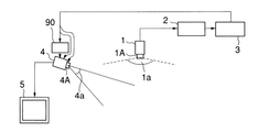
次に、図5に第二の従来における監視システムのブロック図を示す。1は画像入力用カメラ、2は画像処理装置、3はカメラ制御装置、1Aは画像入力用カメラ1の広角レンズ、1aは画像入力用カメラ1の撮像範囲、を示す。画像入力用カメラ1には広角レンズ1Aを組合せて、監視エリアの上部から撮像することにより、監視エリアの全範囲を死角なしに捕らえる。画像入力用カメラ1で撮像された監視エリア内の監視画像は、画像処理装置2に入力され画像処理することにより監視エリア内の侵入物体の検知を行う画像を得る。侵入物体が検知された場合には、画像処理装置2から監視エリア内の侵入物体の位置および大きさなどの侵入物体情報をカメラ制御装置3に出力される。カメラ制御装置3は、この侵入物体情報を元に監視用カメラ4の旋回ユニット90および監視用カメラ4のズームレンズ4Aを制御することで、侵入物体を最適に撮像するカメラ制御情報を生成する。
【0008】
【発明が解決しようとする課題】
本発明は、カメラなどの撮像装置で撮像して得た監視画像を画像処理し、侵入物体を検知して追尾する監視システムにおいて、画像入力用カメラおよび画像処理装置の設置台数を減らすことで、カメラ調整および画像処理装置の設置作業の時間を短縮するとともに、画像入力用カメラおよび監視カメラを同一のカメラケースに収納して設置場所をとらない監視カメラシステムを提供することにある。
【0009】
【課題を解決するための手段】
本発明は、上記の課題を達成するため、広い撮像範囲を確保できる広角レンズを具備して、侵入物体の侵入検知のための侵入検知画像をとらえる画像入力用カメラと、前記広角レンズの光軸延長線の周囲を旋回して水平方向の撮像範囲を確保すると共に垂直方向に回転して上下方向の撮像範囲を確保することで任意方向の撮像範囲に設定されて前記侵入物体の追尾画像をとらえる監視用カメラと、前記監視用カメラの旋回による水平方向と垂直方向の回転による上下方向から任意の撮像範囲の設定を担う旋回部と、前記画像入力用カメラからの画像を元に画像処理して侵入物体を検知して、前記侵入物体の位置、大きさ、あるいは輝度などの侵入物体情報を生成し出力する画像処理部と、前記侵入物体情報を受けて、前記監視用カメラを前記侵入物体の撮像範囲に向ける前記旋回部への位置制御情報、さらに前記監視用カメラの制御を行うカメラ制御情報を生成して出力するカメラ制御部と、から成る監視カメラ装置としたもので、前記監視カメラ装置から出力される侵入物体の追尾画像をモニタに表示することで侵入物体の監視を行うようにしたものである。
【0010】
【発明の実施の形態】
本発明の一実施例を図1に示す。
【0011】
本発明の監視カメラ装置100の追尾画像信号15は、モニタ5に表示される。監視カメラ装置100の構成は次のようになっている。6は監視画像を得る画像入力用カメラ、6Aは監視範囲を撮像範囲6aとして結像する画像入力用カメラ6の広角レンズ、10は侵入物体の追尾画像をとらえる監視用カメラ、10Aは追尾範囲を撮像範囲10aとして結像する監視用カメラ10のズームレンズ、9は監視用カメラ10の旋回による水平方向の撮像範囲と垂直方向の回転による上下方向の撮像範囲を得て任意の撮像範囲の設定を担う旋回部、7は画像入力用カメラ6で得られた監視画像を元に画像処理して侵入物体20を検知して、侵入物体の位置、大きさなどの侵入物体情報を生成して出力する画像処理部、8は侵入物体情報を受けて、監視用カメラ10を侵入物体の撮像範囲に向ける旋回部9への位置制御情報8a、さらに監視用カメラ10の制御を行うカメラ制御情報8bを生成して出力するカメラ制御部、である。また、ズームレンズ10A、監視用カメラ10および旋回部9は、同時に広角レンズ6Aの光軸を中心に180度回転した後には点線で示されている位置に移る。そして、14は以上の構成要素を納めるためのドーム形ケースである。
【0012】
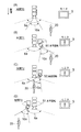
この動作を図3で説明する。
図3では説明をわかりやすくするため、各部間の情報を伝達する信号線などを省略した図としている。また、同図(A)においては、監視用カメラ10、旋回部9、およびズームレンズ10Aは、画像入力用カメラの後方の位置に移っていることを示している。
【0013】
まず、最初に侵入物体20が時間T0に撮像範囲6a内に侵入したとする。ただし、この時は、まだ監視用カメラ10の撮像範囲10a内には侵入していない。
【0014】
しかし、画像入力用カメラ6で侵入物体20は撮像されており、その監視画像を元に画像処理部7で画像処理されて侵入物体20の侵入検知が行われる。そして、検知された侵入物体20の位置や大きさあるいは輝度などの侵入物体情報が生成されて、カメラ制御部8へ出力される。
【0015】
カメラ制御部8は、この侵入物体情報を元に監視用カメラ10の撮像範囲10aを侵入物体20の方向に設定するための位置制御情報8aと侵入物体20を最適に撮像するために大きさや輝度などの情報を元に監視用カメラ10のカメラ制御情報8bを生成する。位置制御情報8aは旋回部9へ、カメラ制御情報8bは監視用カメラ10へ供給される。すると、時間T1には、位置制御情報8aによって旋回部9は監視用カメラ10と共に水平回転51により図3(B)に移り、撮像範囲10aを侵入物体20の方向に設定される。この結果、モニタ5には侵入物体20の追尾画像が映し出される。
【0016】
さらに、図3(C)のように、時間T2で侵入物体20が図面の左方向に移って画像入力用カメラ6の真下近辺にいるようになっても、画像入力用カメラ6の広角レンズ6aで侵入物体20の監視画像は得られる。そして、この監視画像を元に前述のように画像処理部6で侵入物体20の検知が継続されて、侵入物体情報が生成されて、随時カメラ制御部8から位置制御情報8aとカメラ制御情報8bが各々旋回部9と監視用カメラ10へ出力される。これに伴って、図3(C)のように、監視用カメラ10の撮像範囲10aの方向が垂直方向の回転52による上下方向の撮像範囲のみを変えられて、時間T1から時間T2までに移動している侵入物体20を追尾するように設定される。これにより、モニタ5には画像入力用カメラ6の真下近辺にいる侵入物体20の追尾画像を表示することができる。
【0017】
そして、図3(D)の時間T3では、画像入力用カメラ6の監視画像を元に生成された侵入物体情報に基づいて監視用カメラ10、旋回部9およびズームレンズ10aと共に水平回転51により、画像入力用カメラ6の光軸を中心に旋回されて、侵入物体20が図面の左に位置したとしても、その方向に監視用カメラ10の撮像範囲10aが設定されるので、侵入物体20の追尾画像がモニタ5に映し出され続けられる。
【0018】
また、監視カメラ装置100から画像処理部7、カメラ制御部8を外部に設置した、第二の実施例の監視カメラ装置101を図2に示す。このような構成とすることで、装置を小型化にできるようになる。その動作は、上記と同様であるため省略する。
【0019】
【発明の効果】
本発明によれば、画像入力用カメラおよび画像処理装置の設置台数を減らすことができてカメラ調整および画像処理装置の設置作業の時間を短縮することができると共にシステム導入費やメンテナンス費の削減が図れ、さらには画像入力用カメラおよび監視用カメラを同一のカメラケースに収納して設置場所をとらない監視カメラ装置を提供することができる。
【図面の簡単な説明】
【図1】 本発明の第一の実施例における監視カメラ装置の構成図
【図2】 本発明の第二の実施例における監視カメラ装置の構成図
【図3】 本発明の第一および第二の実施例における監視カメラ装置の動作を説明するための図
【図4】 従来の監視カメラ装置の構成を示す第一の例を示す図
【図5】 従来の監視カメラ装置の構成を示す第二の例を示す図
【符号の説明】
1、11〜13:画像入力用カメラ、1A:広角レンズ、2、21〜23:画像処理装置、3:カメラ制御装置、4:監視用カメラ、4A:ズームレンズ、5:モニタ、6a、10a、11a、11b、1c:撮像範囲、6:画像入力用カメラユニット、7:画像処理部、8:カメラ制御部、8a位置制御情報、8b:カメラ制御情報、9:旋回部、9、90:旋回ユニット、10:監視用カメラ、10A:ズームレンズ、15:追尾画像信号、20:侵入物体、51:水平回転、52:垂直回転、100、101:監視カメラ装置[0001]
BACKGROUND OF THE INVENTION
The present invention relates to a monitoring camera device in a monitoring system that performs image processing on an image obtained by an imaging device such as a television camera, detects an intruding object, and tracks the object.
[0002]
[Prior art]
An example of a conventional monitoring system is shown in FIG. A plurality of image input cameras are installed in order to secure a wide monitoring area and to prevent a blind spot for monitoring in the monitoring area.
[0003]
In FIG. 4,
[0004]
The conventional monitoring system captures the monitoring area with a plurality of
[0005]
In order to secure a wide monitoring area and to prevent a monitoring blind spot in the monitoring area, it is necessary to install a plurality of image input cameras. In addition, an image processing apparatus must be installed for each of the
[0006]
If a plurality of image input cameras and image processing apparatuses are installed, system introduction costs and maintenance costs increase, and it takes time to adjust and set the equipment.
[0007]
Next, FIG. 5 shows a block diagram of a second conventional monitoring system.
[0008]
[Problems to be solved by the invention]
The present invention image-processes a monitoring image obtained by imaging with an imaging device such as a camera, and in a monitoring system that detects and tracks an intruding object, by reducing the number of installed image input cameras and image processing devices, An object of the present invention is to provide a surveillance camera system that shortens the time required for camera adjustment and installation of an image processing apparatus, and that accommodates an image input camera and a surveillance camera in the same camera case and does not take up an installation location.
[0009]
[Means for Solving the Problems]
In order to achieve the above object, the present invention includes an image input camera that includes a wide-angle lens capable of securing a wide imaging range and captures an intrusion detection image for intrusion detection of an intruding object, and an optical axis of the wide-angle lens. Rotate around the extension line to secure a horizontal imaging range and rotate vertically to secure an imaging range in the vertical direction to capture the tracking image of the intruding object set to an arbitrary imaging range Image processing is performed based on images from the monitoring camera, a swivel unit that is responsible for setting an arbitrary imaging range from the vertical direction by horizontal and vertical rotation of the monitoring camera, and the image input camera. An image processing unit that detects an intruding object, generates and outputs intruding object information such as the position, size, or luminance of the intruding object; receives the intruding object information; Positioning control information to the swivel unit directed to the imaging range of the incoming object, and further a camera control unit for generating and outputting camera control information for controlling the monitoring camera, a monitoring camera device, The intruding object is monitored by displaying a tracking image of the intruding object output from the monitoring camera device on the monitor.
[0010]
DETAILED DESCRIPTION OF THE INVENTION
An embodiment of the present invention is shown in FIG.
[0011]
The
[0012]
This operation will be described with reference to FIG.
In FIG. 3, in order to make the description easy to understand, a signal line for transmitting information between each part is omitted. Further, FIG. 4A shows that the
[0013]
First, it is assumed that the
[0014]
However, the
[0015]
The
[0016]
Further, as shown in FIG. 3C, even when the intruding
[0017]
At time T3 in FIG. 3D, the horizontal rotation 51 is performed together with the monitoring
[0018]
FIG. 2 shows a
[0019]
【The invention's effect】
According to the present invention, the number of installed image input cameras and image processing apparatuses can be reduced, the time required for camera adjustment and installation of the image processing apparatus can be shortened, and system introduction costs and maintenance costs can be reduced. In addition, it is possible to provide a monitoring camera device that does not take an installation place by storing the image input camera and the monitoring camera in the same camera case.
[Brief description of the drawings]
FIG. 1 is a block diagram of a surveillance camera device in a first embodiment of the present invention. FIG. 2 is a block diagram of a surveillance camera device in a second embodiment of the present invention. FIG. 4 is a diagram for explaining the operation of the surveillance camera device in the embodiment of the present invention. FIG. 4 is a diagram showing a first example of the configuration of the conventional surveillance camera device. FIG. Diagram showing an example
DESCRIPTION OF
Claims (3)
広角レンズを有して前記監視エリアを撮像して監視画像を得る画像入力用カメラと、前記広角レンズの光軸延長線を中心に前記物体情報に基づいて旋回しあるいは垂直回転し、前記物体を追尾する監視用カメラと、前記監視用カメラの旋回あるいは垂直回転の動きを制御する旋回部と、を備えることを特徴とする監視カメラ装置Imaging a monitoring area of the object to obtain a monitoring image, a monitoring camera apparatus for obtaining the image by tracking the object based on object information obtained by detecting the object from the monitoring image,
An image input camera that has a wide-angle lens and captures the monitoring area to obtain a monitoring image, and rotates or vertically rotates based on the object information about the optical axis extension line of the wide-angle lens, a monitoring camera to be tracked, the a turning unit for controlling the movement of the pivoting or vertical rotation of the monitor camera, monitoring camera apparatus, characterized in that it comprises a
前記画像入力用カメラ、前記監視用カメラ、および前記旋回部とを同一の収納体に納めたことを特徴とする監視カメラ装置。In the invention of claim 1,
A surveillance camera device, wherein the image input camera, the surveillance camera, and the swivel unit are housed in the same housing.
前記監視画像から前記物体情報を生成する画像処理部と、前記物体情報に基づいて前記監視用カメラを制御するカメラ制御情報および前記旋回部を制御する位置制御情報を生成するカメラ制御部と、を有することを特徴とする監視カメラ装置。In the invention of claim 2,
An image processing unit that generates the object information from the monitoring image, a camera control unit that controls the monitoring camera based on the object information, and a camera control unit that generates position control information for controlling the turning unit. A surveillance camera device comprising:
Priority Applications (1)
| Application Number | Priority Date | Filing Date | Title |
|---|---|---|---|
| JP2001045275A JP3838881B2 (en) | 2001-02-21 | 2001-02-21 | Surveillance camera device |
Applications Claiming Priority (1)
| Application Number | Priority Date | Filing Date | Title |
|---|---|---|---|
| JP2001045275A JP3838881B2 (en) | 2001-02-21 | 2001-02-21 | Surveillance camera device |
Publications (3)
| Publication Number | Publication Date |
|---|---|
| JP2002247424A JP2002247424A (en) | 2002-08-30 |
| JP2002247424A5 JP2002247424A5 (en) | 2005-11-10 |
| JP3838881B2 true JP3838881B2 (en) | 2006-10-25 |
Family
ID=18907104
Family Applications (1)
| Application Number | Title | Priority Date | Filing Date |
|---|---|---|---|
| JP2001045275A Expired - Fee Related JP3838881B2 (en) | 2001-02-21 | 2001-02-21 | Surveillance camera device |
Country Status (1)
| Country | Link |
|---|---|
| JP (1) | JP3838881B2 (en) |
Families Citing this family (5)
| Publication number | Priority date | Publication date | Assignee | Title |
|---|---|---|---|---|
| JP4792300B2 (en) * | 2005-08-12 | 2011-10-12 | イーストマン コダック カンパニー | Imaging apparatus having a plurality of optical systems |
| JP4589261B2 (en) | 2006-03-31 | 2010-12-01 | パナソニック株式会社 | Surveillance camera device |
| EP2607951B1 (en) | 2011-12-19 | 2013-12-11 | Axis AB | Method for setting up a monitoring camera |
| JP2014135683A (en) * | 2013-01-11 | 2014-07-24 | Sumitomo Electric Ind Ltd | Imaging control apparatus, imaging control method, and imaging control program |
| JP7197981B2 (en) * | 2018-01-24 | 2022-12-28 | キヤノン株式会社 | Camera, terminal device, camera control method, terminal device control method, and program |
-
2001
- 2001-02-21 JP JP2001045275A patent/JP3838881B2/en not_active Expired - Fee Related
Also Published As
| Publication number | Publication date |
|---|---|
| JP2002247424A (en) | 2002-08-30 |
Similar Documents
| Publication | Publication Date | Title |
|---|---|---|
| US10861304B2 (en) | Monitoring camera and monitoring camera control method | |
| JP4566166B2 (en) | Imaging device | |
| US9041800B2 (en) | Confined motion detection for pan-tilt cameras employing motion detection and autonomous motion tracking | |
| KR101187908B1 (en) | Integrated surveillance system diplaying a plural of event images and method using the same | |
| US20060139484A1 (en) | Method for controlling privacy mask display | |
| KR20100129125A (en) | Intelligent panorama camera, circuit and method for controlling thereof, and video monitoring system | |
| WO2009066988A2 (en) | Device and method for a surveillance system | |
| KR20110044101A (en) | Watching apparatus using dual camera | |
| EP2926545A1 (en) | Imaging system and process | |
| WO2007021143A1 (en) | Pan/tilt camera apparatus having auxiliary camera | |
| JP3838881B2 (en) | Surveillance camera device | |
| JP4535919B2 (en) | Surveillance system, surveillance camera, and controller | |
| JP2001245284A (en) | Method and system for supervising intruding object | |
| JP2009044475A (en) | Monitor camera system | |
| JPH02239779A (en) | Automatic focusing, automatic picture angle adjustment, automatic visual line aligner and television doorphone set having them | |
| KR101061868B1 (en) | Monitoring system using dual surveillance camera | |
| JP2006115080A (en) | Monitor camera controller and monitor camera system | |
| KR100872403B1 (en) | Monitor system controlling ptz camera by using fixed camera | |
| JPH11275566A (en) | Monitoring camera apparatus | |
| JP2009157446A (en) | Monitoring system | |
| JP4407530B2 (en) | Motion detection device | |
| KR100278989B1 (en) | Closed Circuit Monitoring Apparatus and Method | |
| KR101255143B1 (en) | On-vehicles type camera system comprising monitoring function and monitoring method thereof | |
| KR20070038656A (en) | Method for controlling cooperation monitoring in digital video recorder | |
| JP2005260778A (en) | Monitoring camera |
Legal Events
| Date | Code | Title | Description |
|---|---|---|---|
| A521 | Request for written amendment filed |
Free format text: JAPANESE INTERMEDIATE CODE: A523 Effective date: 20050916 |
|
| A621 | Written request for application examination |
Free format text: JAPANESE INTERMEDIATE CODE: A621 Effective date: 20050916 |
|
| A977 | Report on retrieval |
Free format text: JAPANESE INTERMEDIATE CODE: A971007 Effective date: 20060726 |
|
| TRDD | Decision of grant or rejection written | ||
| A01 | Written decision to grant a patent or to grant a registration (utility model) |
Free format text: JAPANESE INTERMEDIATE CODE: A01 Effective date: 20060801 |
|
| A61 | First payment of annual fees (during grant procedure) |
Free format text: JAPANESE INTERMEDIATE CODE: A61 Effective date: 20060801 |
|
| R150 | Certificate of patent or registration of utility model |
Free format text: JAPANESE INTERMEDIATE CODE: R150 Ref document number: 3838881 Country of ref document: JP Free format text: JAPANESE INTERMEDIATE CODE: R150 |
|
| FPAY | Renewal fee payment (event date is renewal date of database) |
Free format text: PAYMENT UNTIL: 20100811 Year of fee payment: 4 |
|
| FPAY | Renewal fee payment (event date is renewal date of database) |
Free format text: PAYMENT UNTIL: 20110811 Year of fee payment: 5 |
|
| FPAY | Renewal fee payment (event date is renewal date of database) |
Free format text: PAYMENT UNTIL: 20120811 Year of fee payment: 6 |
|
| FPAY | Renewal fee payment (event date is renewal date of database) |
Free format text: PAYMENT UNTIL: 20130811 Year of fee payment: 7 |
|
| FPAY | Renewal fee payment (event date is renewal date of database) |
Free format text: PAYMENT UNTIL: 20140811 Year of fee payment: 8 |
|
| R250 | Receipt of annual fees |
Free format text: JAPANESE INTERMEDIATE CODE: R250 |
|
| LAPS | Cancellation because of no payment of annual fees |