JP3836070B2 - Gas ejection device for airbag expansion test - Google Patents
Gas ejection device for airbag expansion test Download PDFInfo
- Publication number
- JP3836070B2 JP3836070B2 JP2002322074A JP2002322074A JP3836070B2 JP 3836070 B2 JP3836070 B2 JP 3836070B2 JP 2002322074 A JP2002322074 A JP 2002322074A JP 2002322074 A JP2002322074 A JP 2002322074A JP 3836070 B2 JP3836070 B2 JP 3836070B2
- Authority
- JP
- Japan
- Prior art keywords
- gas
- airbag
- pressure
- gas ejection
- expansion test
- Prior art date
- Legal status (The legal status is an assumption and is not a legal conclusion. Google has not performed a legal analysis and makes no representation as to the accuracy of the status listed.)
- Expired - Fee Related
Links
- 238000012360 testing method Methods 0.000 title claims description 59
- 239000007789 gas Substances 0.000 description 162
- 238000009825 accumulation Methods 0.000 description 17
- 239000010720 hydraulic oil Substances 0.000 description 12
- 239000012530 fluid Substances 0.000 description 8
- 230000007423 decrease Effects 0.000 description 7
- 238000000034 method Methods 0.000 description 7
- 238000002347 injection Methods 0.000 description 5
- 239000007924 injection Substances 0.000 description 5
- IJGRMHOSHXDMSA-UHFFFAOYSA-N Atomic nitrogen Chemical compound N#N IJGRMHOSHXDMSA-UHFFFAOYSA-N 0.000 description 3
- 239000003795 chemical substances by application Substances 0.000 description 3
- 229910001873 dinitrogen Inorganic materials 0.000 description 3
- 238000006073 displacement reaction Methods 0.000 description 3
- 239000003921 oil Substances 0.000 description 3
- 208000034656 Contusions Diseases 0.000 description 2
- 238000006243 chemical reaction Methods 0.000 description 2
- 238000004891 communication Methods 0.000 description 2
- 230000000694 effects Effects 0.000 description 2
- 238000002474 experimental method Methods 0.000 description 2
- 239000011261 inert gas Substances 0.000 description 2
- 230000002123 temporal effect Effects 0.000 description 2
- 238000010998 test method Methods 0.000 description 2
- 238000001514 detection method Methods 0.000 description 1
- 238000010586 diagram Methods 0.000 description 1
Images


Landscapes
- Air Bags (AREA)
Description
【0001】
【発明の属する技術分野】
本発明は、エアバッグ膨張試験用ガス噴出装置に関する。
【0002】
【従来の技術】
近年、自動車の衝突事故発生時に乗員を保護するため、シートベルトと共にエアバッグが採用されている。前記エアバッグは、自動車の衝突時に瞬時に膨らみ、乗員がハンドルや計器類に直接衝突することを防ぎ、頭部や胸部への衝撃を軽減するものである。しかし、前記エアバッグの膨張速度は時速100km〜300kmに達するため、エアバッグが膨らむときに、乗員が擦過傷、打撲傷、骨折等の被害を受けるおそれがある。よって、エアバッグの製品化の際には、乗員がハンドルや計器類に直接衝突することを防ぐとともに、乗員が擦過傷、打撲傷、骨折等の被害を受けないことが要求されている。そのため、エアバッグ膨張試験を多数回行い、乗員に対する影響を調べる必要がある。
【0003】
エアバッグを膨張させる手段として、インフレータと呼ばれるガス発生装置が用られ、インフレータがエアバッグ内部にガスを発生させる。このインフレータには、化学反応によるガス発生方式がある。化学反応によるガス発生方式のインフレータは、ガス発生剤を用い、エアバッグ展開信号により点火装置が点火剤に点火し、点火剤が発熱し、この熱によりガス発生剤で熱反応が起こり、ガスが発生する構造となっている。したがって、このようなインフレータは一度使うと、再度使うことができない。そのため、繰り返し試験を行うエアバッグの試験では非経済的である。そこで、エアバッグの試験では、インフレータを用いる代わりに、高圧ガスタンクによるガス噴出装置を用いる。高圧ガスタンクによるガス噴出装置では、窒素ガスなどの不活性ガスが加圧充填している容器を用い、エアバッグ展開信号により、噴出口からエアバッグ内部へと不活性ガスが噴出する構造となっている。よって、高圧ガスタンクによるガス噴出装置は、タンクにガスを封入すれば何度も使える構造となっているので、経済的である。
【0004】
ここで、エアバッグの膨張試験に用いられる従来のエアバッグ膨張試験用ガス噴出装置の一例を図5に示す。
図5に示すように、エアバッグ膨張試験用ガス噴出装置は、圧力容器101の中心軸上の一端部にガス噴射口102を形成するとともに、他端部にガス噴射口102より大きい径のシリンダ103を形成し、ガス噴射口102を開閉する弁体104とシリンダ103内のピストン105をロッド106で連結するようにしてあり、圧力容器101にガス送給孔107から試験用のガスを充填し、シリンダ103に供給したガスで弁体104を閉じたり、シリンダ103からガスを排気して弁体104を開いてガスをエアバッグ108に噴出するようになっている(例えば、特許文献1参照)。
【0005】
さらに、エアバッグの膨張試験に用いられる従来のエアバッグ膨張試験用ガス噴出装置の他の一例を図6に示す。
図6に示すように、エアバッグ膨張試験用ガス噴出装置は、試験用流体が充填される蓄圧シリンダ111と連通路(ガス流路)112を介して連通する制御用シリンダ113を設け、この一端に流体噴射口114を形成し、制御用シリンダ113内に装着したトリガーピストン115で連通路(ガス流路)112の開閉を制御して蓄圧シリンダ111内の高圧の流動流体を流体噴射口114から模擬インフレータ116を介してエアバッグ110に噴出する。
この試験装置では、トリガーピストン115を試験用流体とは別の低圧の作動流体で制御できる(例えば、特許文献2参照)。
【0006】
【特許文献1】
特開平1−269639号公報
【特許文献2】
特開平7−83800号公報
【0007】
【発明が解決しようとする課題】
しかしながら、図5に示すような従来のエアバッグ膨張試験用ガス噴出装置は、エアバッグ108が膨らむまでの時間などの噴射特性を変えようとすると、弁体104とピストン105の大きさを変えなければならず、簡単に対応できないという問題がある。
また、図6に示すような従来のエアバッグ膨張試験用ガス噴出装置は、エアバッグが膨らむまでの時間などの噴出特性を変えることができるものの、1試験中にガス噴出特性を調整することができないという問題がある。
さらに、図5や図6に示すような従来のエアバッグ膨張試験用ガス噴出装置は、自動車に装備されたエアバッグと接続できないので、エアバッグの使用環境と同一条件で、エアバッグ膨張試験ができないという問題がある。
【0008】
このようなことから、本発明は、ガス噴出特性が調整可能なエアバッグ膨張試験用ガス噴出装置を提供することを目的としてなされたものである。
【0009】
【課題を解決するための手段】
前述した課題を解決する第1の発明に係るエアバッグ膨張試験用ガス噴出装置の構成は、エアバッグが接続されるガス供給通路と、前記ガス供給通路に高圧ガスを供給するガス供給手段と、前記ガス供給通路における前記エアバッグが接続される部分と前記ガス供給手段との間に設けられ、前記ガス供給通路を開閉する流量制御弁と、前記流量制御弁の開閉を制御する制御手段と、を備え、上記高圧ガスの温度および圧力に応じて、上記制御手段による前記流量制御弁の開閉の制御を調整するようにしたことを特徴とする。
前記ガス供給手段としては、例えば蓄圧タンクとこの蓄圧タンクにガスを高圧充填するガスチャージャとからなるものが挙げられる。また、前記制御手段としては、例えば計算機とこの計算機からの制御情報により開閉制御されるサーボ弁からなるものが挙げられる。
この発明に係るエアバッグ膨張試験用ガス噴出装置によれば、ガス供給通路に流量制御弁があり、この流量制御弁の開閉を制御装置で制御するので、エアバッグへのガス噴出量の調整ができる。
【0012】
第2の発明は、第1の発明に係るエアバッグ膨張試験用ガス噴出装置において、前記ガス供給通路を自動車に装備されたエアバッグに接続して、前記エアバッグの膨張試験を行うことを特徴とする。
この発明に係るエアバッグ膨張試験用ガス噴出装置を用いれば、ガス供給通路を自動車に装備されたエアバッグに直接接続できる。
【0013】
第3の発明は、第1の発明に係るエアバッグ膨張試験用ガス噴出装置において、可搬式としたことを特徴とする。
可搬式とする手段としては、装置をラックに搭載することなどが考えられる。この装置では、試験を行う自動車の側に搬送できるので、エアバッグ膨張試験の効率化が図れる。
【0014】
【発明の実施の形態】
本発明によるエアバッグ膨張試験用ガス噴出装置の実施の形態を以下に説明するが、本発明はこれらの実施の形態に限定されるものではない。
【0015】
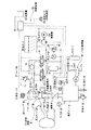
図1は本発明の一実施形態であるエアバッグ膨張試験用ガス噴出装置の概略図である。
図1に示すように、このエアバッグ膨張試験用ガス噴出装置は、エアバッグ1が接続されるガス供給通路51と、前記ガス供給通路51に高圧ガスを供給するガス供給装置52と、前記ガス供給通路51における前記エアバッグ1が接続される部分と前記ガス供給装置52との間に設けられ、前記ガス供給通路51を開閉する流量制御弁11と、前記流量制御弁11の開閉を制御する制御装置53と、を備える。
ここで、ガス供給通路51は、ガス流路2と高圧ホース32からなる。また、ガス供給装置51は、ガスチャージャ5と蓄圧タンク6などからなる。さらに、制御装置53は、計算機20とサーボ弁17と油圧シリンダ14などからなる。ガス流路2の一端には、遮断弁3を介してガス供給装置52の蓄圧タンク6が接続される。遮断弁3を閉じることで、ガス流路2と蓄圧タンク6との系が閉じる。ガス流路2の他端には、高圧ホース32が取り付けられ、高圧ホース32の先端がエアバッグ1に接続される。
【0016】
ここで、ガス供給通路51に高圧ガスを供給するガス供給装置52は、ボンベ(例えば、N2 ガスボンベ)4が止め弁7とガスチャージャ5を介して蓄圧タンク6に接続される。ボンベ4からガスチャージャ5を介して、蓄圧タンク6内に高圧ガスを充填する。ガスチャージャ5を使うことで、ボンベ4内に封入されるガスを使い切ることができると共に、蓄圧タンク6内にあるガスを高圧状態に保つことができる。また、ボンベ4とガスチャージャ5との間に止め弁7が設けられ、この止め弁7を閉じることで、ボンベ4と蓄圧タンク6との間の系が閉じ、ボンベ4の交換が容易となる。
また、蓄圧タンク6には、圧力計8および安全弁9および逃がし弁10が設けられる。この逃がし弁10を操作することにより、蓄圧タンク6内の圧力を下げることができる。
【0017】
ガス供給通路51を構成するガス流路2に設けられ、このガス流路2を開閉する流量制御弁11は、弁体12と弁座13とで形成される。弁体12は、ロッド16を介して、油圧シリンダ14内のピストン15と連結する。
油圧シリンダ14内のピストン15が駆動すると、ロッド16を介して連結する弁体12が駆動し、流量制御弁11が開閉する。油圧シリンダ14内のピストン15は、サーボ弁17による油圧の給排により駆動され、サーボ弁17はサーボアンプ18、インターフェイス19を介して、計算機(CPU)20により制御される。また、サーボ弁17は、アキュムレータ21、油圧ポンプ22と連結する。なお、図1では、油圧シリンダ14にサーボ弁17が並列にて連結することにより、ピストン15の駆動速度を上げている。
【0018】
油タンク23から供給される作動油を使用し、この油圧タンク23から油圧ポンプ22を介して接続するアキュムレータ21にて、油圧が蓄圧される。この油圧ポンプ22は、電動機24により駆動される。
また、サーボ弁17へ油圧がかかりすぎないように、アキュムレータ21と油圧ポンプ22との間に圧力計25とリリーフ弁26が設けられ、油圧シリンダ14へ油圧がかかりすぎないように、油圧シリンダ14とサーボ弁17との間にリリーフ弁27が設けられる。
【0019】
ここで、流量制御弁11の開閉を制御する制御装置53は、蓄圧タンク6内に充填されるガス状態を検出する機能とともに検出した情報および計算機20にあるプログラムに応じて、流量制御弁11を制御する機能を備える。
【0020】
蓄圧タンク6内に充填されるガス状態の検出は、蓄圧タンク6に設けられる温度センサ28および圧力センサ29によりなされる。この温度センサ28およびこの圧力センサ29が検出した蓄圧タンク6内に充填されるガス状態に関する情報は、インターフェイス19を介して、計算機20に送られる。また、ガス体積量は、一定圧力下では、温度に依存するので、蓄積タンク6から流出するガス体積量とエアバッグ1内へ噴出するガス体積量とが異なることがある。エアバッグ1へ適切なガス体積量を噴出するため、温度センサ30により実験を行う自動車内の温度を検出する。検出した自動車内の温度情報は、インターフェイス19を介して計算機20に送られる。
【0021】
また、検出した情報および計算機20にあるプログラムに応じた、流量制御弁11の制御は、上記蓄圧タンク6内のガス状態情報および上記自動車内の温度情報に応じ、入力されたガス噴出特性を補正し、計算機20にあるプログラムで計算機20が流量制御弁11の制御情報を計算し、計算機20がインターフェイス19とサーボアンプ18を介してサーボ弁17に制御情報を送り、サーボ弁17を開閉することにより、サーボ弁17から油圧シリンダ14への作動油流量を制御し、ピストン15を駆動することによりなされる。つまり、計算機20は、流量制御弁11の開閉を制御するので、ガス噴出特性を調整できる。
【0022】
また、変位センサ31が油圧シリンダ14に設けられ、油圧シリンダ14の変位情報を検出する。この変位情報は、インターフェイス19を介して、計算機20へ送られ、サーボ弁17を制御する精度を上げるために用いられることができる。
上記エアバッグ膨張試験用ガス噴出装置は、ラックなどの台車に搭載され、試験を行う自動車の側に搬送されるようになっている。なお、エアバッグ膨張試験用ガス噴出装置は、工場内の設備として設け、この装置の近くに試験すべき自動車を搬入するようにしてもよい。
【0023】
次に、本発明の一実施形態である図1に示したエアバッグ膨張試験用ガス噴出装置を用いた試験手順について説明する。
最初に、止め弁7および遮断弁3を閉じるとともに、高圧ホース32を介して、本エアバッグ膨張試験用ガス噴出装置と、自動車に装備されたエアバッグ1とを接続する。また、例えば乗員への影響を検証する際には、自動車の運転席にダミー人形を搭載する。止め弁7とガスチャージャ5を介して蓄圧タンク6にボンベ4を接続し、止め弁7を開く。ガスチャージャ5により蓄圧タンク6に窒素ガスが充填される。ここで、流量制御弁11が閉じていることを確認し、遮断弁3を開く。窒素ガスが流量制御弁11まで、充満した状態となる。
【0024】
計算機20は、蓄圧タンク6に設けられた温度センサ28および圧力センサ29から蓄圧タンク6内のガス状態情報と、温度センサ30から自動車内の温度情報とを収集する。上記蓄圧タンク6内のガス状態情報および上記自動車内の温度情報に応じて、計算機20は、入力したガス噴出特性から、流量制御弁11の制御情報を計算する。この計算機20がインターフェイス19とサーボアンプ18を介して、サーボ弁17に制御情報を送る。アキュムレータ21が油タンク23から油圧ポンプ22を介して流入する作動油に油圧をかけるとともに蓄圧し、電動機24により駆動される油圧ポンプ22が作動油に油圧をかける。ここで、サーボ弁17が開閉すると、作動油は、サーボ弁17を介して油圧シリンダ14内へ流入し、ピストン15を駆動する。このピストン15が駆動すると、ロッド16を介して連結する弁体12が駆動し、流量制御弁11が開閉する。この流量制御弁11が開閉することにより、エアバッグ1へのガス噴出量が制御される。
【0025】
ガスが抜けるための穴あきエアバッグなどのエアバッグの種類やエアバッグのたたみ方により、エアバッグの膨らみ方が変わり、エアバッグ内の圧力が安定しないため、ガス噴出特性が一特性とならない。そのため、エアバッグ膨張試験の際、試験したいガス噴出特性を特定するために、エアバッグの代わりに、定容積タンクが使われる。
ここで、例として定容積タンクへのガス噴出における圧力の時間的特性を図2に示す。実線は1段式を示し、点線は2段式を示す。1段式とは、ガスを1回噴出することによりエアバッグを膨張させる方法であり、2段式とは、ガスを2回噴出することによりエアバッグを膨張させる方法である。1段式のガス噴出特性では、圧力が短時間で一定値となり、2段式のガス噴出特性では、圧力がある値まで増加して一定となり、さらに増加して一定となる。
【0026】
定容積タンクへのガス噴出をガス流量の時間的特性で示すと図3のようになる。ここで、実線は1段式を示し、点線は2段式を示す。
1段式のガス噴出特性では、ガス流量が、短時間で急激に増加して最大ガス流量となり、ガス流量が増加する時間より長い時間で緩やかに減少している。また、2段式のガス噴出特性では、ガス流量が、短時間に増加して、最大ガス流量となり、短時間で減少して0となる。再び、短時間で増加して、最大ガス流量となり、短時間で減少して0となる。
【0027】
さらに、エアバッグ膨張試験用ガス噴出装置のサーボ弁における作動油流量の時間的変化を図4に示す。ここで、実線は1段式を示し、点線は2段式を示す。
1段式のガス噴出特性では、作動油流量がプラス側で短時間に増加減少して0となり、マイナス側で緩やかな増加減少の曲線を描き0となる。また、2段式のガス噴出特性では、作動油流量がプラス側で増加減少の2次曲線およびマイナス側で増加減少の2次曲線を描き、プラス側の曲線およびマイナス側の曲線が2つ連続する。
【0028】
計算機20に図2に示すようなガス噴出特性を入力すると、計算機20が図4に示すようなサーボ弁17での作動油流量の情報を算出し、サーボ弁17の開閉を制御することで、流量制御弁13の開閉を制御し、図3に示すようなガス噴出特性となるようにエアバッグ1へのガス噴出量が制御される。
【0029】
つまり、図2の実線で示すような1段式のガス噴出特性を計算機20に入力すると、蓄圧タンク6内のガス状態に応じて、計算機20が図4に示すようなサーボ弁17での作動油流量の情報を計算して、サーボ弁17の開閉を制御し、サーボ弁17から油圧シリンダ14へ作動油を給排し、油圧シリンダ14内のピストン15を駆動し、ピストン15がロッド16を介して連結する弁体を駆動し、流量制御弁11の開閉を制御し、図3の実線で示す1段式のガス噴出特性となるようにエアバッグ1へのガス噴出量が制御される。
【0030】
図2の点線で示すような2段式のガス噴出特性を計算機20に入力すると、蓄圧タンク6内のガス状態に応じて、計算機20が図4に示すようなサーボ弁17での作動油流量の情報を計算して、サーボ弁17の開閉を制御し、サーボ弁17から油圧シリンダ14へ作動油を給排し、油圧シリンダ14内のピストン15を駆動し、ピストン15がロッド16を介して連結する弁体を駆動し、流量制御弁11の開閉を制御し、図3の点線で示す2段式のガス噴出特性となるようにエアバッグ1へのガス噴出量が制御される。
【0031】
【発明の効果】
第1の発明に係るエアバッグ膨張試験用ガス噴出装置によれば、エアバッグが接続されるガス供給通路と、前記ガス供給通路に高圧ガスを供給するガス供給手段と、前記ガス供給通路における前記エアバッグが接続される部分と前記ガス供給手段との間に設けられ、前記ガス供給通路を開閉する流量制御弁と、前記流量制御弁の開閉を制御する制御手段とを備え、計算機が流量制御弁の開閉を制御し、エアバッグへのガス噴出量を調整するので、エアバッグへのガス噴出特性の設定が容易になり、実験の効率化が図れる。また、上記高圧ガスの温度および圧力に応じて、上記制御手段による前記流量制御弁の開閉の制御を調整できるようにし、計算機が蓄圧タンク内に充填されたガス状態情報および自動車内の温度情報を流量制御弁の制御情報の算出に利用するので、エアバッグへのガス噴出量を正確に設定でき、エアバッグ膨張試験の精度が向上する。
【0034】
また、第2の発明に係るエアバッグ膨張試験用ガス噴出装置を用いた試験方法によれば、前記ガス供給通路を自動車に装備されたエアバッグに接続して、前記エアバッグの膨張試験を行うので、エアバッグ膨張試験用ガス噴出装置は、自動車に装備されたエアバッグを膨らませるインフレータの代わりとし、自動車に装備されたエアバッグと高圧ホースを介して連結でき、エアバッグ膨張試験用ガス噴出装置から噴出したガスが自動車に装備されたエアバッグを膨張させるので、エアバッグの使用環境と同じ条件でエアバッグ膨張試験を実施でき、またエアバッグ膨張による乗員への影響を検証でき、エアバッグ膨張試験の精度が向上する。
【0035】
さらに、第3の発明に係るエアバッグ膨張試験用ガス噴出装置によれば、これらの装置はラックに搭載し、試験を行う自動車の側に搬送できるようにしたので、容易にエアバッグ膨張試験を行うことができ、エアバッグ膨張試験の効率化が図れる。
【図面の簡単な説明】
【図1】本発明によるエアバッグ膨張試験用ガス噴出装置の一実施例のシステム図である。
【図2】本発明によるエアバッグ膨張試験用ガス噴出装置を使用した場合の定容積タンクへのガス噴出方法における時間−圧力特性を示すグラフである。
【図3】本発明によるエアバッグ膨張試験用ガス噴出装置を使用した場合の定容積タンクへのガス噴出方法における時間−ガス流量特性を示すグラフである。
【図4】本発明によるエアバッグ膨張試験用ガス噴出装置を使用した場合の定容積タンクへのガス噴出方法におけるサーボ系での時間−作動油流量特性を示すグラフである。
【図5】従来のエアバッグ試験装置の一例の縦断面図である。
【図6】従来のエアバッグ試験装置の一例の縦断面図である。
【符号の説明】
1 エアバッグ
2 ガス流路
4 ボンベ
5 ガスチャージャ
6 蓄圧タンク
11 流量制御弁
12 弁体
13 弁座
14 油圧シリンダ
15 ピストン
16 ロッド
17 サーボ弁
18 サーボアンプ
19 インターフェイス
20 計算機(CPU)
21 アキュムレータ
22 油圧ポンプ
28 温度センサ
29 圧力センサ
32 高圧ホース[0001]
BACKGROUND OF THE INVENTION
The present invention relates to a gas ejection device for an airbag expansion test.
[0002]
[Prior art]
In recent years, airbags have been employed together with seat belts to protect passengers in the event of a car crash. The airbag is inflated instantaneously at the time of a car collision, prevents the occupant from directly colliding with a handle or instruments, and reduces the impact on the head and chest. However, since the inflation speed of the airbag reaches 100 km to 300 km per hour, when the airbag is inflated, there is a risk that the occupant will suffer damage such as scratches, bruises, and fractures. Therefore, when the airbag is commercialized, it is required that the occupant is prevented from directly colliding with the steering wheel and the instruments, and that the occupant is not damaged by scratches, bruises, fractures, and the like. Therefore, it is necessary to conduct an air bag inflation test many times to examine the influence on the occupant.
[0003]
A gas generator called an inflator is used as means for inflating the airbag, and the inflator generates gas inside the airbag. This inflator has a gas generation method by a chemical reaction. A gas generation type inflator using a chemical reaction uses a gas generating agent, an ignition device ignites the igniting agent by an airbag deployment signal, and the igniting agent generates heat. It has a generated structure. Therefore, once such an inflator is used, it cannot be used again. Therefore, it is uneconomical in the airbag test in which the repeated test is performed. Therefore, in the airbag test, a gas ejection device using a high-pressure gas tank is used instead of using the inflator. In a gas jetting device using a high-pressure gas tank, a container filled with an inert gas such as nitrogen gas is used, and an inert gas is jetted from the jet port into the airbag by an airbag deployment signal. Yes. Therefore, a gas jetting device using a high-pressure gas tank is economical because it has a structure that can be used many times if gas is sealed in the tank.
[0004]
Here, FIG. 5 shows an example of a conventional gas ejection device for an airbag expansion test used for an airbag expansion test.
As shown in FIG. 5, the gas ejection device for the airbag inflation test includes a
[0005]
Furthermore, FIG. 6 shows another example of a conventional gas ejection device for an airbag expansion test used for an airbag expansion test.
As shown in FIG. 6, the air bag inflation test gas ejection device includes a
In this test apparatus, the
[0006]
[Patent Document 1]
Japanese Patent Laid-Open No. 1-269639 [Patent Document 2]
Japanese Patent Laid-Open No. 7-83800
[Problems to be solved by the invention]
However, in the conventional gas ejection device for an airbag expansion test as shown in FIG. 5, the size of the
Moreover, although the conventional gas ejection device for an airbag expansion test as shown in FIG. 6 can change the ejection characteristics such as the time until the airbag is inflated, the gas ejection characteristics can be adjusted during one test. There is a problem that you can not.
Furthermore, since the conventional gas ejection device for airbag expansion test as shown in FIGS. 5 and 6 cannot be connected to the airbag installed in the automobile, the airbag expansion test can be performed under the same conditions as the environment in which the airbag is used. There is a problem that you can not.
[0008]
In view of the above, the present invention has been made for the purpose of providing a gas ejection device for an airbag expansion test, in which the gas ejection characteristics can be adjusted.
[0009]
[Means for Solving the Problems]
The configuration of the gas ejection device for airbag expansion test according to the first invention that solves the above-described problem includes a gas supply passage to which an airbag is connected, a gas supply means for supplying high-pressure gas to the gas supply passage, A flow rate control valve that is provided between a portion of the gas supply passage to which the airbag is connected and the gas supply means, and that controls the opening and closing of the flow rate control valve; And controlling the opening and closing of the flow rate control valve by the control means according to the temperature and pressure of the high-pressure gas .
Examples of the gas supply means include a pressure accumulation tank and a gas charger for filling the pressure accumulation tank with gas at a high pressure. Examples of the control means include a computer and a servo valve that is controlled to be opened and closed by control information from the computer.
According to the gas ejection device for airbag expansion test according to the present invention, the gas supply passage has the flow rate control valve, and the control device controls the opening and closing of the flow rate control valve. Therefore, the gas ejection amount to the airbag can be adjusted. it can.
[0012]
According to a second aspect of the present invention, in the gas ejection device for an airbag expansion test according to the first aspect of the present invention, the gas supply passage is connected to an airbag mounted on an automobile to perform an expansion test of the airbag. And
If the gas ejection device for an airbag expansion test according to the present invention is used, the gas supply passage can be directly connected to the airbag equipped in the automobile.
[0013]
According to a third aspect of the present invention, in the gas ejection device for an airbag expansion test according to the first aspect, the portable device is portable.
As a portable means, it is conceivable to mount the apparatus on a rack. In this apparatus, since it can convey to the side of the motor vehicle which tests, the efficiency of an airbag expansion test can be achieved.
[0014]
DETAILED DESCRIPTION OF THE INVENTION
Embodiments of the gas ejection device for an airbag expansion test according to the present invention will be described below, but the present invention is not limited to these embodiments.
[0015]
FIG. 1 is a schematic view of a gas ejection device for an airbag expansion test according to an embodiment of the present invention.
As shown in FIG. 1, the airbag inflation test gas ejection device includes a
Here, the
[0016]
Here, in the gas supply device 52 that supplies the high-pressure gas to the
Further, the pressure accumulation tank 6 is provided with a pressure gauge 8, a safety valve 9 and a relief valve 10. By operating the relief valve 10, the pressure in the pressure accumulating tank 6 can be lowered.
[0017]
A flow control valve 11 provided in the
When the piston 15 in the hydraulic cylinder 14 is driven, the valve body 12 connected via the rod 16 is driven, and the flow control valve 11 is opened and closed. The piston 15 in the hydraulic cylinder 14 is driven by supply and discharge of hydraulic pressure by a
[0018]
The hydraulic oil supplied from the oil tank 23 is used, and the hydraulic pressure is accumulated in the accumulator 21 connected from the hydraulic tank 23 via the hydraulic pump 22. The hydraulic pump 22 is driven by an
Further, a pressure gauge 25 and a
[0019]
Here, the
[0020]
Detection of the gas state filled in the pressure accumulation tank 6 is performed by a temperature sensor 28 and a pressure sensor 29 provided in the pressure accumulation tank 6. Information on the gas state filled in the pressure accumulating tank 6 detected by the temperature sensor 28 and the pressure sensor 29 is sent to the computer 20 via the interface 19. Further, since the gas volume depends on temperature under a certain pressure, the gas volume flowing out of the accumulation tank 6 and the gas volume ejected into the
[0021]
Further, the control of the flow control valve 11 according to the detected information and the program in the computer 20 corrects the input gas ejection characteristics according to the gas state information in the pressure accumulation tank 6 and the temperature information in the automobile. The computer 20 calculates the control information of the flow control valve 11 by a program in the computer 20, and the computer 20 sends the control information to the
[0022]
A displacement sensor 31 is provided in the hydraulic cylinder 14 and detects displacement information of the hydraulic cylinder 14. This displacement information is sent to the computer 20 via the interface 19 and can be used to increase the accuracy of controlling the
The gas ejection device for airbag expansion test is mounted on a cart such as a rack and is transported to the side of the vehicle to be tested. Note that the air bag inflation test gas ejection device may be provided as a facility in a factory, and an automobile to be tested may be carried near the device.
[0023]
Next, a test procedure using the gas ejection device for the airbag expansion test shown in FIG. 1 which is an embodiment of the present invention will be described.
First, the stop valve 7 and the shutoff valve 3 are closed, and the gas ejection device for airbag expansion test is connected to the
[0024]
The computer 20 collects gas state information in the pressure accumulation tank 6 from a temperature sensor 28 and a pressure sensor 29 provided in the pressure accumulation tank 6 and temperature information in the automobile from the temperature sensor 30. In accordance with the gas state information in the accumulator tank 6 and the temperature information in the automobile, the computer 20 calculates control information for the flow rate control valve 11 from the input gas ejection characteristics. The computer 20 sends control information to the
[0025]
Depending on the type of airbag, such as a perforated airbag, and how to fold the airbag, the method of inflating the airbag changes and the pressure in the airbag is not stable, so the gas ejection characteristics do not become one characteristic. Therefore, in the airbag inflation test, a constant volume tank is used instead of the airbag in order to specify the gas ejection characteristics to be tested.
Here, as an example, the temporal characteristics of the pressure in the gas ejection to the constant volume tank are shown in FIG. A solid line indicates a one-stage system, and a dotted line indicates a two-stage system. The one-stage type is a method of inflating an airbag by ejecting gas once, and the two-stage type is a method of inflating an airbag by ejecting gas twice. In the one-stage gas ejection characteristic, the pressure becomes a constant value in a short time, and in the two-stage gas ejection characteristic, the pressure increases to a certain value and becomes constant, and further increases and becomes constant.
[0026]
FIG. 3 shows gas ejection into the fixed volume tank in terms of time characteristics of gas flow rate. Here, the solid line indicates a one-stage system, and the dotted line indicates a two-stage system.
In the single-stage gas ejection characteristics, the gas flow rate increases rapidly in a short time to reach the maximum gas flow rate, and gradually decreases in a longer time than the gas flow increase time. Further, in the two-stage gas ejection characteristics, the gas flow rate increases in a short time, reaches the maximum gas flow rate, decreases in a short time, and becomes zero. Again, it increases in a short time, reaches the maximum gas flow rate, decreases in a short time and becomes zero.
[0027]
Further, FIG. 4 shows a temporal change in the hydraulic oil flow rate in the servo valve of the gas ejection device for the airbag expansion test. Here, the solid line indicates a one-stage system, and the dotted line indicates a two-stage system.
In the one-stage gas ejection characteristic, the hydraulic oil flow rate increases and decreases in a short time on the plus side to 0, and becomes 0 on the minus side, with a gentle increase / decrease curve. In the two-stage gas ejection characteristics, the hydraulic oil flow rate draws a quadratic curve of increase and decrease on the plus side and a quadratic curve of increase and decrease on the minus side, and two plus and minus curves are continuous. To do.
[0028]
When the gas ejection characteristic as shown in FIG. 2 is input to the computer 20, the computer 20 calculates the hydraulic fluid flow rate information at the
[0029]
That is, when a one-stage gas ejection characteristic as shown by the solid line in FIG. 2 is input to the computer 20, the computer 20 operates on the
[0030]
When a two-stage gas ejection characteristic as indicated by the dotted line in FIG. 2 is input to the computer 20, the computer 20 causes the hydraulic oil flow rate at the
[0031]
【The invention's effect】
According to the gas ejection device for an airbag expansion test according to the first invention, a gas supply passage to which an airbag is connected, a gas supply means for supplying high-pressure gas to the gas supply passage, and the gas supply passage in the gas supply passage A flow control valve provided between a portion to which an airbag is connected and the gas supply means, and configured to open and close the gas supply passage; and a control means for controlling opening and closing of the flow control valve; Since the opening and closing of the valve is controlled and the amount of gas jetted to the airbag is adjusted, it is easy to set the gas jetting characteristics to the airbag and the efficiency of the experiment can be improved. Further, according to the temperature and pressure of the high-pressure gas, it is possible to adjust the control of opening and closing of the flow rate control valve by the control means, and the computer stores the gas state information filled in the pressure accumulation tank and the temperature information in the automobile. Since it uses for calculation of the control information of a flow control valve, the amount of gas ejection to an airbag can be set up correctly and the accuracy of an airbag expansion test improves.
[0034]
Further, according to the test method using the gas ejection device for airbag inflation test according to the second invention, the airbag supply test is performed by connecting the gas supply passage to the airbag equipped in the automobile. Therefore, the gas ejection device for the airbag expansion test can be connected to the airbag installed in the automobile via the high pressure hose instead of the inflator for inflating the airbag installed in the automobile. The gas ejected from the device inflates the air bag installed in the car, so the air bag inflation test can be performed under the same conditions as the air bag usage environment, and the effect of the air bag inflation on the occupant can be verified. The accuracy of the expansion test is improved.
[0035]
Further, according to the gas ejection device for airbag expansion test according to the third invention, since these devices are mounted on a rack and can be transported to the side of the automobile to be tested, the airbag expansion test can be easily performed. This can be performed and the efficiency of the airbag inflation test can be improved.
[Brief description of the drawings]
FIG. 1 is a system diagram of an embodiment of a gas ejection device for an airbag expansion test according to the present invention.
FIG. 2 is a graph showing a time-pressure characteristic in a gas ejection method to a constant volume tank when a gas ejection device for an airbag expansion test according to the present invention is used.
FIG. 3 is a graph showing a time-gas flow rate characteristic in a gas ejection method to a constant volume tank when a gas ejection device for an airbag expansion test according to the present invention is used.
FIG. 4 is a graph showing time-hydraulic oil flow rate characteristics in a servo system in a gas ejection method to a constant volume tank when a gas ejection device for an airbag expansion test according to the present invention is used.
FIG. 5 is a longitudinal sectional view of an example of a conventional airbag testing apparatus.
FIG. 6 is a longitudinal sectional view of an example of a conventional airbag testing apparatus.
[Explanation of symbols]
DESCRIPTION OF
21 accumulator 22 hydraulic pump 28 temperature sensor 29 pressure sensor 32 high pressure hose
Claims (3)
Priority Applications (1)
| Application Number | Priority Date | Filing Date | Title |
|---|---|---|---|
| JP2002322074A JP3836070B2 (en) | 2002-11-06 | 2002-11-06 | Gas ejection device for airbag expansion test |
Applications Claiming Priority (1)
| Application Number | Priority Date | Filing Date | Title |
|---|---|---|---|
| JP2002322074A JP3836070B2 (en) | 2002-11-06 | 2002-11-06 | Gas ejection device for airbag expansion test |
Publications (2)
| Publication Number | Publication Date |
|---|---|
| JP2004155288A JP2004155288A (en) | 2004-06-03 |
| JP3836070B2 true JP3836070B2 (en) | 2006-10-18 |
Family
ID=32802361
Family Applications (1)
| Application Number | Title | Priority Date | Filing Date |
|---|---|---|---|
| JP2002322074A Expired - Fee Related JP3836070B2 (en) | 2002-11-06 | 2002-11-06 | Gas ejection device for airbag expansion test |
Country Status (1)
| Country | Link |
|---|---|
| JP (1) | JP3836070B2 (en) |
Cited By (1)
| Publication number | Priority date | Publication date | Assignee | Title |
|---|---|---|---|---|
| CN102564771A (en) * | 2011-12-26 | 2012-07-11 | 湖南大学 | Unfolding test device for safety air bag |
Families Citing this family (4)
| Publication number | Priority date | Publication date | Assignee | Title |
|---|---|---|---|---|
| EP2185846B1 (en) | 2007-09-07 | 2013-12-25 | Microsys Technologies, Inc. | Gas valve with high speed opening and high speed gas flow capability |
| KR101036704B1 (en) | 2009-10-29 | 2011-05-24 | 아우토리브 디벨롭먼트 아베 | Air Inflator System for Curtain Airbag and Measuring Method Using the Same |
| DE102020118712A1 (en) * | 2020-07-15 | 2022-01-20 | Zf Automotive Germany Gmbh | Safety system for a motor vehicle, method for controlling a safety system and control device |
| JP2025159999A (en) * | 2024-04-09 | 2025-10-22 | 株式会社ダイセル | Airbag module |
-
2002
- 2002-11-06 JP JP2002322074A patent/JP3836070B2/en not_active Expired - Fee Related
Cited By (2)
| Publication number | Priority date | Publication date | Assignee | Title |
|---|---|---|---|---|
| CN102564771A (en) * | 2011-12-26 | 2012-07-11 | 湖南大学 | Unfolding test device for safety air bag |
| CN102564771B (en) * | 2011-12-26 | 2015-03-25 | 湖南大学 | Unfolding test device for safety air bag |
Also Published As
| Publication number | Publication date |
|---|---|
| JP2004155288A (en) | 2004-06-03 |
Similar Documents
| Publication | Publication Date | Title |
|---|---|---|
| JP4823319B2 (en) | Airbag module for vehicles | |
| CN1095765C (en) | Method of filling empty, flexible container, and a container device | |
| CN101663183B (en) | Motor vehicle seat arrangement and method for protecting a vehicle passenger | |
| US6789820B2 (en) | Variable output inflator | |
| EP2524843A1 (en) | A pedestrian air-bag retraction mechanism | |
| US9868414B2 (en) | Occupant protection device | |
| JP2001171469A (en) | Method for controlling deployment of airbag body of head protection airbag device | |
| CN104108366A (en) | Airbag For Vehicle | |
| JP3836070B2 (en) | Gas ejection device for airbag expansion test | |
| US9061653B2 (en) | Method and device for controlling the filling of an airbag for a vehicle and an airbag system | |
| US6499763B1 (en) | Passenger protection device | |
| CN100581878C (en) | Safety-restraint system and method for protecting vehicle passengers | |
| CN219077166U (en) | Airbag module and vehicle | |
| CN111169348A (en) | A car seat that can quickly protect the head in an emergency | |
| US6883830B2 (en) | Pressurized medium for inflator | |
| KR100986471B1 (en) | Car Air Bag Assembly | |
| KR101360343B1 (en) | Airbag for Automobile | |
| KR100783934B1 (en) | Pressure retaining type inflator with airbag cushion | |
| EP1575809B1 (en) | Shock-absorbing occupant protection | |
| KR101708221B1 (en) | Airbag for vehicle | |
| KR101372547B1 (en) | Curtain air bag | |
| KR100844857B1 (en) | Inflating pressure relief airbag device | |
| KR100636638B1 (en) | Curtain airbag device of vehicle | |
| KR19990020926U (en) | Cushioning airbag | |
| KR100599571B1 (en) | Curtain airbag device for rear passenger protection |
Legal Events
| Date | Code | Title | Description |
|---|---|---|---|
| A977 | Report on retrieval |
Free format text: JAPANESE INTERMEDIATE CODE: A971007 Effective date: 20060313 |
|
| A131 | Notification of reasons for refusal |
Free format text: JAPANESE INTERMEDIATE CODE: A131 Effective date: 20060322 |
|
| A521 | Written amendment |
Free format text: JAPANESE INTERMEDIATE CODE: A523 Effective date: 20060512 |
|
| TRDD | Decision of grant or rejection written | ||
| A01 | Written decision to grant a patent or to grant a registration (utility model) |
Free format text: JAPANESE INTERMEDIATE CODE: A01 Effective date: 20060704 |
|
| A61 | First payment of annual fees (during grant procedure) |
Free format text: JAPANESE INTERMEDIATE CODE: A61 Effective date: 20060725 |
|
| FPAY | Renewal fee payment (event date is renewal date of database) |
Free format text: PAYMENT UNTIL: 20090804 Year of fee payment: 3 |
|
| FPAY | Renewal fee payment (event date is renewal date of database) |
Free format text: PAYMENT UNTIL: 20100804 Year of fee payment: 4 |
|
| FPAY | Renewal fee payment (event date is renewal date of database) |
Free format text: PAYMENT UNTIL: 20100804 Year of fee payment: 4 |
|
| FPAY | Renewal fee payment (event date is renewal date of database) |
Free format text: PAYMENT UNTIL: 20110804 Year of fee payment: 5 |
|
| FPAY | Renewal fee payment (event date is renewal date of database) |
Free format text: PAYMENT UNTIL: 20110804 Year of fee payment: 5 |
|
| FPAY | Renewal fee payment (event date is renewal date of database) |
Free format text: PAYMENT UNTIL: 20120804 Year of fee payment: 6 |
|
| FPAY | Renewal fee payment (event date is renewal date of database) |
Free format text: PAYMENT UNTIL: 20130804 Year of fee payment: 7 |
|
| LAPS | Cancellation because of no payment of annual fees |