JP3834061B2 - Dispensing plug for liquid or pasty substances - Google Patents
Dispensing plug for liquid or pasty substances Download PDFInfo
- Publication number
- JP3834061B2 JP3834061B2 JP52491397A JP52491397A JP3834061B2 JP 3834061 B2 JP3834061 B2 JP 3834061B2 JP 52491397 A JP52491397 A JP 52491397A JP 52491397 A JP52491397 A JP 52491397A JP 3834061 B2 JP3834061 B2 JP 3834061B2
- Authority
- JP
- Japan
- Prior art keywords
- plug
- rod
- socket
- tank
- substance
- Prior art date
- Legal status (The legal status is an assumption and is not a legal conclusion. Google has not performed a legal analysis and makes no representation as to the accuracy of the status listed.)
- Expired - Fee Related
Links
Images


Classifications
-
- B—PERFORMING OPERATIONS; TRANSPORTING
- B05—SPRAYING OR ATOMISING IN GENERAL; APPLYING FLUENT MATERIALS TO SURFACES, IN GENERAL
- B05B—SPRAYING APPARATUS; ATOMISING APPARATUS; NOZZLES
- B05B11/00—Single-unit hand-held apparatus in which flow of contents is produced by the muscular force of the operator at the moment of use
- B05B11/0005—Components or details
- B05B11/0062—Outlet valves actuated by the pressure of the fluid to be sprayed
- B05B11/0064—Lift valves
-
- B—PERFORMING OPERATIONS; TRANSPORTING
- B05—SPRAYING OR ATOMISING IN GENERAL; APPLYING FLUENT MATERIALS TO SURFACES, IN GENERAL
- B05B—SPRAYING APPARATUS; ATOMISING APPARATUS; NOZZLES
- B05B11/00—Single-unit hand-held apparatus in which flow of contents is produced by the muscular force of the operator at the moment of use
- B05B11/01—Single-unit hand-held apparatus in which flow of contents is produced by the muscular force of the operator at the moment of use characterised by the means producing the flow
- B05B11/04—Deformable containers producing the flow, e.g. squeeze bottles
- B05B11/047—Deformable containers producing the flow, e.g. squeeze bottles characterised by the outlet or venting means
-
- B—PERFORMING OPERATIONS; TRANSPORTING
- B05—SPRAYING OR ATOMISING IN GENERAL; APPLYING FLUENT MATERIALS TO SURFACES, IN GENERAL
- B05B—SPRAYING APPARATUS; ATOMISING APPARATUS; NOZZLES
- B05B11/00—Single-unit hand-held apparatus in which flow of contents is produced by the muscular force of the operator at the moment of use
- B05B11/01—Single-unit hand-held apparatus in which flow of contents is produced by the muscular force of the operator at the moment of use characterised by the means producing the flow
- B05B11/04—Deformable containers producing the flow, e.g. squeeze bottles
- B05B11/048—Deformable containers producing the flow, e.g. squeeze bottles characterised by the container, e.g. this latter being surrounded by an enclosure, or the means for deforming it
-
- B—PERFORMING OPERATIONS; TRANSPORTING
- B65—CONVEYING; PACKING; STORING; HANDLING THIN OR FILAMENTARY MATERIAL
- B65D—CONTAINERS FOR STORAGE OR TRANSPORT OF ARTICLES OR MATERIALS, e.g. BAGS, BARRELS, BOTTLES, BOXES, CANS, CARTONS, CRATES, DRUMS, JARS, TANKS, HOPPERS, FORWARDING CONTAINERS; ACCESSORIES, CLOSURES, OR FITTINGS THEREFOR; PACKAGING ELEMENTS; PACKAGES
- B65D47/00—Closures with filling and discharging, or with discharging, devices
- B65D47/04—Closures with discharging devices other than pumps
- B65D47/20—Closures with discharging devices other than pumps comprising hand-operated members for controlling discharge
- B65D47/2018—Closures with discharging devices other than pumps comprising hand-operated members for controlling discharge comprising a valve or like element which is opened or closed by deformation of the container or closure
- B65D47/2056—Closures with discharging devices other than pumps comprising hand-operated members for controlling discharge comprising a valve or like element which is opened or closed by deformation of the container or closure lift valve type
- B65D47/2062—Closures with discharging devices other than pumps comprising hand-operated members for controlling discharge comprising a valve or like element which is opened or closed by deformation of the container or closure lift valve type in which the deformation raises or lowers the valve stem
- B65D47/2075—Closures with discharging devices other than pumps comprising hand-operated members for controlling discharge comprising a valve or like element which is opened or closed by deformation of the container or closure lift valve type in which the deformation raises or lowers the valve stem in which the stem is raised by the pressure of the contents and thereby opening the valve
-
- B—PERFORMING OPERATIONS; TRANSPORTING
- B05—SPRAYING OR ATOMISING IN GENERAL; APPLYING FLUENT MATERIALS TO SURFACES, IN GENERAL
- B05B—SPRAYING APPARATUS; ATOMISING APPARATUS; NOZZLES
- B05B1/00—Nozzles, spray heads or other outlets, with or without auxiliary devices such as valves, heating means
- B05B1/02—Nozzles, spray heads or other outlets, with or without auxiliary devices such as valves, heating means designed to produce a jet, spray, or other discharge of particular shape or nature, e.g. in single drops, or having an outlet of particular shape
- B05B1/06—Nozzles, spray heads or other outlets, with or without auxiliary devices such as valves, heating means designed to produce a jet, spray, or other discharge of particular shape or nature, e.g. in single drops, or having an outlet of particular shape in annular, tubular or hollow conical form
Abstract
Description
本発明は液体またはペースト状物質の分配内栓に関するものである。
タンクに取り付けるための、加圧することのできる分配内栓はすでに存在する。
一般的に、排出弁は物質の排出を保証するポンプ機構の内部に位置付けられる。このポンプは内栓・拡散器を形成する押しボタンによって作動する。
しかしながら、内栓は排出弁の下流に取り付けられるので、前記弁と内栓の噴出孔の間のある量の物質が空気に暴露されたままになる。
特定の用途分野、とくに医薬品と化粧品において、大気から保護されていない物質のこの量が細菌に汚染されたり、乾燥して、噴出ダクトを塞ぐ恐れがある。
この様な状態では、タンク内に残された物質が使用できなくなる。
この様な欠点を解消するために、CH−A−178923号は
・一方にタンク接続先端と、さらに噴出孔を備えたスリーブと、
・外側端に、噴出孔とともに排出弁を形成する栓と、内側端に、物質のための流路を備えて、栓が噴出孔と気密に嵌合する閉鎖位置に向かう可動閉塞器の弾性復帰手段と共働する横断方向の壁を有するロッドから成る、前記ソケット内に格納された可動閉塞器:
とから成る内栓を提案している。
しかしながら、閉塞器は手動操作なので、排出弁の開閉を操作する差圧は低い(0.1バール程度)。
その結果、閉塞器がゆるんで、排出弁が閉じた後の気密は充分高くないので空気の取り込みを完全に防止することはできない。
この様な状態では、物質が汚染される恐れが残る。
本発明は、無菌物質に使用するために、内栓の気密性を改良することによって十分な形でこの技術的問題を解決することを目的とする。
この目的は、本発明によれば、加圧することのできる、タンクに取り付けるための内栓において、
・タンク接続先端と、噴出孔を備えたソケットと、
・外側端に、噴出孔とともに排出弁を形成する栓と、内側端に、物質のための流路を備えて、栓が排出孔と気密に嵌合する閉鎖位置に向かう可動閉塞器の弾性復帰手段と共働する横断方向の壁を有するロッドから成る、前記ソケット内に格納された可動閉塞器:
とから成り、さらにロッドの周囲の物質の流路を上流の室と下流の室に気密に分割する変形自在な周縁リップから成る流入弁を備えることを特徴とするタイプの内栓によって達成される。
有利な実施態様によれば、前記リップはロッドに連結され、その自由端は、弁の閉鎖位置でソケットの内壁に密着する。
特定の実施態様によれば、前記リップはロッドと同軸のクラウンによって担持される。
好適には、前記横断壁は前記クラウンと1つの部品のみで実現される。
別の実施態様によれば、リップの上流側端はロッドに連結されている。
さらに別の実施態様によれば、前記横断壁は弾性変形自在で、ソケットの接続端において、その周縁によって保持され、閉塞器の弾性的復帰手段を形成している。
有利な特徴によれば、前記ロッドは軸方向で、横断壁とともに、周縁肩部を形成する。
変型実施態様によれば、前記弾性復帰手段は、後端が肩部に、前端がソケットの内壁に当接して閉塞器のロッドを囲繞する弦巻バネを具備する。
この変型の特定の特徴によれば、バネの前端はソケットの内壁に沿って延長する長手方向リブに当接する。
この変型の別の特徴によれば、バネの前端は、ソケットの内壁に配置され、その内縁がロッド誘導カラーによって限定される、環状の溝の底内に当接する。
別の実施態様によれば、栓は、まず、その側面が、閉鎖位置において、噴出孔の内縁に密着する本体と、さらに、ソケットの外に突出している頭部とから成る。
特定の変型によれば、噴出孔は栓本体の形状に対応する円錐台形の形状を有する。そうでない場合には、噴出孔の内縁は形状のリングを備え、その上に栓が閉じたときに栓本体の側面が密着する。
さらに別の実施態様によれば、ソケットは弾頭形の形状を有し、栓の頭部はその曲率が弾頭形の外観の連続性を保証するように決定された曲線形状を有する。
さらに別の特徴によれば、ソケットの接続端は内壁の上に横断壁のための当たり止めを形成するリブを有する。
さらに別の特徴によれば、前記ロッドは横断壁に連結されて前記壁を担持する締め付けスリーブ内に嵌合している。
好適には、内栓はさらに、ソケットにかぶせるための、その頂上がその内面によって栓と当接して閉鎖の気密性を保証する取り外し自在なキャップを有する。
さらに、前記横断壁が前記タンクの内部に突出しているスリーブ内に嵌合している爪によってタンクに向かって延長する構成とすることもできる。
本発明による内栓は気密性の支配を可能にする2つの弁の組合せを有するので、外気とのいっさいの接触からタンクの内容の全体を保護し、物質の変質または細菌感染の恐れも排除される。この内栓は直接または継手を介して間接に、内側から、または外側から、タンクの上に簡単に取り付けることができる。
内栓の上流側室内にある物質は、タンク内にあるときと同様に、同じように効果的に保護される。
同じ部品の上に取り付けられた2つの弁は同じ方向に、しかし別個の軸に沿った移動方向で作動する。
物質内と、タンク内部である閾値を超えて圧力が発生したとき、閉塞器が移動し、物質が噴出する。この閾値未満では、閉塞器は復帰手段の作動によって内栓上の閉鎖位置にある。
さらに、内栓の構造は物質が外部に不意に出たり、漏洩するのを防止する。ソケットにかぶせられ閉塞器の栓に当接しているキャップは栓を弁の弁座に密着した閉鎖位置に維持する。この配置によって、タンク内の物質に不意に圧力が発生したときでも、内栓の気密性が保証される。
本発明は付属の図面を参照して以下の説明を読むことが明らかになるだろう。
図1は閉鎖位置にあり、タンクの上に取り付けられた本発明による内栓の第一の実施態様の長手方向断面図である。
図2は開放位置にある、図1の内栓の長手方向断面の図である。
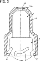
図3は、外面の、閉鎖位置を示したソケットにかぶせられるキャップの断面図である。
図4は、内栓の第二の実施態様の断面図である。
図5aと5bは、それぞれ閉鎖位置と開放位置にある本発明による内栓の第三の実施態様を示す断面図である。
図1に示した内栓Eは、ここでは液体またはペースト状の物質Pが満たされた軟質袋で形成され、継手Dに気密に固定されたタンクRに取り付けられるものである。
袋Rは手で直接、あるいは継手Dと一体の支柱Mに摺動自在にとりつけられたパレットTによって加圧することができる。この様にして袋Rは硬質構造の内部に維持される。
本発明によれば、内栓Eは一方ではリングBを介して、袋Rの継手Dへの接続端11を、他方では噴出孔10を備えるソケット1を有する。
内栓Eはさらに、継手Dから噴出孔10までの、物質Pのための流路を配置してソケット1内部に格納された、移動閉塞器2を備えている。
閉塞器2はその外端に、噴出孔10とともに排出弁を形成する栓20を担持しているロッド21から成る。
ロッド21の内端は閉塞器の復帰手段と共働する硬質横断壁22を備えている。壁22はロッド21と1つの部品のみで実現することによって、あるいは図1と図2に示したごとく、その中にロッド21の内端が係合した、別個の部品として形成された締め付けスリーブ24によって担持されて、ロッド21と連結されている。
図示した実施態様において、ロッド21は軸方向で、壁22とともに、流入弁を形成する弾性変形自在な周縁リップ23によってソケット1の内壁の方向に放射状に延長する周縁肩部22aを形成する。リップ23は壁22およびスリーブ24と1つの部品のみで実現されてクラウンを形成する。弁の閉鎖位置において、リップ23はこのようにして、物質のための流路をタンクRと連通することのできるソケット1の先端側11に位置する上流側室と、孔10によって、外部と連通することのできる下流側室に気密に分割する。
この様にしてリップ23は上流側端によってロッド21に連結された同軸クラウンを形成し、一方下流側の自由端は、図1に示した閉鎖位置において、ソケット1の内壁に密着している。
閉塞器2は、ここでは、バネで形成された復帰手段を備えている。
復帰バネ3はロッド21を同軸に囲繞し、その後部端螺旋が肩部22aに当接して、それによって、可動閉塞器2を閉鎖位置に復帰させる。バネ3の前部端螺旋は、バネの特性値に応じて決められた長さだけ孔10の近傍のソケット1の内壁上に延長している、長手方向リブ12の上に当接している。
栓20は本体20aによって構成され、後者の側面は、閉鎖位置において、噴出孔10の内縁10aに密着して、それによって排出弁の弁座を形成している。このようにして2つの円錐形表面の間に気密な接触が実現される。別の実施態様において(図示されていない)、噴出孔10の内縁10aに実現した環状のリングを備えることもできる。このとき接触は栓20の本体20aの側面とこのリング間に確保され、このようにして円形の線に縮小されて、気密な接触が強化される。本体20aはソケット1の外に、前方に突出している頭部20bによって延長している。
好適には、噴出孔10は栓20の本体20aの形状に対応した円錐台形の形状を有する。
ソケット1は弾頭形の形状を有し、栓20の頭部20bは曲率が弾頭形の外観の連続性を保証するように決定された曲線形状を有する。
物質Pの圧力が栓20の本体20aの側面に働いたとき、閉塞器2は柱20が噴出孔10と嵌合し、その中に気密に保持されている後方閉鎖位置から前方に移動する。
この移動は掛かった圧力が推力の働きによって圧縮される弦巻バネ3の風袋秤量によって決定される限度値を超えたときにしか起こらない。物質Pはこのときリップ23を弾性変形させ、壁22を側面方向に迂回して下流側室内に侵入する。ついで、下流室の内部で、物質Pはバネ3の螺旋を横断して、ソケット1の内壁とスリーブ24および/または閉塞器2のロッド21の間の空間内で、噴出孔10に向けられ、栓20の本体20aを押し、迂回してから外に排出される。
噴出機構は、例えば、バネ3が気密性を強化するように閉塞器の閉鎖位置でなおわずかに圧縮されるように構成することによって調節できる。
この場合、柱20の本体20aの側面が噴出孔10の内縁10aに対して強制的に当接することによって閉塞器が前方に向かって閉鎖位置に保持される。
変型によれば、ソケット1の接続先端11または継手Dがその内壁上に閉塞器が閉鎖位置に戻るときに壁22のための後方当たり止めを形成するリブ11aを具備する構成とすることができる。
図示した変型において、リブ11aは継手Dの縁によって形成されている。
図3において、内栓はソケット1にかぶせるための取り外し自在なキャップ4を備えている。
キャップ4の頂上は壁が肉薄になったへこみ部分40を備えて、その内面が、栓20の頭部20bに当接して閉鎖の気密性を保証する。
キャップ4は、例えば、外側で、ソケット1の接続先端11の上に、あるいは外側リングの上にねじ込まれるか、あるいは、図3に示したごとく、硬質タンクRの壁の上に直接ねじ込まれる。
このため、タンクRの壁は、締め付けを確保するために、キャップ4の内壁に配置された、対応するリブ41と共働するネジ山を形成するリブNを備えている。
リブ41とNの位置と形状は、締め付けの終わりにへこみ部分40が栓20に当接するように決定される。
必要に応じて、キャップは容器Rの上部に当接する内部補剛要素42(図5a、5b参照)を備えている。
図4の実施態様において、流入弁の周縁リップ23を担持する壁22は爪25によってタンクRに向かって延長し、爪はスリーブ5内に嵌合し、スリーブ自体も継手D内に格納されて、タンクRの内部に突出している。
必要ならば、スリーブ5はソケット1の接続先端11または継手Dの内壁に連結されている(図5a、5b参照)。ここでは、接続先端11は継手Dの上にねじ込まれ、周縁カラー11aを備えている。
スリーブ5は壁22の後面24に正対して配置された肩部50を具備する。
この実施態様において、バネ3の前端はソケット1の頂上の内壁に配置された環状の溝13の底に当接する。溝13はその内縁で、ロッドが軸方向に運動したときにロッド21の案内を保証するカラー14によって限定される。カラー14の自由内縁14aはこれによって、スリーブがロッド21とともに軸方向に移動したときに、スリーブ24の当たり止めの役割を果たす。リップ23が長い場合(図5a、5bの実施態様の場合のように)、閉塞器2が開放位置にあるときにその自由端は少なくとも部分的に溝13内に嵌合できる。
タンクR内の圧力が高まったとき、物質Pは一方ではスリーブ5によって、他方では爪25によって限定された環状の自由空間を通って、ソケット1の上流側室に到達する。
この空間は狭いが、物質Pの粘性に適しているので、タンクRからソケット1の内部空間に向かうその流速を抑えることができる。
つぎに、物質はリップ23を変形して、ソケット1の下流側の室内に侵入する。
ついで栓20に推力が働いて、軸方向に孔10の外に移動する。この運動によってバネ3が圧縮され、それによって外部に向かってロッド21とカラー14の間に物質Pのための通路が形成される。
図5a、5bに示した実施態様において、横断壁22は弾性変形可能で、ソケット1の接続先端11に保持され、それによって閉塞器2の弾性復帰手段を形成している。壁22とリップ23は、ロッド21の狭隘部21aの上に締め付けられた中央締め環26によって結合されている。
壁22はタンクRとソケットの上流側室の間の物質Pの通過のために流路を配置するように穴が開けられている。The present invention relates to a dispensing plug for liquid or pasty substances.
There is already a dispensing tap that can be pressurized to attach to the tank.
Generally, the discharge valve is positioned inside a pump mechanism that ensures the discharge of material. This pump is activated by a push button that forms an inner plug / diffuser.
However, because the inner plug is mounted downstream of the discharge valve, a certain amount of material between the valve and the outlet hole of the inner plug remains exposed to air.
In certain fields of application, in particular pharmaceuticals and cosmetics, this amount of unprotected material can be contaminated with bacteria or dry out and block the ejection duct.
In such a state, the substance left in the tank cannot be used.
In order to eliminate such drawbacks, CH-A-178923 has a tank connection tip on one side, and a sleeve provided with an ejection hole,
・ Estimated return of the movable occluder to a closed position where the stopper forms an exhaust valve with the ejection hole at the outer end, and a flow path for the substance at the inner end, and the stopper fits the ejection hole in an airtight manner. A movable occluder housed in said socket, comprising a rod having transverse walls cooperating with the means:
An internal plug consisting of
However, since the occluder is a manual operation, the differential pressure for opening and closing the discharge valve is low (about 0.1 bar).
As a result, the airtightness after the occluder is loosened and the discharge valve is closed is not sufficiently high, so that the intake of air cannot be completely prevented.
In such a situation, there remains a risk of contamination of the material.
The present invention aims to solve this technical problem in a sufficient manner by improving the tightness of the inner plug for use in sterile materials.
This object is achieved according to the invention in an internal plug for attachment to a tank that can be pressurized,
・ Tank connection tip, socket with ejection hole,
・ Estimated return of the movable occluder to the closed position where the stopper forms an outlet valve with the ejection hole at the outer end and the flow path for the substance at the inner end, and the stopper fits the outlet hole in an airtight manner. A movable occluder housed in said socket, comprising a rod having transverse walls cooperating with the means:
And further comprising an inflow valve comprising a deformable peripheral lip that hermetically divides the flow passage of the material around the rod into an upstream chamber and a downstream chamber. .
According to an advantageous embodiment, the lip is connected to a rod, the free end of which is in close contact with the inner wall of the socket in the closed position of the valve.
According to a particular embodiment, the lip is carried by a crown coaxial with the rod.
Preferably, the transverse wall is realized with only one piece with the crown.
According to another embodiment, the upstream end of the lip is connected to the rod.
According to a further embodiment, the transverse wall is elastically deformable and is held by its periphery at the connection end of the socket, forming an elastic return means for the occluder.
According to an advantageous feature, the rod forms an axial shoulder with the transverse wall in the axial direction.
According to a variant embodiment, the elastic return means comprises a chord spring that surrounds the rod of the occluder with the rear end abutting the shoulder and the front end abutting the inner wall of the socket.
According to a particular feature of this variant, the front end of the spring bears against a longitudinal rib extending along the inner wall of the socket.
According to another feature of this variant, the front end of the spring rests in the bottom of the annular groove, which is arranged on the inner wall of the socket and whose inner edge is limited by the rod guide collar.
According to another embodiment, the plug first comprises a main body whose side faces are in close contact with the inner edge of the ejection hole in the closed position, and further a head that projects out of the socket.
According to a particular variant, the ejection holes have a frustoconical shape corresponding to the shape of the plug body. Otherwise, the inner edge of the ejection hole is provided with a shaped ring on which the side of the plug body will be in close contact when the plug is closed.
According to yet another embodiment, the socket has a warhead shape and the plug head has a curved shape whose curvature is determined to ensure continuity of the warhead appearance.
According to yet another feature, the connecting end of the socket has a rib on the inner wall that forms a stop for the transverse wall.
According to yet another feature, the rod is connected to a transverse wall and fits within a clamping sleeve carrying the wall.
Preferably, the inner plug further comprises a removable cap for covering the socket, the top of which abuts the plug by its inner surface to ensure the tightness of the closure.
Further, the transverse wall may be extended toward the tank by a claw fitted in a sleeve protruding inside the tank.
The internal plug according to the present invention has a combination of two valves that allows for tightness control, thus protecting the entire contents of the tank from any contact with the outside air and eliminating the risk of material alteration or bacterial infection. The The inner plug can be easily mounted on the tank, either directly or indirectly via a joint, from the inside or from the outside.
The material in the chamber upstream of the inner plug is effectively protected in the same way as when in the tank.
Two valves mounted on the same part operate in the same direction, but in a direction of movement along separate axes.
When the pressure is generated in the substance and in the tank and exceeds the threshold value, the occluder moves and the substance is ejected. Below this threshold, the occluder is in the closed position on the inner plug by actuation of the return means.
Furthermore, the structure of the inner plug prevents the material from being accidentally exposed or leaked. A cap over the socket and abutting the plug of the occluder keeps the plug in a closed position in close contact with the valve seat. This arrangement ensures the tightness of the inner plug even when pressure is unexpectedly generated in the substance in the tank.
The invention will become apparent upon reading the following description with reference to the accompanying drawings.
FIG. 1 is a longitudinal sectional view of a first embodiment of an inner plug according to the invention in a closed position and mounted on a tank.
FIG. 2 is a longitudinal sectional view of the inner plug of FIG. 1 in the open position.
FIG. 3 is a cross-sectional view of the cap that is placed on the outer surface of the socket in the closed position.
FIG. 4 is a cross-sectional view of a second embodiment of the inner plug.
5a and 5b are cross-sectional views showing a third embodiment of the inner plug according to the present invention in the closed position and the open position, respectively.
The inner plug E shown in FIG. 1 is formed of a soft bag filled with a liquid or paste-like substance P and is attached to a tank R that is airtightly fixed to the joint D.
The bag R can be pressurized by hand or by a pallet T slidably attached to a support M integral with the joint D. In this way, the bag R is maintained inside the hard structure.
According to the invention, the inner plug E has on the one hand a
The inner plug E further includes a
The
The inner end of the
In the embodiment shown, the
In this way, the
Here, the
The
The
Preferably, the
The
When the pressure of the substance P acts on the side surface of the
This movement only occurs when the applied pressure exceeds a limit value determined by the tare weight of the
The ejection mechanism can be adjusted, for example, by configuring it so that the
In this case, the obturator is held in the closed position toward the front by forcibly contacting the side surface of the
According to the variant, the
In the illustrated variant, the
In FIG. 3, the inner plug is provided with a
The top of the
The
For this purpose, the wall of the tank R is provided with ribs N which are arranged on the inner wall of the
The positions and shapes of the
Optionally, the cap includes an internal stiffening element 42 (see FIGS. 5a and 5b) that abuts the top of the container R.
In the embodiment of FIG. 4, the
If necessary, the
The
In this embodiment, the front end of the
When the pressure in the tank R increases, the substance P reaches the upstream chamber of the
Although this space is narrow, since it is suitable for the viscosity of the substance P, the flow velocity from the tank R toward the internal space of the
Next, the substance deforms the
Then, a thrust is applied to the
In the embodiment shown in FIGS. 5 a and 5 b, the
The
Claims (1)
タンク(R)への接続先端(11)と噴出孔(10)とを備えたソケット(1)と、
ソケット(1)の内部に、物質(P)のための流路を形成するように格納された可動閉塞器(2)と、
可動閉塞器(2)の弾性復帰手段(3)とを有し、
さらに、次の特徴を備えた、内栓。
・可動閉塞器(2)は、ロッド(21)と、弾性変形自在な周縁リップ(23)から成る流入弁とを有している。
・ロッド(21)の外端は、噴出孔(10)とともに排出弁を形成する栓(20)を構成し、ロッド(21)の内端は、可動閉塞器(2)の弾性復帰手段(3)と共働する横断壁(22)を支えている。
・流入弁は、物質(P)のための流路内に配置され、ソケット(1)の内部空間を、上流の室と下流の室に気密に分割する。In an inner plug for dispensing a liquid or pasty substance (P) for attachment to a tank (R) that can be pressurized,
A socket (1) having a connection tip (11) to the tank (R) and an ejection hole (10);
A movable occluder (2) stored within the socket (1) to form a flow path for the substance (P);
Elastic return means (3) of the movable occluder (2),
Furthermore, an inner plug having the following characteristics.
The movable occluder (2) has a rod (21) and an inflow valve composed of an elastically deformable peripheral lip (23).
- the outer end of Rod (21) constitutes a plug (20) forming a discharge valve with injection holes (10), the inner end of Rod (21), the elasticity of the movable occluder (2) return means (3) and cooperating transverse wall (22) of the supporting Eteiru.
· Flow Iriben is disposed in the flow path for the material (P), to divide the interior space of the socket (1), hermetically upstream chamber and the downstream chamber.
Applications Claiming Priority (3)
| Application Number | Priority Date | Filing Date | Title |
|---|---|---|---|
| FR9600120A FR2743353B1 (en) | 1996-01-08 | 1996-01-08 | DISPENSING TIP FOR LIQUID OR PASTY PRODUCTS |
| FR96/00120 | 1996-01-08 | ||
| PCT/FR1997/000021 WO1997025253A1 (en) | 1996-01-08 | 1997-01-07 | Nozzle for dispensing a liquid or pasty material |
Related Child Applications (1)
| Application Number | Title | Priority Date | Filing Date |
|---|---|---|---|
| JP2005324941A Division JP2006096420A (en) | 1996-01-08 | 2005-11-09 | Liquid or paste-like matter dispensing inner nozzle |
Publications (2)
| Publication Number | Publication Date |
|---|---|
| JP2000502978A JP2000502978A (en) | 2000-03-14 |
| JP3834061B2 true JP3834061B2 (en) | 2006-10-18 |
Family
ID=9487941
Family Applications (2)
| Application Number | Title | Priority Date | Filing Date |
|---|---|---|---|
| JP52491397A Expired - Fee Related JP3834061B2 (en) | 1996-01-08 | 1997-01-07 | Dispensing plug for liquid or pasty substances |
| JP2005324941A Pending JP2006096420A (en) | 1996-01-08 | 2005-11-09 | Liquid or paste-like matter dispensing inner nozzle |
Family Applications After (1)
| Application Number | Title | Priority Date | Filing Date |
|---|---|---|---|
| JP2005324941A Pending JP2006096420A (en) | 1996-01-08 | 2005-11-09 | Liquid or paste-like matter dispensing inner nozzle |
Country Status (9)
| Country | Link |
|---|---|
| US (1) | US5992764A (en) |
| EP (1) | EP0874761B1 (en) |
| JP (2) | JP3834061B2 (en) |
| AT (1) | ATE185759T1 (en) |
| DE (1) | DE69700650T2 (en) |
| ES (1) | ES2139434T3 (en) |
| FR (1) | FR2743353B1 (en) |
| PT (1) | PT874761E (en) |
| WO (1) | WO1997025253A1 (en) |
Families Citing this family (15)
| Publication number | Priority date | Publication date | Assignee | Title |
|---|---|---|---|---|
| US6382204B1 (en) | 1999-10-14 | 2002-05-07 | Becton Dickinson And Company | Drug delivery system including holder and drug container |
| US6481645B1 (en) | 2000-05-22 | 2002-11-19 | Shurflo Pump Mfg. Company, Inc. | Condiment dispensing nozzle apparatus and method |
| US6698629B2 (en) | 2001-05-10 | 2004-03-02 | Shurflo Pump Manufacturing Co., Inc. | Comestible fluid dispensing tap and method |
| US6685109B2 (en) * | 2001-09-24 | 2004-02-03 | Daniel Py | System and method for a two piece spray nozzle |
| JP4574236B2 (en) * | 2004-06-07 | 2010-11-04 | ロート製薬株式会社 | Container spout structure and packaging container |
| DE102005057822B4 (en) * | 2005-12-03 | 2009-08-13 | Lindal Ventil Gmbh | Spray cap for a pressure vessel provided with a dispensing valve |
| FR2922808B1 (en) * | 2007-10-30 | 2010-02-19 | Michelin Soc Tech | DEVICE FOR THE EXTRUSION OF A GUM BAND. |
| GB2459852B (en) * | 2008-05-06 | 2011-02-16 | Toly Products | Compact liquid cosmetics |
| KR20100029921A (en) * | 2008-09-09 | 2010-03-18 | 최민철 | Tube case |
| FR2941682B1 (en) * | 2009-02-03 | 2016-03-11 | Sivel | DEVICE FOR PACKAGING AND DISPENSING A CLEAN OR STERILE PRODUCT WITH SELF CLEANING TIP |
| CN102438914B (en) | 2009-05-22 | 2015-03-04 | 大塚制药株式会社 | Container for eye drops |
| TW201202101A (en) * | 2010-07-01 | 2012-01-16 | guo-zhong Fang | Pressing type storage container |
| KR101278879B1 (en) * | 2012-04-06 | 2013-06-26 | (주)연우 | Tube vessel |
| JP5652796B1 (en) * | 2013-06-13 | 2015-01-14 | 東京パーツ株式会社 | Chemical application tool |
| CN105750159B (en) * | 2014-12-15 | 2018-02-23 | 南通中集特种运输设备制造有限公司 | Gluing device |
Family Cites Families (16)
| Publication number | Priority date | Publication date | Assignee | Title |
|---|---|---|---|---|
| FR627319A (en) * | 1927-01-10 | 1927-10-01 | Tube closure | |
| US1862794A (en) * | 1931-11-19 | 1932-06-14 | Porter P Lamb | Collapsible tube closure |
| US1888007A (en) * | 1932-04-04 | 1932-11-15 | Jr Charles T Millis | Sanitary self-closing cap |
| US2039952A (en) * | 1933-09-11 | 1936-05-05 | John H Donnelly | Closure |
| CH178923A (en) * | 1934-10-05 | 1935-08-15 | Anubis Ag | Automatic tube closure. |
| US2060455A (en) * | 1934-11-27 | 1936-11-10 | Wittner Michael | Dispensing device |
| US2168297A (en) * | 1937-02-05 | 1939-08-01 | Voke Carl Edward | Closure |
| US2106046A (en) * | 1937-08-06 | 1938-01-18 | Sidney D Barlow | Marking implement |
| US2140247A (en) * | 1938-03-31 | 1938-12-13 | Pazdernick William | Automatic tube closure |
| FR967501A (en) * | 1948-06-10 | 1950-11-06 | Improvements to dispenser caps adaptable to flexible tubes containing pasty products | |
| US2815247A (en) * | 1955-09-21 | 1957-12-03 | Bosch Arma Corp | Fuel injection nozzle |
| US3379490A (en) * | 1965-11-01 | 1968-04-23 | Schwartzman Gilbert | Narrow line applicator |
| ES419697A1 (en) * | 1972-10-18 | 1976-03-16 | Ivanov Mantchev | Valvular liquid dispensing closure |
| US3863844A (en) * | 1973-05-02 | 1975-02-04 | Fire Task Force Innovations In | Automatic fire nozzle with automatic control of pressure and internal turbulence combined with manual control of variable flow and shape of stream produced |
| GB2048827A (en) * | 1979-05-04 | 1980-12-17 | Chappell A | Metering device |
| FR2662424B1 (en) * | 1990-05-28 | 1992-09-04 | Oreal | DISPENSING ASSEMBLY OF A PRODUCT, COMPRISING A DISTRIBUTION NOZZLE WITHOUT AIR INTAKE. |
-
1996
- 1996-01-08 FR FR9600120A patent/FR2743353B1/en not_active Expired - Fee Related
-
1997
- 1997-01-07 ES ES97900238T patent/ES2139434T3/en not_active Expired - Lifetime
- 1997-01-07 DE DE69700650T patent/DE69700650T2/en not_active Expired - Lifetime
- 1997-01-07 EP EP97900238A patent/EP0874761B1/en not_active Expired - Lifetime
- 1997-01-07 PT PT97900238T patent/PT874761E/en unknown
- 1997-01-07 AT AT97900238T patent/ATE185759T1/en not_active IP Right Cessation
- 1997-01-07 JP JP52491397A patent/JP3834061B2/en not_active Expired - Fee Related
- 1997-01-07 WO PCT/FR1997/000021 patent/WO1997025253A1/en active IP Right Grant
- 1997-01-07 US US09/091,824 patent/US5992764A/en not_active Expired - Fee Related
-
2005
- 2005-11-09 JP JP2005324941A patent/JP2006096420A/en active Pending
Also Published As
| Publication number | Publication date |
|---|---|
| DE69700650D1 (en) | 1999-11-25 |
| JP2000502978A (en) | 2000-03-14 |
| PT874761E (en) | 2000-04-28 |
| WO1997025253A1 (en) | 1997-07-17 |
| US5992764A (en) | 1999-11-30 |
| ATE185759T1 (en) | 1999-11-15 |
| JP2006096420A (en) | 2006-04-13 |
| EP0874761A1 (en) | 1998-11-04 |
| FR2743353B1 (en) | 1998-03-27 |
| ES2139434T3 (en) | 2000-02-01 |
| EP0874761B1 (en) | 1999-10-20 |
| FR2743353A1 (en) | 1997-07-11 |
| DE69700650T2 (en) | 2000-07-06 |
Similar Documents
| Publication | Publication Date | Title |
|---|---|---|
| JP2006096420A (en) | Liquid or paste-like matter dispensing inner nozzle | |
| US20080135586A1 (en) | One way valve assembly | |
| US5454488A (en) | Apparatus for dispensing a semifluid medium from a container | |
| US4538745A (en) | Trigger sprayer | |
| US4694977A (en) | Fluid dispenser | |
| US6264067B1 (en) | Dispensing member actuating device, assembly, and method | |
| AR029511A1 (en) | DOSING SYSTEM WITH AN INTERNAL CLOSURE FOR REMOVABLE TRANSPORTATION AND AN EXTENDED POINT CONTAINING A VALVE THAT OPENS PRESSURE | |
| US5605257A (en) | Sterile liquid squeeze-bottle-type dispenser | |
| US6095376A (en) | Antibacterial device for spraying a liquid | |
| ES2025782T3 (en) | COMPRESSIBLE CHAMBER DISPENSING VALVE. | |
| MXPA01003061A (en) | Air intake valve arrangement. | |
| CN117615856A (en) | Trigger dispensing head with means for preventing leakage of product | |
| CZ20022186A3 (en) | Discharge head for compressible discharge device | |
| US11141750B2 (en) | Compact dispensing device | |
| US5655302A (en) | Shaving cream dispensing razor | |
| JP5227652B2 (en) | External air introduction mechanism of discharge container | |
| US20210146391A1 (en) | Liquid dispenser with bottle ventilation | |
| KR960010634Y1 (en) | Cosmetic vessel | |
| US3491921A (en) | Non-clogging aerosol valve | |
| WO2023067534A1 (en) | Trigger dispensing head with reduced piston chamber | |
| JPH1016998A (en) | Delivery container | |
| GB2372782A (en) | Nasal sprays | |
| JP2003071336A (en) | Check valve | |
| US5988231A (en) | Valve stem for transferring fluid between sealed containers | |
| JPH08143055A (en) | Discharging container |
Legal Events
| Date | Code | Title | Description |
|---|---|---|---|
| A131 | Notification of reasons for refusal |
Free format text: JAPANESE INTERMEDIATE CODE: A131 Effective date: 20040817 |
|
| A601 | Written request for extension of time |
Free format text: JAPANESE INTERMEDIATE CODE: A601 Effective date: 20041116 |
|
| A602 | Written permission of extension of time |
Free format text: JAPANESE INTERMEDIATE CODE: A602 Effective date: 20041227 |
|
| A521 | Request for written amendment filed |
Free format text: JAPANESE INTERMEDIATE CODE: A523 Effective date: 20050217 |
|
| A131 | Notification of reasons for refusal |
Free format text: JAPANESE INTERMEDIATE CODE: A131 Effective date: 20050809 |
|
| A521 | Request for written amendment filed |
Free format text: JAPANESE INTERMEDIATE CODE: A523 Effective date: 20051109 |
|
| TRDD | Decision of grant or rejection written | ||
| A01 | Written decision to grant a patent or to grant a registration (utility model) |
Free format text: JAPANESE INTERMEDIATE CODE: A01 Effective date: 20060704 |
|
| A61 | First payment of annual fees (during grant procedure) |
Free format text: JAPANESE INTERMEDIATE CODE: A61 Effective date: 20060721 |
|
| R150 | Certificate of patent or registration of utility model |
Free format text: JAPANESE INTERMEDIATE CODE: R150 |
|
| FPAY | Renewal fee payment (event date is renewal date of database) |
Free format text: PAYMENT UNTIL: 20100728 Year of fee payment: 4 |
|
| FPAY | Renewal fee payment (event date is renewal date of database) |
Free format text: PAYMENT UNTIL: 20100728 Year of fee payment: 4 |
|
| FPAY | Renewal fee payment (event date is renewal date of database) |
Free format text: PAYMENT UNTIL: 20110728 Year of fee payment: 5 |
|
| LAPS | Cancellation because of no payment of annual fees |