JP3832940B2 - Pulley pressure supply device for belt type continuously variable transmission for vehicle - Google Patents
Pulley pressure supply device for belt type continuously variable transmission for vehicle Download PDFInfo
- Publication number
- JP3832940B2 JP3832940B2 JP23507197A JP23507197A JP3832940B2 JP 3832940 B2 JP3832940 B2 JP 3832940B2 JP 23507197 A JP23507197 A JP 23507197A JP 23507197 A JP23507197 A JP 23507197A JP 3832940 B2 JP3832940 B2 JP 3832940B2
- Authority
- JP
- Japan
- Prior art keywords
- pulley
- oil
- driven
- drive
- supplied
- Prior art date
- Legal status (The legal status is an assumption and is not a legal conclusion. Google has not performed a legal analysis and makes no representation as to the accuracy of the status listed.)
- Expired - Fee Related
Links
Images


Landscapes
- Control Of Transmission Device (AREA)
- Pulleys (AREA)
- Transmissions By Endless Flexible Members (AREA)
Description
【0001】
【発明の属する技術分野】
本発明は、プーリ幅可変の一対のプーリ間にベルトを巻き掛けてなるベルト式変速機構を有した車両用ベルト式無段変速機のプーリ圧供給装置に関する。
【0002】
【従来の技術】
プーリ幅可変の一対のプーリと、この両プーリ間に巻き掛けたベルトから構成されたベルト式変速機構を備え、ベルトの滑りを生じない適切なプーリ推力圧(プーリ側圧)を適宜変化させ、ベルトの巻き掛け径を変えることによって無段変速を行うベルト式無段変速機が車両用等に用いられていることは周知である。この一対のプーリはドライブプーリとドリブンプーリとからなり、各プーリはそれぞれプーリ軸に固定された固定プーリ半体とプーリ軸の軸方向に移動可能な可動プーリ半体とから構成される。
【0003】
両プーリのプーリ幅の調整、すなわち可動プーリ半体の軸方向の移動量の調整は、可動プーリ半体と固定プーリ半体のシリンダ壁とに囲まれて形成されるシリンダ室に適宜所定のプーリ推力圧を供給することによって行われる。そして、この油圧を供給する油圧ポンプは、エンジンに直結した軸上に配設されたギヤにより常時駆動されている。
【0004】
【発明が解決しようとする課題】
ここで、例えばトルクコンバータを有し、これにより発進クラッチの機能を与えているベルト式無段変速機のように、ドリブンプーリからタイヤ車軸までの動力伝達経路中にクラッチ装置が設けられていない変速機の場合には、ドリブンプーリからタイヤ車軸までは機械的に連結しており、常に連動して作動する。このような変速機を有した車両において、例えばエンジンが故障したような場合に車両を牽引走行するときは、タイヤの回転はタイヤ車軸、ドリブンプーリを経てベルトへ伝達され、ベルトは両プーリ間を回転することとなる。このときエンジンは停止しており油圧ポンプは作動せずシリンダ室にプーリ推力圧が供給されないため、ベルトは両プーリ間に適切に保持されない状態で回転を続けるという問題があった。
【0005】
又、適切なプーリ推力圧を得るために、シリンダ室にスプリング等を設けることが考えられるが、必要十分なプーリ推力圧をそのスプリングにより得ようとすると、大きな設定荷重のスプリングが必要となり、スペース的にかなり困難である。
【0006】
本発明はこのような問題に鑑みてなされたものであり、エンジン停止状態で車両牽引を行う時にもシリンダ室にプーリ推力圧を供給して、ベルトが両プーリ間に適切に保持されない状態で回転することを防止できるベルト式無段変速機のプーリ圧供給装置を提供することを目的とする。
【0007】
【課題を解決するための手段】
上記の目的を達成するために、本発明に係るベルト式無段変速機のプーリ圧供給装置は、ドライブ側シリンダ室に供給されるプーリ圧によりプーリ幅を変更可能なドライブプーリ、ドリブン側シリンダ室に供給されるプーリ圧によりプーリ幅を変更可能なドリブンプーリ及びこれら両プーリ間に巻き掛けられたベルトとから構成されたベルト式無段変速機構と、ドライブプーリに駆動力を供給する駆動源と、ドリブンプーリの出力を車輪に伝達する出力伝達手段と、駆動源により駆動される第1油圧ポンプと、この駆動源が駆動しているときに、第1油圧ポンプからの吐出油を調圧制御するとともにこの調圧された油圧をドライブ側および前記ドリブン側シリンダ室へ供給する制御を行う油圧制御装置と、出力伝達手段の回転駆動力により駆動される第2油圧ポンプと、駆動源が停止して第1油圧ポンプが停止しているときに、第2油圧ポンプからの吐出油を油圧制御装置の作動制御に用いることなくドライブ側およびドリブン側シリンダ室へ直接供給させるプーリ圧供給制御手段とから構成される。
なお、プーリ圧供給制御手段が、ソレノイド式の油路切換手段を有し、駆動源が駆動しているときに、油路切換手段のソレノイドがオンとなってプーリ圧供給制御手段は第2油圧ポンプからの吐出油を第1油圧ポンプからの吐出油と合流させて油圧制御装置に供給させ、駆動源が停止しているときに、油路切換手段のソレノイドがオフとなってプーリ圧供給制御手段は第2油圧ポンプからの吐出油をドライブ側およびドリブン側シリンダ室へ直接供給させるように構成されるのが好ましい。
また、第2油圧ポンプからの吐出油を油圧制御装置の作動制御に用いることなくドライブ側およびドリブン側シリンダ室へ直接供給させる油路中に、ドライブ側およびドリブン側シリンダ室への油圧供給は行わせるがこれと逆の油の流れを阻止するチェックバルブが配設され、油圧制御装置からドライブ側およびドリブン側シリンダ室へ調圧された油圧を供給する油路中に、ドライブ側およびドリブン側シリンダ室への油圧供給は行わせるがこれと逆の油の流れを阻止するチェックバルブが配設される構成とするのが好ましい。
【0008】
上記構成によれば、駆動源が駆動しているときには、油圧制御装置により第1油圧ポンプからの吐出油が調圧制御されるとともにこの調圧された油圧をドライブ側および前記ドリブン側シリンダ室へ供給する制御が行われて、無段変速制御が行われ、一方、駆動源が停止して第1油圧ポンプが停止しているときには、プーリ圧供給制御手段により第2油圧ポンプからの吐出油が油圧制御装置の作動制御に用いることなくドライブ側およびドリブン側シリンダ室へ直接供給されるので、ベルトが両プーリ間に適切に保持されない状態で回転することを防止できる。
又、プーリ圧供給制御手段が、ソレノイド式の油路切換手段を有していれば、エンジン(駆動源)の駆動による発電器からの通電によりソレノイドがオン・オフされるので、駆動源が駆動しているときに、油路切換手段のソレノイドがオンとなってプーリ圧供給制御手段により第2油圧ポンプからの吐出油が第1油圧ポンプからの吐出油と合流されて油圧制御装置に供給され、駆動源が停止しているときに、油路切換手段のソレノイドがオフとなってプーリ圧供給制御手段により第2油圧ポンプからの吐出油がドライブ側およびドリブン側シリンダ室へ直接供給される。
さらに、第2油圧ポンプからの吐出油を両シリンダ室へ直接供給させる油路中に、両シリンダ室への油圧供給のみを許容するチェックバルブが配設され、油圧制御装置から両シリンダ室へ調圧された油圧を供給する油路中に、両シリンダ室への油圧供給のみを許容するチェックバルブが配設される構成とすれば、第2油圧ポンプからの吐出油を両シリンダ室へ直接供給しているときにこの吐出油が油圧制御装置側に流れるのが阻止されるとともに、第1油圧ポンプからの吐出油が油圧制御装置により調圧されて両シリンダ室へ供給されるときに第2油圧ポンプ側に流れるのが阻止される。
【0009】
【発明の実施の形態】
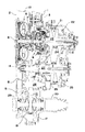
以下、本発明の好ましい実施形態について図を参照して説明する。図3及び4に本発明に係るプーリ圧供給装置を有したベルト式無段変速機の構成を示す。このベルト式無段変速機はハウジング1内にベルト式無段変速機構を有して構成され、このハウジング1は左端にエンジンフライホイールハウジングとの接合面2を有し、この接合面2がエンジンフライホイールに接合されるように変速機がエンジンに取り付けられる。このとき、エンジン出力シャフトEsと同軸上に第1軸S1が位置する。なお、以下の説明においては、変速機の回転シャフト、ギヤ等の各回転中心軸を第1軸S1〜第4軸S4として示すが、これは中心軸線を意味する。
【0010】
このベルト式無段変速機においては、ハウジング1内における第1軸S1上にトルクコンバータ5(インペラ5a、タービン5b及びステータ5cからなる)及び前後進切換機構4を並列に有する。エンジン出力シャフトEsはトルクコンバータ5のインペラ5aに接続され、トルクコンバータ5のタービン5bはタービンシャフト6(これは前後進切換機構4の入力シャフトでもある)と繋がる。なお、トルクコンバータ5は、エンジン出力シャフトEsとタービン5bとを直接接続可能なロックアップクラッチ5dを有する。 前後進切換機構4はダブルピニオンタイプのプラネタリギヤを有し、入出力部材(タービンシャフト6と第1シャフト23)を直結可能な前進用クラッチ11と、リングギヤを固定保持可能な後進用ブレーキ12とを備える。これら前進クラッチ11及び後進ブレーキ12を選択的に作動させて、タービンシャフト6に対して第1シャフト23を正転もしくは逆転させることが可能となっている。
【0011】
トルクコンバータケース13には第1油圧ポンプ3が取り付けられており、トルクコンバータ5の端部に配置されてインペラ5aに繋がったハブに設けられたギヤによりチェーン7を介して駆動される。第1油圧ポンプ3は、変速機下部のオイルパンに内蔵されたストレーナを介してオイルを吸引する。この吸引オイルは、変速機ケース下部及びバルブボディ内に構成されたサクション油路を経由し、ジョイントパイプ等を経て第1油圧ポンプ3に至る。第1油圧ポンプ3により吸引・吐出されたオイルは、トルクコンバータケース油路及び油圧制御回路を介して、変速に必要な制御油圧、トルクコンバータ系統、潤滑、冷却に使用される。
【0012】
第1シャフト23には、これと一体に形成された固定プーリ半体21aと、これに対向するとともに第1シャフト23上を軸方向に移動自在に配設された可動プーリ半体21bとからなるドライブプーリ21が配設されている。可動プーリ半体21bの側方には、固定プーリ半体21aに結合されたシリンダ壁12aにより囲まれてドライブ側シリンダ室22が形成されており、ドライブ側シリンダ室22内に供給される油圧、すなわちプーリ推力圧(特許請求の範囲のプーリ圧に相当)を制御することにより、可動プーリ半体21bを軸方向に移動可能である。
【0013】
第1軸S1から所定距離だけ離れて平行に延びる第2軸S2上には回転自在に第2シャフト27が配設されており、この第2シャフト27と一体に形成された固定プーリ半体25aと、これに対向するとともに第2シャフト27上を軸方向に移動自在に配設された可動プーリ半体25bとからドリブンプーリ25が構成されている。可動プーリ半体25bの側方には、固定プーリ半体25aに結合されたシリンダ壁により囲まれてドリブン側シリンダ室26が形成されており、ドリブン側シリンダ室26内に供給される油圧、すなわちプーリ推力圧を制御することにより、可動プーリ半体25bを軸方向に移動可能である。
【0014】
ドライブプーリ21とドリブンプーリ25とには金属製のVベルト24が巻き掛けられてベルト式無段変速機構が構成されており、ドライブプーリ21の回転がVベルト24を介してドリブンプーリ25に伝達される。このとき、両プーリ21,25の可動プーリ21a,25aを移動させてプーリ幅を調整することにより、両プーリ21,25におけるベルトの巻き掛け半径を任意に調整することができ、両プーリ21,25間での減速比を無段階に調整することができる。
【0015】
ドリブンプーリ25の左側には第1ギヤ14が第2シャフト27に結合して配設されている。第2軸S2から所定距離離れて平行に延びる第3軸S3上には第3シャフト28が回転自在に配設され、第3シャフト28には第2ギヤ15及び第3ギヤ16が一体に形成されている。第1ギヤ14は第2ギヤ15と噛合する。又、第3軸S3から所定距離離れて平行に延びる第4軸S4上にはディファレンシャル機構18が配設されており、このディファレンシャル機構18に結合配設された第4ギヤ17が第3ギヤ16と噛合する。このように、第1〜第4ギヤ14,15,16,17により動力伝達ギヤ列が構成されており、ドリブンプーリ25の回転はこの動力伝達ギヤ列を介してディファレンシャル機構18に伝達される。
【0016】
前記第3シャフト28の左方のハウジング1上には、第2油圧ポンプ8がボルト結合されるとともに、この第2油圧ポンプ8の回転軸が第3シャフト28にスプライン嵌合しており、第3シャフト28の回転駆動力を受けて第2油圧ポンプ8は駆動される。
【0017】
ディファレンシャル機構18には左右のアクスルシャフト29,30が繋がっており、ディファレンシャル機構18に伝達された動力はここで分割されて左右のアクスルシャフト29,30を介して左右の車輪(図示せず)に伝達される(ドリブンプーリ25の後前記動力伝達ギヤ列を経てアクスルシャフト29、30までの動力伝達機構が特許請求の範囲の出力伝達手段に相当する)。
【0018】
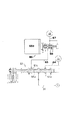
次に、上記構成の無段変速機に用いられる油圧制御装置について図1及び図2の油圧回路図を参照して説明する。なお、この回路図において丸囲み数字▲1▼同士が繋がり、×印はその部分がドレンに繋がっていることを意味する。
【0019】
エンジンの回転力を受けて駆動される第1油圧ポンプ3の吐出油は、油路32を介して高圧レギュレータバルブ41に供給されるとともに、油路36を介してレデューシングバルブ58に供給される。レジューシングバルブ58においてはほぼ一定の油圧を有したライン圧PMOD を作り出し、このライン圧を有した作動油を、油路31、37a,37b,37cに供給する。
【0020】
油路37aは高低圧コントロールバルブ45に繋がる。この高低圧コントロールバルブ45はリニアソレノイド45aを有し、リニアソレノイド45aへの通電電流が制御され、このリニアソレノイド45aからスプール45bに作用する押圧力が制御されることにより、油路37aから供給されるライン圧PMOD を調圧してこの押圧力に対応した制御背圧PHLC を油路35a,35bに供給する。この制御背圧PHLC は油路35aを介して低圧レギュレータバルブ43の右端油室43bに供給され、スプール43aを左方に押圧するように作用する。又、上記制御背圧PHLC は、油路35bを介して高圧コントロールバルブ47の右端油室47b及び第1中間油室47cに供給され、それぞれスプール47aを左方及び右方に押圧するように作用する。
【0021】
高圧レギュレータバルブ41は、第1油圧ポンプ3から油路32を介して供給される作動油圧を調圧し、高圧コントロール圧PHを油路33a,33bに供給する。この高圧コントロール圧PHは、油路33aを介してシフトバルブ53に供給されるとともに、油路33bを介して低圧レギュレータバルブ43に供給される。更に、高圧コントロール圧PHは高圧コントロールバルブ47の左端油室47dに繋がる油路33cにも供給される。
【0022】
高圧コントロールバルブ47の第2中間油室47eには、ライン圧PMOD が供給される油路37cが接続されている。この油路37cはオリフィス56を有するとともにオリフィス56の下流側においてソレノイドバルブ55に繋がっており、ソレノイドバルブ55のオン・オフ作動により、第2中間油室47eへのライン圧PMOD の供給制御がなされる。高圧コントロールバルブ47は、右端油室47b及び第1中間油室47cに供給される制御背圧PHLC 及び第2中間油室47eに供給されるライン圧PMOD によってスプール47aの位置制御がなされ、油路33cから供給された高圧コントロール圧PHを調圧して作られた油圧を、油路33dを介して高圧レギュレータバルブ41の右端油室41bに背圧として供給する。
【0023】
低圧レギュレータバルブ43は、制御背圧PHLC を受けて、油路33bから供給される高圧コントロール圧PHを調圧し、低圧コントロール圧PLを油路34に供給する。この低圧コントロール圧PLは、油路34から分岐した油路34a,34bを介してシフトバルブ53へに供給される。
【0024】
シフトコントロールバルブ51は、リニアソレノイド51aを有し、リニアソレノイド51aへの通電電流が制御され、このリニアソレノイド51aからスプール51bに作用する押圧力が制御されることにより、油路37bから供給されるライン圧PMOD を調圧してこの押圧力に対応したシフトコントロール圧PSVを油路38に供給する。このシフトコントロール圧PSVはシフトバルブ53の左端油室53cに供給され、スプール53aを右方に押圧するように作用する。
【0025】
シフトバルブ53は、スプール53aの位置に応じて高及び低圧コントロール圧PH,PLを、油路39a,39bを介してドライブ側及びドリブン側シリンダ室22,26に適宜振り分け供給する制御を行う。ここでスプール53aは、スプリング53bにより左方に押され、左端油室53cに供給されたシフトコントロール圧PSVを受けて右方に押される。このため、シフトコントロール圧PSVを制御することによりスプール53aの位置制御を行うことができ、その結果、ドライブ側及びドリブン側シリンダ室22,26内の油圧(プーリ推力圧)を制御してベルト機構10における減速比を無段階に制御することができる。
【0026】
一方、レデューシングバルブ58から油路31に供給されたライン圧PMOD は、マニュアルバルブ61に供給される。マニュアルバルブ61は、運転席(図示せず)のシフトレバーとコントロールケーブルを介して繋がっており、運転者の手動操作によって作動される。手動操作位置としては、P,R,N,D,S,Lの6位置があり、この操作位置に応じてマニュアルバルブ61のスプール61aは図示の対応位置に移動される。なお、図においてはスプール61aがN(ニュートラル)位置にある状態を示している。このマニュアルバルブ61の第1油室61bは、油路64を介してそのまま前進クラッチ11に繋がり、第2油室61cは、油路63を介して後進ブレーキ制御バルブ65に繋がっている。なお、後進ブレーキ制御バルブ65には、後進ブレーキ12に繋がる油路67が接続されている。
【0027】
このマニュアルバルブ61は、スプール61aがP,N位置にあるときは、油路63及び油路64をともにドレンに繋げる。このため、前進クラッチ11及び後進ブレーキ12はいずれも係合作動しない。又、スプール61aがD,S,L位置にあるときは、油路63をドレンに繋げるとともに油路31から供給されるライン圧PMOD を油路64に供給する。このため、後進ブレーキ12は解放され、前進クラッチ11が係合作動する。更に、スプール61aがR位置にあるときは、油路64をドレンに繋げるとともに油路31から供給されるライン圧PMOD を油路63に供給する。このため、前進クラッチ11は解放され、後進ブレーキ12は次に説明する後進ブレーキ制御バルブ65の作動により係合・解放制御される。
【0028】
後進ブレーキ制御バルブ65は、リニアソレノイド65aを有し、リニアソレノイド65aの押力がスプール66に作用する。このため、油路63を介して供給されるライン圧PMOD はリニアソレノイド65aの通電電流に応じて調圧されて後進ブレーキ制御圧Prvが作り出され、この後進ブレーキ制御圧Prvが油路67を介して後進ブレーキ27に供給される。このことから分かるように、後進ブレーキ制御バルブ65により、すなわちリニアソレノイド65aへの通電電流を制御することにより、後進ブレーキ27の係合制御を行うことができる。
【0029】
このように構成された制御装置において、前進クラッチ11又は後進ブレーキ12を係合作動させれば、車両は走行することができ、更に、制御油圧PSVを制御してシフトバルブ53のスプール53aの位置制御を行えば、ドライブ側及びドリブン側シリンダ室22,26内のプーリ推力圧を制御して変速制御を行うことができる。
【0030】
又、第3シャフト28の回転駆動力を受けて駆動される第2油圧ポンプ8の吐出油は、油路72を介してソレノイド式方向制御バルブ71へ供給される。このソレノイド式方向制御バルブ71は、通電がオンのときには第2油圧ポンプ8からの吐出油を油路32と合流する油路75へ供給する。一方、通電がオフのときには第2油圧ポンプ8からの吐出油を油路33aへ合流する油路73、及び油路34へ合流する油路74を介してシフトバルブ53へ供給する。なお、油路72には油路72aが分岐してリリーフバルブ76が設けられており、第2油圧ポンプ8からの油圧が設定圧以上のときはここからリリーフされる。又、油路73、74及び油路75にはそれぞれチェックバルブが設けられており、第1油圧ポンプ3からの吐出油がソレノイド式方向制御バルブ71方向へ流入しないようになっている。
【0031】
これらソレノイド式方向制御バルブ71を含む油圧制御装置(特許請求の範囲のプーリ圧供給制御手段に相当)により、通常走行時、すなわちエンジン駆動により車両が走行しているときには、エンジンにより駆動される発電機よりソレノイド式方向制御バルブ71への通電がなされ、第2油圧ポンプ8の吐出油は油路75から油路32へ合流して第1油圧ポンプ3の補助的機能を果たす。一方、車両牽引時、すなわちエンジンは停止してソレノイド式方向制御バルブ71への通電がなされず、タイヤが強制的に駆動されているときには、第2油圧ポンプ8の吐出油はシフトバルブ53を経てプーリ推力圧としてドライブ側及びドリブン側シリンダ室22、26へ供給される。
【0032】
このようにドライブ側及びドリブン側シリンダ室22、26にプーリ推力圧が供給されるので、車両牽引時にVベルト24が両プーリ21、25間に適切に保持されない状態で回転することを防止できる。又、ソレノイド式方向制御バルブ71を用いたことで、第2油圧ポンプ8からの油路の切り換え制御がエンジンの駆動或いは停止に応じて自動的になされるので確実である。
【0033】
ドライブ及びドリブン側シリンダ室22、26のプーリ推力圧は構造簡単化のため同圧に設定されるが、ドライブ側がドリブン側よりも高圧となるように設定してもよい。この場合はドライブプーリ21側のベルト径がドリブンプーリ25側の径よりも大きくなり、従ってドライブプーリ21の回転数はドリブンプーリ25の回転数よりも小さくなるので、プラネタリギヤユニットの保護のためには有効である。又、油路72aに設けられたリリーフバルブ76によりリリーフされた余剰吐出油を潤滑油路へ供給する構成としてもよい。
【0034】
なお、上記実施例では、通常走行時には第2油圧ポンプ8の吐出油を油路75へ供給して第1油圧ポンプ3の補助的役割を果たす構成となっているが、油路75は油タンクへ直結してドレンするようにしてもよい。
【0035】
又、上記構成の代わりに、第3シャフト28と第2油圧ポンプ8との間に、手動により動力断続を行える動力断続スイッチを設ける構成としても良い。この場合、車両牽引時には手動により動力断続スイッチを操作して動力接続状態とし、第3シャフト28により第2ポンプ8を駆動し、その吐出油がシフトバルブ53に供給されるようにする。一方、通常走行をするときには手動により操作して動力遮断状態とし、第2ポンプ8が第3シャフト28の回転を妨げないようにする。これにより前記ソレノイド式方向制御バルブ71を用いる構成と同様、車両牽引時にVベルト24が両プーリ21、25間に適切に保持されない状態で回転することを防止することができる。
【0036】
【発明の効果】
以上のように、本発明に係るベルト式無段変速機のプーリ圧供給装置によれば、プーリ圧供給制御手段により、車両牽引時には出力伝達手段の回転駆動力により駆動される第2油圧ポンプからの吐出油がプーリ圧としてドライブ側及びドリブン側シリンダ室へ供給されるので、ベルトが両プーリ間に適切に保持されない状態で回転することを防止できる。
【0037】
又、プーリ圧供給制御手段が、エンジンの駆動による発電器からの通電によりオン・オフされるソレノイド式の油路切換手段を有していれば、上記制御がエンジンの駆動或いは停止に応じて自動的になされるので確実である。
【図面の簡単な説明】
【図1】本発明のプーリ圧供給構造を有したベルト式無段変速機の全体構成を示す断面図である。
【図2】本発明のプーリ圧供給構造を有したベルト式無段変速機における動力伝達経路構成を示すスケルトン図である。
【図3】本発明のプーリ圧供給構造を構成する油圧制御回路図である。
【図4】本発明のプーリ圧供給構造を構成する油圧制御回路図である。
【符号の説明】
3 第1油圧ポンプ
8 第2油圧ポンプ
21 ドライブプーリ
24 Vベルト
25 ドリブンプーリ
71 ソレノイド式方向制御バルブ[0001]
BACKGROUND OF THE INVENTION
The present invention relates to a pulley pressure supply device for a belt type continuously variable transmission for a vehicle having a belt type transmission mechanism in which a belt is wound between a pair of pulleys having variable pulley widths.
[0002]
[Prior art]
A belt-type transmission mechanism composed of a pair of pulleys with variable pulley widths and a belt wound between the two pulleys, and appropriately changing an appropriate pulley thrust pressure (pulley side pressure) that does not cause belt slippage. It is well known that a belt-type continuously variable transmission that performs a continuously variable transmission by changing the winding diameter of the vehicle is used for a vehicle or the like. The pair of pulleys includes a drive pulley and a driven pulley, and each pulley includes a fixed pulley half fixed to the pulley shaft and a movable pulley half movable in the axial direction of the pulley shaft.
[0003]
The adjustment of the pulley width of both pulleys, that is, the adjustment of the amount of movement of the movable pulley half in the axial direction, is appropriately performed in a cylinder chamber formed by being surrounded by the movable pulley half and the cylinder wall of the fixed pulley half. This is done by supplying thrust pressure. The hydraulic pump for supplying the hydraulic pressure is always driven by a gear disposed on a shaft directly connected to the engine.
[0004]
[Problems to be solved by the invention]
Here, for example, a belt-type continuously variable transmission having a torque converter and thereby providing a starting clutch function is a gear shift in which no clutch device is provided in the power transmission path from the driven pulley to the tire axle. In the case of a machine, the driven pulley to the tire axle are mechanically connected and always operate in conjunction. In a vehicle having such a transmission, for example, when the vehicle is towed when the engine has failed, the rotation of the tire is transmitted to the belt via the tire axle and the driven pulley, and the belt passes between the two pulleys. It will rotate. At this time, the engine is stopped, the hydraulic pump does not operate, and the pulley thrust pressure is not supplied to the cylinder chamber, so that there is a problem that the belt continues to rotate without being properly held between both pulleys.
[0005]
In order to obtain an appropriate pulley thrust pressure, it is conceivable to provide a spring or the like in the cylinder chamber. However, if a sufficient and sufficient pulley thrust pressure is to be obtained with the spring, a spring with a large set load is required, and space is required. Is quite difficult.
[0006]
The present invention has been made in view of such a problem. Even when the vehicle is towed while the engine is stopped, the pulley thrust pressure is supplied to the cylinder chamber so that the belt rotates without being properly held between the pulleys. It is an object of the present invention to provide a pulley pressure supply device for a belt type continuously variable transmission that can prevent this.
[0007]
[Means for Solving the Problems]
In order to achieve the above object, a pulley pressure supply device for a belt-type continuously variable transmission according to the present invention includes a drive pulley capable of changing a pulley width by a pulley pressure supplied to a drive side cylinder chamber, and a driven side cylinder chamber. A belt type continuously variable transmission mechanism composed of a driven pulley whose pulley width can be changed by a pulley pressure supplied to the belt and a belt wound between the two pulleys, and a drive source for supplying a drive force to the drive pulley , Output transmission means for transmitting the output of the driven pulley to the wheels, a first hydraulic pump driven by a drive source , and pressure adjustment control of the oil discharged from the first hydraulic pump when the drive source is driven At the same time, a hydraulic control device that performs control to supply the regulated hydraulic pressure to the drive side and driven side cylinder chambers, and the rotational driving force of the output transmission means. When the drive source is stopped and the first hydraulic pump is stopped, the oil discharged from the second hydraulic pump is not used for controlling the operation of the hydraulic control device, and the drive side and the driven side It comprises pulley pressure supply control means for supplying directly to the cylinder chamber.
The pulley pressure supply control means has a solenoid type oil path switching means, and when the drive source is driven, the solenoid of the oil path switching means is turned on and the pulley pressure supply control means is the second hydraulic pressure. The oil discharged from the pump is merged with the oil discharged from the first hydraulic pump and supplied to the hydraulic control device. When the drive source is stopped, the solenoid of the oil passage switching means is turned off and the pulley pressure supply control is performed. The means is preferably configured to directly supply the oil discharged from the second hydraulic pump to the drive side and driven side cylinder chambers.
In addition, hydraulic pressure is supplied to the drive-side and driven-side cylinder chambers in an oil passage in which the oil discharged from the second hydraulic pump is directly supplied to the drive-side and driven-side cylinder chambers without being used for operation control of the hydraulic control device. However, a check valve that prevents the reverse flow of oil is arranged, and the drive side and driven side cylinders are located in the oil passage that supplies the regulated hydraulic pressure from the hydraulic control device to the drive side and driven side cylinder chambers. It is preferable that a check valve for preventing the flow of oil opposite to the hydraulic pressure to be supplied to the chamber is provided.
[0008]
According to the above configuration, when the drive source is driven, the hydraulic control device controls the pressure of the discharged oil from the first hydraulic pump, and the adjusted hydraulic pressure is supplied to the drive side and the driven side cylinder chamber. When the supply control is performed and the continuously variable transmission control is performed. On the other hand, when the drive source is stopped and the first hydraulic pump is stopped, the pulley pressure supply control means causes the discharged oil from the second hydraulic pump to be discharged. Since it is supplied directly to the drive side and driven side cylinder chambers without being used for the operation control of the hydraulic control device, it is possible to prevent the belt from rotating in a state where it is not properly held between both pulleys.
Further, the pulley pressure supply control means as long as the oil path switching means solenoid type, since the solenoid is turned on and off by energization of the generator by the driving of the engine (driving source), a driving source During driving, the solenoid of the oil passage switching means is turned on, and the oil discharged from the second hydraulic pump is merged with the oil discharged from the first hydraulic pump by the pulley pressure supply control means and supplied to the hydraulic control device When the drive source is stopped, the solenoid of the oil passage switching means is turned off and the oil discharged from the second hydraulic pump is directly supplied to the drive side and driven side cylinder chambers by the pulley pressure supply control means. .
In addition, a check valve that allows only hydraulic pressure supply to both cylinder chambers is provided in the oil passage for supplying the discharge oil from the second hydraulic pump directly to both cylinder chambers, and is adjusted from the hydraulic control device to both cylinder chambers. If a check valve that allows only hydraulic pressure supply to both cylinder chambers is provided in the oil passage that supplies pressurized hydraulic pressure, the discharge oil from the second hydraulic pump is directly supplied to both cylinder chambers. The discharge oil is prevented from flowing to the hydraulic control device side during operation, and the discharge oil from the first hydraulic pump is regulated by the hydraulic control device and supplied to both cylinder chambers. The flow to the hydraulic pump side is blocked.
[0009]
DETAILED DESCRIPTION OF THE INVENTION
Hereinafter, preferred embodiments of the present invention will be described with reference to the drawings. 3 and 4 show the configuration of a belt-type continuously variable transmission having a pulley pressure supply device according to the present invention. This belt-type continuously variable transmission is configured to have a belt-type continuously variable transmission mechanism in a
[0010]
In this belt type continuously variable transmission, a torque converter 5 (comprising an impeller 5a, a
[0011]
A first
[0012]
The
[0013]
A
[0014]
A metal V-
[0015]
A
[0016]
The second
[0017]
The
[0018]
Next, a hydraulic control device used in the continuously variable transmission having the above-described configuration will be described with reference to the hydraulic circuit diagrams of FIGS. In this circuit diagram, circled numbers {circle around (1)} are connected, and a cross indicates that the portion is connected to the drain.
[0019]
The oil discharged from the first
[0020]
The oil passage 37 a is connected to the high / low pressure control valve 45. The high / low pressure control valve 45 has a linear solenoid 45a. The energization current to the linear solenoid 45a is controlled, and the pressing force acting on the
[0021]
The high
[0022]
An
[0023]
The low
[0024]
The
[0025]
The
[0026]
On the other hand, the line pressure PMOD supplied from the reducing
[0027]
The
[0028]
The reverse
[0029]
In the control device configured as described above, if the forward clutch 11 or the
[0030]
The oil discharged from the second
[0031]
The hydraulic control device including these solenoid type directional control valves 71 (corresponding to the pulley pressure supply control means in the claims) generates electric power driven by the engine during normal traveling, that is, when the vehicle is traveling by engine driving. The solenoid-type
[0032]
Thus, since the pulley thrust pressure is supplied to the drive side and driven
[0033]
The pulley thrust pressures of the drive and driven
[0034]
In the above-described embodiment, the oil discharged from the second
[0035]
Moreover, it is good also as a structure which provides the power interruption switch which can perform power interruption manually between the
[0036]
【The invention's effect】
As described above, according to the pulley pressure supply device for a belt-type continuously variable transmission according to the present invention, the pulley pressure supply control means causes the second hydraulic pump driven by the rotational driving force of the output transmission means to pull the vehicle. Since the discharged oil is supplied as pulley pressure to the drive side and driven side cylinder chambers, it is possible to prevent the belt from rotating in a state where it is not properly held between both pulleys.
[0037]
In addition, if the pulley pressure supply control means has a solenoid type oil passage switching means that is turned on / off by energization from the generator by driving the engine, the above control is automatically performed according to the driving or stopping of the engine. It is certain because it is made automatically.
[Brief description of the drawings]
FIG. 1 is a cross-sectional view showing the overall configuration of a belt-type continuously variable transmission having a pulley pressure supply structure according to the present invention.
FIG. 2 is a skeleton diagram showing a power transmission path configuration in a belt-type continuously variable transmission having a pulley pressure supply structure of the present invention.
FIG. 3 is a hydraulic control circuit diagram constituting the pulley pressure supply structure of the present invention.
FIG. 4 is a hydraulic control circuit diagram constituting the pulley pressure supply structure of the present invention.
[Explanation of symbols]
3 First
Claims (3)
前記ドライブプーリに駆動力を供給する駆動源と、
前記ドリブンプーリの出力を車輪に伝達する出力伝達手段と、
前記駆動源により駆動される第1油圧ポンプと、
前記駆動源が駆動しているときに、前記第1油圧ポンプからの吐出油を調圧制御するとともにこの調圧された油圧を前記ドライブ側および前記ドリブン側シリンダ室へ供給する制御を行う油圧制御装置と、
前記出力伝達手段の回転駆動力により駆動される第2油圧ポンプと、
前記駆動源が停止して前記第1油圧ポンプが停止しているときに、前記第2油圧ポンプからの吐出油を前記油圧制御装置の作動制御に用いることなく前記ドライブ側および前記ドリブン側シリンダ室へ直接供給させるプーリ圧供給制御手段とからなることを特徴とする車両用ベルト式無段変速機のプーリ圧供給装置。Drive pulley capable of changing pulley width by pulley pressure supplied to drive side cylinder chamber, driven pulley capable of changing pulley width by pulley pressure supplied to driven side cylinder chamber, and belt wound around both pulleys A belt-type continuously variable transmission mechanism composed of:
A drive source for supplying a drive force to the drive pulley;
Output transmission means for transmitting the output of the driven pulley to the wheels;
A first hydraulic pump driven by the drive source;
Hydraulic control for controlling the pressure of the oil discharged from the first hydraulic pump and supplying the regulated hydraulic pressure to the drive-side and driven-side cylinder chambers when the drive source is driven. Equipment,
A second hydraulic pump driven by the rotational driving force of the output transmission means;
When the front SL drive source the first hydraulic pump is stopped is stopped, the drive side and the driven side cylinder without using the discharge oil from the second hydraulic pump to the hydraulic control of the hydraulic control device A pulley pressure supply device for a belt-type continuously variable transmission for a vehicle, comprising pulley pressure supply control means for directly supplying to a chamber.
前記駆動源が駆動しているときに、前記油路切換手段のソレノイドがオンとなって前記プーリ圧供給制御手段は前記第2油圧ポンプからの吐出油を前記第1油圧ポンプからの吐出油と合流させて前記油圧制御装置に供給させ、
前記駆動源が停止しているときに、前記油路切換手段のソレノイドがオフとなって前記プーリ圧供給制御手段は前記第2油圧ポンプからの吐出油を前記ドライブ側および前記ドリブン側シリンダ室へ直接供給させるように構成されたことを特徴とする請求項1に記載の車両用ベルト式無段変速機のプーリ圧供給装置。The pulley pressure supply control means has solenoid type oil passage switching means,
When the drive source is driving , the solenoid of the oil path switching means is turned on, and the pulley pressure supply control means uses the discharge oil from the second hydraulic pump as the discharge oil from the first hydraulic pump. Merged and supplied to the hydraulic control device,
When the drive source is stopped , the solenoid of the oil path switching means is turned off, and the pulley pressure supply control means sends the oil discharged from the second hydraulic pump to the drive side and driven side cylinder chambers. 2. The pulley pressure supply device for a belt type continuously variable transmission for a vehicle according to claim 1, wherein the pulley pressure supply device is configured to be directly supplied .
前記油圧制御装置から前記ドライブ側および前記ドリブン側シリンダ室へ調圧された油圧を供給する油路中に、前記ドライブ側および前記ドリブン側シリンダ室への油圧供給は行わせるがこれと逆の油の流れを阻止するチェックバルブが配設されていることを特徴とする請求項1もしくは2に記載の車両用ベルト式無段変速機のプーリ圧供給装置。Oil is supplied to the drive side and the driven cylinder chamber through the oil passage for supplying the regulated hydraulic pressure from the hydraulic control device to the drive side and the driven side cylinder chamber. 3. A pulley pressure supply device for a belt type continuously variable transmission for a vehicle according to claim 1 or 2, wherein a check valve is provided for preventing the flow of the vehicle.
Priority Applications (1)
| Application Number | Priority Date | Filing Date | Title |
|---|---|---|---|
| JP23507197A JP3832940B2 (en) | 1997-08-29 | 1997-08-29 | Pulley pressure supply device for belt type continuously variable transmission for vehicle |
Applications Claiming Priority (1)
| Application Number | Priority Date | Filing Date | Title |
|---|---|---|---|
| JP23507197A JP3832940B2 (en) | 1997-08-29 | 1997-08-29 | Pulley pressure supply device for belt type continuously variable transmission for vehicle |
Publications (2)
| Publication Number | Publication Date |
|---|---|
| JPH1182655A JPH1182655A (en) | 1999-03-26 |
| JP3832940B2 true JP3832940B2 (en) | 2006-10-11 |
Family
ID=16980646
Family Applications (1)
| Application Number | Title | Priority Date | Filing Date |
|---|---|---|---|
| JP23507197A Expired - Fee Related JP3832940B2 (en) | 1997-08-29 | 1997-08-29 | Pulley pressure supply device for belt type continuously variable transmission for vehicle |
Country Status (1)
| Country | Link |
|---|---|
| JP (1) | JP3832940B2 (en) |
Families Citing this family (5)
| Publication number | Priority date | Publication date | Assignee | Title |
|---|---|---|---|---|
| JP3790191B2 (en) | 2002-07-18 | 2006-06-28 | ジヤトコ株式会社 | Toroidal continuously variable transmission |
| JP3790192B2 (en) * | 2002-07-26 | 2006-06-28 | ジヤトコ株式会社 | Toroidal continuously variable transmission |
| JP3790193B2 (en) | 2002-07-26 | 2006-06-28 | ジヤトコ株式会社 | Toroidal continuously variable transmission |
| JP4299068B2 (en) * | 2003-07-14 | 2009-07-22 | トヨタ自動車株式会社 | Electric oil pump function expansion type variable speed drive for vehicle |
| JP5840094B2 (en) * | 2012-09-11 | 2016-01-06 | 本田技研工業株式会社 | Shift control device |
-
1997
- 1997-08-29 JP JP23507197A patent/JP3832940B2/en not_active Expired - Fee Related
Also Published As
| Publication number | Publication date |
|---|---|
| JPH1182655A (en) | 1999-03-26 |
Similar Documents
| Publication | Publication Date | Title |
|---|---|---|
| JP3612773B2 (en) | Continuously variable transmission | |
| US5088352A (en) | System for controlling hydraulic fluid pressure for V-belt type automatic transmission | |
| JP2790627B2 (en) | Control method and control device for belt continuously variable transmission | |
| EP0940605A2 (en) | Hydraulic control system for "V" belt transmission | |
| JPH01250652A (en) | Hydraulic control device of transmission | |
| EP0724096B1 (en) | Pulley thrust pressure control apparatus for belt-type continuously variable transmission | |
| JP3469182B2 (en) | Control device for continuously variable transmission for vehicles | |
| KR20010019805A (en) | Hydraulic control system of continuously variable transmission for vehicle | |
| JP3832940B2 (en) | Pulley pressure supply device for belt type continuously variable transmission for vehicle | |
| US6102176A (en) | Hydraulic circuit for transmission | |
| JP2011196390A (en) | Hydraulic device of automatic transmission | |
| JP4616995B2 (en) | Hydraulic controller for continuously variable transmission | |
| JPH01250660A (en) | Control device for transmission | |
| JP2001165286A (en) | Lubrication device of automatic transmission for vehicle | |
| JP4060428B2 (en) | Hydraulic control device for transmission | |
| JP3613641B2 (en) | Continuously variable transmission | |
| JP3916181B2 (en) | Hydraulic clutch control device for transmission | |
| JP4438337B2 (en) | Hydraulic control device for continuously variable transmission | |
| JP3614917B2 (en) | Control device for vehicle transmission | |
| JP3563804B2 (en) | Transmission control device | |
| JPH09166215A (en) | Continuously variable transmission | |
| JP3212651B2 (en) | Hydraulic control circuit of hydraulically operated transmission | |
| JP2570035B2 (en) | Gear ratio control device for continuously variable transmission | |
| JP2848178B2 (en) | Control device for belt type continuously variable transmission | |
| JP2788633B2 (en) | Belt continuously variable transmission |
Legal Events
| Date | Code | Title | Description |
|---|---|---|---|
| A977 | Report on retrieval |
Free format text: JAPANESE INTERMEDIATE CODE: A971007 Effective date: 20060120 |
|
| A131 | Notification of reasons for refusal |
Free format text: JAPANESE INTERMEDIATE CODE: A131 Effective date: 20060203 |
|
| A521 | Written amendment |
Free format text: JAPANESE INTERMEDIATE CODE: A523 Effective date: 20060323 |
|
| TRDD | Decision of grant or rejection written | ||
| A01 | Written decision to grant a patent or to grant a registration (utility model) |
Free format text: JAPANESE INTERMEDIATE CODE: A01 Effective date: 20060714 |
|
| A61 | First payment of annual fees (during grant procedure) |
Free format text: JAPANESE INTERMEDIATE CODE: A61 Effective date: 20060718 |
|
| R150 | Certificate of patent or registration of utility model |
Free format text: JAPANESE INTERMEDIATE CODE: R150 |
|
| FPAY | Renewal fee payment (event date is renewal date of database) |
Free format text: PAYMENT UNTIL: 20100728 Year of fee payment: 4 |
|
| FPAY | Renewal fee payment (event date is renewal date of database) |
Free format text: PAYMENT UNTIL: 20100728 Year of fee payment: 4 |
|
| FPAY | Renewal fee payment (event date is renewal date of database) |
Free format text: PAYMENT UNTIL: 20110728 Year of fee payment: 5 |
|
| FPAY | Renewal fee payment (event date is renewal date of database) |
Free format text: PAYMENT UNTIL: 20110728 Year of fee payment: 5 |
|
| FPAY | Renewal fee payment (event date is renewal date of database) |
Free format text: PAYMENT UNTIL: 20120728 Year of fee payment: 6 |
|
| LAPS | Cancellation because of no payment of annual fees |