JP3832282B2 - Ultrasonic stirring device and automatic analyzer using the same - Google Patents
Ultrasonic stirring device and automatic analyzer using the same Download PDFInfo
- Publication number
- JP3832282B2 JP3832282B2 JP2001218926A JP2001218926A JP3832282B2 JP 3832282 B2 JP3832282 B2 JP 3832282B2 JP 2001218926 A JP2001218926 A JP 2001218926A JP 2001218926 A JP2001218926 A JP 2001218926A JP 3832282 B2 JP3832282 B2 JP 3832282B2
- Authority
- JP
- Japan
- Prior art keywords
- ultrasonic
- reaction
- sample
- reagent
- reaction vessel
- Prior art date
- Legal status (The legal status is an assumption and is not a legal conclusion. Google has not performed a legal analysis and makes no representation as to the accuracy of the status listed.)
- Expired - Lifetime
Links
Images


Description
【0001】
【発明の属する技術分野】
本発明は、超音波を用いた流体の攪拌装置に係り、特に生化学や免疫分野において容器内に注入された試薬や反応液などを混合するのに好適な攪拌機構に関する。
【0002】
【従来の技術】
音波照射により被攪拌物を混合する攪拌機構は、従来のヘラの回転による攪拌に比べ被攪拌物間のキャリーオーバーを引き起こすことなく効率的な混合を行うことが可能である。
【0003】
この種の攪拌機構として、例えば特開2000−146986号公報に開示された発明が知られている。この発明は、恒温水で満たした反応槽に被攪拌物を注入した反応容器を浸した状態で、反応槽に取り付けられた音源から反応容器に向かって音波を照射し、被攪拌物を混合するものである。
【0004】
【発明が解決しようとする課題】
上記公報記載の攪拌機構は、反応槽に直接設置されているため、反応容器内の被攪拌物に対する音波照射位置を制限することになり、製作誤差や組立て誤差等への対応が困難になる可能性がある。
【0005】
また、反応槽や攪拌機構の洗浄といったメンテナンス作業において、攪拌機構を取り外す必要や、攪拌機構を取り外すことによる恒温水の排出や漏れ対策を施す必要があり、迅速な作業を妨げかねない。
【0006】
また、生化学や免疫分野では、試薬や検体の微量化と検査機器の小型化が求められており、これに伴い微量化された被攪拌物の混合や小型化された検査機器に搭載する攪拌機構へも同様に小型化が求められている。特に、生化学や免疫検査の自動分析装置では、反応槽が装置の大きさを決定づける主な要因となるため、反応槽はもとより反応槽周辺の機構の小型化を図る要求がある。
【0007】
本発明の目的は、超音波を用いる攪拌機構において、攪拌機構の着脱や位置決め、またメンテナンス性の向上を図ることにある。
【0008】
【課題を解決するための手段】
上記目的を達成するための本発明の構成は以下の通りである。
【0009】
(1)超音波を発生する超音波発生素子と、該超音波発生素子に電力を供給し超音波発生素子に超音波を発生させる駆動回路と、該超音波発生素子から発生した超音波を照射する対象物である被攪拌物を収容する反応容器と、該反応容器と前記超音波発生素子との間で超音波を伝達するための超音波伝達媒体を収容する容器と、を備えた超音波攪拌装置であって、複数組の電極を備えた前記超音波発生素子が防水構造の筐体に封止された超音波照射部を備え、かつ該超音波照射部の少なくとも一部が前記超音波伝達媒体に浸漬するように設けられている超音波攪拌装置。
【0010】
(2)前記(1)の超音波攪拌装置において、前記超音波照射部は、前記複数組の超音波発生素子電極へ各々独立に電力供給を可能にする配線接続手段を具備する超音波攪拌装置。
【0011】
(3)前記(2)の超音波攪拌装置において、前記配線接続手段は、前記超音波発生素子の電極数と同数の接点を持つ配線をパターニングした柔軟性を有するフレキシブル基板と、各電極と前記フレキシブル基板の接点とを電気的に接続する金属球と、前記フレキシブル基板の各接点を前記金属球と共に各電極へそれぞれ独立に押し付けるバネと、前記金属球を保持し前記バネの押し付け方向の微動を確保した保持部材とから構成される超音波攪拌装置。
【0012】
(4)前記(1)〜(3)のいずれかの超音波攪拌装置において、前記複数組の超音波発生素子電極のいずれに電力供給するかを任意に変更することができる手段を備える超音波攪拌装置。
【0013】
(5)前記(4)の超音波攪拌装置において、被攪拌物の量に応じて、前記複数組の超音波発生素子電極のいずれに電力供給するかを決定する制御手段を備える超音波攪拌装置。
【0014】
(6)前記(1)の超音波攪拌装置において、前記超音波照射部は照射される音波の少なくとも一部を反射する反射板を一体化し具備する超音波攪拌装置。
【0015】
(7)試薬を収容する試薬容器を載置する試薬設置部と、試料を収容する試料容器を載置する試料設置部と、試薬と試料を混合して反応させる反応容器を載置する反応部と、試薬と試料の反応を測定する測定部と、前記試薬容器から前記反応容器に試薬を分注する試薬分注装置と、前記試料容器から前記反応容器に試料を分注する試料分注装置と、を備えた自動分析装置において、前記反応容器中の試薬と試料の混合物を攪拌するための攪拌装置が、前記(1)〜(6)のいずれかの超音波攪拌装置である自動分析装置。
【0016】
【発明の実施の形態】
以下、本発明の実施形態について図面を参照して説明する。
【0017】
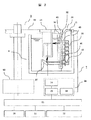
図1は、本発明の実施形態に係る攪拌機構を適用した自動分析装置の概略構成を示す斜視図であり、図2は、図1に示す自動分析装置に適用した攪拌機構周辺の断面図である。
【0018】
図1に示す自動分析装置は、主として、サンプルディスク1と、試薬ディスク2と、反応ディスク3と、反応槽4と、サンプリング機構5と、ピペッティング機構6と、攪拌機構7と、測光機構8と、洗浄機構9と、表示部10と、入力部11と、記憶部12と、制御部13とを備える。
【0019】
図1において、サンプルディスク1には、採取したサンプルが入れられた複数の試料容器16が、円形ディスク17の円周上に固定されて配置されている。そして、円形ディスク17は、図示しないモータや回転軸等から構成される駆動機構により、周方向回転し、所定の位置で停止することができる。
【0020】
また、図1において、試薬ディスク2には、サンプルと混合して反応させるための試薬が入れられた複数の試薬ボトル18が、円形ディスク19の円周上に固定されて配置されており、これらの試薬ボトル18の周囲は、温度制御された保冷庫20になっている。
【0021】
また、円形ディスク19は、図示しないモータや回転軸等から構成される駆動機構により、位置決め可能に周方向回転する。
【0022】
また、図1において、反応ディスク3には、サンプルおよび試薬を入れるための反応容器21を保持した反応容器ホルダ22が複数取り付けられており、駆動機構23により、周方向回転と停止とを一定サイクルで繰り返して、反応容器21を間欠移送する。
【0023】
また、図1において、反応槽4は、反応容器21の移動軌跡に沿って設置され、サンプルと試薬との化学反応を促進するために、例えば、温度制御された恒温水により、反応容器21内の反応液を一定温度に制御する恒温槽である。なお、この反応容器21は反応槽4内を移動する。
【0024】
また、図1において、サンプリング機構5は、プローブ24と、支承軸25に取り付けられたアーム26と、支承軸25を回転中心にサンプルディスク1と反応ディスク3との間を往復可能にする駆動機構とを備えている。
【0025】
そして、サンプリング機構5は、予め定められたシーケンスに従って、サンプルディスク1の回転と共に定位置に移送されてくる試料容器16内のサンプルを、反応容器21に供給する。
【0026】
上述したサンプリング機構5と同様に、ピペッティング機構6は、プローブ27と、支承軸28に取り付けられたアーム29と、支承軸28を回転中心に試薬ディスク2と反応ディスク3との間を往復可能にする駆動機構とを備えている。
【0027】
そして、ピペッティング機構6は、予め定められたシーケンスに従って、試薬ディスク2の回転と共に定位置に移送されてくる試薬ボトル18内の試薬を、反応容器21内に供給する。
【0028】
なお、試料容器16及び試薬ボトル18の各々には、異なる種類のサンプル及び試薬が入れられており、必要量が反応容器21に供給される。
【0029】
また、図1において、本発明に係る攪拌機構7は、その位置(攪拌位置)に移送されてきた反応容器21の側面と底面から音波を照射することで、反応容器21内のサンプルおよび試薬を撹拌して混合する非接触攪拌機構である。
【0030】
本実施形態に係る攪拌機構7は、図2に示すように、音波照射部35と音源駆動部36とから構成されている。
【0031】
音波照射部35は、音源となる圧電素子30を具備する。この圧電素子30は、電極32を複数個有し、音源駆動部36によって所定の印加電圧と周波数で加振され、加振される電極32によって音波の照射位置を変えることが可能な構成となっている。
【0032】
また、音波照射部35は図2の如く、圧電素子30の他、圧電素子30の電極数と同数の接点を有し、印加電圧を圧電素子30の各電極32に伝達する配線をパターニングした柔軟性を持つフレキシブル基板31と、各電極32とフレキシブル基板31の接点との導通をとる電極数と同数の金属球40と、金属球40を介して各電極32とフレキシブル基板31の接点とをそれぞれ独立に導通させるためにフレキシブル基板31を押し付けるバネ41と、金属球40を保持しバネ41の押し付け方向の微動を確保した保持部材42と、圧電素子30の縁沿いに設けられたゴム材からなるパッキン43と、圧電素子30から発せられる音波の一部を反射する反射板37と、これらを保持し防水構造を成す筐体38より構成される。なお、圧電素子上の電極は、正面から見ると図3のように構成されている。
【0033】
また、音源駆動部36は、電源14と、圧電素子30に印加する電圧波形を生成する駆動回路部15と、電圧を印加する電極32を選択するリレー回路39とから構成される。
【0034】
また、図2に示すように攪拌機構7は、反応槽4の恒温水に浸され、着脱可能に取り付けられている。
【0035】
図2において、サンプルおよび試薬が注入された反応容器21は、反応容器ホルダ22によって反応ディスク3に固定され、反応ディスク3の周方向回転に従って、恒温水を入れた反応槽4に浸漬された状態で移動する。
【0036】
そして、反応容器21が攪拌位置に移送されて停止すると、圧電素子30が音源駆動部36によって所定の印加電圧と周波数で加振される。このとき印加電圧は、制御部13からの指示に従い、リレー回路39で選択した電極32に供給され、電極位置に対応した位置が加振される。圧電素子30が加振されることによって発生された振動は、反応槽4の恒温水内を音波として伝播し、反応容器21の側面及び反射板37で反射されることにより反応容器21の底面に到達する。
【0037】
これら音波は、反応容器21の壁面を通過して、内部の被撹拌物であるサンプルおよび試薬に作用し、旋回流を引き起こす。この旋回流によって、サンプルの移動が促進され、サンプルおよび試薬の撹拌が行われることとなる。
【0038】
図1に戻って、測光機構8は、図示していないが、光源と、光度計と、レンズと、測光信号処理部とを備えている。この測光機構8は、反応容器21内の反応液の吸光度を測定するなど、サンプルの物性を光で測定する。
【0039】
また、洗浄機構9は、複数のノズル33と、その上下駆動機構34とを備えており、反応容器21内の反応液を吸引し、洗浄液を吐き出し、その位置(洗浄位置)に移送されてきた反応容器21を洗浄する。
【0040】
また、図1において、表示部10は、分析項目や分析結果等の各種画面表示を行う。また、入力部11は、分析項目等の各種情報の入力を行う。また、記憶部12は、各機構を制御するための予め定めたシーケンス(プログラム)および分析項目等の各種情報を記憶している。
【0041】
本発明の実施形態に係る攪拌機構7を適用した自動分析装置は、上記に記載のほかに、シリンジやポンプ等を構成要素として持ち、それらも含め、全て、記憶部12に記憶されているシーケンスに従って、制御部13により制御される。
【0042】
続いて自動分析装置の分析動作について、以下に説明する。
【0043】
まず、洗浄機構9により洗浄された反応容器21が、反応ディスク3の駆動によって試料注入位置に移送されてくると、サンプルディスク1が回転し、サンプルが入った試料容器21をサンプリング位置に移送する。試薬ディスク2も、同様に、所望の試薬ボトル18をピペッティング位置へ移送する。
【0044】
続いて、サンプリング機構5が動作し、プローブ24を用いて、サンプリング位置に移送されてきた試料容器16から、試料注入位置に移送されてきた反応容器21へサンプルを注入する。
【0045】
サンプルが注入された反応容器21は、試薬注入位置に移送され、ピペッティング機構6の動作により、試薬ディスク2上のピペッティング位置に移送されてきた試薬ボトル18から、試薬注入位置に移送されてきた反応容器21へ試薬が注入される。
【0046】
その後、反応容器21は、攪拌位置に移送され、攪拌機構7により、サンプルおよび試薬の攪拌が行われる。
【0047】
攪拌が完了した反応液は、反応容器21が光源と光度計との間を通過する際に、測光機構8により吸光度が測定される。この測定は、数サイクル間行われ、測定が終了した反応容器21は、洗浄機構9により洗浄される。
【0048】
このような一連の動作が、各反応容器21に対して実行され、本発明の実施形態に係る攪拌機構7を適用した自動分析装置による分析が行われる。
【0049】
さて、本実施形態に係る攪拌機構7を採用するにあたり、特徴となる点について説明する。
【0050】
本実施形態に係る攪拌機構7は、防水構造とした音波照射部35を独立させて反応槽4へ取り付けているため、反応容器21の停止位置に対する位置調整を可能とする。本実施例の自動分析装置では、攪拌位置を1箇所としているが、2箇所以上の攪拌位置を設定している自動分析装置では、複数箇所の攪拌位置における反応容器の停止位置が製作誤差や組立て誤差等により異なる可能性があるため、より有効である。また、反射板37を筐体38に一体化していることにより、反応容器21の側面及び底面への音波照射位置を同時に調整することが可能となる。
【0051】
また、本実施形態に係る攪拌機構7は、反応槽4の上面からの搭載を可能とすることで、反応槽4の壁面に攪拌機構取付け用の穴を設ける必要がないうえに、反応槽4への着脱を容易にするため、反応槽4や攪拌機構7の洗浄といったメンテナンス作業の効率化を図れる。
【0052】
また、本実施形態に係る攪拌機構7は、金属球40やフレキシブル基板31の採用による配線数の削減や構造の単純化などにより小型化が図られているため、測光位置周辺を除き反応槽4内のほとんどの位置に設置可能となり、自動分析装置のレイアウト設計の自由度を大きく広げることができると共に、装置の小型化を可能にする。また、構造の単純化は、製造効率向上にも寄与する。
【0053】
なお、本実施形態において、攪拌機構7の音波照射部35におけるフレキシブル基板31の押し付けにコイルバネを用いているが、一体成型された板バネを用いてさらに部品点数を削減することも可能である。また、電極32への電圧供給は、本実施形態に限らず各電極に独立に電圧供給を可能にする配線接続手段であればよい。
【0054】
なお、本実施形態において、反応槽4は恒温水により恒温槽を構成しているが、本実施例に係る攪拌機構7は音波照射部35から発せられる音波の伝播を著しく損なわない媒体であれば恒温水に限らず使用可能である。
【0055】
また、本実施形態に係る攪拌機構7は、自動分析装置の攪拌機構に限らず、水のような音波を伝播する媒体中で容器内の被攪拌物を混合する形態のものに応用可能である。
【0056】
【発明の効果】
以上説明したように本発明によれば、被攪拌物に対する音源の位置調整、及び取付け対象への着脱を容易にし、メンテナンス作業の効率化を図れる。また、レイアウトの自由度を広げると共に、装置の小型化を可能にする攪拌機構を提供できる。
【図面の簡単な説明】
【図1】本発明の実施形態に係る攪拌機構を適用した自動分析装置の構成を示す斜視図。
【図2】実施例1に係る攪拌機構周辺における縦断面図。
【図3】実施例1に係る攪拌機構の圧電素子電極構造を示す図。
【符号の説明】
1…サンプルディスク、2…試薬ディスク、3…反応ディスク、4…反応槽、5…サンプリング機構、6…ピペッティング機構、7…攪拌機構、8…測光機構、9…洗浄機構、10…表示部、11…入力部、12…記憶部、13…制御部、14…電源、15…駆動回路部、16…試料容器、17…円形ディスク、18…試薬ボトル、19…円形ディスク、20…保冷庫、21…反応容器、22…反応容器ホルダ、23…駆動機構、24,27…プローブ、25,28…支承軸、26,29…アーム、30…圧電素子、31…フレキシブル基板、32…電極、33…ノズル、34…上下駆動機構、35…音波照射部、36…音源駆動部、37…反射板、38…筐体、39…リレー回路、40…金属球、41…バネ、42…保持部材、43…パッキン。[0001]
BACKGROUND OF THE INVENTION
The present invention relates to a fluid stirring device using ultrasonic waves, and more particularly to a stirring mechanism suitable for mixing reagents and reaction solutions injected into a container in the fields of biochemistry and immunity.
[0002]
[Prior art]
The stirring mechanism that mixes the objects to be stirred by sonic irradiation can perform efficient mixing without causing carry-over between the objects to be stirred as compared with the conventional stirring by rotating the spatula.
[0003]
As this kind of agitation mechanism, for example, an invention disclosed in Japanese Patent Application Laid-Open No. 2000-146986 is known. This invention irradiates sound waves from a sound source attached to a reaction vessel to a reaction vessel in a state in which a reaction vessel in which an object to be stirred is poured into a reaction vessel filled with constant temperature water, and mixes the object to be stirred. Is.
[0004]
[Problems to be solved by the invention]
Since the stirring mechanism described in the above publication is directly installed in the reaction vessel, it restricts the position of sound wave irradiation to the object to be stirred in the reaction vessel, and it may be difficult to deal with manufacturing errors and assembly errors. There is sex.
[0005]
Further, in maintenance work such as washing of the reaction tank and the stirring mechanism, it is necessary to remove the stirring mechanism, and it is necessary to take measures against the discharge of constant temperature water and leakage by removing the stirring mechanism, which may hinder rapid work.
[0006]
In the biochemistry and immunity fields, it is required to reduce the amount of reagents and specimens and reduce the size of testing equipment. As a result, the amount of agitated materials mixed and the agitation mounted on miniaturized testing equipment are reduced. The mechanism is similarly required to be downsized. In particular, in an automatic analyzer for biochemistry or immunoassay, the reaction tank is a major factor that determines the size of the apparatus, and therefore there is a demand for downsizing not only the reaction tank but also the mechanism around the reaction tank.
[0007]
An object of the present invention is to improve attachment and detachment and positioning of a stirring mechanism and improve maintainability in a stirring mechanism using ultrasonic waves.
[0008]
[Means for Solving the Problems]
The configuration of the present invention for achieving the above object is as follows.
[0009]
(1) An ultrasonic wave generating element that generates ultrasonic waves, a drive circuit that supplies electric power to the ultrasonic wave generating elements and generates ultrasonic waves in the ultrasonic wave generating elements, and irradiates ultrasonic waves generated from the ultrasonic wave generating elements An ultrasonic container comprising: a reaction container that contains an object to be stirred that is a target object; and a container that contains an ultrasonic transmission medium for transmitting ultrasonic waves between the reaction container and the ultrasonic wave generating element. A stirring device, wherein the ultrasonic wave generating element having a plurality of sets of electrodes includes an ultrasonic wave irradiation unit sealed in a waterproof structure, and at least a part of the ultrasonic wave irradiation unit is the ultrasonic wave An ultrasonic stirring device provided to be immersed in a transmission medium.
[0010]
(2) In the ultrasonic agitator according to (1), the ultrasonic wave irradiation unit includes a wiring connection unit that enables power supply to each of the plurality of sets of ultrasonic wave generating element electrodes independently. .
[0011]
(3) In the ultrasonic agitating device according to (2), the wiring connecting means includes a flexible substrate having flexibility by patterning a wiring having the same number of contacts as the number of electrodes of the ultrasonic generating element, each electrode, A metal sphere that electrically connects the contact of the flexible board, a spring that presses each contact of the flexible board to each electrode together with the metal sphere, and a fine movement in the pressing direction of the spring holding the metal sphere. An ultrasonic agitation device comprising a secured holding member.
[0012]
(4) In the ultrasonic stirring device according to any one of (1) to (3), an ultrasonic wave provided with means capable of arbitrarily changing which of the plurality of sets of ultrasonic wave generating element electrodes is supplied with power. Stirring device.
[0013]
(5) In the ultrasonic agitator according to (4), the ultrasonic agitator provided with control means for determining which of the plurality of sets of ultrasonic generating element electrodes is supplied with power according to the amount of the object to be agitated. .
[0014]
(6) The ultrasonic stirring apparatus according to (1), wherein the ultrasonic irradiation unit is integrated with a reflector that reflects at least a part of the irradiated sound wave.
[0015]
(7) A reagent installing unit for mounting a reagent container for storing a reagent, a sample installing unit for mounting a sample container for storing a sample, and a reaction unit for mounting a reaction container for mixing and reacting the reagent and the sample A measuring unit for measuring the reaction between the reagent and the sample, a reagent dispensing device for dispensing the reagent from the reagent container to the reaction container, and a sample dispensing device for dispensing the sample from the sample container to the reaction container In the automatic analyzer comprising: the automatic analyzer, wherein the stirring device for stirring the mixture of the reagent and the sample in the reaction vessel is the ultrasonic stirring device according to any one of (1) to (6) .
[0016]
DETAILED DESCRIPTION OF THE INVENTION
Embodiments of the present invention will be described below with reference to the drawings.
[0017]
FIG. 1 is a perspective view showing a schematic configuration of an automatic analyzer to which a stirring mechanism according to an embodiment of the present invention is applied, and FIG. 2 is a cross-sectional view around the stirring mechanism applied to the automatic analyzer shown in FIG. is there.
[0018]
The automatic analyzer shown in FIG. 1 mainly includes a
[0019]
In FIG. 1, a plurality of
[0020]
In FIG. 1, a plurality of
[0021]
The
[0022]
In FIG. 1, a plurality of
[0023]
Moreover, in FIG. 1, the reaction tank 4 is installed along the movement locus | trajectory of the
[0024]
In FIG. 1, the sampling mechanism 5 includes a
[0025]
The sampling mechanism 5 then supplies the sample in the
[0026]
Similar to the sampling mechanism 5 described above, the pipetting mechanism 6 can reciprocate between the
[0027]
Then, the pipetting mechanism 6 supplies the reagent in the
[0028]
Note that different types of samples and reagents are placed in each of the
[0029]
In FIG. 1, the
[0030]
As shown in FIG. 2, the
[0031]
The sound
[0032]
Further, as shown in FIG. 2, the sound
[0033]
The sound
[0034]
Moreover, as shown in FIG. 2, the
[0035]
In FIG. 2, a
[0036]
When the
[0037]
These sound waves pass through the wall surface of the
[0038]
Returning to FIG. 1, the photometric mechanism 8 includes a light source, a photometer, a lens, and a photometric signal processing unit (not shown). The photometric mechanism 8 measures the physical properties of the sample with light, such as measuring the absorbance of the reaction solution in the
[0039]
The cleaning mechanism 9 includes a plurality of
[0040]
In FIG. 1, the
[0041]
The automatic analyzer to which the
[0042]
Next, the analysis operation of the automatic analyzer will be described below.
[0043]
First, when the
[0044]
Subsequently, the sampling mechanism 5 operates, and the sample is injected from the
[0045]
The
[0046]
Thereafter, the
[0047]
When the
[0048]
Such a series of operations is executed for each
[0049]
Now, points that are characteristic in adopting the
[0050]
The
[0051]
Further, the
[0052]
In addition, since the
[0053]
In this embodiment, the coil spring is used to press the
[0054]
In the present embodiment, the reaction tank 4 constitutes a thermostatic tank with constant temperature water, but the
[0055]
Further, the
[0056]
【The invention's effect】
As described above, according to the present invention, the position adjustment of the sound source with respect to the object to be stirred and the attachment / detachment to / from the attachment target are facilitated, and the efficiency of the maintenance work can be improved. In addition, it is possible to provide an agitation mechanism that increases the degree of freedom in layout and enables downsizing of the apparatus.
[Brief description of the drawings]
FIG. 1 is a perspective view showing a configuration of an automatic analyzer to which a stirring mechanism according to an embodiment of the present invention is applied.
FIG. 2 is a longitudinal sectional view around a stirring mechanism according to a first embodiment.
3 is a diagram showing a piezoelectric element electrode structure of a stirring mechanism according to
[Explanation of symbols]
DESCRIPTION OF
Claims (3)
該超音波発生素子に電力を供給する駆動回路と、
該超音波発生素子から発生した超音波を照射する被攪拌物を収容する反応容器と、
該反応容器と前記超音波発生素子との間で超音波を伝達するための超音波伝達媒体を収容する容器と、を備えた超音波攪拌装置であって、
前記超音波発生素子が防水構造の筐体に封止された超音波照射部を備え、かつ該超音波照射部が前記超音波伝達媒体を収容する容器から着脱可能に独立させて取り付けられており、
かつ前記超音波発生素子は複数組の超音波発生素子電極を備え、該超音波発生素子の電極数と同数の接点を持つ配線をパターニングした柔軟性を有するフレキシブル基板と、各電極と前記フレキシブル基板の接点とを電気的に接続する金属球と、前記フレキシブル基板の各接点を前記金属球と共に各電極へそれぞれ独立に押し付けるバネと、前記金属球を保持し前記バネの押し付け方向の微動を確保した保持部材とから構成された配線接続手段を備えたことを特徴とする超音波攪拌装置。An ultrasonic wave generating element for generating ultrasonic waves;
A drive circuit for supplying power to the ultrasonic generator;
A reaction container for containing an object to be stirred for irradiating ultrasonic waves generated from the ultrasonic wave generating element;
An ultrasonic stirrer comprising: a container containing an ultrasonic transmission medium for transmitting ultrasonic waves between the reaction vessel and the ultrasonic wave generating element;
The ultrasonic generating element includes an ultrasonic irradiation unit sealed in a waterproof structure, and the ultrasonic irradiation unit is detachably attached to a container housing the ultrasonic transmission medium. ,
The ultrasonic generation element includes a plurality of sets of ultrasonic generation element electrodes, a flexible substrate having flexibility in patterning a wiring having the same number of contacts as the number of electrodes of the ultrasonic generation element, each electrode, and the flexible substrate A metal sphere that electrically connects the contact of each of the contacts, a spring that presses each contact of the flexible substrate independently to each electrode together with the metal sphere, and the metal sphere is held to ensure fine movement in the pressing direction of the spring. An ultrasonic agitating device comprising a wiring connecting means comprising a holding member .
前記超音波照射部は照射される音波の少なくとも一部を反射する反射板を備えたことを特徴とする超音波攪拌装置。The ultrasonic stirring apparatus according to claim 1 ,
The ultrasonic stirring device, wherein the ultrasonic irradiation unit includes a reflecting plate that reflects at least a part of the irradiated sound wave.
該反応容器での試薬と試料の反応を測定する測定部と、
を備えた自動分析装置において、
前記反応容器中の試薬と試料の混合物を攪拌するための攪拌装置が、請求項1または2に記載の超音波攪拌装置であることを特徴とする自動分析装置。A reaction section on which a reaction vessel for mixing and reacting a reagent and a sample is placed;
A measuring unit for measuring the reaction between the reagent and the sample in the reaction vessel;
In an automatic analyzer equipped with
The automatic analyzer, wherein the stirring device for stirring the mixture of the reagent and the sample in the reaction vessel is the ultrasonic stirring device according to claim 1 or 2 .
Priority Applications (1)
| Application Number | Priority Date | Filing Date | Title |
|---|---|---|---|
| JP2001218926A JP3832282B2 (en) | 2001-07-19 | 2001-07-19 | Ultrasonic stirring device and automatic analyzer using the same |
Applications Claiming Priority (1)
| Application Number | Priority Date | Filing Date | Title |
|---|---|---|---|
| JP2001218926A JP3832282B2 (en) | 2001-07-19 | 2001-07-19 | Ultrasonic stirring device and automatic analyzer using the same |
Publications (2)
| Publication Number | Publication Date |
|---|---|
| JP2003035715A JP2003035715A (en) | 2003-02-07 |
| JP3832282B2 true JP3832282B2 (en) | 2006-10-11 |
Family
ID=19053023
Family Applications (1)
| Application Number | Title | Priority Date | Filing Date |
|---|---|---|---|
| JP2001218926A Expired - Lifetime JP3832282B2 (en) | 2001-07-19 | 2001-07-19 | Ultrasonic stirring device and automatic analyzer using the same |
Country Status (1)
| Country | Link |
|---|---|
| JP (1) | JP3832282B2 (en) |
Families Citing this family (5)
| Publication number | Priority date | Publication date | Assignee | Title |
|---|---|---|---|---|
| JP3914838B2 (en) * | 2002-07-10 | 2007-05-16 | 株式会社日立ハイテクノロジーズ | Automatic analyzer |
| JP4887174B2 (en) | 2007-02-19 | 2012-02-29 | 株式会社日立ハイテクノロジーズ | Automatic analyzer |
| JP2009270941A (en) | 2008-05-08 | 2009-11-19 | Hitachi High-Technologies Corp | Automatic analysis apparatus |
| JP5668021B2 (en) * | 2012-05-24 | 2015-02-12 | 株式会社日立ハイテクノロジーズ | Automatic analyzer |
| WO2015079829A1 (en) | 2013-11-26 | 2015-06-04 | 株式会社 日立ハイテクノロジーズ | Automatic analyzer |
-
2001
- 2001-07-19 JP JP2001218926A patent/JP3832282B2/en not_active Expired - Lifetime
Also Published As
| Publication number | Publication date |
|---|---|
| JP2003035715A (en) | 2003-02-07 |
Similar Documents
| Publication | Publication Date | Title |
|---|---|---|
| US8430555B2 (en) | Agitation apparatus, vessel, and analysis apparatus including agitation apparatus | |
| EP1128185B1 (en) | Mixing device for automatic analyzer | |
| US20080074945A1 (en) | Agitation Vessel | |
| JP3168886B2 (en) | Chemical analyzer | |
| WO2009136612A1 (en) | Automated analyzer | |
| JP4887174B2 (en) | Automatic analyzer | |
| JP3832282B2 (en) | Ultrasonic stirring device and automatic analyzer using the same | |
| JP2007248298A (en) | Agitator and analyzer | |
| JP3641992B2 (en) | Chemical analyzer | |
| JP3642713B2 (en) | Automatic analyzer | |
| JP3607557B2 (en) | Automatic analyzer | |
| JP2007057318A (en) | Analyzer, feeder, stirring device and stirring method | |
| JP3914838B2 (en) | Automatic analyzer | |
| WO2001077691A1 (en) | Chemical analyzer | |
| JP2019124608A (en) | Chemical analyzer and sound wave stirrer used in chemical analyzer | |
| JP3121829U (en) | Automatic analyzer | |
| JP4377318B2 (en) | Automatic analyzer | |
| EP2127749B1 (en) | Method of manufacturing a reaction cuvette for use in an automatic analyzer and apparatus for manufacturing a reaction cuvette | |
| JP5919364B2 (en) | Automatic analyzer | |
| JP5668021B2 (en) | Automatic analyzer | |
| JP2022126439A (en) | Autoanalyzer | |
| WO2007099684A1 (en) | Stirrer and analyzer | |
| JP3829145B2 (en) | Automatic analyzer | |
| JP2023014644A (en) | automatic analyzer | |
| JP2002071697A (en) | Automatic analyzer |
Legal Events
| Date | Code | Title | Description |
|---|---|---|---|
| A977 | Report on retrieval |
Free format text: JAPANESE INTERMEDIATE CODE: A971007 Effective date: 20050111 |
|
| A131 | Notification of reasons for refusal |
Free format text: JAPANESE INTERMEDIATE CODE: A131 Effective date: 20050125 |
|
| A521 | Written amendment |
Free format text: JAPANESE INTERMEDIATE CODE: A523 Effective date: 20050310 |
|
| A131 | Notification of reasons for refusal |
Free format text: JAPANESE INTERMEDIATE CODE: A131 Effective date: 20060404 |
|
| RD01 | Notification of change of attorney |
Free format text: JAPANESE INTERMEDIATE CODE: A7421 Effective date: 20060418 |
|
| A521 | Written amendment |
Free format text: JAPANESE INTERMEDIATE CODE: A523 Effective date: 20060525 |
|
| TRDD | Decision of grant or rejection written | ||
| A01 | Written decision to grant a patent or to grant a registration (utility model) |
Free format text: JAPANESE INTERMEDIATE CODE: A01 Effective date: 20060627 |
|
| A61 | First payment of annual fees (during grant procedure) |
Free format text: JAPANESE INTERMEDIATE CODE: A61 Effective date: 20060710 |
|
| R151 | Written notification of patent or utility model registration |
Ref document number: 3832282 Country of ref document: JP Free format text: JAPANESE INTERMEDIATE CODE: R151 |
|
| FPAY | Renewal fee payment (event date is renewal date of database) |
Free format text: PAYMENT UNTIL: 20090728 Year of fee payment: 3 |
|
| FPAY | Renewal fee payment (event date is renewal date of database) |
Free format text: PAYMENT UNTIL: 20100728 Year of fee payment: 4 |
|
| FPAY | Renewal fee payment (event date is renewal date of database) |
Free format text: PAYMENT UNTIL: 20100728 Year of fee payment: 4 |
|
| FPAY | Renewal fee payment (event date is renewal date of database) |
Free format text: PAYMENT UNTIL: 20110728 Year of fee payment: 5 |
|
| FPAY | Renewal fee payment (event date is renewal date of database) |
Free format text: PAYMENT UNTIL: 20110728 Year of fee payment: 5 |
|
| FPAY | Renewal fee payment (event date is renewal date of database) |
Free format text: PAYMENT UNTIL: 20120728 Year of fee payment: 6 |
|
| FPAY | Renewal fee payment (event date is renewal date of database) |
Free format text: PAYMENT UNTIL: 20130728 Year of fee payment: 7 |
|
| EXPY | Cancellation because of completion of term |