JP3832172B2 - Liquid crystal device and electronic apparatus using the same - Google Patents
Liquid crystal device and electronic apparatus using the same Download PDFInfo
- Publication number
- JP3832172B2 JP3832172B2 JP2000025717A JP2000025717A JP3832172B2 JP 3832172 B2 JP3832172 B2 JP 3832172B2 JP 2000025717 A JP2000025717 A JP 2000025717A JP 2000025717 A JP2000025717 A JP 2000025717A JP 3832172 B2 JP3832172 B2 JP 3832172B2
- Authority
- JP
- Japan
- Prior art keywords
- liquid crystal
- layer
- crystal device
- display
- substrate
- Prior art date
- Legal status (The legal status is an assumption and is not a legal conclusion. Google has not performed a legal analysis and makes no representation as to the accuracy of the status listed.)
- Expired - Fee Related
Links
Images


Landscapes
- Liquid Crystal (AREA)
Description
【0001】
【発明の属する技術分野】
本発明は、液晶装置及びこれを用いた電子機器に関するものであり、より詳しくは、反射型表示と透過型表示の機能を兼ね備えた液晶装置に関するものである。
【0002】
【背景技術】
液晶表示装置は、互いに対向する一対の基板間に液晶を配して成る非発光形のディスプレイであり、液晶の配向状態に応じて液晶を通過する光を変調させて表示を行うものである。かかる液晶表示装置の表示方式としては、透過型と反射型のものが知られている。
【0003】
このうち、図12に示す透過型の表示方式は、基板220と対向基板240との対向面にそれぞれITO(Indium Tin Oxide)等の透明電極280、280を配設し、液晶260における液晶分子の配向状態を制御することで、基板220の外側に設けた光源(バックライト)400から照射された光を、液晶260で変調することによって画像表示を行うようになっている。一方、図13に示す反射型の表示方式は、例えば基板220の外側に光反射性を有する反射金属膜300を設け、対向基板240側から入射した外部光420を、液晶260を介して当該金属膜300で反射させて入射側へ戻った光を、液晶260で変調することにより画像を表示する。そして、上記した反射型の場合、透過型のようなバックライト等の光源を設けなくとも、蛍光灯や自然光等の外部光により表示を行うことができ、消費電力の点で有利であるので、携帯型表示機器等への使用が広く行われている。
【0004】
ところが、反射型の液晶表示装置においては、外部光がほとんどない場合に表示が困難になるという問題がある。このようなことから、近年、反射型と透過型を兼ね備えた表示方式も提案されており、外部光に応じて反射型と透過型のいずれかの表示方式に切り替えることにより、消費電力を低減しつつ、周囲が暗い場合でも明瞭な表示を行うことができるようになっている。
【0005】
かかる反射・透過型の液晶表示装置としては、特開平7−294896号公報に記載の技術が知られている。この液晶表示装置は、図14に示すように各基板220A、240Aの対向面にそれぞれ透明電極280A、280Bを設け、さらに、基板220Aの外側に半透過反射板620とバックライト500を配設することにより、反射・透過の兼用表示が可能となっている。また、対向基板240A側の透明電極280Bはマトリクス状の画素電極となっていて、各画素電極の間には拡散反射膜600が配設されている。
【0006】
そして、透過表示時には、バックライト500からの光は、上下の電極280B、280Aで挟まれた画像表示領域D10から透過光P10として出射され、一方で領域D20における透過光P20は拡散反射膜600で反射され、外部へ漏れないようになっている。つまり、透過表示時には拡散反射膜600がブラックマスクとなるので、高コントラストの画像を得ることができる。
また、反射表示時には、外部光420は表示領域D10に入射し、半透過反射板620で反射されて反射光R10として出射される。さらに、領域D20に入射された光も反射膜600で反射され、反射光R20として出射される。つまり、反射表示時には、拡散反射膜600からの反射光により光量が増えるので、反射表示を明るくすることができる。
【0007】
【発明が解決しようとする課題】
図14に記載したように基板の外側に半透過反射板を設ける外部反射型の液晶装置では、半透過反射板と、透過表示時の遮光層として機能する拡散反射層がそれぞれ別々の構成となっている。さらに、図14に記載した拡散反射層600は、反射表示時の明るさを向上させることができるものの、反射表示時にはブラックマスクとなる部分がないので、そのため反射表示時のコントラストの低下は避けられない。
【0008】
本発明は、上述した課題を解決するためのもので、まず第1に、半透過反射型の液晶装置であって、反射層を、液晶層を挟持する一対の基板のうち、一方の基板の他方の基板と対向する面(液晶層側の面)に配設することにより、透過表示用に別途ブラックマスクを設けることなく、透過表示時にはこの反射層がブラックマスクの機能を兼ねるようにし、透過表示時のコントラスト向上を図ることのできる半透過反射型を提供することを第1の目的とする。
【0009】
さらに、反射表示時も明瞭な表示を行うことができる液晶装置を提供することを第2の目的とする。
【0010】
そして、本発明の液晶装置を用いた電子機器の提供を目的とする。
【0011】
【課題を解決するための手段】
上記した目的を達成するために、本発明の液晶装置は、一対の基板間に液晶を挟持し、各基板の対向面にはそれぞれ電極が形成され、一方の前記基板の前記対向面には、前記電極とは別の層からなり、かつ、金属膜から成る反射層が配設されている半透過反射型の液晶装置であって、前記電極同士が対向してなる複数の画素を有し、前記反射層は前記画素間に設けられるとともに、前記反射層の周縁部が前記画素の周縁部より内側に設けられ、
前記反射層の上に遮光層が形成されることを特徴とする。
【0012】
このような構成によれば、半透過反射の液晶装置において、反射層が透過表示時の遮光層として機能させることができるので、透過表示時用に別途遮光層を設けることなく、透過表示時に高コントラストを達成することができる。
【0013】
前記遮光層の周縁部は、前記画素の周縁部より外側に位置するとともに互いに重ならないように配置されることを特徴とする。
また、本発明においては、前記一方の基板の外側に光源が配設されていることが好ましい。
【0014】
そして、前記電極の一方はマトリクス状に配設された複数の画素電極から成り、かつ、前記窓の周縁部は各画素電極の周縁部より内側に位置していることが好ましい。
【0015】
さらに、前記各画素電極の周縁部より外側における前記一方の基板には、遮光層が形成されていることが好ましい。
【0016】
前記窓は、前記各画素電極に対してそれぞれ1つ以上設けられていることが好ましい。
【0017】
本発明においては、前記窓の総面積は、全画素面積に対して10〜60%の割合になっていることが好ましい。
【0018】
また、前記反射層の反射率は85%以上であることが好ましい。
【0019】
そして、前記反射層はアルミニウム、銀又はこれらの合金から成ることが好ましい。
【0020】
さらに、前記一方の基板における電極と反射層の間には、カラーフィルタ層が形成されていることが好ましい。
【0021】
本発明の電子機器は、前記液晶表示装置を備えたことを特徴とする。
【0022】
【発明の実施の形態】
(第1の実施形態)
以下、本発明の第1の実施形態に係る液晶装置について、図1、図2に基づいて説明する。
【0023】
なお、本発明における「液晶装置」とは、少なくとも一対の基板間に液晶を有し、各基板の対向面にはそれぞれ電極を備え、さらに後述する反射層を備えたものをいうが、電極の種類、形状等については制限はなく、液晶表示の方式(アクティブマトリクス型、あるいはパッシブマトリクス型等)に応じて適宜電極を配設すればよい。又、アクティブマトリクス型の液晶装置の場合、画素制御用の素子についても制限はなく、液晶装置の動作方式(TFT(Thin Film Transistor)方式、TFD(Thin Film Diode)方式等)に応じて適宜素子を配設すればよい。その他のカラーフィルタ等についても、必要に応じて基板上に配設する。
【0024】
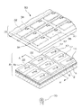
図1に示すように、本発明の液晶装置50は、アクティブマトリクス型のTFD(Thin Film Diode)液晶装置をなし、一方の基板8と他方の基板38が所定の間隔で対向配置され、各基板8、38は、その対向面間に図示しない液晶層を介在させている。ここで、他方の基板38は素子基板となっていて、ガラス等から成る透明な基板30の下面(対向面)にマトリクス状に例えばITO(Indium Tin Oxide)等の透明電極から成る複数の画素電極32、及び該画素電極32を制御するためのTFD36が設けられている。各画素電極32は、略矩形状に形成され、そのうち一の隅部のTFD素子36が配設される部分は切欠部となっている。TFD36は、各列あるいは各行毎、データ線あるいは走査線となる配線34に接続される。そして、信号線と、基板8側に設けられる対向電極22(配線34がデータ線の場合には走査電極、配線34が走査線の場合にはデータ電極となる。)とに印加された信号に基づいて、各画素に対応する液晶の配向状態を表示状態、非表示状態またはその中間状態に切り替えて表示動作の制御を行うことができるようになっている。
【0025】
また、一方の基板8はカラーフィルタ基板になっていて、ガラス等から成る透明な基板2上に金属膜から成る反射層4が、シール材内部の画素領域ほぼ全面にわたって形成されている。そして、反射層4の上には、RGBそれぞれの着色層14、12、10を有するカラーフィルタ層、及び、ITOなどの透明な材料から成り、基板38側の信号電極の延在する方向と直交する方向に延在し、走査線あるいはデータ線となるストライプ状の対向電極22が形成されている。各画素電極32と各対向電極が交差する部分が、各画素(ドット)を構成している。
【0026】
また、 各着色層10、12、14は、他方の基板38の画素電極32と対向する位置、すなわち、各画素に対応して、マトリクス状に配設され、青色の着色層(図示「B」)10、緑色の着色層(図示「G」)12、赤色の着色層(図示「R」)14から構成されている。
【0027】
さらに、各着色層10、12、14の中心付近、すなわち、各画素の中心付近において、反射層4は矩形状の小さな窓4aを有している。一方の基板8の外側には、光源(バックライト)70が配設され、光源から放たれた光は、基板8の対向面とは反対側(外側)の面から基板8に入射し、さらに、他方の基板38側へ透過するようになっている。つまり、この液晶装置50では、各画素周縁部では反射層4による反射表示を行い、その中心部の窓4aの部分では透過表示を行うようになっている。
ここで、各着色層は光の3原色(R、G、B)を構成しているので、いずれかの方向において、R、G、Bが交互に配設されていることが好ましい。例えばこの実施形態ではカラーフィルタ側基板8の左から右(AからA’)へ向かってB、G、Rが交互に配設されているが、これと直角な方向にR、G、Bが交互に配設されていてもよい。また、着色層10、12、14は、各画素毎にそれぞれ離間配置され、各着色層の間(他方の基板38の画素電極32が形成されていない領域)には、反射表示時に遮光層として機能する遮光層6が形成され、各着色層10、12、14と遮光層6とからカラーフィルター層を構成している。カラーフィルタ層の上に、図示しない保護層20を形成し、該保護層の上に対向電極22を形成する。
【0028】
ここで、反射層4となる金属膜としては特に制限はないが、例えばアルミニウム、銀、あるいはこれらの合金(例えばアルミニウム−パラジウム−銅合金、銀ーパラジウム−銅合金)等の高反射率の材料を用いることができる。特に、反射層4の反射率が85%以上、より好ましくは90%以上になっていることが好ましい。さらに、反射層4の表面に膜厚80nm程度の透明なシリコン酸化膜やシリコン窒化膜を設け、カラーフィルタ層との密着性を向上させることもできる。カラーフィルタ層の各着色層10、12、14および遮光層6は、例えば染色法や顔料分散法によって製造することができる。
【0029】
上記した液晶装置50の断面構造は、図2に示すようになっている。
【0030】
この図において、窓4aの周縁部は、各画素電極32の周縁部32aより内側、すなわち、各画素より内側に位置している。また、遮光層6は、基板2上に形成された反射層4の上に形成されることとなる。そして、遮光層6の周縁部6aは、各画素電極32の周縁部32aより若干外側に位置し、互いに重ならない状態で配置される。よって、周縁部6aと周縁部32aとの間には、対向する画素電極が存在しない状態で反射層4が形成されている(図示領域D4)。そして、カラーフィルタ層上に、例えばアクリル系樹脂から成る保護層20を介して対向電極22が形成されている。
【0031】
このように、反射層4と対向電極22とを別の層から構成することにより、反射層4の窓4aの大きさは、液晶駆動領域に関係なく設定することができる。従って、反射層4の窓4aの開口率を変化させることにより、反射表示と透過表示とで画像表示領域の大きさを変化させることができるので、反射表示に重きをおくか、あるいは、透過表示に重きをおくか、によって、開口率を自由に設定することができる。
【0032】
以下、反射表示と透過表示に分けて説明する。
【0033】
まず、反射表示は以下のようにして行われる。他方の基板38の外側から入射した外部光80は、液晶層40を経て対向電極22の下に位置する反射層4の上面で反射し、各画素に対応する液晶の配向状態により変調され、他方の基板38側に出射して画像表示される。そして、1つの画素について、正味の反射時の画像表示領域は、画素電極32と反射層4で挟まれた部分(図示領域D1)となっている。、反射層4の形成領域のうち、画素電極32と対向電極22が重ならない部分(図示領域D4+D3)は液晶が駆動しない非駆動領域となるが、遮光層6(図示領域D3)では入射光80が反射されないので、黒表示がなされて、反射時のコントラストを向上させることが可能となる。
【0034】
次に、透過表示は以下のように行われる。まず、光源(バックライト)70から放たれ、基板2を通って反射層4に到達した光70aは、窓4aからのみ透過し、窓4aに対応する部分の液晶40で変調され、他方の基板38に出射し、画像表示される。そして、1つの画素について、正味の透過時の画像表示領域は、画素電極32と窓4aで挟まれた部分(図示領域D2)となっている。これに対し、金属膜である反射層4は光をほとんど透過させないため、窓4a以外の部分では、光70aは反射層4の下面で基板2側へ反射し、他方の基板38に到達することができない。つまり、窓4a以外の部分では光漏れを生じることなく確実な黒表示がなされ、反射層4が遮光機能を有し、透過表示時のコントラストを向上させることができる。
【0035】
本実施例の半透過反射型の液晶装置によれば、透過表示時に反射層4が遮光機能を兼ねるので、透過表示用に、別途窓4a以外の部分を遮光する層を設けることなく、半透過表示の高コントラストを得ることができる。
【0036】
さらに、本実施例の半透過反射型の液晶装置では、上述したように、各基板に配設された液晶を駆動するための電極32、22の面積は反射射表示と透過表示とで一定なので、各表示毎に液晶層の駆動領域/非駆動領域が変化することはない。しかしながら、上記したように、反射層に形成された窓が反射表示時には非表示部となり、透過表示時には表示部に転化することにより、反射表示と透過表示とで画像表示領域の大きさを変化させることができる。すなわち、液晶の配向状態によるオン、オフ比を充分にとりながら、所望の窓の面積を設定することができる。
【0037】
すなわち、上記反射層は電極とは別に形成され、電極としての機能を有していないので、この反射層に形成させる窓の開口面積を自由に調整し、例えば窓の開口面積を相対的に小さくすれば、反射モードで明るい表示を行なうことができ、窓の開口面積を相対的に大きくすれば、透過モードで明るい表示を行うことができる。つまり、液晶装置の用途等に応じて、反射表示と透過表示とで画像表示領域の大きさを任意に設定することができる。ここで、反射表示と透過表示の双方を適切に行うためには、窓4aの総面積(各窓の開口面積の総和)が総画素面積に対して10〜60%の割合になっていることが好ましい。窓4aの総面積が10%未満である場合は、透過表示時の明るさが不充分になるおそれがあり、60%を超えると、反射表示時の明るさが不充分になるおそれがあるからである。
【0038】
また、反射表示時のコントラストをそれほど必要としない場合には、各画素電極32の間(周縁部より外側)に、必ずしも遮光層6を形成する必要はない。遮光層6がある場合には、遮光層を形成すると他方の基板38側からの入射光がこの部分で吸収され、漏れ光として反射されることがないので、反射表示時のコントラストをより向上させることができる。なお、上記した実施形態において、遮光層6は、基材となるフォトレジストに、光の3原色(R、G、B)をなす各色素とカーボンブラック等の黒色粒子を含有して成るが、例えば、各着色層10、12、14を遮光層の形成領域に延設させ、各着色層を重ねることにより遮光層とすることもできる。このように、各着色層を重ねて、この重ね部分で遮光層を構成する場合には、反射表示時用の遮光層形成工程を省略、すなわち、遮光層6を形成する工程を省略できる。この場合、透過表示用には反射層4が遮光の機能を有するので、透過表示用の遮光層を形成する必要もなく、また、反射表示用の遮光層を形成する必要もなくなる。すなわち、簡易なプロセスかつ簡単な構造で、反射表示時にも透過表示時にも、コントラストを向上させることができる。本発明の液晶装置は、例えば図3〜図5に示すようにして製造することができる。なお、図3〜図5は、各工程における液晶装置50の各層を、図2と同様に図1のA−A’断面に対応させて示す工程図である。なお、以下の説明で「反射層4の上に形成する」という場合、この反射層4には窓4aが含まれていてもよいこととする。
【0039】
まず、石英やガラスなどから成り、表面にアルミニウム膜(膜厚約100〜200nm)から成る反射層4が形成された基板2を用意する。基板2の他方の基板30と対向する対向面のうち、少なくとも反射層4が形成される基板表面は複数の凹凸を有する散乱面であることが好ましい。反射層4は、例えばスパッタリングによって形成することができる。そして、例えば、所定のレジストをマスクとし、反射層4の一部をエッチング除去することにより、反射層4の所定位置に窓4aを形成する。なお、基板2の表面に例えばシリコン酸化膜等から成る下地保護層を予め形成しておいてもよい。
【0040】
そして、図3(1)に示すように、窓4aを含む反射層4の表面に、青色、赤色、緑色の各顔料及びカーボンブラックを分散させた黒色のフォトレジスト(感光性樹脂)を塗布し、遮光層形成用膜106を形成する。
【0041】
次に、図3(2)に示すように、この遮光層形成用膜106上に所定のマスク180aを配設して露光を行い、未露光部のレジストをアルカリ等で除去してパターニングを行う。そして、残った膜を適宜焼成することにより、図3(3)に示す遮光層6を形成する。
【0042】
次に、図3(4)に示すように、遮光層6の上及び表出した反射層4(窓4aを含む)の上に、青色の着色層形成用膜110を形成する。膜110としては、所定のフォトレジストに青色顔料を分散させたものを用いることができる。また、以下の緑色及び赤色の着色層形成用膜は、上記した青色顔料に代えて、それぞれ緑色及び赤色の顔料をフォトレジストに分散させたものを用いればよい。
【0043】
そして、所定のマスクを用いて青色の着色層形成用膜110を露光・現像・パターニングし、図4(5)に示す青色の着色層10を形成する。次に、図4(6)に示すように、青色の着色層10の上、遮光層6の上及び表出した反射層4(窓4aを含む)の上に、緑色の着色層形成用膜112を形成し、所定のマスクを用いて露光・現像・パターニングを行い、図4(7)に示す緑色の着色層12を形成する。以下、同様にして、図4(8)に示す赤色の着色層14を形成する。
【0044】
さらに、図5(9)に示すように、各着色層10、12、14、及び遮光層6の上に、アクリル系樹脂から成る保護層20(膜厚約1〜4μm)を形成し、その上にITO(Indium Tin Oxide)から成るストライプ状の対向電極22(膜厚約100〜300nm)を形成することにより、一方の基板8が製造される。これらに加えて、一方の基板8の表面に適宜配向膜を形成してもよい。なお、上記した例では、青色の着色層、緑色の着色層、赤色の着色層の順に形成したが、各着色層の形成順序は特に制限されることはない。
【0045】
なお、一方の基板8に対向配置される他方の基板38については工程図を省略するが、概略以下のようにして製造することができる。まず、ガラス等の所定の基板30の表面に例えばタンタル膜をスパッタリングし、熱酸化させて酸化タンタルから成る下地膜を形成する。そして、その上に、タングステンを含むタンタルを成膜し、所定のパターニングを行って、タンタルによる配線34及び該配線34から直角方向に延設されてTFDを構成する片状部を形成した後、この配線34と片状部を酸化させてこれらの表面に絶縁膜を形成する。そして、該絶縁膜の上にクロム等から成る導電膜をスパッタリングにより成膜して、適宜パターニングすることにより、片状部と交差する導電膜を形成する。この片状部、絶縁膜、及び導電膜からTFD36が構成される。さらに、前記導電膜と一部重なるようにしてITOから成る画素電極32をマトリクス状に形成し、基板38を製造する。このとき、配線34が、タンタル、クロム、ITOが積層されたものとしてもよい。
【0046】
そして、各基板8、38を所定のスペーサ、シール材を介して対向配置して、圧着するとともに、シール材で囲まれたギャップに、シール開口部から液晶を注入し、最後に開口部を封止する。なお、各基板8、38の間隔は、シール材に含まれるグラスファイバ、及びシール材の内側に配置されるビーズ状スペーサによって、例えば5μm程度に規定されている。さらに、走査信号やデータ信号を供給する駆動回路を適宜各基板8、38に実装し、所定のバックライト70を装着することにより、液晶装置50とすることができる。本実施形態では、バックライトを簡略な構成で示したが、液晶パネルの大きさに応じた面状光源とすることが好ましい。
【0047】
図6では、本実施形態1による透過表示を主体とする半透過反射型液晶装置50Aを示す。一方の基板8Aにおける窓4bを遮光層6Aの周縁部に沿うように開口させ、窓の開口面積を大きくとっている。このようにすると、透過表示時の画像表示領域の割合が大きくなり、透過表示時の明瞭な画像表示を行うことができる。なお、この液晶装置50Aの場合、他方の基板38については、前記図1に示した実施形態と同じものが用いられる。
【0048】
(第2の実施形態)
上記第1の実施形態形態では、一方の基板側でなく、他方の基板側に画素電極とその制御素子が設けられた場合について説明したが、第2の実施形態として、反射層が配設される基板側に、画素電極とこれを駆動する素子が形成される場合について説明する。
【0049】
図7では、TFT駆動型の液晶装置50Bを説明する。
【0050】
この図において、TFT型の液晶装置50Bは、一方の基板8B及び他方の基板38Bを備え、各基板8B、38Bの間には液晶40が介在されている。そして、他方の基板38Bの表面(下面)の全体には、ITOから成る対向電極22Bが設けられている。
【0051】
一方、素子基板である一方の基板8Bは以下のように構成されている。まず、基板2の表面には、後述する画素電極32Bに対応する位置にマトリクス状に反射層4Bが複数個形成され、各反射層4Bの中央部分には矩形状の窓4dが形成されている。又、反射層4Bの縦の辺(図の紙面手前から奥の方向)に沿って走査線34Bが延設され、反射層4Bの横の辺(図の左右方向)に沿ってデータ線24が延設されている。さらに、反射層4Bに隣接して各画素電極32Bを制御するTFT36Bが配設されている。TFT36Bは、その一端部が走査線34Bに接続され、他端部はスルーホール33を介して画素電極32Bに接続され、データ線24から延びる片状部がTFT36Bの上に形成されている。そして、データ線24に供給されるデータ信号によりTFT36Bのオン・オフ動作が行われ、走査線34Bから画素電極32Bへ供給される画像信号が制御されている。
【0052】
そして、反射層4Bの上には各着色層10B、12B、14Bからなるカラーフィルタ層が形成され、基板2における反射層4B以外の部分(TFT36Bの上を含む)には、各着色層10B、12B、14Bを重ねて形成され、遮光層6Bが形成されている。さらに、各着色層10B、12B、14B、及び遮光層6Bの上には保護層20Bが形成され、その上には、各反射層4Bに対応した位置にITOから成る画素電極32Bがマトリクス状に形成されている。
【0053】
本実施形態でも第1の実施形態で述べたように、透過表示時には、反射層が遮光としての機能を有するので、透過表示用に遮光層を別途設けることなく、透過表示時のコントラストの向上を図ることができる。さらに、カラーフィルタ層では、各着色層を重ねた部分で反射時用に遮光層を形成しているので、別途遮光層を設けることなく、反射表示時のコントラスト向上を図ることができる。
【0054】
(第3の実施形態)
次に第3の実施形態を図8に基づいて説明する。第3の実施形態が第1の実施形態と異なる点は、カラーフィルター層が遮光層6を有していない点、画素以外の部分(画素電極が存在しない部分に対応する一方の基板8cの位置)で、反射層が形成されない点である。その他の点では、第1の実施形態と同様であるので、液晶装置、液晶装置液晶装置自体及び他方の基板38についての説明を省略する。
【0055】
図8において、液晶装置50Cを構成する一方の基板8Cは、以下のようになっている。まず、基板2上には、他方の基板38の画素電極32に対応する位置にマトリクス状に反射層4Cが形成され、各反射層4Cの中央部分には矩形状の窓4eが形成されている。そして、各反射層4Cの上に各カラーフィルタ層10C、12C、14Cがそれぞれ形成され、各カラーフィルタ層の周縁部は反射層4Cの端縁部を覆っている。そして、各カラーフィルタ層及び基板2の上に保護層20Cが形成され、その上に短冊状のデータ線(電極)22Cが形成されている。ここで、この液晶装置8Cには遮光層が形成されていないが、各反射層4Cの間では入射光が反射することがないので、この部分は反射表示時に遮光機能を有する部分となる。すなわち、反射表示時には、各画素間の反射層開口部全体を遮光部分として機能させることができる。従って、実施形態1の液晶装置と同様に、透過表示時には、反射層を遮光機能を有する膜とすることができるとともに、反射表示時には、各画素間の反射層が形成されない部分を遮光部分として機能させるので、別途遮光層を設けることなく、透過時と反射時双方でコントラストを向上させることができる。
【0056】
[電子機器]
以下、本発明の液晶装置を備えた電子機器の具体例について説明する。
【0057】
図9は、携帯電話の一例を示した斜視図である。
【0058】
図9において、符号1000は携帯電話本体を示し、符号1001は上記の液晶装置を用いた液晶表示部を示している。
【0059】
図10は、腕時計型電子機器の一例を示した斜視図である。
【0060】
図10において、符号1100は時計本体を示し、符号1101は上記の液晶装置を用いた液晶表示部を示している。
【0061】
図11は、ワープロ、パソコンなどの携帯型情報処理装置の一例を示した斜視図である。
【0062】
図11において、符号1200は情報処理装置、符号1202はキーボードなどの入力部、符号1204は情報処理装置本体、符号1206は上記の液晶装置を用いた液晶表示部を示している。
【0063】
図9ないし図11に示す電子機器は、上記の液晶装置を用いた液晶表示部を備えたものであるので、反射と透過の兼用表示が可能であり、消費電力を低減しつつ明瞭な表示が可能な電子機器を実現することができる。
【0064】
【発明の効果】
以上説明したように、本発明では、透過表示時に反射層を遮光機能を有する膜として機能させることができるので、透過表示用のブラックマスクを別途設けることなく、透過表示時に高いコントラストを得ることができる。
【図面の簡単な説明】
【図1】 本発明の液晶装置を示す斜視図である。
【図2】 図1のA−A’線に沿う断面図である。
【図3】 液晶装置の製造プロセスを示す工程断面図である。
【図4】 図3に続く工程断面図である。
【図5】 図4に続く工程断面図である。
【図6】 本発明の液晶装置の別の例を示す斜視図である。
【図7】 本発明の液晶装置のさらに別の例を示す部分断面図である。
【図8】 本発明の液晶装置の他の例を示す部分断面図である。
【図9】 本発明の電気光学装置を備えた電子機器の一例を示す斜視図である。
【図10】 同、電子機器の他の例を示す斜視図である。
【図11】 同、電子機器のさらに他の例を示す斜視図である。
【図12】 従来の透過表示型の液晶装置を示す部分断面図である。
【図13】 従来の反射表示型の液晶表示装置を示す部分断面図である。
【図14】 従来の反射・透過兼用表示型の液晶表示装置を示す部分断面図である。
【符号の説明】
2、30 基板
4、4A、4B、4C 反射層
4a、4b、4d、4e 窓
6、6A、6B、6C 遮光層
8、8A、8B、8C 一方の基板
10、10A、10B、10C 青色の着色層
12、12A、12B、12C 緑色の着色層
14、14A、14B、14C 赤色の着色
22、22A、22B、22C、32、32A 電極
38、38B 他方の基板
40 液晶
50、50A、50B、50C 液晶装置[0001]
BACKGROUND OF THE INVENTION
The present invention relates to a liquid crystal device and an electronic apparatus using the same, and more particularly to a liquid crystal device having functions of a reflective display and a transmissive display.
[0002]
[Background]
The liquid crystal display device is a non-light-emitting display in which liquid crystal is disposed between a pair of substrates facing each other, and performs display by modulating light passing through the liquid crystal according to the alignment state of the liquid crystal. As a display method of such a liquid crystal display device, a transmission type and a reflection type are known.
[0003]
Among these, the transmissive display method shown in FIG. 12 is provided with
[0004]
However, the reflective liquid crystal display device has a problem that display becomes difficult when there is almost no external light. Therefore, in recent years, a display method having both a reflective type and a transmissive type has been proposed, and the power consumption is reduced by switching to either the reflective type or the transmissive type depending on the external light. However, a clear display can be performed even when the surroundings are dark.
[0005]
As such a reflection / transmission type liquid crystal display device, a technique described in JP-A-7-294896 is known. As shown in FIG. 14, in this liquid crystal display device,
[0006]
At the time of transmissive display, light from the
Further, during reflective display, the
[0007]
[Problems to be solved by the invention]
As shown in FIG. 14, in the external reflection type liquid crystal device in which a transflective plate is provided outside the substrate, the transflective plate and the diffusive reflective layer functioning as a light shielding layer at the time of transmissive display have different configurations. ing. Furthermore, although the
[0008]
The present invention is for solving the above-described problems. First, a transflective liquid crystal device is provided, and a reflective layer is formed on one of a pair of substrates sandwiching the liquid crystal layer. By disposing it on the surface facing the other substrate (surface on the liquid crystal layer side), this reflective layer can also function as a black mask during transmissive display without providing a separate black mask for transmissive display. It is a first object of the present invention to provide a transflective type capable of improving contrast during display.
[0009]
It is a second object of the present invention to provide a liquid crystal device that can perform clear display even during reflective display.
[0010]
And it aims at provision of the electronic device using the liquid crystal device of this invention.
[0011]
[Means for Solving the Problems]
In order to achieve the above-described object, the liquid crystal device of the present invention sandwiches liquid crystal between a pair of substrates, electrodes are formed on the opposing surfaces of each substrate, and the opposing surface of one of the substrates has A transflective liquid crystal device comprising a layer different from the electrode and provided with a reflective layer made of a metal film,The electrode includes a plurality of pixels facing each other, the reflective layer is provided between the pixels, and a peripheral part of the reflective layer is provided inside a peripheral part of the pixel,
A light shielding layer is formed on the reflective layer.It is characterized by that.
[0012]
According to such a configuration, in the transflective liquid crystal device, the reflective layer can function as a light-shielding layer at the time of transmissive display. Therefore, a separate light-shielding layer is not provided for transmissive display. Contrast can be achieved.
[0013]
The peripheral portion of the light shielding layer is located outside the peripheral portion of the pixel and is disposed so as not to overlap each other.
In the present invention, it is preferable that a light source is disposed outside the one substrate.
[0014]
In addition, it is preferable that one of the electrodes is composed of a plurality of pixel electrodes arranged in a matrix, and the peripheral edge of the window is located inside the peripheral edge of each pixel electrode.
[0015]
Further, it is preferable that a light shielding layer is formed on the one substrate outside the peripheral edge of each pixel electrode.
[0016]
It is preferable that one or more windows are provided for each of the pixel electrodes.
[0017]
In the present invention, the total area of the window is preferably 10 to 60% of the total pixel area.
[0018]
The reflectance of the reflective layer is preferably 85% or more.
[0019]
The reflective layer is preferably made of aluminum, silver or an alloy thereof.
[0020]
Furthermore, it is preferable that a color filter layer is formed between the electrode and the reflective layer on the one substrate.
[0021]
An electronic apparatus according to the present invention includes the liquid crystal display device.
[0022]
DETAILED DESCRIPTION OF THE INVENTION
(First embodiment)
Hereinafter, a liquid crystal device according to a first embodiment of the present invention will be described with reference to FIGS.
[0023]
The “liquid crystal device” in the present invention refers to a liquid crystal device having liquid crystal between at least a pair of substrates, electrodes provided on opposite surfaces of each substrate, and a reflective layer described later. There are no restrictions on the type, shape, etc., and electrodes may be provided as appropriate according to the liquid crystal display method (active matrix type, passive matrix type, etc.). In the case of an active matrix type liquid crystal device, there is no limitation on the element for pixel control, and an appropriate element is selected according to the operation method (TFT (Thin Film Transistor) method, TFD (Thin Film Diode) method, etc.) of the liquid crystal device. May be provided. Other color filters and the like are also arranged on the substrate as necessary.
[0024]
As shown in FIG. 1, a
[0025]
One
[0026]
The colored layers 10, 12, and 14 are arranged in a matrix corresponding to the positions facing the
[0027]
Further, the
Here, since each colored layer constitutes three primary colors (R, G, B) of light, it is preferable that R, G, B are alternately arranged in any direction. For example, in this embodiment, B, G, and R are alternately arranged from the left to the right (A to A ′) of the color
[0028]
Here, the metal film to be the
[0029]
The cross-sectional structure of the
[0030]
In this figure, the peripheral edge of the
[0031]
In this way, by configuring the
[0032]
In the following, description will be made separately for reflective display and transmissive display.
[0033]
First, the reflective display is performed as follows. The
[0034]
Next, the transmissive display is performed as follows. First, the light 70a emitted from the light source (backlight) 70 and reaching the
[0035]
According to the transflective liquid crystal device of the present embodiment, the
[0036]
Further, in the transflective liquid crystal device of this embodiment, as described above, the areas of the
[0037]
That is, since the reflective layer is formed separately from the electrode and does not have a function as an electrode, the opening area of the window formed in the reflective layer is freely adjusted, for example, the opening area of the window is relatively small. Thus, bright display can be performed in the reflection mode, and bright display can be performed in the transmission mode by relatively increasing the opening area of the window. That is, the size of the image display area can be arbitrarily set between the reflective display and the transmissive display according to the use of the liquid crystal device. Here, in order to appropriately perform both the reflective display and the transmissive display, the total area of the
[0038]
Further, when the contrast at the time of reflective display is not so required, it is not always necessary to form the
[0039]
First, a
[0040]
Then, as shown in FIG. 3 (1), a black photoresist (photosensitive resin) in which blue, red and green pigments and carbon black are dispersed is applied to the surface of the
[0041]
Next, as shown in FIG. 3B, a
[0042]
Next, as shown in FIG. 3 (4), a blue colored
[0043]
Then, the blue colored
[0044]
Further, as shown in FIG. 5 (9), a protective layer 20 (thickness: about 1 to 4 μm) made of an acrylic resin is formed on each of the
[0045]
In addition, although the process drawing is omitted for the
[0046]
Then, the
[0047]
FIG. 6 shows a transflective
[0048]
(Second Embodiment)
In the first embodiment, the case where the pixel electrode and its control element are provided not on one substrate side but on the other substrate side has been described. However, as the second embodiment, a reflective layer is provided. A case where a pixel electrode and an element for driving the pixel electrode are formed on the substrate side will be described.
[0049]
In FIG. 7, a TFT drive type
[0050]
In this figure, a TFT type
[0051]
On the other hand, one substrate 8B, which is an element substrate, is configured as follows. First, a plurality of reflective layers 4B are formed in a matrix on the surface of the
[0052]
A color filter layer composed of the colored layers 10B, 12B, and 14B is formed on the reflective layer 4B, and the portions other than the reflective layer 4B (including on the
[0053]
In this embodiment as well, as described in the first embodiment, the reflective layer functions as a light shield during transmissive display. Therefore, the contrast during transmissive display can be improved without providing a separate light shield layer for transmissive display. Can be planned. Further, in the color filter layer, since the light shielding layer is formed for reflection at the portion where each colored layer is overlapped, the contrast at the time of reflective display can be improved without providing a separate light shielding layer.
[0054]
(Third embodiment)
Next, a third embodiment will be described with reference to FIG. The third embodiment is different from the first embodiment in that the color filter layer does not have the
[0055]
In FIG. 8, one
[0056]
[Electronics]
Hereinafter, specific examples of the electronic apparatus including the liquid crystal device of the present invention will be described.
[0057]
FIG. 9 is a perspective view showing an example of a mobile phone.
[0058]
In FIG. 9,
[0059]
FIG. 10 is a perspective view showing an example of a wristwatch type electronic apparatus.
[0060]
In FIG. 10,
[0061]
FIG. 11 is a perspective view illustrating an example of a portable information processing apparatus such as a word processor or a personal computer.
[0062]
In FIG. 11,
[0063]
Since the electronic apparatus shown in FIGS. 9 to 11 includes a liquid crystal display unit using the above-described liquid crystal device, the display can be used for both reflection and transmission, and a clear display can be achieved while reducing power consumption. Possible electronic devices can be realized.
[0064]
【The invention's effect】
As described above, in the present invention, since the reflective layer can function as a film having a light shielding function during transmissive display, a high contrast can be obtained during transmissive display without separately providing a black mask for transmissive display. it can.
[Brief description of the drawings]
FIG. 1 is a perspective view showing a liquid crystal device of the present invention.
FIG. 2 is a cross-sectional view taken along the line A-A ′ of FIG.
FIG. 3 is a process cross-sectional view illustrating a manufacturing process of a liquid crystal device.
FIG. 4 is a process cross-sectional view subsequent to FIG. 3;
FIG. 5 is a process cross-sectional view subsequent to FIG. 4;
FIG. 6 is a perspective view showing another example of the liquid crystal device of the present invention.
FIG. 7 is a partial cross-sectional view showing still another example of the liquid crystal device of the present invention.
FIG. 8 is a partial cross-sectional view showing another example of the liquid crystal device of the present invention.
FIG. 9 is a perspective view illustrating an example of an electronic apparatus including the electro-optical device according to the invention.
FIG. 10 is a perspective view showing another example of the electronic apparatus.
FIG. 11 is a perspective view showing still another example of the electronic apparatus.
FIG. 12 is a partial cross-sectional view showing a conventional transmissive display type liquid crystal device.
FIG. 13 is a partial cross-sectional view showing a conventional reflective display type liquid crystal display device.
FIG. 14 is a partial cross-sectional view showing a conventional reflective / transmissive liquid crystal display device.
[Explanation of symbols]
2, 30 substrates
4, 4A, 4B, 4C Reflective layer
4a, 4b, 4d, 4e Window
6, 6A, 6B, 6C Light shielding layer
8, 8A, 8B, 8C One substrate
10, 10A, 10B, 10C Blue colored layer
12, 12A, 12B, 12C Green colored layer
14, 14A, 14B, 14C Red coloring
22, 22A, 22B, 22C, 32, 32A Electrode
38, 38B The other substrate
40 liquid crystal
50, 50A, 50B, 50C liquid crystal device
Claims (10)
前記電極同士が対向してなる複数の画素を有し、
前記反射層は前記画素間に設けられるとともに、前記反射層の縁部が前記画素の周縁部より内側に設けられ、
前記画素間における前記反射層の上に遮光層が形成される
ことを特徴とする液晶装置。A liquid crystal is sandwiched between a pair of substrates, electrodes are formed on the opposing surfaces of each substrate, and the opposing surfaces of one of the substrates are made of a layer different from the electrodes and made of a metal film. A transflective liquid crystal device in which a reflective layer is disposed,
A plurality of pixels in which the electrodes are opposed to each other;
The reflective layer is provided between the pixels, and the edge of the reflective layer is provided on the inner side of the peripheral edge of the pixel,
A liquid crystal device, wherein a light shielding layer is formed on the reflective layer between the pixels .
Priority Applications (1)
| Application Number | Priority Date | Filing Date | Title |
|---|---|---|---|
| JP2000025717A JP3832172B2 (en) | 2000-02-02 | 2000-02-02 | Liquid crystal device and electronic apparatus using the same |
Applications Claiming Priority (1)
| Application Number | Priority Date | Filing Date | Title |
|---|---|---|---|
| JP2000025717A JP3832172B2 (en) | 2000-02-02 | 2000-02-02 | Liquid crystal device and electronic apparatus using the same |
Publications (3)
| Publication Number | Publication Date |
|---|---|
| JP2001215492A JP2001215492A (en) | 2001-08-10 |
| JP2001215492A5 JP2001215492A5 (en) | 2005-03-03 |
| JP3832172B2 true JP3832172B2 (en) | 2006-10-11 |
Family
ID=18551539
Family Applications (1)
| Application Number | Title | Priority Date | Filing Date |
|---|---|---|---|
| JP2000025717A Expired - Fee Related JP3832172B2 (en) | 2000-02-02 | 2000-02-02 | Liquid crystal device and electronic apparatus using the same |
Country Status (1)
| Country | Link |
|---|---|
| JP (1) | JP3832172B2 (en) |
Families Citing this family (3)
| Publication number | Priority date | Publication date | Assignee | Title |
|---|---|---|---|---|
| JP2003107456A (en) * | 2001-09-28 | 2003-04-09 | Andes Intekku:Kk | External diffusion semi-transmitting reflecting plate and external diffusion semi-transmitting color liquid crystal display device |
| JP3966221B2 (en) | 2003-05-01 | 2007-08-29 | セイコーエプソン株式会社 | Liquid crystal display device and electronic device |
| JP3928641B2 (en) | 2004-02-24 | 2007-06-13 | セイコーエプソン株式会社 | Liquid crystal device, electronic device and color filter substrate |
-
2000
- 2000-02-02 JP JP2000025717A patent/JP3832172B2/en not_active Expired - Fee Related
Also Published As
| Publication number | Publication date |
|---|---|
| JP2001215492A (en) | 2001-08-10 |
Similar Documents
| Publication | Publication Date | Title |
|---|---|---|
| US6873383B1 (en) | Liquid crystal device and electronic apparatus | |
| US7466380B2 (en) | Liquid crystal display and electronic apparatus | |
| US7787078B2 (en) | LCD device suppressing a parallax problem | |
| JP4058875B2 (en) | Color filter substrate, color filter substrate manufacturing method, liquid crystal device, liquid crystal device manufacturing method, and electronic apparatus | |
| JP3692445B2 (en) | Liquid crystal device and electronic device | |
| KR20040086734A (en) | Transflective liquid crystal display device | |
| KR20040068094A (en) | Liquid crystal display | |
| JP2007017798A (en) | Liquid crystal display device | |
| JP3941548B2 (en) | Liquid crystal display panel, liquid crystal display panel substrate and electronic device | |
| US7102709B2 (en) | Color-filter substrate assembly, method for manufacturing the color-filter substrate assembly, electro-optical device, method for manufacturing the electro-optical device, and electronic apparatus | |
| JP3832172B2 (en) | Liquid crystal device and electronic apparatus using the same | |
| KR20070065065A (en) | Method for manufacturing transflective type liquid crystal display device | |
| KR101125248B1 (en) | Color Filter Substrate of Transflective Type And Fabricating Method Thereof | |
| JP2003084290A (en) | Liquid crystal display device | |
| JP2004354507A (en) | Electrooptical device, electronic appliance, and method for manufacturing electrooptical device, and method for manufacturing electronic appliance | |
| TW200307827A (en) | Substrate for electro-optic panel and the manufacturing method thereof, electro-optic panel and electronic machine | |
| JP2007156052A (en) | Liquid crystal device and electronic apparatus | |
| JPH11337720A (en) | Color filter substrate and liquid crystal display using the same | |
| JP2003255323A (en) | Liquid crystal display | |
| JP2001100019A (en) | Color filter substrate, electrooptical device using color filter substrate, its manufacturing method and electronic instrument | |
| JP4511248B2 (en) | Liquid crystal display | |
| JP3799883B2 (en) | Transflective and reflective liquid crystal devices and electronic equipment using them | |
| JP2003330014A (en) | Method for manufacturing color filter substrate, color filter substrate, liquid crystal display and electronic equipment | |
| JP2007171322A (en) | Liquid crystal display device, manufacturing method for liquid crystal display device, and electronic equipment | |
| JP2003262852A (en) | Transflective liquid crystal device and electronic apparatus using the same |
Legal Events
| Date | Code | Title | Description |
|---|---|---|---|
| RD04 | Notification of resignation of power of attorney |
Free format text: JAPANESE INTERMEDIATE CODE: A7424 Effective date: 20010702 |
|
| A621 | Written request for application examination |
Free format text: JAPANESE INTERMEDIATE CODE: A621 Effective date: 20040330 |
|
| A521 | Written amendment |
Free format text: JAPANESE INTERMEDIATE CODE: A523 Effective date: 20040330 |
|
| A977 | Report on retrieval |
Free format text: JAPANESE INTERMEDIATE CODE: A971007 Effective date: 20060130 |
|
| A131 | Notification of reasons for refusal |
Free format text: JAPANESE INTERMEDIATE CODE: A131 Effective date: 20060404 |
|
| A521 | Written amendment |
Free format text: JAPANESE INTERMEDIATE CODE: A523 Effective date: 20060602 |
|
| TRDD | Decision of grant or rejection written | ||
| A01 | Written decision to grant a patent or to grant a registration (utility model) |
Free format text: JAPANESE INTERMEDIATE CODE: A01 Effective date: 20060627 |
|
| A61 | First payment of annual fees (during grant procedure) |
Free format text: JAPANESE INTERMEDIATE CODE: A61 Effective date: 20060710 |
|
| R150 | Certificate of patent or registration of utility model |
Free format text: JAPANESE INTERMEDIATE CODE: R150 |
|
| FPAY | Renewal fee payment (event date is renewal date of database) |
Free format text: PAYMENT UNTIL: 20100728 Year of fee payment: 4 |
|
| FPAY | Renewal fee payment (event date is renewal date of database) |
Free format text: PAYMENT UNTIL: 20110728 Year of fee payment: 5 |
|
| FPAY | Renewal fee payment (event date is renewal date of database) |
Free format text: PAYMENT UNTIL: 20110728 Year of fee payment: 5 |
|
| FPAY | Renewal fee payment (event date is renewal date of database) |
Free format text: PAYMENT UNTIL: 20120728 Year of fee payment: 6 |
|
| FPAY | Renewal fee payment (event date is renewal date of database) |
Free format text: PAYMENT UNTIL: 20120728 Year of fee payment: 6 |
|
| FPAY | Renewal fee payment (event date is renewal date of database) |
Free format text: PAYMENT UNTIL: 20130728 Year of fee payment: 7 |
|
| LAPS | Cancellation because of no payment of annual fees |