JP3831964B2 - Adsorption type refrigerator - Google Patents
Adsorption type refrigerator Download PDFInfo
- Publication number
- JP3831964B2 JP3831964B2 JP00547996A JP547996A JP3831964B2 JP 3831964 B2 JP3831964 B2 JP 3831964B2 JP 00547996 A JP00547996 A JP 00547996A JP 547996 A JP547996 A JP 547996A JP 3831964 B2 JP3831964 B2 JP 3831964B2
- Authority
- JP
- Japan
- Prior art keywords
- evaporator
- adsorber
- adsorbers
- adsorption
- condenser
- Prior art date
- Legal status (The legal status is an assumption and is not a legal conclusion. Google has not performed a legal analysis and makes no representation as to the accuracy of the status listed.)
- Expired - Fee Related
Links
Images


Classifications
-
- Y—GENERAL TAGGING OF NEW TECHNOLOGICAL DEVELOPMENTS; GENERAL TAGGING OF CROSS-SECTIONAL TECHNOLOGIES SPANNING OVER SEVERAL SECTIONS OF THE IPC; TECHNICAL SUBJECTS COVERED BY FORMER USPC CROSS-REFERENCE ART COLLECTIONS [XRACs] AND DIGESTS
- Y02—TECHNOLOGIES OR APPLICATIONS FOR MITIGATION OR ADAPTATION AGAINST CLIMATE CHANGE
- Y02A—TECHNOLOGIES FOR ADAPTATION TO CLIMATE CHANGE
- Y02A30/00—Adapting or protecting infrastructure or their operation
- Y02A30/27—Relating to heating, ventilation or air conditioning [HVAC] technologies
-
- Y—GENERAL TAGGING OF NEW TECHNOLOGICAL DEVELOPMENTS; GENERAL TAGGING OF CROSS-SECTIONAL TECHNOLOGIES SPANNING OVER SEVERAL SECTIONS OF THE IPC; TECHNICAL SUBJECTS COVERED BY FORMER USPC CROSS-REFERENCE ART COLLECTIONS [XRACs] AND DIGESTS
- Y02—TECHNOLOGIES OR APPLICATIONS FOR MITIGATION OR ADAPTATION AGAINST CLIMATE CHANGE
- Y02B—CLIMATE CHANGE MITIGATION TECHNOLOGIES RELATED TO BUILDINGS, e.g. HOUSING, HOUSE APPLIANCES OR RELATED END-USER APPLICATIONS
- Y02B30/00—Energy efficient heating, ventilation or air conditioning [HVAC]
- Y02B30/62—Absorption based systems
Description
【0001】
【発明の属する技術分野】
本発明は、複数段の吸着器を設けることによりエバポレータを効率良く冷却する吸着式冷凍機に関する。
【0002】
【従来の技術】
従来より、この種の吸着式冷凍機としては、シリカゲル或いはゼオライトのような吸着剤が内部に充填された2つの吸着器を設け、吸着工程を実行する吸着器をエバポレータと接続すると共に、脱着工程を実行する吸着器をコンデンサと接続して構成されている。
【0003】
この場合、エバポレータで蒸発した気冷媒は吸着工程を実行する吸着器で吸着されるので、エバポレータにおいて冷媒の蒸発が継続すると共に、脱着工程を実行する吸着器からは気冷媒がコンデンサに供給されて液化されるので、コンデンサからエバポレータに冷媒を供給することによりエバポレータの冷却作用を継続させることができる。
【0004】
そして、吸着工程が終了した吸着器を加熱することにより脱着工程を実行させると共に、脱着工程が終了した吸着器を冷却することにより吸着工程を実行させる。これにより、吸着工程を実行するようになった吸着器によりエバポレータで発生した気冷媒を吸着することができると共に、脱着工程を実行するようになった吸着器からコンデンサに気冷媒を供給することができるので、エバポレータの冷却作用を継続することができる。
【0005】
従って、エバポレータを通じて車室内に送風することにより、エバポレータを通過する空気とエバポレータ内で蒸発する冷媒との間で熱交換が行われ、以て車室内に冷気を送風することができる。
【0006】
ところで、エバポレータの冷却能力は吸着剤の冷媒吸着率に依存するものの、吸着剤の冷媒吸着率は低いことから、エバポレータの冷却能力を高めるには吸着器に多量の吸着剤を充填する必要があり、吸着器が大形化すると共に重量が大きくなるという欠点がある。
【0007】
そこで、複数の吸着器を多段化して設け、エバポレータと接続された前段の吸着器を後段の吸着器で冷却することにより前段の吸着器の冷媒吸着率を高め、前段の吸着器と接続されたエバポレータの冷却能力の向上を図る吸着式冷凍機が考えられている。
【0008】
【発明が解決しようとする課題】
しかしながら、上記従来構成のものでは、第1及び第2の吸着器に対応して後段となる吸着器を複数設け、全ての吸着器内を真空に維持するように構成すると共に、エバポレータ及びコンデンサと各吸着器とを真空用配管及び切替弁により選択的に接続する必要がある。このため、真空系機器の真空度の管理が困難であると共に、装置が大形化するという欠点がある。
【0009】
本発明は上記事情に鑑みてなされたもので、その目的は、エバポレータで蒸発した気冷媒を吸着する吸着器及びコンデンサに気冷媒を供給する吸着器に加えて、これらの吸着器を冷却するための複数の吸着器等の真空系機器を備え、これらの真空系機器の内部を真空に維持する構成において、真空度の管理が容易であると共に全体の小形化を図ることができる吸着式冷凍機を提供することにある。
【0010】
【課題を解決するための手段】
請求項1の発明によれば、エバポレータ、コンデンサ、吸着器、複数の切替弁等の真空系機器は1つの真空容器に収納されているので、その真空容器の真空度を管理するだけで、全ての真空系機器の真空度を管理することができる。
【0011】
また、真空容器に被着されるカバーに、所定の機器に加熱・冷却流体を供給するための流体流路を設けているので、配管作業を簡単化することができると共に、小形化を図ることができる。
【0012】
請求項2の発明によれば、真空容器の表面に、所定の機器に加熱・冷却流体を供給ための流体流路を設けることができるので、配管を特別に設ける必要がなくなる。
【0013】
請求項3の発明によれば、加熱手段により吸着器を構成する壁面は加熱されるので、吸着器の壁に水滴が付着することを防止して、吸着器による冷媒の吸着能力を向上することができる。
【0014】
請求項4の発明によれば、吸着器を構成する壁面を加熱流体により加熱することができるので、特別な加熱手段を設けることなく、吸着器による冷媒の吸着能力を向上することができる。
【0015】
【発明の実施の形態】
以下、本発明を車両用空調装置に適用した第1実施例を図1乃至図6を参照して説明する。
図2は、全体の接続関係を模式的に示している。この図2において、コンデンサ1の流出口とエバポレータ2の流入口とは接続されており、後述するようにコンデンサ1で凝縮された冷媒としての水はエバポレータ2に供給されるようになっている。
【0016】
また、コンデンサ1の流入口及びエバポレータ2の流出口は4方弁3を介して第1の吸着器4及び第2の吸着器5と夫々接続されている。この場合、4方弁3が図示のように切替えられた状態では、コンデンサ1は第1の吸着器4と接続されていると共に、エバポレータ2は第2の吸着器5と接続されている。
一方、第1の吸着器4及び第2の吸着器5に対応して第3の吸着器6及び第4の吸着器7が夫々設けられている。
【0017】
これらの第1〜第4の吸着器4〜7には冷却加熱管8が内蔵されていると共に、その冷却加熱管8を囲繞するように吸着剤9が収納されている。この吸着剤9はシリカゲル或いはゼオライト等からなり、低温状態で水等の冷媒を吸着する吸着作用を呈すると共に、高温状態で冷媒を脱着する脱着作用を呈する。
【0018】
ここで、第1及び第2の吸着器4及び5の冷却加熱管8の流出口は4方弁10を介してエンジンのラジエータ若しくはポンプ11を介して中間熱交換器12に内蔵された伝熱管13の流入口と接続されている。また、第1及び第2の吸着器4及び5の冷却加熱管8の流入口は3方弁14を介して中間熱交換器12の伝熱管13の流出口と接続されている。この場合、4方弁10及び3方弁14が図示のように切替えられた状態では、中間熱交換器12の伝熱管13は第2の吸着器5の冷却加熱管8と接続されている。
【0019】
中間熱交換器12には水が収納されており、4方弁15を介して第3及び第4の吸着器6及び7若しくはコンデンサ16及び4方弁15を介して第3及び第4の吸着器6及び7と接続されている。この場合、4方弁15が図示のように切替えられた状態では、中間熱交換器11は第4の吸着器7と接続されると共にコンデンサ16を介して第3の吸着器6と接続されている。
【0020】
第3の吸着器6の冷却加熱管8の流入口は4方弁17を介してエンジン若しくは放熱器19の流出口と接続されている。また、第3の吸着器6の冷却加熱管8の流出口は3方弁18を介して第1の吸着器4の冷却加熱管8の流入口若しくは放熱器19の流入口と接続されている。この場合、4方弁17及び3方弁18が図示のように切替えられた状態では、第3の吸着器6の冷却加熱管8はエンジン若しくは第1の吸着器4の冷却加熱管8と接続されている。
【0021】
第4の吸着器7の冷却加熱管8の流入口は4方弁17を介してエンジン若しくは放熱器19の流出口と接続されている。また、第4の吸着器7の冷却加熱管8の流出口は3方弁20を介して第2の吸着器5の冷却加熱管8の流入口若しくは放熱器19の流入口と接続されている。この場合、4方弁17及び3方弁20が図示のように切替えられた状態では、第4の吸着器7の冷却加熱管8は放熱器19と接続されている。
さらに、前記コンデンサ1は放熱器19と接続されており、放熱器19との間の冷却水の循環によりコンデンサ1が冷却されるようになっている。
【0022】
ここで、コンデンサ1、エバポレータ2、第1〜第4の吸着器4〜7、中間熱交換器12、コンデンサ16、4方弁3、15、そらにはそれらの真空系機器を接続する配管内は真空状態に維持されている。
【0023】
上記構成の動作について簡単に説明する。この場合、図示左側に位置する第1及び第3の吸着器4及び6は脱着工程を実行し、図示右側に位置する第2及び第4の吸着器5及び7は吸着工程を実行するように接続されている。
【0024】
つまり、図2の接続関係では、エバポレータ2は第2の吸着器5と接続されているので、第2の吸着器5内の吸着剤9の吸着作用によりエバポレータ2内の水蒸気が吸着される。これにより、エバポレータ2内の水蒸気圧が低下するので、エバポレータ2内の水の蒸発が促進され、それに応じてエバポレータ2が冷却作用を呈する。
【0025】
このとき、ポンプ11の駆動に応じて第2の吸着器4と中間熱交換器12との間で冷却水が循環するので、第2の吸着器4の吸着剤9は冷却される。これにより、吸着剤12がエバポレータ2で蒸発した水蒸気を吸着する際に発熱するにしても、吸着剤12の吸着能力を維持することができる。
【0026】
また、コンデンサ1は第1の吸着器4と接続されていると共に当該第1の吸着器4はエンジン冷却水の供給により加熱されるので、第1の吸着器4の吸着剤9に吸着されている水が水蒸気として脱着する。これにより、コンデンサ1に水が供給されるので、コンデンサ1において水蒸気が水に液化されてエバポレータ2に供給される。
従って、コンデンサ1からエバポレータ2に水を供給することができるので、エバポレータ2の冷却作用を継続することができる。
【0027】
一方、中間熱交換器12は第4の吸着器7と接続されており、第4の吸着器7に収納されている吸着剤9の吸着作用により中間熱交換器12に貯留されている水の蒸発が促進されて当該中間熱交換器12が冷却される。
このとき、第4の吸着器7を通過する冷却水は放熱器19により冷却されるので、第4の吸着器7が冷却されることにより当該第4の吸着器7による中間熱交換器12の冷却作用を継続することができる。
【0028】
また、第3の吸着器5はコンデンサ1を介して中間熱交換器12と接続されていると共にエンジン冷却水により加熱されるので、第3の吸着器5の吸着剤9に吸着された水を水蒸気として脱着してコンデンサ16に供給することにより、コンデンサ16から中間熱交換器12に水を供給することができる。
【0029】
以上の動作により、中間熱交換器12による第2の吸着器5に対する冷却を継続することができると共に、第2の吸着器4の吸着剤9を十分に冷却して水の吸着率が低下することを防止することができるので、エバポレータ2の冷却効率を高めることができる。
【0030】
そして、所定時間が経過したところで所定の弁を切替えることにより、第1及び第3の吸着器4及び6を吸着工程を実行させると共に、第2及び第4の吸着器5及び7を脱着工程を実行させることにより、エバポレータ2の冷却作用を継続して発揮させることができる。
【0031】
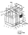
さて、本実施例では、上記コンデンサ1、エバポレータ2、第1〜第4の吸着器4〜7、中間熱交換器12、コンデンサ16、切替弁等の真空系機器を1つの真空容器内に構成することを特徴としている。
即ち、図1は真空容器を示している。この図1において、真空容器21は上下仕切板22により上下に仕切られている。この場合、上下仕切板22の下側は3つの部屋に仕切られており、各部屋に、コンデンサ1、エバポレータ2、中間熱交換器12が構成されている。
【0032】
また、上下仕切板22の上側は下側の部屋と交差するように4つの部屋に仕切られており、各部屋に、第1〜第4の吸着器4〜7が構成されている。
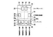
ここで、図3に示すように、上下仕切板22においてコンデンサ1と第1及び第2の吸着器4及び5とを夫々仕切る部位には第1及び第2の窓23及び24が形成されており、当該窓23及び24はドア25により開閉されるようになっている。この場合、第1の窓23の開放状態でコンデンサ1と第1の吸着器4とが連通し、第2の窓24の開放状態でコンデンサ1と第2の吸着器5とが連通する(図4参照)。
【0033】
また、上下仕切板22においてエバポレータ2と第1及び第2の吸着器4及び5とを夫々仕切る部位には第3の窓26及び第4の窓27が形成されており、当該窓26及び27がドア25により開閉されるようになっている。この場合、第3の窓26の開放状態でエバポレータ2と第1の吸着器4とが連通し、第4の窓27の開放状態でエバポレータ2と第2の吸着器5とが連通する。
【0034】
さらに、上下仕切板22において中間熱交換器12と第1,第4の吸着器4,7とを夫々仕切る部位には第5及び第6の窓28及び29が形成されており、当該窓28及び29がドア25により開閉されるようになっている。この場合、第5の窓28の開放状態で中間熱交換器12と第3の吸着器6とが連通し、第6の窓29の開放状態で中間熱交換器12と第4の吸着器7とが連通する。
【0035】
尚、図示はしていないが、コンデンサ1にはコンデンサ16が一体に設けられており、中間熱交換器12は、コンデンサ16を介して第3の吸着器6若しくは第4の吸着器7の何れかに選択的に連通するようになっている。
【0036】
即ち、上下仕切り板22において、コンデンサ16と第3及び第4の吸着器6及び7とを夫々仕切る部位には第7及び第8の窓29a及び29bが形成されており、当該窓29a及び29bはドア25により開閉されるようになっている。この場合、第7の窓29aの開放状態でコンデンサ16と第3の吸着器6とが連通し、第8の窓29bの開放状態でコンデンサ16と第4の吸着器7とが連通する。
【0037】
そして、真空容器21に構成されたコンデンサ1及び16、中間熱交換器12、第1〜第4の吸着器4〜7には、図1で示した接続関係を満足するように配管が接続されている。
つまり、コンデンサ1は、配管30及び31を通じて放熱器19と接続されている。
【0038】
中間熱交換器12は、配管32を通じて4方弁10と接続されていると共に配管33を通じて3方弁14と接続されている。
エバポレータ2は、配管34及び35を通じて車室内側に設けられた室内熱交換器と接続されている。
【0039】
第1の吸着器4は、配管36を通じて4方弁10と接続されていると共に、配管37を通じて3方弁14及び3方弁18と接続されている。
第2の吸着器5は、配管38を通じて4方弁10と接続されていると共に、配管39を通じて3方弁14及び3方弁20と接続されている。
第3の吸着器6は、配管40を通じて4方弁17と接続されていると共に、配管41を通じて3方弁18と接続されている。
第4の吸着器7は、配管42を通じて4方弁17と接続されていると共に、配管43を通じて3方弁20と接続されている。
尚、図2で示したポンプ11は図示を省略した。
【0041】
ところで、図1示す真空容器21には、図5に示すように当該真空容器21と接続された各配管30〜43のうちコンデンサ1及び中間熱交換器12にエンジン冷却水を供給するための配管30〜33を取外した形態で樹脂カバー44が装着されている。
【0042】
ここで、樹脂カバー44には放熱器19と接続するための配管口45,46及びエンジン側と接続するための配管口(図示せず)が設けられていると共に、配管30〜33に相当する流体流路47〜50(図6参照)が一体に設けて構成されており、その流体流路47〜50をコンデンサ1及び中間熱交換器12に接続するようになっている。
【0043】
上記構成のものによれば、エバポレータ2を冷却するために第1〜第4の吸着器4〜7、中間熱交換器12等の真空系機器を設けた構成において、全ての真空系機器を1つの真空容器21に収納するように構成したので、真空系機器が独立して構成されている従来例のものと違って、真空系機器の維持,管理を容易に行うことができる。
また、樹脂カバー44の表面に流体流路47〜50を沿わせて設けることができるので、配管の突出を抑制でき、以て全体の小形化を図ることができる。
【0044】
図7は本発明の第2実施例を示している。この第2実施例は、真空容器21の表面に配管を一体に形成したことを特徴とする。
即ち、真空容器21の金属表面に強度向上を兼ねるリブ51を形成し、そのリブ51により流体流路52を形成するようにしている。
このような構成によれば、樹脂カバー44に配管を一体に設ける必要がなくなり、さらに全体の小形化を図ることができる。
【0045】
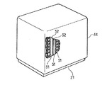
図8及び図9は本発明の第3実施例を示している。この第3実施例は、真空容器21において吸着器を構成する部屋の内壁面を加熱するように構成したことを特徴とする。
【0046】
即ち、真空容器21の表面にリブ53によって高温のエンジン冷却水を通過させる加熱手段(流体流路)としての水蒸気凝縮防止流路54を形成するようにしたものである。この場合、水蒸気凝縮防止流路54に供給するエンジン冷却水としては、吸着剤9の再生に利用したエンジン冷却水を水蒸気凝縮防止流路54に通過させてからエンジン側に戻すようにしている。
【0047】
このような構成によれば、第1〜第4の吸着器4〜7を構成する部屋の内壁面を加熱することができるので、内壁面に水蒸気が凝縮して冷房能力が低下してしまうことを防止できる。つまり、真空容器21の内壁面が低温の場合、部屋内の水蒸気が凝縮して水滴となって滞留するので、本来エバポレータ2或いは中間熱交換器12との間で行われる水蒸気の吸着が、部屋の内壁面に付着した水滴との間で行われてしまって、冷房能力の低下を生じるからである。
【0048】
本発明は、上記実施例にのみ限定されるものではなく、次のように変形または拡張できる。
中間熱交換器12を用いることなく、後段の吸着器により前段の吸着器を冷却するような構成の吸着式冷凍機に適用するようにしてもよい。
第4実施例において、真空容器21の部屋を加熱する加熱手段としては、電熱ヒータ、エンジンの排熱を利用するようにしてもよい。
【図面の簡単な説明】
【図1】 本発明の第1実施例における全体構成を概略的に示す斜視図
【図2】 全体の接続関係を示す模式図
【図3】 上下仕切板の平面図
【図4】 コンデンサに対応する上下仕切板の斜視図
【図5】 全体の斜視図
【図6】 流体流路の断面を示す斜視図
【図7】 本発明の第2実施例を示す全体の斜視図
【図8】 本発明の第3実施例における要部を破断して示す斜視図
【図9】 要部の縦断面図
【符号の説明】
1はコンデンサ、2はエバポレータ、4〜7は吸着器、9は吸着剤、12は中間熱交換器、21は真空容器、30〜43は配管、44は樹脂カバー、47〜50は流体流路、54は水蒸気凝縮防止流路(加熱手段、流体流路)である。[0001]
BACKGROUND OF THE INVENTION
The present invention relates to an adsorption refrigerator that efficiently cools an evaporator by providing a plurality of stages of adsorbers.
[0002]
[Prior art]
Conventionally, as this type of adsorption refrigerator, two adsorbers filled with an adsorbent such as silica gel or zeolite are provided, and the adsorber for performing the adsorption process is connected to the evaporator, and the desorption process Is configured by connecting an adsorber that performs the above operation with a capacitor.
[0003]
In this case, since the gas refrigerant evaporated by the evaporator is adsorbed by the adsorber that performs the adsorption process, the refrigerant continues to evaporate in the evaporator, and the gas refrigerant is supplied to the condenser from the adsorber that performs the desorption process. Since it is liquefied, the cooling action of the evaporator can be continued by supplying the refrigerant from the condenser to the evaporator.
[0004]
Then, the desorption process is performed by heating the adsorber after the adsorption process is completed, and the adsorption process is performed by cooling the adsorber after the desorption process is completed. Thus, the gas refrigerant generated in the evaporator can be adsorbed by the adsorber that has performed the adsorption process, and the gas refrigerant can be supplied to the condenser from the adsorber that has performed the desorption process. Therefore, the cooling action of the evaporator can be continued.
[0005]
Accordingly, by blowing air into the vehicle interior through the evaporator, heat exchange is performed between the air passing through the evaporator and the refrigerant evaporating in the evaporator, so that cool air can be blown into the vehicle interior.
[0006]
By the way, although the cooling capacity of the evaporator depends on the refrigerant adsorption rate of the adsorbent, since the refrigerant adsorption rate of the adsorbent is low, it is necessary to fill the adsorber with a large amount of adsorbent in order to increase the cooling capacity of the evaporator. However, there is a drawback that the adsorber becomes larger and the weight increases.
[0007]
Therefore, a plurality of adsorbers are provided in multiple stages, and the pre-stage adsorber connected to the evaporator is cooled by the post-stage adsorber to increase the refrigerant adsorption rate of the pre-stage adsorber and connected to the pre-stage adsorber. Adsorption-type refrigerators that improve the cooling capacity of the evaporator are considered.
[0008]
[Problems to be solved by the invention]
However, in the above conventional configuration, a plurality of subsequent adsorbers are provided corresponding to the first and second adsorbers, and all the adsorbers are maintained in vacuum, and an evaporator and a capacitor are provided. It is necessary to selectively connect each adsorber with a vacuum pipe and a switching valve. For this reason, it is difficult to control the degree of vacuum of the vacuum system equipment, and there is a drawback that the apparatus is increased in size.
[0009]
The present invention has been made in view of the above circumstances, and its purpose is to cool these adsorbers in addition to an adsorber that adsorbs the gas refrigerant evaporated by the evaporator and an adsorber that supplies the gas refrigerant to the condenser. Adsorption type refrigerator having a vacuum system such as a plurality of adsorbers and maintaining the inside of these vacuum systems in a vacuum with easy management of the degree of vacuum and miniaturization of the whole Is to provide.
[0010]
[Means for Solving the Problems]
According to the invention of
[0011]
In addition , the cover attached to the vacuum vessel is provided with a fluid flow path for supplying heating / cooling fluid to a predetermined device, so that the piping work can be simplified and the size can be reduced. Can do.
[0012]
According to the second aspect of the present invention, since a fluid flow path for supplying heating / cooling fluid to a predetermined device can be provided on the surface of the vacuum vessel, it is not necessary to provide a special pipe.
[0013]
According to the invention of
[0014]
According to the invention of
[0015]
DETAILED DESCRIPTION OF THE INVENTION
Hereinafter, a description will be given of a first embodiment of the present invention is applied to a vehicle air conditioner with reference to FIGS.
FIG. 2 schematically shows the overall connection relationship. In FIG. 2, the outlet of the
[0016]
Further, the inlet of the
On the other hand, a
[0017]
These first to
[0018]
Here, the outlet of the cooling and
[0019]
Water is stored in the
[0020]
The inlet of the cooling and
[0021]
The inlet of the cooling and
Further, the
[0022]
Here, the
[0023]
The operation of the above configuration will be briefly described. In this case, the first and
[0024]
That is, in the connection relationship of FIG. 2, the
[0025]
At this time, the cooling water circulates between the
[0026]
Further, since the
Therefore, since water can be supplied from the
[0027]
On the other hand, the
At this time, since the cooling water passing through the
[0028]
Further, since the
[0029]
With the above operation, the cooling of the
[0030]
Then, by switching a predetermined valve when a predetermined time has elapsed, the first and
[0031]
In this embodiment, the
That is, FIG. 1 shows a vacuum vessel. In FIG. 1, the
[0032]
Moreover, the upper side of the upper and
Here, as shown in FIG. 3, first and
[0033]
In addition, a third window 26 and a
[0034]
Further, fifth and
[0035]
Although not shown in the figure, the
[0036]
That is, in the upper and
[0037]
Then, piping is connected to the
That is, the
[0038]
The
The
[0039]
The
The
The
The
The illustration of the
[0041]
Incidentally, in the
[0042]
Here, the
[0043]
According to the above configuration, in order to cool the
Moreover, as it can be provided and along a
[0044]
FIG. 7 shows a second embodiment of the present invention. The second embodiment is characterized in that piping is integrally formed on the surface of the
That is,
According to such a configuration, it is not necessary to provide piping integrally with the
[0045]
8 and 9 show a third embodiment of the present invention. The third embodiment is characterized in that the
[0046]
That is, a water vapor condensation
[0047]
According to such a structure, since the inner wall surface of the room which comprises the 1st-4th adsorbers 4-7 can be heated, water vapor | steam condenses on an inner wall surface, and cooling capacity will fall. Can be prevented. That is, when the inner wall surface of the
[0048]
The present invention is not limited to the above embodiment, and can be modified or expanded as follows.
You may make it apply to the adsorption | suction type refrigerator of the structure which cools a front | former stage adsorber by a back | latter stage adsorber, without using the
In the fourth embodiment, as a heating means for heating the chamber of the
[Brief description of the drawings]
FIG. 1 is a perspective view schematically showing an overall configuration in a first embodiment of the present invention. FIG. 2 is a schematic diagram showing an overall connection relationship. FIG. 3 is a plan view of upper and lower partition plates. perspective view FIG. 5 is a perspective view of the entire FIG. 6 is a perspective view of the whole showing a second embodiment of a perspective view showing a cross-section of the
1 is a condenser, 2 is an evaporator, 4 to 7 are adsorbers, 9 is an adsorbent, 12 is an intermediate heat exchanger, 21 is a vacuum vessel, 30 to 43 are piping, 44 is a resin cover, and 47 to 50 are fluid flow paths , 54 are water vapor condensation prevention flow paths (heating means, fluid flow paths).
Claims (4)
気冷媒を液化して前記エバポレータに与えるコンデンサと、
吸着工程と脱着工程とを交互に実行するように設けられ、吸着工程の実行により前記エバポレータで蒸発した気冷媒を吸着すると共に脱着工程の実行により気冷媒を前記コンデンサに与える吸着剤が収納された第1の吸着器及び第2の吸着器と、
前記第1及び第2の吸着器に対応して設けられ吸着工程を実行する吸着器を冷却するように設けられた第3及び第4の吸着器と、
前記エバポレータ、コンデンサ、第1乃至第4の吸着器の接続関係を切替える複数の切替弁とを備えた吸着式冷凍機において、
前記エバポレータ、コンデンサ、第1乃至第4の吸着器、複数の切替弁を1つの真空容器に収納して構成すると共に、
前記真空容器に被着されるカバーを備え、
前記カバーに、所定の機器に加熱・冷却流体を供給するための流体流路を一体に設けたことを特徴とする吸着式冷凍機。An evaporator for evaporating the liquid refrigerant;
A condenser that liquefies the gaseous refrigerant and gives it to the evaporator;
An adsorption process is provided to alternately execute an adsorption process and a desorption process, and an adsorbent that adsorbs the gas refrigerant evaporated by the evaporator by executing the adsorption process and gives the gas refrigerant to the capacitor by executing the desorption process is stored. A first adsorber and a second adsorber;
Third and fourth adsorbers provided to cool the adsorbers that are provided corresponding to the first and second adsorbers and perform the adsorption process;
In the adsorption refrigeration machine comprising the evaporator, the condenser, and a plurality of switching valves for switching the connection relationship of the first to fourth adsorbers,
The evaporator, the condenser, the first to fourth adsorbers, and the plurality of switching valves are housed in a single vacuum container ,
A cover to be attached to the vacuum vessel;
An adsorption refrigeration machine, wherein a fluid flow path for supplying heating / cooling fluid to a predetermined device is provided integrally with the cover .
気冷媒を液化して前記エバポレータに与えるコンデンサと、
吸着工程と脱着工程とを交互に実行するように設けられ、吸着工程の実行により前記エバポレータで蒸発した気冷媒を吸着すると共に脱着工程の実行により気冷媒を前記コンデンサに与える吸着剤が収納された第1の吸着器及び第2の吸着器と、
前記第1及び第2の吸着器に対応して設けられ吸着工程を実行する吸着器を冷却するように設けられた第3及び第4の吸着器と、
前記エバポレータ、コンデンサ、第1乃至第4の吸着器の接続関係を切替える複数の切替弁とを備えた吸着式冷凍機において、
前記エバポレータ、コンデンサ、第1乃至第4の吸着器、複数の切替弁を1つの真空容器に収納して構成すると共に、
前記真空容器の表面に、所定の機器に加熱・冷却流体を供給するための流体流路を一体に設けたことを特徴とする吸着式冷凍機。 An evaporator for evaporating the liquid refrigerant;
A condenser that liquefies the gaseous refrigerant and gives it to the evaporator;
An adsorption process is provided to alternately execute an adsorption process and a desorption process, and an adsorbent that adsorbs the gas refrigerant evaporated by the evaporator by executing the adsorption process and gives the gas refrigerant to the capacitor by executing the desorption process is stored. A first adsorber and a second adsorber;
Third and fourth adsorbers provided to cool the adsorbers that are provided corresponding to the first and second adsorbers and perform the adsorption process;
In the adsorption refrigeration machine comprising the evaporator, the condenser, and a plurality of switching valves for switching the connection relationship of the first to fourth adsorbers,
The evaporator, the condenser, the first to fourth adsorbers, and the plurality of switching valves are housed in a single vacuum container,
An adsorption refrigeration machine, wherein a fluid flow path for supplying a heating / cooling fluid to a predetermined device is integrally provided on a surface of the vacuum vessel .
気冷媒を液化して前記エバポレータに与えるコンデンサと、
吸着工程と脱着工程とを交互に実行するように設けられ、吸着工程の実行により前記エバポレータで蒸発した気冷媒を吸着すると共に脱着工程の実行により気冷媒を前記コンデンサに与える吸着剤が収納された第1の吸着器及び第2の吸着器と、
前記第1及び第2の吸着器に対応して設けられ吸着工程を実行する吸着器を冷却するように設けられた第3及び第4の吸着器と、
前記エバポレータ、コンデンサ、第1乃至第4の吸着器の接続関係を切替える複数の切替弁とを備えた吸着式冷凍機において、
前記エバポレータ、コンデンサ、第1乃至第4の吸着器、複数の切替弁を1つの真空容器に収納して構成すると共に、
前記真空容器の表面を加熱する加熱手段を備え、
前記加熱手段により前記吸着器の内壁面を加熱することを特徴とする吸着式冷凍機。 An evaporator for evaporating the liquid refrigerant;
A condenser that liquefies the gaseous refrigerant and gives it to the evaporator;
An adsorption process is provided to alternately execute an adsorption process and a desorption process, and an adsorbent that adsorbs the gas refrigerant evaporated by the evaporator by executing the adsorption process and gives the gas refrigerant to the capacitor by executing the desorption process is stored. A first adsorber and a second adsorber;
Third and fourth adsorbers provided to cool the adsorbers that are provided corresponding to the first and second adsorbers and perform the adsorption process;
In the adsorption refrigeration machine comprising the evaporator, the condenser, and a plurality of switching valves for switching the connection relationship of the first to fourth adsorbers,
The evaporator, the condenser, the first to fourth adsorbers, and the plurality of switching valves are housed in a single vacuum container,
Heating means for heating the surface of the vacuum vessel;
An adsorption refrigerator that heats the inner wall surface of the adsorber by the heating means .
前記真空容器の表面に、加熱流体が通過する加熱流体流路を設け、
前記加熱流体流路と前記真空容器内において前記吸着器を構成する壁面とを伝熱的に設けて構成したことを特徴とする請求項3記載の吸着式冷凍機。 The heating means includes
A heating fluid passage through which the heating fluid passes is provided on the surface of the vacuum vessel,
The adsorption refrigerator according to claim 3, wherein the heating fluid channel and a wall surface constituting the adsorber are provided in a heat transfer manner in the vacuum vessel .
Priority Applications (1)
| Application Number | Priority Date | Filing Date | Title |
|---|---|---|---|
| JP00547996A JP3831964B2 (en) | 1996-01-17 | 1996-01-17 | Adsorption type refrigerator |
Applications Claiming Priority (1)
| Application Number | Priority Date | Filing Date | Title |
|---|---|---|---|
| JP00547996A JP3831964B2 (en) | 1996-01-17 | 1996-01-17 | Adsorption type refrigerator |
Publications (2)
| Publication Number | Publication Date |
|---|---|
| JPH09196494A JPH09196494A (en) | 1997-07-31 |
| JP3831964B2 true JP3831964B2 (en) | 2006-10-11 |
Family
ID=11612390
Family Applications (1)
| Application Number | Title | Priority Date | Filing Date |
|---|---|---|---|
| JP00547996A Expired - Fee Related JP3831964B2 (en) | 1996-01-17 | 1996-01-17 | Adsorption type refrigerator |
Country Status (1)
| Country | Link |
|---|---|
| JP (1) | JP3831964B2 (en) |
Cited By (1)
| Publication number | Priority date | Publication date | Assignee | Title |
|---|---|---|---|---|
| KR20190052452A (en) * | 2017-11-08 | 2019-05-16 | 한국생산기술연구원 | Adsorption cooling device having multi adsorption tower and methdo for cooling using the same |
Families Citing this family (8)
| Publication number | Priority date | Publication date | Assignee | Title |
|---|---|---|---|---|
| CN100419345C (en) * | 2005-12-13 | 2008-09-17 | 财团法人工业技术研究院 | Solid adsorptive refrigerator |
| JP2007057100A (en) * | 2006-09-20 | 2007-03-08 | Fuji Electric Systems Co Ltd | Vacuum container |
| JP5024815B2 (en) * | 2006-11-21 | 2012-09-12 | 独立行政法人産業技術総合研究所 | Adsorbent particle circulation type refrigerator |
| JP4821746B2 (en) * | 2007-09-20 | 2011-11-24 | 株式会社デンソー | Adsorption heat exchanger |
| JP5315893B2 (en) * | 2008-09-24 | 2013-10-16 | 富士通株式会社 | Adsorption heat pump |
| CN102338499A (en) * | 2010-07-15 | 2012-02-01 | 中兴电工机械股份有限公司 | Separated solid-adsorption-type refrigerating system |
| CN109556314B (en) * | 2018-10-09 | 2021-03-30 | 宁波工程学院 | Multi-stage adsorption refrigeration method |
| KR102031729B1 (en) * | 2018-11-27 | 2019-11-08 | 삼중테크 주식회사 | Adsorption chiller comprising a rotary switching valve |
-
1996
- 1996-01-17 JP JP00547996A patent/JP3831964B2/en not_active Expired - Fee Related
Cited By (2)
| Publication number | Priority date | Publication date | Assignee | Title |
|---|---|---|---|---|
| KR20190052452A (en) * | 2017-11-08 | 2019-05-16 | 한국생산기술연구원 | Adsorption cooling device having multi adsorption tower and methdo for cooling using the same |
| KR101988550B1 (en) | 2017-11-08 | 2019-06-13 | 한국생산기술연구원 | Adsorption cooling device having multi adsorption tower and methdo for cooling using the same |
Also Published As
| Publication number | Publication date |
|---|---|
| JPH09196494A (en) | 1997-07-31 |
Similar Documents
| Publication | Publication Date | Title |
|---|---|---|
| JP4192385B2 (en) | Adsorption type refrigerator | |
| JPH02230068A (en) | Absorption freezer and its operating method | |
| JP3831964B2 (en) | Adsorption type refrigerator | |
| JP5803704B2 (en) | Refrigeration system | |
| JP3831959B2 (en) | Adsorption type refrigerator | |
| JP3959805B2 (en) | Engine driven refrigeration system | |
| JP4066485B2 (en) | Refrigeration equipment | |
| JP4074399B2 (en) | Operation method of adsorption refrigeration system | |
| JP2005098586A (en) | Air conditioner | |
| JPH05272833A (en) | Control method for freezing output of adsorption type freezer and adsorption type freezer capable of controlling freezing output | |
| JP3668764B2 (en) | Humidity control device | |
| JPH09196493A (en) | Adsorption refrigerating apparatus | |
| JP4565539B2 (en) | Operation method of adsorption refrigerator | |
| JP4022944B2 (en) | Adsorption refrigeration system | |
| JPH04316966A (en) | Adsorption type refrigerating machine and operating method thereof | |
| JP3348615B2 (en) | Adsorption refrigeration equipment | |
| JP3404947B2 (en) | Heat exchanger and adsorption refrigeration system | |
| JP3334320B2 (en) | Air conditioner | |
| JP2002048428A (en) | Adsorption type refrigerating machine | |
| JPH11223416A (en) | Refrigerating device | |
| JP3316892B2 (en) | Operating method of adsorption refrigeration system | |
| JP4300677B2 (en) | Adsorption type refrigerator | |
| JP2016200323A (en) | Refrigeration system | |
| JP3921744B2 (en) | Adsorption refrigeration system | |
| JPH11223414A (en) | Refrigerating device |
Legal Events
| Date | Code | Title | Description |
|---|---|---|---|
| A131 | Notification of reasons for refusal |
Free format text: JAPANESE INTERMEDIATE CODE: A131 Effective date: 20051004 |
|
| A521 | Written amendment |
Free format text: JAPANESE INTERMEDIATE CODE: A523 Effective date: 20051130 |
|
| TRDD | Decision of grant or rejection written | ||
| A01 | Written decision to grant a patent or to grant a registration (utility model) |
Free format text: JAPANESE INTERMEDIATE CODE: A01 Effective date: 20060627 |
|
| A61 | First payment of annual fees (during grant procedure) |
Free format text: JAPANESE INTERMEDIATE CODE: A61 Effective date: 20060710 |
|
| R150 | Certificate of patent or registration of utility model |
Free format text: JAPANESE INTERMEDIATE CODE: R150 |
|
| LAPS | Cancellation because of no payment of annual fees |