JP3830770B2 - Hologram recording medium and hologram type information recording / reproducing apparatus - Google Patents
Hologram recording medium and hologram type information recording / reproducing apparatus Download PDFInfo
- Publication number
- JP3830770B2 JP3830770B2 JP2001102405A JP2001102405A JP3830770B2 JP 3830770 B2 JP3830770 B2 JP 3830770B2 JP 2001102405 A JP2001102405 A JP 2001102405A JP 2001102405 A JP2001102405 A JP 2001102405A JP 3830770 B2 JP3830770 B2 JP 3830770B2
- Authority
- JP
- Japan
- Prior art keywords
- light
- hologram
- hologram recording
- recording medium
- recording
- Prior art date
- Legal status (The legal status is an assumption and is not a legal conclusion. Google has not performed a legal analysis and makes no representation as to the accuracy of the status listed.)
- Expired - Fee Related
Links
Images


Description
【0001】
【発明の属する技術分野】
本発明は、ホログラム記録媒体、及びホログラム型情報記録再生装置に係るものであり、特に干渉縞を記録層内部の屈折率差で記録する体積ホログラム記録媒体及びホログラム型情報記録再生装置に関する。
【0002】
【従来の技術】
近年、大量のデータを扱うことが可能となる情報記録システムとして、ホログラム技術が注目されている。ホログラム技術を用いると、異なる角度で参照光を照射することによって同一領域に多重書き込みを行うことが可能であり、体積型ホログラム記録媒体を用いることで3次元的な記録が可能である。
図12に示す透過型ホログラム型情報記録再生装置の概略図を用いて、装置の仕組みを説明する。ホログラム型情報記録再生装置はホログラム記録媒体117中の記録領域118に2つの方向から、可干渉性の光である記録光122及び参照光121を照射することにより、情報の記録を行う。記録光122は記録する情報に対応して空間変調器115によって波長若しくは位相が変調され、記録光122と参照光121は記録領域118において干渉する。ホログラム記録媒体117は干渉パターンに応じて屈折率が変化する性質を有するため、情報の内容に応じた屈折率変化が記録領域118に記録される。
【0003】
次に、ホログラム情報の再生方法を説明する。情報の再生は、参照光121のみを用いて行われる。記録光は電磁シャッター116を閉じることにより遮断され、ホログラム記録媒体117には参照光121のみが入射する。参照光121はあらかじめ記録時に屈折率を変化した記録領域118において回折を生じるため、記録光が入射していないにも関わらず、記録時に照射した記録光122と同じ情報を有する回折光が光検出器120へ到達し、情報が再生される。
【0004】
【発明が解決しようとする課題】
上述のようにホログラム型情報記録再生装置は構成されており、ホログラム型情報記録再生装置、特にホログラム記録媒体に関して盛んに研究が行われ、銀塩乳剤や、重クロム酸ゼラチン、フォトポリマーなどを用いた記録媒体が提案されている。しかし従来の技術では様々の欠点が生じている。以下に従来の技術にかかるホログラム記録媒体の特徴と、その欠点について述べる。
【0005】
(A)銀塩乳剤:銀塩乳剤は、ゼラチン層中に分散したハロゲン化銀に露光し、銀を析出させることによりホログラムを記録する。銀塩乳剤をホログラム型情報記録媒体として用いた場合、高い感度を実現できるがその反面、露光後に現像、洗浄、漂白といった化学処理を必要とし、これらの処理が煩雑であるという欠点がある。また、化学処理や乾燥によりゼラチン層が変形し、記録された情報が正確に再生されないなどの欠点も存在する。
【0006】
(B)重クロム酸ゼラチン:重クロム酸ゼラチンは、ゼラチン層を重クロム酸アンモニウム溶液に浸して感光性をもたせた材料に露光し、ゼラチンを硬化させることによりホログラムを記録する。重クロム酸ゼラチンをホログラム型情報記録媒体として用いた場合、露光後に洗浄、イソプロピルアルコールによる脱水処理を必要とし、処理が煩雑であるという欠点があり、またそれらの処理によってゼラチン層が変形したり、ゼラチン層が水分に弱いなどの欠点が存在する。
【0007】
(C)フォトポリマー:フォトポリマーは露光によりモノマーを重合させて屈折率を変化させることによってホログラムを記録する。フォトポリマーをホログラム型情報記録媒体として用いた場合、情報の記録がモノマーの重合によって行われるため、重合反応による体積の変化が本質的に避けられないという欠点が存在する。
【0008】
(D)フォトリフラクティブ結晶:フォトリフラクティブ結晶としては鉄イオンをドープしたニオブ酸リチウムやチタン酸バリウムなどが一般に使われており、露光により結晶内で電荷を空間的に分離し、電荷の再分布により生じる内部電場によって屈折率を変化させることによりホログラムを記録する。フォトリフラクティブ結晶をホログラム型情報記録媒体として用いる場合、大きな結晶を作製することが困難で高価である、個体により特性が異なるなどの欠点が存在する。
【0009】
(E)フォトリフラクティブポリマー:フォトリフラクティブポリマーは、露光による電荷発生、電荷輸送、電気光学効果などの性能を有した材料であり、フォトリフラクティブ結晶と同様に、露光により電荷を空間的に分離し、電荷の再分布により生じる内部電場によって屈折率を変化させることによりホログラムを記録する。フォトリフラクティブポリマーをホログラム型情報記録媒体として用いる場合、露光により形成される内部電場が小さいため媒体表面に電極を設け外部から電場を印加する必要があり、装置が複雑化するという欠点が存在する。
【0010】
(F)フォトレジスト:フォトレジストは露光により溶媒への溶解度を変化させ、現象により凹凸としてホログラムを記録する。フォトレジストをホログラム型情報記録媒体として用いる場合、光照射の他に現像処理工程が必要であり、また情報は凹凸として表面にホログラム記録されるため、本質的に体積ホログラムの作製が困難で、角度多重書き込みが困難などの欠点が存在する。
【0011】
上記した個別のホログラム記録媒体の欠点に加えて、上記ホログラム記録材料に共通するホログラム型情報記録媒体として用いる場合の問題点として次のことが挙げられる。すなわちホログラム記録材料は、書き込みの感度を得るために記録光の波長において大きな吸光係数を有する物質を使用している。また、一般に記録媒体内での記録光強度は指数関数的に減衰するため、従来のホログラム記録媒体では、ホログラムは記録媒体の記録層において記録光の入射側の表面近傍にのみ主に記録されることになる。そのためホログラム再生時の角度選択性に劣り、角度多重記録が困難である。又、大きな吸光係数を有するため回折効率も劣り、十分な感度を得ることができない。
【0012】
従って本発明の目的は、高い感度を有するホログラム記録媒体及びホログラム型情報記録再生装置を提供することである。
【0013】
本発明の他の目的は、高い回折効率を有するホログラム記録媒体及びホログラム型情報記録再生装置を提供することである。
【0014】
本発明の他の目的は、角度多重記録性能に優れたホログラム記録媒体及びホログラム型情報記録再生装置を提供することである。
【0015】
【課題を解決するための手段】
本発明の第1の特徴は透明基板と、その透明基板上の特定の位置に配置された、光反応促進剤と光反応促進剤を励起する波長の光が照射されることにより光反応促進剤と反応し前述の波長と異なる波長の光に対する吸光係数が変化する色素とを含むことを特徴とするホログラム記録層と、ホログラム記録層上に配置された透明基板と、前述の透明基板及びホログラム記録層上の透明基板の間であってホログラム記録層以外の領域に配置された両透明基板を所定の距離をもって結合するスペーサーとから構成されたホログラム記録媒体である点である。ここで光反応促進剤とは、特定の波長を有する光を照射することにより活性化され、ホログラム記録層に含まれる色素と反応する物質をいう。また、色素とは、特定波長の光を照射された光反応促進剤と反応し、その結果前述の特定波長と別の波長に対する吸光係数が変化するものをいい、例えば光反応促進剤が光酸発生剤である場合、発生した酸と反応して別の波長に対する吸光係数が変化する色素である。透明基板とは、透明な基板であればよく、無機的材料及び有機的材料を含む概念である。
【0016】
本発明の第1の特徴によれば、ホログラム記録媒体に照射する光の波長と、ホログラム記録媒体中で吸光係数の変化する光の波長が異なったものとなる。従って、記録した情報を読みとる際に参照光に対するホログラム記録媒体の吸光係数が変化しないため、高い回折効率を得ることが可能となる。また、光源から照射される光に反応する役割を果たす光反応促進剤と、光源の波長と異なる特定波長の光に対して吸光係数が変化する役割を果たす色素という2つの物質によって情報を記録するため、それぞれの役割に適した物質を別々に選択することが可能となる。すなわち1つの物質でこれら2つの役割を果たす場合に比べて物質の選択の幅が広くなり、より良質なホログラム記録媒体を得ることが可能となる。
【0017】
なお、光反応促進剤としては光酸発生剤若しくは光ラジカル発生剤であることが望ましい。ここで光酸発生剤とは特定波長の光が照射されることにより酸を発生する物質をいい、光ラジカル発生剤とは、特定波長の光が照射されることにより、ラジカルを発生する物質をいう。光反応促進剤に光酸発生剤若しくは光ラジカル発生剤を用いた場合、光酸発生剤により生じた酸またはラジカルは、連鎖的に複数の色素と反応するため1個の光子が入射することにより複数の物質の特定波長の光の吸光係数が変化する。すなわち高感度のホログラム記録媒体を実現することが可能である。
【0018】
本発明の第2の特徴は、透明基板と、その透明基板上に配置された、光反応促進剤と光反応促進剤を励起する波長の光が照射されることにより光反応促進剤と反応し前記波長と異なる波長の光に対する吸光係数が変化する色素とを含むことを特徴とするホログラム記録層と、ホログラム記録層上に配置された透明基板と、前述の透明基板及び前記ホログラム記録層上の透明基板の間であってホログラム記録層以外の領域に配置された両透明基板を所定の距離を持って結合するスペーサーとから構成されたことを特徴とする、ホログラム記録媒体と、ホログラム記録媒体を固定する支持体と、前述の光反応促進剤を励起する波長を有する光源と、光源から得られる記録光の光路上に配置された空間変調器と、前述の光源から得られる参照光と記録光をホログラム記録層で交差させる光学系と、ホログラム記録媒体を通過した記録光の光路上に配置した光検出器とを有することを特徴とするホログラム型情報記録再生装置である点にある。ここで、光反応促進剤、色素、透明基板は、本発明の第1の特徴におけるものと同様の概念であり、空間変調器とは、光源から得られる記録光の位相若しくは波長を空間的に変調する装置である。
【0019】
また、第2の特徴におけるホログラム型情報記録再生装置は、ホログラム記録媒体若しくはホログラム記録媒体を固定するための支持体の周囲にホログラム記録媒体を加熱するための加熱装置を有することが望ましい。加熱装置を有することで、特定波長の光を照射されることによって生じた酸が、熱によって周囲に効率よく拡散することが可能となる。従って周囲に存在する複数の色素と連鎖的に反応し、記録に際して高い感度を有するホログラム型情報記録再生装置を提供することができる。
【0020】
【発明の実施の形態】
以下、図面を参照して本発明の実施の形態を説明する。図面の記載において、同一あるいは類似部分には同一あるいは類似な符号を付している。ただし、図面は模式的なものであり、ホログラム記録媒体の厚みと幅の関係、記録装置の構成物品の大きさの比率などは、現実のものとは異なることに留意するべきである。また、図面の相互間においても互いの寸法の関係や比率が異なる部分が含まれていることはもちろんである。
【0021】
(第1の実施の形態)
本発明の第1の実施の形態にかかる透過型ホログラム型情報記録再生装置に用いるホログラム記録媒体の構造について、図1及び図2を用いて以下に説明する。
【0022】
第1の実施の形態にかかるホログラム記録媒体は透明基板6aと、透明基板6aの上に配置されたホログラム記録層4bと、ホログラム記録層4bの上に配置された透明基板6bと、透明基板6a,6bの間に配置されたスペーサー5からなる。ホログラム記録層4bはマトリックス材1と、光酸発生剤2と、光照射により光酸発生剤2から発生する酸と反応して前述の光と異なる波長の光に対する吸光係数が変化する色素3によって構成されている。
【0023】
マトリックス材1は、ホログラム記録層の全体を構成する透明な物質である。マトリックス材1の材料として、第1の実施の形態ではポリメチルメタクリレートを用いる。光酸発生剤2は、励起光が照射されることによって化学反応を起こし、酸を発生するという特性を有する物質である。第1の実施の形態では光酸発生剤2としてジフェニルヨードニウムヘキサフルオロリン酸を用いる。色素3は、励起光の照射により光酸発生剤2から発生した酸と反応する特性を有する物質である。第1の実施の形態では色素3として化学式1で表される色素を用いる。
【0024】
【化1】

フッ素樹脂以外の材質をスペーサーとして用いても構わない。
【0025】
第1の実施の形態にかかるホログラム記録媒体を構成するホログラム記録層には上記のマトリックス材1、光酸発生剤2、色素3が、重量比にして96:2:2の割合で混在しており、これらの構成要素はホログラム記録層中に均一に分布している。光酸発生剤2及び色素3のマトリックス材1に対する割合は上記以外のものでも構わないが、光酸発生剤2及び色素3の割合が大きくなった場合、記録しようとする領域以外での光の吸収が無視できなくなる。それによりホログラム記録媒体の回折効率が低下するという欠点を生じることから、光酸発生剤2及び色素3の割合は一定の値以下とすることが望ましい。なお、図1及び図2はあくまで模式図であり、ホログラム記録媒体の構造の理解を容易にするためのものであってホログラム記録層4bについて、図1によって光酸発生剤2及び色素3の割合及びこれらを構成する粒子の大きさが決定されるのではない。
【0026】
マトリックス材1はポリメチルメタクリレート以外であっても、透明度が高くて容易に熱変形せず、ホログラム記録層中で発生する酸が熱拡散することが可能であればマトリックス材1として使用が可能である。具体的なマトリックス材1の原料としてポリスチレン、ポリカーボネート等の高分子化合物や、ゾル−ゲル法により作製された無機ガラス等が挙げられる。なお、ホログラム記録層中で発生する酸の熱拡散を容易とする観点からはマトリックス材1は非晶質構造をとることが望ましい。
【0027】
光酸発生剤2は、ジフェニルヨードニウムヘキサフルオロリン酸以外であっても、特定波長の励起光に対し活性化し、酸を発生するものであれば構わない。具体的にはスルフォニウム塩、ジアゾニウム塩、フォスフォニオウム塩等が光酸発生剤2の原料として挙げられる。
【0028】
色素3は上記の化学式1に記載した化合物以外であっても、酸と反応して吸光係数が変化するものであれば構わない。具体的には、シアニン、メロシアニン誘導体、クマリン誘導体、カルコン誘導体などが色素3の原料として挙げられる。
【0029】
次に、第1の実施の形態にかかるホログラム記録媒体の製造方法について説明する。
【0030】
(イ)マトリックス材1の原料であるポリメチルメタクリレートと、光酸発生剤2の原料であるジフェニルヨードニウムヘキサフルオロリン酸と、色素3の原料である上記の化学式1記載の色素を、重量比が96:2:2となるよう混合し、これを溶媒である乳酸エチルに溶解させる。
【0031】
(ロ)乳酸エチルに溶解させた原料を、3時間攪拌する。光酸発生剤2及び色素3とマトリックス材1を乳酸エチル中に均一に分散させるためである。
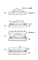
(ハ)溶解した原料が均一に分散した乳酸エチルを、図3(a)に示すように縦と横がそれぞれ3cm、厚さ0.5mmの大きさの石英ガラス6a上にキャストする。
【0032】
(ニ)石英ガラス6aの温度をヒーターを使って120度に加熱し、1時間その状態を維持する。その結果、溶媒の乳酸エチルは蒸発し、ホログラム記録層4bが得られる。
【0033】
(ホ)石英ガラス6a上であって、乳酸エチルがキャストされていない領域上に図3(b)に示すようにスペーサー5を配置する。スペーサー5はフッ素樹脂からなり、スペーサー5の高さは50μmである。さらに石英ガラス6aとは別の石英ガラス6bを用意し、この石英ガラス6bをスペーサー5及び上記のホログラム記録層4bの上部に配置する。
【0034】
(へ)石英ガラス6aを120度の温度に保ったままで、図3(c)に示すように石英ガラス6bの上部からホログラム記録層4bに対して均一に圧力を加える。ホログラム記録層4bは上からの圧力により横に引き延ばされる。2つのスペーサー5と石英ガラス6bが密着することにより、ホログラム記録層4bの厚さが均一に50μmとなる。
【0035】
(ト)図3(d)に示すようにホログラム記録層4bの厚さが均一になるまで整形された後、全体の温度を室温にまで下げる。全体の温度を下げるためには石英ガラス6aを低温の金属と接触させる方法や、水や液体窒素の中に投入する等の方法がある。この冷却工程を時間をかけて行ってもホログラム記録媒体は得られるが、急冷する方が望ましい。結果物が非晶質となると光酸発生剤2が熱拡散しやすい構造となり、より良質なホログラム記録媒体が得られるためである。以上で第1の実施の形態にかかるホログラム記録媒体が完成する。
【0036】
次に、第1の実施の形態にかかる透過型ホログラム情報記録再生装置の構造について図3を用いて説明する。
【0037】
第1の実施の形態にかかる透過型ホログラム情報記録再生装置は、アルゴンレーザー(λ=488nm)を用いた光源6と、光源6から生ずる可干渉光を参照光16と記録光17に分離する機能を有するビームスプリッター7を含む。また、記録光17の光路上にはビームスプリッター7の近くから順にミラー9、空間変調器11、電磁シャッター12が配置され、参照光16の光路上にはビームスプリッター7の近くから順にミラー8、ニュートラルデンシティーフィルター10が配置されている。ホログラム記録媒体4はその下部において銅板14によって固定され、銅板14には記録光及び参照光を通過させるための光通過孔14a、14bが設けられている。銅板14の下部にはヒーター18aが配置されている。ヒーター18aは温度コントローラー18cと接続され、温度コントローラー18cは熱電対18bを通してホログラム記録媒体4と接続されている。このことによりホログラム記録媒体4は温度コントローラー18cで設定した一定の温度に保たれる。また、記録光17と参照光16はホログラム記録媒体4の上面から入射し、ホログラム記録媒体内部の記録領域13において記録光17と参照光16は交差する構造となっている。また、記録光17がホログラム記録媒体を通過した後の記録光17の光路上には、光検出器15が配置されている。
【0038】
ここで光源6には、可干渉性の光を出射するものであって光酸発生剤2を励起して酸を発生させる波長を出射するものであれば、レーザー以外の光源を用いても構わない。また、レーザーを用いた場合でもアルゴンレーザー以外にHe−Neレーザー、YAGレーザー、半導体レーザーなどを用いることが可能である。特に半導体レーザーを用いた場合、光源6を小型化する事が可能でありホログラム情報記録再生装置を小型化する事ができるという利点が生ずる。また、半導体レーザーを光源6に使用した場合に、レーザーを構成する半導体の混晶の比を調整することで多様な発振波長を実現できるため、光酸発生剤に合わせて光源6の波長を変更でき、光酸発生剤2の選択の幅が広がるという利点もある。なお、光源6の発振波長は色素3を直接励起する波長でないことが望ましい。色素3が直接励起された場合、光源6の波長の光に対する吸光係数が変化することになり、回折効率の点で不利が生ずるためである。
【0039】
銅板14は、ホログラム記録媒体4を固定する目的で設けられるものであるため、固定できるものであれば銅板に限定する必要はない。銅板に参照光16及び記録光17を通すために光通過孔14a、14bを設けた構造以外に、銅板の代わりに透明な物質を用いた構造も望ましい。さらにはホログラム記録媒体4を側面から固定する構造も、光学的なロスが生じないため望ましい。
加熱装置は、ホログラム記録媒体4を加熱するためのものであって、この目的を達成するものである限り、様々な形態が可能である。ヒータをホログラム記録媒体に直接接触させて加熱する構造のものでも、ホログラム記録媒体周辺の環境の温度を上昇させることによる間接加熱構造のものや電磁波照射による輻射加熱でもよい。その他の手段であっても記録光未照射の領域の特性が変化せず、酸が周囲の色素にまで拡散できる方法であれば加熱装置として用いることが可能である。また、図3においては銅板14の下にヒーターが配置されているが、ヒーターの位置はこれに限定されず、ホログラム記録媒体4の側面部に配置することも可能であり、さらには銅板14の内部に含めても構わない。参照光16及び記録光17の光路を妨げず、効率的にホログラム記録媒体4を加熱できる位置であれば良い。
【0040】
また、空間変調器11は、記録光17の位相や波長などを空間的に変調する装置である。
【0041】
次に、第1の実施の形態にかかるホログラム記録媒体4及び透過型ホログラム情報記録再生装置を用いた情報の記録方法について図3及び図1を用いて以下に説明する。
【0042】
光源6から発射された光は、ビームスプリッター7で参照光16と記録光17に分離される。参照光16は、ビームスプリッター7を通過後、ミラー8によって方向が変更され、その後、記録光17と同一レベルの強度とするため、参照光16はニュートラルデンシティーフィルター10で強度の調整を受ける。光源6とニュートラルデンシティーフィルター10は記録領域13における参照光16及び記録光17の光強度が3mWとなるよう調整されている。その後参照光16はホログラム記録媒体4に入射する。記録光17は、ミラー9で方向を変換された後、空間変調器11で位相が変調され、開いた状態の電磁シャッター12を通過後、ホログラム記録媒体4に入射する。ここで空間変調器11で行われる記録光17の位相変調とは、記録領域13で記録する情報に応じて行われる。例えば、1の情報を記録する場合は記録領域13において記録光17と参照光16が強め合うように位相を変調し、0の情報を記録する場合は記録領域13において記録光17と参照光16が弱め合うよう位相を変調する。
【0043】
記録領域13において、参照光16と記録光17は交差する。この際に干渉がおこり、光が強めあった場合、記録領域13に存在する光酸発生剤2が光と反応して酸を発生する。
【0044】
記録領域13において記録しようとする情報に応じて光酸発生剤2より酸が発生した後、加熱装置によってホログラム記録媒体4が加熱される。ヒーター18aにより銅板14が加熱されるが、加熱温度を80度に保つため、温度コントローラー18cによって温度調整を行う。加熱は1分間行う。ホログラム記録媒体4が加熱されることによって、情報の記録の過程で発生した酸が、熱によって周囲に拡散し、複数の色素3と接触する。色素3は酸と反応して吸光係数が変化する性質を有するため、記録領域13における参照光16に対する屈折率が変化する。
【0045】
光の照射によって記録領域30における屈折率が変化する具体的なメカニズムは以下の通りである。
図5において、曲線1は第1の実施の形態にかかるホログラム記録媒体4全体の吸収スペクトルを示すグラフである。この曲線1は情報が記録されていない状態での吸収スペクトルを示している。また、曲線2は色素3による吸収スペクトルを示し、曲線3は光酸発生剤2による吸収スペクトルを示している。
【0046】
一方、図6は、ホログラム記録媒体4に対して波長が488nmのアルゴンレーザーを照射して、媒体を加熱する事により情報を記録した後の、ホログラム記録層4bにおける吸収スペクトルを示すグラフである。図5と図6を比較すると、光源の波長488nm付近の吸光度が減少するものの、それよりも488nmよりも短波長側、437nmをピークとする400〜460nmの領域で吸光度が顕著に減少する。これは、光酸発生剤2により発生した酸が、複数の色素3と連鎖的に反応するため、光酸発生剤2による吸光度よりも色素3による吸光度の現象の方が顕著に現れるためである。
【0047】
この吸収スペクトルとホログラム記録層4bの屈折率の間には、次の関係式が成立する。
【0048】
nλ 2=n∞2+Dλ02/(λ2−λ02) ・・・・(1)
ここでn∞は波長が無限大の時の屈折率、Dは媒体中の光を吸収するサイトの振動子強度により決まる値であり、λ0は吸光度が最大となる波長であり、第1の実施の形態にかかるホログラム記録媒体4では437nmである。ここで、情報の記録前と記録後を比較するとホログラム記録層4bの吸光係数が減少するため、Dの値が減少し、参照光の波長λ=488nmにおいての屈折率が減少する。屈折率が減少することにより、参照光を入射した際に回折が生じて情報の再生が可能となるのである。また、図5,図6及び式(1)から、第1の実施の形態において、ホログラム記録前後での媒体の吸光度の変化が小さく、かつ、効率よく屈折率を減少させてホログラムの記録再生を行うためには、記録光17と参照光16の波長λが光酸発生剤2のみを励起し、λ−λ0の絶対値が最小となるような光源6を用いることが望ましい。
【0049】
次に、記録した情報を再生する方法について説明する。情報の再生は参照光16のみをホログラム記録媒体4に照射して行う。再生過程においても光源6から出射された光はビームスプリッタ7によって参照光16と記録光17に分離されるが、記録光17はその光路の途中で電磁シャッター12を閉じておくことで遮断され、ホログラム記録媒体4には入射しない。
【0050】
入射した参照光16は記録領域13において回折し、回折光は情報記録時における記録光17の光路上を通る。この回折光は記録光17が有していた空間的な変調情報を再現するため、光検出器15において、記録光17が有していた空間的な変調情報を検出することができる。光検出器15において検出された光情報は電気的信号に変換され、データとして出力される。
【0051】
次に第1の実施の形態にかかる透過型ホログラム情報記録再生装置の性能を測るため、回折効率及び角度多重記録性能について実験した。この実験において回折効率とは、再生時において入力する参照光16の強度と、光検出器15において検出する回折光の強度の比を100倍したもので、%を単位として表される。また、角度多重記録性能は、グラフの参照光16の入射角度に対するピーク幅で判断される。
【0052】
透過型ホログラム型情報記録再生装置は図3に示す装置を用い、ホログラム記録媒体4もマトリックス材1、光酸発生剤2及び色素3について第1の実施の形態と同じ物質を用いた。
【0053】
情報の記録は記録光17および参照光16を3mWとし、1秒間照射する事によって行った。記録領域はホログラム記録層の表面から30μmの深さに設定した。
【0054】
記録光17および参照光16を照射した後、加熱装置によって銅板を80℃に加熱し、1分間発生した酸を拡散させ、周囲の色素3と連鎖的に反応させ、情報を記録した。
【0055】
情報の再生は、記録光17を、電磁シャッター12を閉じる事により遮断し参照光16のみをホログラム記録媒体4に入射させる事によって行う。通常においては、参照光16の入射角度を記録時と同じ角度に設定して情報の再生を行うが、本発明では角度多重記録性能についても調べるため、記録時の参照光16の入射角度を0度として、参照光の角度を変化させて、回折効率を測定した。また、光源6は記録の際と同じものを使用し、参照光16の強度は0.3mWとした。
【0056】
再生された情報を検知するための光検出器15としてはフォトダイオードを採用し、フォトダイオードは記録光17の光路の延長上に固定して回折光の測定を行った。
【0057】
以上の条件で測定した結果を図7の曲線1に示す。参照光16の入射角度が記録時と同じ角度のとき、即ちグラフ中の0度において鋭いピークを示し、回折効率も10%の値を示した。半値幅が狭く、ピーク強度が強いことから、第1の実施の形態にかかる透過型ホログラム型情報記録再生装置において、同一領域に多数の情報を書き込む事が可能であることが明らかとなった。すなわちグラフより、記録する際の参照光の入射角度を約0.5度かえることにより既に書きこんだ情報と区別して新たに情報を書き込む事が可能と考えられ、理論的には同一領域に360bitの情報を書き込む事ができる。従来の光記録媒体では同一領域に1bitの情報しか書きこめないため、記録媒体の大きさが同じ場合、第1の実施の形態にかかるホログラム記録媒体4では記録容量が飛躍的に増大すると考えられる。また、この実験において記録領域13はホログラム記録媒体4の表面から30μmの深さであってこの深さでも記録が可能である事から、ホログラム記録媒体4の表面付近のみならず、内部においても十分記録が可能である事が実証された。従来のホログラム記録媒体では表面近傍でのみ記録が可能であったのに対して、第1の実施の形態にかかるホログラム記録媒体4は大きな利点を有するといえる。また、以下に述べる比較例と比べ回折効率が非常に高い事から、読みこむ際の感度が高くなる事も明らかとなった。
【0058】
比較のため、従来技術による回折効率及び角度選択性を示すグラフを曲線2に表す。曲線2は第1の実施の形態とは異なり、色素を直接励起する光を照射して色素の吸光係数を変えることにより、記録領域の屈折率を変化させるホログラム記録媒体を用いた結果である。客観性を担保するため、色素、マトリックス材は第1の実施の形態のホログラム記録媒体と同じ物を用い、色素の濃度も第1の実施の形態のホログラム記録媒体と同じ値である。また、光源の波長は、色素を直接励起させるため第1の実施の形態と異なりλ=457.9nmのアルゴンレーザーを用いたが、それ以外の光源の強度、照射時間などの値は第1の実施の形態についての実験と同じである。
【0059】
曲線2に示された結果は第1の実施の形態についての結果を示す曲線1と比べ、回折効率においても、角度多重記録性能においても、大きく劣る事が分かる。回折効率が低い事から、読みこむ際には十分な感度を得るために参照光の強度を強めることが必要である。回折効率が低い値となるのは光源の波長と、色素の吸収スペクトルが一致するため、色素の吸光係数が変化する事によってホログラム記録媒体の光透過率が低下するためと思われる。また、ピーク幅が広い事から、同一領域に記録できる情報の数も、第1の実施の形態にかかるホログラム記録媒体に比べて少なくなる。
【0060】
また、第1の実施の形態に係るホログラム記録媒体4について、情報の記録前後における形状変化を調べた。原子間力顕微鏡により記録領域13付近の凹凸は1nm以下であり、ホログラム情報記録によるホログラム記録媒体4の形状変化はほとんど観察されなかった。
【0061】
以上の実験から、第1の実施の形態にかかる透過方ホログラム情報記録再生装置及びそれに用いたホログラム記録媒体は、従来の技術と比較して優れた性質を示す事が明らかとなった。
【0062】
第1の実施の形態にかかるホログラム記録媒体を使用することで、以下の利点がある。
【0063】
第1に光酸発生剤2の光に対する反応によって生じた酸は熱により拡散し、複数の色素3と連鎖的に反応する。従って光子1個が記録領域4に照射されると、領域付近の複数の色素3の吸光係数が変化する。従来の技術では光子1個に対し、1個の分子が反応して屈折率が変化するのみであったため、第1の実施の形態にかかるホログラム記録媒体4を従来の技術と比較すると一定の量の光によって光学特性が変化する物質の量が飛躍的に増加し、ホログラム記録媒体4の書き込み感度が向上する。従って同じ感度ならば光酸発生剤の量を少なくすることが可能で、それにより記録後のホログラム記録媒体4の、光源の波長の光に対する吸光度の変化を低く抑えられ、媒体の透明性を向上させることができる。
【0064】
第2に、光と反応する役割と、記録領域の吸光係数を変化させる役割を、別々の物質が担っている。このことにより、それぞれの用途に適した物質を個別に選択することが可能となる。従来は記録物質として、光と反応しかつ屈折率を変化させるという2つの条件を一度に満たす物質を選択せねばならず、物質の選択肢が限られていた。
【0065】
第3に、記録光照射後、加熱装置によってホログラム記録媒体4を加熱するという簡易な方法によって現像が行われる。従って複雑な化学処理によって現像を行う従来の記録媒体に比べ、ホログラム情報記録装置を簡便な構造で実現でき、現像処理工程が単純なため記録媒体にかかる負担も少ない。さらに、現像液のような化学物質を媒体内部に浸透させる必要もないため従来例のようにマトリックス材1にゼラチン層を用いる必要もない。
【0066】
第4に、記録光17及び参照光16と異なる波長の光に対する吸光係数が変化することによって、記録領域13の屈折率が変化する。そのため記録光17及び参照光16は、屈折率の変化による影響は受けるものの、吸光係数の相違による影響が少なく済む。このためホログラム記録媒体中を記録光17及び参照光16が通過する過程でホログラム記録媒体4に記録光17及び参照光16が吸収されるのを抑制することができる。従って透過度及び回折効率の点で従来よりも優れたホログラム記録媒体が実現できる。
【0067】
(第2の実施の形態)
本発明の第2の実施の形態について図8を参照して説明する。第2の実施の形態は、ホログラム記録層において光反応促進剤に光ラジカル発生剤19を用い、色素20には、光ラジカル発生剤により生じたラジカルと反応して吸光係数が変化し、記録領域において光源に対して屈折率を変化させることにより情報を記録することを特徴とする。
【0068】
第2の実施の形態において、使用する光ラジカル発生剤19はヨードニウム塩を用いる。また、色素20としてポルフィリン誘導体を用いる。
【0069】
第2の実施の形態にかかるホログラム記録層を用いたホログラム記録媒体は、第1の実施の形態同様、図2に示す構造のものとする。上下の石英ガラス6a、6bは、ホログラム記録層の上下表面を整形し、ホログラム記録層を保護するためのものであるため、このような目的を果たし、かつ耐熱性がある透明な物質であれば石英以外を用いることは可能である。同様に、スペーサー5も第1の実施の形態においてはフッ素樹脂を用いているが、耐熱性を有し容易に変形しない材質のものであれば、フッ素樹脂以外の材質をスペーサーとして用いても構わない。
【0070】
第1の実施の形態にかかるホログラム記録媒体を構成するホログラム記録層には上記のマトリックス材1、光ラジカル発生剤19、色素20が、重量比にして96:2:2の割合で混在しており、これらの構成要素はホログラム記録層中に均一に分布している。光ラジカル発生剤19及び色素20のマトリックス材1に対する割合は上記以外のものでも構わないが、光ラジカル発生剤19及び色素20の割合が大きくなった場合、記録しようとする領域以外での光の吸収が無視できなくなる。それによりホログラム記録媒体の回折効率が低下するという欠点を生じることから、光ラジカル発生剤19及び色素20の割合は一定の値以下とすることが望ましい。なお、図1と同様に図8はあくまで模式図であり、ホログラム記録層の構造の理解を容易にするためのものであって、図8によって光ラジカル発生剤19及び色素20の割合及びこれらを構成する粒子の大きさが決定されるのではない。
【0071】
マトリックス材1はポリメチルメタクリレート以外であっても、透明度が高くて容易に熱変形せず、ホログラム記録層中で発生する酸が熱拡散することが可能であればマトリックス材1として使用が可能である。具体的なマトリックス材1の原料としてポリスチレン、ポリカーボネート等の高分子化合物や、ゾル−ゲル法により作製された無機ガラス等が挙げられる。なお、ホログラム記録層中で発生する酸の熱拡散を容易とする観点からはマトリックス材1は非晶質構造をとることが望ましい。
【0072】
光ラジカル発生剤19は、ヨードニウム塩以外であっても、特定波長の励起光に対し活性化し、ラジカルを発生するものであれば構わない。具体的にはセレノニウム塩、アルソニウム塩等が光ラジカル発生剤19の原料として挙げられる。
【0073】
色素3は、ポルフィリン誘導体以外であっても、ラジカルと反応して吸光係数が変化するものであれば構わない。具体的には、キキサンテン誘導体、チオキサンテン誘導体、アズレニウム誘導体、スクアリリウム誘導体などの有機化合物が色素20の原料として挙げられる。
【0074】
次に、第2の実施の形態にかかるホログラム記録媒体の製造方法について説明する。
【0075】
(イ)マトリックス材1の原料であるポリメチルメタクリレートと、光ラジカル発生剤19の原料であるヨードニウム塩と、色素20の原料であるポルフィリン誘導体を、重量比が96:2:2となるよう混合し、これを溶媒である乳酸エチルに溶解させる。
【0076】
(ロ)乳酸エチルに溶解させた原料を、3時間攪拌する。光ラジカル発生剤19及び色素20とマトリックス材1を乳酸エチル中に均一に分散させるためである。
【0077】
(ハ)溶解した原料が均一に分散した乳酸エチルを、図10(a)に示すように縦と横がそれぞれ3cm、厚さ0.5mmの大きさの石英ガラス6a上にキャストする。
【0078】
(ニ)前述の石英ガラス6aの温度をヒーターを使って120度に加熱し、1時間その状態を維持する。その結果、溶媒の乳酸エチルは蒸発し、ホログラム記録層4bが得られる。
【0079】
(ホ)前述の石英ガラス6a上であって、乳酸エチルがキャストされていない領域上に図10(b)に示すようにスペーサー5を配置する。スペーサー5はフッ素樹脂からなり、スペーサー5の高さは50μmである。さらに前述の石英ガラス6aとは別の石英ガラス6bを用意し、この石英ガラス6bを2つのスペーサー5及び上記のホログラム記録層4bの上部に配置する。
【0080】
(へ)石英ガラス6aを120度の温度に保ったままで、図10(c)に示すように石英ガラス6bの上部からホログラム記録層4bに対して均一に圧力を加える。ホログラム記録層4bは上からの圧力により横に引き延ばされる。2つのスペーサー5と石英ガラス6bが密着することにより、ホログラム記録層4bの厚さが均一に50μmとなる。
【0081】
(ト)図10(d)に示すようにホログラム記録層4bの厚さが均一になるまで整形された後、全体のの温度を室温にまで下げる。全体の温度を下げるためには石英ガラス6aを低温の金属と接触させる手段や、水や液体窒素の中に投入する等の手段がある。この冷却工程を時間をかけて行ってもホログラム記録媒体は得られるが、急冷する方が望ましい。結果物が非晶質となると光酸発生剤2が熱拡散しやすい構造となり、より良質なホログラム記録媒体が得られるためである。以上で第1の実施の形態にかかるホログラム記録媒体が完成する。
【0082】
なお、第1及び第2の実施の形態にかかるホログラム記録層について、図9のような多層構造をなす構造とすることも有用である。第1及び第2の実施の形態におけるホログラム記録層が光反応促進剤と色素がマトリックス剤中に一様に分散されているのに対し、第3の実施の形態におけるホログラム記録層は、光酸発生剤2を含む光反応層21と、色素3を含む吸収スペクトル変化層22が交互に積層した、多層構造を有することを特徴とする。このような構造は、光反応促進剤とマトリックス材を有機溶媒に溶かしたものと、色素とマトリックス材を有機溶媒に溶かしたものを別々に用意し、石英ガラス上に色素を含む有機溶媒をキャスト若しくはスピンコートする事により成膜し、次に光反応促進剤を含む有機溶媒を真空蒸着により成膜する。以上の工程を繰り返すことにより多層構造のホログラム記録媒体を製造することができる。
【0083】
(第3の実施の形態)
次に、第3の実施の形態にかかる反射型ホログラム型情報記録再生装置について、説明する。第3の実施の形態にかかる装置は図11に示すように光源23と、光源からの光を記録光34と参照光33の2方向に分ける機能を備えたビームスプリッター24を有する。また、記録光34の光路上にはビームスプリッター24の近くから順に空間変調器27、電磁シャッター28が配置され、参照光33の光路上にはビームスプリッター24の近くから順にミラー25、ニュートラルデンシティーフィルター26、ミラー31が配置されている。ホログラム記録媒体29は記録光34と参照光33が交差する領域の近辺に配置され、また記録媒体29はその右側面部において銅板36によって固定され、記録媒体29の左側面部には加熱装置35が配置されている。また、記録光34はホログラム記録媒体29の上面から記録媒体に入射し、参照光33はミラーの位置を調整しておくことによりホログラム記録媒体29の下面から記録媒体に入射する構造となっている。
【0084】
第3の実施の形態にかかる反射型ホログラム型情報記録再生装置に用いるホログラム記録媒体29は、第1の実施の形態で用いられている光酸発生剤と色素の組み合わせでも、第2の実施の形態にかかる光ラジカル発生剤と色素の組み合わせでも構わない。また、ホログラム記録媒体中に光反応促進剤と色素が一様に分布した構造でも、第3の実施の形態にかかる光反応層と吸収スペクトル変化層からなる多層構造からなるものでも構わない。また、反射型ホログラム型の情報記録はホログラム記録媒体29に対し上面から記録光34が照射され、下面から参照光が照射される構造であれば可能であるため、反射型ホログラム型情報記録再生装置の形態に合わせ適宜ミラーの数を調整することが可能である。ただし、記録光及び参照光の強度の低下を抑制する観点からはミラーの数は少ない方が望ましい。また、第5の実施の形態にかかるホログラム型情報記録再生装置は1つの光源23をビームスプリッター24によって2つに分離する構造としているが、記録光用と、参照光用に別途2つの光源を用いても構わない。ただし、その場合波長及び位相の同期をとるための装置が別途必要となる。また、加熱装置35を銅板36中に組み込んだ構造とすると、ホログラム型情報記録再生装置のさらなる小型化が可能となる。なお、加熱装置35はヒータをホログラム記録媒体に直接接触させて加熱する構造のものでも、ホログラム記録媒体周辺の環境の温度を上昇させることによる間接加熱構造のものや電磁波照射による輻射加熱でもよい。その他の手段であっても記録光未照射の領域の特性が変化せず、酸が周囲の色素にまで拡散できる手段であれば加熱装置として用いることが可能である。
【0085】
次に、第3の実施の形態にかかるホログラム記録媒体4及び透過型ホログラム情報記録再生装置を用いた情報の記録方法について図11を用いて以下に説明する。
【0086】
光源23から発射された光は、ビームスプリッター24で参照光33と、記録光34に分離される。参照光33は、ビームスプリッター24を通過後、ミラー25によって方向が変更され、その後、記録光34と同一レベルの強度とするため、参照光33はニュートラルデンシティーフィルター26で強度の調整を受ける。その後ミラー31によって再度方向が変更され、ホログラム記録媒体29に下の面から入射する。記録光34は、空間変調器27で位相が変調され、開いた状態の電磁シャッター28を通過後、ホログラム記録媒体29に入射する。ここで空間変調器27で行われる記録光34の位相変調とは、記録領域30で記録する情報の内容に対応して行われる。例えば、1の情報を記録する場合は記録領域30において記録光34と参照光33が強め合うように位相を変調し、0の情報を記録する場合は記録領域30において記録光34と参照光33が弱め合うよう位相を変調する。
【0087】
記録領域30において、参照光33と記録光34は交差する。この際に干渉がおこり、光が強めあった場合、記録領域30に存在する光酸発生剤2が光と反応して酸を発生する。
【0088】
次に、記録の現像の方法について説明する。記録領域30において情報に応じて光酸発生剤2より酸が発生した後、加熱装置35によってホログラム記録媒体29が加熱される。従って情報の記録の過程で発生した酸が、熱によって周囲に拡散し、複数の色素3と接触する。色素3は酸と反応して吸光係数が変化する性質を有するため、記録領域13における参照光16に対する屈折率が変化する。
【0089】
次に、記録した情報を再生する方法について説明する。情報の再生は参照光16のみをホログラム記録媒体4に照射して行う。光源6から出射された光はビームスプリッタ7によって分離されるが、記録光17はその後電磁シャッター12を閉じることで遮断され、ホログラム記録媒体4には入射しない。
【0090】
入射した参照光33は記録領域30において回折し、回折光は情報記録時における記録光32の光路上を通る。この回折光は記録光32が有していた空間的な変調情報を再現するため、光検出器32において、記録光34が有していた空間的な変調情報を検出することができる。光検出器32において検出された光情報は電気的信号に変換され、データとして出力される。
【0091】
(その他の実施の形態)
上述のように、本発明は第1から第3の実施の形態によって記載したが、この開示の一部をなす論述及び図面はこの発明を限定するものであると理解するべきではない。この開示から当業者には様々な代替実施の形態、実施例及び運用技術が明らかになると思われる。
【0092】
例えば、第1から第3の実施の形態にかかるホログラム記録媒体に使用される光反応促進剤について、光酸発生剤もしくは光ラジカル発生剤に限定して解釈する必要はなく、例えば光と反応して強いアルカリやイオンを発生する物質でも光反応促進剤としての適用が可能である。その他でも光に対して不活性なマトリックス材と、それ以外の複数の物質であって光を触媒として反応し、その結果物により吸光係数が変化するような物質を組み合わせたホログラム記録媒体も可能である。
【0093】
また、第3の実施の形態にかかる反射型ホログラム型情報記録再生装置の構造から、ホログラム型情報再生専用装置を考案することが可能である。再生専用とした場合、記録光を入射する必要がないため、ビームスプリッターやミラーなどを用いた複雑な構造は必要なく、参照光用に光源及びニュートラルデンシティーフィルタを配置すれば足りる。また、第3の実施の形態にかかる装置は、参照光33が照射されるのがホログラム記録媒体29に対して光検出器32と同じ側にある。また、参照光33及び記録光34のホログラム記録媒体29に対する入射角度は、干渉が生ずる限り任意に設定が可能であるため、記録光の入射角度をホログラム記録媒体29の表面に対してほぼ垂直とした場合、近接した位置に光検出器光源を配置することが可能である。また、前述のように光源には小型の半導体レーザーを使用することが可能であり、光検出器にフォトダイオードを用いることもできる。従って、再生機構を非常に小型化することが可能で、現在のポータブルCDプレイヤー程度の大きさで、かつDVDよりも記録容量の大きい携帯型ホログラム型情報再生専用装置が実現できる。
【0094】
また、第1及び第3の実施の形態にかかるホログラム型情報記録再生装置の光源から出射する光の幅を広くすることも有効である。この場合、記録光に2次元的な情報を載せることが可能であるため、1度の書き込みにおいて複数の情報を記録できる。また、読み込みに際しても光検出器に例えばCCDのような2次元的に光情報を読みとることが可能な装置を用いることにより1度に複数の情報を読みとることができる。従って1度に単数の情報のみ書き込み及び読みとり可能な従来の情報記録装置と比較して高速の動作が実現できる。
【0095】
このように、本発明はここでは記載していない様々な実施の形態等を包含するということを理解すべきである。したがって、本発明はこの開示から妥当な特許請求の範囲に係る発明特定事項によってのみ限定されるものである。
【0096】
【発明の効果】
以上説明したように本発明によれば、高い感度を有するホログラム記録媒体及びホログラム型情報記録再生装置を提供することができる。
【0097】
また本発明によれば、高い回折効率を有するホログラム記録媒体及びホログラム型情報記録再生装置を提供することができる。
【0098】
さらに本発明によれば、角度多重記録性能に優れたホログラム記録媒体及びホログラム型情報記録再生装置を提供することができる。
【図面の簡単な説明】
【図1】第1の実施の形態にかかるホログラム記録媒体における、ホログラム記録層を示す断面図である。
【図2】第1の実施の形態にかかるホログラム記録媒体を示す断面図である。
【図3】第1の実施の形態に係るホログラム記録媒体の製造工程を示す図である。
【図4】第1の実施の形態にかかる透過型ホログラム型情報記録再生装置を示す模式図である。
【図5】記録光照射前の、ホログラム記録媒体の吸収スペクトルを示すグラフである。
【図6】記録光照射後の、ホログラム記録媒体の吸収スペクトルを示すグラフである。
【図7】第1の実施の形態にかかるホログラム記録媒体及び従来技術にかかるホログラム記録媒体の参照光入射角度に対する回折効率を示すグラフである。
【図8】第2の実施の形態にかかるホログラム記録媒体における、ホログラム記録層を示す断面図である。
【図9】多層構造をなすホログラム記録層を示す断面図である。
【図10】第2の実施の形態に係るホログラム記録媒体の製造工程を示す図である。
【図11】第3の実施の形態にかかる、反射型ホログラム型情報記録再生装置を示す模式図である。
【図12】従来例にかかる、透過型ホログラム型情報記録再生装置を示す模式図である。
【符号の説明】
1 マトリックス材
2 光酸発生剤
3 色素
4 ホログラム記録媒体
4b ホログラム記録層
5 スペーサー
6 光源
6a、6b 石英ガラス
7 ビームスプリッター
8 ミラー
9 ミラー
10 ニュートラルデンシティーフィルター
11 空間変調器
12 電磁シャッター
13 記録領域
14 銅板
14a、14b 光通過孔
15 光検出器
16 参照光
17 記録光
18a ヒーター
18b 熱電対
18c 温度コントローラー
19 光ラジカル発生剤
20 色素
21 光反応層
22 吸収スペクトル変化層
23 光源
24 ビームスプリッター
25 ミラー
26 ニュートラルデンシティーフィルター
27 空間変調器
28 電磁シャッター
29 ホログラム記録媒体
30 記録領域
31 ミラー
32 光検出器
33 参照光
34 記録光
35 加熱装置
110 光源
111 ビームスプリッター
112 ミラー
113 ミラー
114 ニュートラルデンシティーフィルター
115 空間変調器
116 電磁シャッター
117 ホログラム記録媒体
118 記録領域
119 銅板
120 光検出器
121 参照光
122 記録光[0001]
BACKGROUND OF THE INVENTION
The present invention relates to a hologram recording medium and a hologram type information recording / reproducing apparatus, and more particularly to a volume hologram recording medium and a hologram type information recording / reproducing apparatus for recording interference fringes with a refractive index difference inside a recording layer.
[0002]
[Prior art]
In recent years, hologram technology has attracted attention as an information recording system that can handle a large amount of data. When the hologram technology is used, multiple writing can be performed on the same region by irradiating the reference light at different angles, and three-dimensional recording can be performed by using a volume hologram recording medium.
The mechanism of the apparatus will be described with reference to the schematic diagram of the transmission hologram type information recording / reproducing apparatus shown in FIG. The hologram type information recording / reproducing apparatus records information by irradiating the recording light 118 and the reference light 121 which are coherent light from two directions onto the recording area 118 in the hologram recording medium 117. The recording light 122 is modulated in wavelength or phase by the spatial modulator 115 corresponding to the information to be recorded, and the recording light 122 and the reference light 121 interfere in the recording area 118. Since the hologram recording medium 117 has the property that the refractive index changes according to the interference pattern, the refractive index change according to the information content is recorded in the recording area 118.
[0003]
Next, a method for reproducing hologram information will be described. Information reproduction is performed using only the reference beam 121. The recording light is blocked by closing the electromagnetic shutter 116, and only the reference light 121 enters the hologram recording medium 117. Since the reference light 121 is diffracted in the recording region 118 whose refractive index has been changed in advance during recording, the diffracted light having the same information as the recording light 122 irradiated during recording is detected even though the recording light is not incident. The device 120 is reached and the information is reproduced.
[0004]
[Problems to be solved by the invention]
As described above, the hologram type information recording / reproducing apparatus is configured, and research on the hologram type information recording / reproducing apparatus, particularly the hologram recording medium, has been actively conducted, and silver salt emulsion, dichromated gelatin, photopolymer, etc. are used. Recording media that have been proposed have been proposed. However, there are various drawbacks in the prior art. The features and drawbacks of the hologram recording medium according to the prior art will be described below.
[0005]
(A) Silver salt emulsion: A silver salt emulsion records a hologram by exposing silver halide dispersed in a gelatin layer to deposit silver. When a silver salt emulsion is used as a hologram type information recording medium, high sensitivity can be realized, but on the other hand, chemical processing such as development, washing, and bleaching is required after exposure, and there is a drawback that these processes are complicated. In addition, there is a drawback that the gelatin layer is deformed by chemical treatment or drying, and the recorded information is not accurately reproduced.
[0006]
(B) Bichromate gelatin: Dichromate gelatin records a hologram by exposing a gelatin layer to a photosensitized material by immersing the gelatin layer in an ammonium dichromate solution and hardening the gelatin. When dichromated gelatin is used as a hologram type information recording medium, there is a drawback that washing after exposure and dehydration treatment with isopropyl alcohol are required, and the processing is complicated, and the gelatin layer is deformed by these treatments, There are drawbacks such as the gelatin layer being vulnerable to moisture.
[0007]
(C) Photopolymer: The photopolymer records a hologram by polymerizing monomers by exposure to change the refractive index. When a photopolymer is used as a hologram type information recording medium, since information recording is performed by polymerization of monomers, there is a drawback that volume change due to polymerization reaction is essentially inevitable.
[0008]
(D) Photorefractive crystal: As the photorefractive crystal, iron niobium-doped lithium niobate or barium titanate is generally used, and the charge is spatially separated in the crystal by exposure, and the charge is redistributed. A hologram is recorded by changing the refractive index by the generated internal electric field. When a photorefractive crystal is used as a hologram type information recording medium, there are drawbacks that it is difficult and expensive to produce a large crystal, and that characteristics vary depending on the individual.
[0009]
(E) Photorefractive polymer: The photorefractive polymer is a material having performances such as charge generation by exposure, charge transport, and electro-optic effect, and similarly to the photorefractive crystal, the charge is spatially separated by exposure, Holograms are recorded by changing the refractive index with an internal electric field generated by charge redistribution. When a photorefractive polymer is used as a hologram type information recording medium, since the internal electric field formed by exposure is small, it is necessary to provide an electrode on the surface of the medium and apply an electric field from the outside, and there is a drawback that the apparatus becomes complicated.
[0010]
(F) Photoresist: Photoresist changes the solubility in a solvent by exposure, and records a hologram as unevenness by a phenomenon. When a photoresist is used as a hologram type information recording medium, a development processing step is required in addition to light irradiation, and information is recorded as holograms on the surface as irregularities. There are drawbacks such as difficulty in multiple writing.
[0011]
In addition to the drawbacks of the individual hologram recording media described above, the following problems can be raised when used as a hologram type information recording medium common to the hologram recording material. That is, the hologram recording material uses a substance having a large extinction coefficient at the wavelength of recording light in order to obtain writing sensitivity. In general, since the recording light intensity in the recording medium is exponentially attenuated, in the conventional hologram recording medium, the hologram is mainly recorded only near the surface on the recording light incident side in the recording layer of the recording medium. It will be. Therefore, the angle selectivity at the time of hologram reproduction is inferior, and angle multiplex recording is difficult. Further, since it has a large extinction coefficient, the diffraction efficiency is also inferior and sufficient sensitivity cannot be obtained.
[0012]
Accordingly, an object of the present invention is to provide a hologram recording medium and a hologram type information recording / reproducing apparatus having high sensitivity.
[0013]
Another object of the present invention is to provide a hologram recording medium and a hologram type information recording / reproducing apparatus having high diffraction efficiency.
[0014]
Another object of the present invention is to provide a hologram recording medium and a hologram type information recording / reproducing apparatus excellent in angle multiplex recording performance.
[0015]
[Means for Solving the Problems]
A first feature of the present invention is a photoreaction accelerator by irradiating a transparent substrate and light having a wavelength that excites the photoreaction accelerator and the photoreaction accelerator disposed at a specific position on the transparent substrate. A hologram recording layer, a transparent substrate disposed on the hologram recording layer, the transparent substrate and the hologram recording This is a hologram recording medium composed of a spacer that joins the transparent substrates disposed in a region other than the hologram recording layer between the transparent substrates on the layers with a predetermined distance. Here, the photoreaction accelerator is a substance that is activated by irradiation with light having a specific wavelength and reacts with a dye contained in the hologram recording layer. The dye means a substance that reacts with a photoreaction accelerator irradiated with light of a specific wavelength, and as a result, changes its extinction coefficient with respect to the specific wavelength described above and another wavelength. For example, the photoreaction accelerator is a photoacid. When it is a generating agent, it is a dye that reacts with the generated acid to change its extinction coefficient for another wavelength. A transparent substrate should just be a transparent substrate and is a concept containing an inorganic material and an organic material.
[0016]
According to the first feature of the present invention, the wavelength of the light applied to the hologram recording medium is different from the wavelength of the light whose absorption coefficient changes in the hologram recording medium. Therefore, when the recorded information is read, the absorption coefficient of the hologram recording medium with respect to the reference light does not change, so that high diffraction efficiency can be obtained. In addition, information is recorded by two substances: a photoreaction accelerator that plays a role in reacting to light emitted from a light source, and a dye that plays a role in changing an extinction coefficient for light of a specific wavelength different from the wavelength of the light source. Therefore, it is possible to separately select substances suitable for each role. That is, the range of selection of a substance is wider than when one substance plays these two roles, and a higher quality hologram recording medium can be obtained.
[0017]
The photoreaction accelerator is preferably a photoacid generator or a photoradical generator. Here, the photoacid generator refers to a substance that generates an acid when irradiated with light of a specific wavelength, and the photoradical generator refers to a substance that generates a radical when irradiated with light of a specific wavelength. Say. When a photoacid generator or a photoradical generator is used as the photoreaction accelerator, the acid or radical generated by the photoacid generator reacts with a plurality of dyes in a chain, so that one photon is incident. The light absorption coefficient of light of a specific wavelength of a plurality of substances changes. That is, it is possible to realize a highly sensitive hologram recording medium.
[0018]
The second feature of the present invention is that it reacts with the photoreaction accelerator by being irradiated with light having a wavelength that excites the photoreaction accelerator and the photoreaction accelerator disposed on the transparent substrate. A hologram recording layer comprising: a dye that changes an absorption coefficient for light having a wavelength different from the wavelength; a transparent substrate disposed on the hologram recording layer; the transparent substrate; and the hologram recording layer. A hologram recording medium, comprising: a hologram recording medium, comprising: a transparent substrate disposed between regions of the transparent substrate and disposed in a region other than the hologram recording layer; A support to be fixed, a light source having a wavelength for exciting the photoreaction accelerator, a spatial modulator disposed on an optical path of recording light obtained from the light source, and reference light obtained from the light source. An optical system for intersecting the light by the hologram recording layer lies in a hologram information recording and reproducing apparatus characterized in that it comprises a light detector arranged on the optical path of the recording light which has passed through the hologram recording medium. Here, the photoreaction accelerator, the dye, and the transparent substrate have the same concept as in the first feature of the present invention, and the spatial modulator spatially changes the phase or wavelength of the recording light obtained from the light source. A device for modulation.
[0019]
The hologram type information recording / reproducing apparatus according to the second feature preferably has a heating device for heating the hologram recording medium around a hologram recording medium or a support for fixing the hologram recording medium. By having the heating device, the acid generated by irradiating with light of a specific wavelength can be efficiently diffused to the surroundings by heat. Accordingly, it is possible to provide a hologram type information recording / reproducing apparatus that reacts in a chain manner with a plurality of dyes present in the vicinity and has high sensitivity in recording.
[0020]
DETAILED DESCRIPTION OF THE INVENTION
Embodiments of the present invention will be described below with reference to the drawings. In the description of the drawings, the same or similar parts are denoted by the same or similar reference numerals. However, it should be noted that the drawings are schematic, and the relationship between the thickness and width of the hologram recording medium, the ratio of the sizes of the components of the recording apparatus, and the like are different from the actual ones. In addition, it goes without saying that portions with different dimensional relationships and ratios are also included in the drawings.
[0021]
(First embodiment)
The structure of a hologram recording medium used in the transmission hologram information recording / reproducing apparatus according to the first embodiment of the present invention will be described below with reference to FIGS.
[0022]
The hologram recording medium according to the first embodiment includes a
[0023]
The
[0024]
[Chemical 1]
You may use materials other than a fluororesin as a spacer.
[0025]
In the hologram recording layer constituting the hologram recording medium according to the first embodiment, the
[0026]
Even if the
[0027]
Even if the
[0028]
The
[0029]
Next, a method for manufacturing the hologram recording medium according to the first embodiment will be described.
[0030]
(A) Polymethyl methacrylate, which is a raw material of the
[0031]
(B) The raw material dissolved in ethyl lactate is stirred for 3 hours. This is because the
(C) As shown in FIG. 3 (a), ethyl lactate in which the dissolved raw material is uniformly dispersed is cast on
[0032]
(D) The temperature of the
[0033]
(E) As shown in FIG. 3B, the
[0034]
(F) With the
[0035]
(G) After the
[0036]
Next, the structure of the transmission hologram information recording / reproducing apparatus according to the first embodiment will be described with reference to FIG.
[0037]
The transmission hologram information recording / reproducing apparatus according to the first embodiment has a light source 6 using an argon laser (λ = 488 nm) and a function of separating coherent light generated from the light source 6 into reference light 16 and recording light 17. Includes a beam splitter 7. A mirror 9, a spatial modulator 11, and an electromagnetic shutter 12 are arranged in order from the vicinity of the beam splitter 7 on the optical path of the recording light 17, and the mirror 8, in order from the vicinity of the beam splitter 7, on the optical path of the reference light 16. A
[0038]
Here, the light source 6 may be a light source other than a laser as long as it emits coherent light and emits a wavelength that excites the
[0039]
Since the copper plate 14 is provided for the purpose of fixing the hologram recording medium 4, it need not be limited to the copper plate as long as it can be fixed. In addition to the structure in which the light passage holes 14a and 14b are provided to allow the reference light 16 and the recording light 17 to pass through the copper plate, a structure using a transparent material instead of the copper plate is also desirable. Furthermore, a structure in which the hologram recording medium 4 is fixed from the side is also desirable because no optical loss occurs.
The heating device is for heating the hologram recording medium 4, and various forms are possible as long as the object is achieved. A structure in which a heater is directly brought into contact with the hologram recording medium for heating, an indirect heating structure by raising the temperature of the environment around the hologram recording medium, or radiation heating by electromagnetic wave irradiation may be used. Any other means can be used as a heating device as long as it does not change the characteristics of the region not irradiated with the recording light and can diffuse the acid to the surrounding dye. In FIG. 3, the heater is disposed below the copper plate 14, but the position of the heater is not limited to this, and can be disposed on the side surface of the hologram recording medium 4. It may be included inside. Any position where the hologram recording medium 4 can be efficiently heated without obstructing the optical paths of the reference beam 16 and the recording beam 17 may be used.
[0040]
The spatial modulator 11 is a device that spatially modulates the phase and wavelength of the recording light 17.
[0041]
Next, an information recording method using the hologram recording medium 4 and the transmissive hologram information recording / reproducing apparatus according to the first embodiment will be described below with reference to FIGS.
[0042]
The light emitted from the light source 6 is separated into the reference light 16 and the recording light 17 by the beam splitter 7. The direction of the reference light 16 is changed by the mirror 8 after passing through the beam splitter 7, and then the intensity of the reference light 16 is adjusted by the
[0043]
In the recording area 13, the reference beam 16 and the recording beam 17 intersect each other. At this time, when interference occurs and light is strengthened, the
[0044]
After acid is generated from the
[0045]
The specific mechanism by which the refractive index in the recording area 30 changes due to light irradiation is as follows.
In FIG. 5,
[0046]
On the other hand, FIG. 6 is a graph showing an absorption spectrum in the
[0047]
The following relational expression is established between this absorption spectrum and the refractive index of the
[0048]
nλ 2= N∞2+ Dλ02/ (Λ2-Λ02(1)
Here, n∞ is a refractive index when the wavelength is infinite, D is a value determined by the vibrator strength of the site that absorbs light in the medium, and λ0 is a wavelength at which the absorbance is maximized. In the hologram recording medium 4 according to the embodiment, the wavelength is 437 nm. Here, comparing the information before and after recording, the extinction coefficient of the
[0049]
Next, a method for reproducing the recorded information will be described. Information reproduction is performed by irradiating the hologram recording medium 4 with only the reference beam 16. Even in the reproduction process, the light emitted from the light source 6 is separated into the reference light 16 and the recording light 17 by the beam splitter 7, but the recording light 17 is blocked by closing the electromagnetic shutter 12 in the middle of the optical path, It does not enter the hologram recording medium 4.
[0050]
The incident reference light 16 is diffracted in the recording area 13, and the diffracted light passes through the optical path of the recording light 17 during information recording. Since this diffracted light reproduces the spatial modulation information that the recording light 17 has, the photodetector 15 can detect the spatial modulation information that the recording light 17 has. The optical information detected by the photodetector 15 is converted into an electrical signal and output as data.
[0051]
Next, in order to measure the performance of the transmission type hologram information recording / reproducing apparatus according to the first embodiment, experiments were conducted on diffraction efficiency and angle multiplexing recording performance. In this experiment, the diffraction efficiency is 100 times the ratio of the intensity of the reference light 16 input at the time of reproduction and the intensity of the diffracted light detected by the photodetector 15, and is expressed in units of%. The angle multiplexing recording performance is determined by the peak width with respect to the incident angle of the reference light 16 in the graph.
[0052]
The transmission hologram type information recording / reproducing apparatus uses the apparatus shown in FIG. 3, and the hologram recording medium 4 also uses the same materials as in the first embodiment for the
[0053]
Information was recorded by irradiating recording light 17 and reference light 16 at 3 mW for 1 second. The recording area was set to a depth of 30 μm from the surface of the hologram recording layer.
[0054]
After irradiating the recording light 17 and the reference light 16, the copper plate was heated to 80 ° C. by a heating device, and the acid generated for 1 minute was diffused and reacted with the surrounding
[0055]
Information reproduction is performed by blocking the recording light 17 by closing the electromagnetic shutter 12 and allowing only the reference light 16 to enter the hologram recording medium 4. Normally, the information is reproduced by setting the incident angle of the reference beam 16 to the same angle as at the time of recording. However, in the present invention, the angle of incidence of the reference beam 16 at the time of recording is set to 0 in order to investigate the angle multiplexing recording performance. The diffraction efficiency was measured by changing the angle of the reference beam as degrees. The light source 6 was the same as that used for recording, and the intensity of the reference light 16 was 0.3 mW.
[0056]
A photodiode was adopted as the photodetector 15 for detecting the reproduced information, and the photodiode was fixed on the extension of the optical path of the recording light 17 to measure the diffracted light.
[0057]
The result of measurement under the above conditions is shown by
[0058]
For comparison, a graph showing diffraction efficiency and angle selectivity according to the prior art is shown in
[0059]
It can be seen that the result shown in the
[0060]
Further, the change in shape of the hologram recording medium 4 according to the first embodiment before and after information recording was examined. The unevenness in the vicinity of the recording region 13 was 1 nm or less by an atomic force microscope, and almost no change in the shape of the hologram recording medium 4 due to hologram information recording was observed.
[0061]
From the above experiments, it has been clarified that the transmission hologram information recording / reproducing apparatus according to the first embodiment and the hologram recording medium used therefor exhibit superior properties as compared with the prior art.
[0062]
Use of the hologram recording medium according to the first embodiment has the following advantages.
[0063]
First, the acid generated by the reaction of the
[0064]
Secondly, different substances have the role of reacting with light and the role of changing the extinction coefficient of the recording area. This makes it possible to individually select substances suitable for each application. Conventionally, as a recording material, a material that satisfies the two conditions of reacting with light and changing the refractive index at a time must be selected, and the choice of materials has been limited.
[0065]
Thirdly, after the recording light irradiation, development is performed by a simple method in which the hologram recording medium 4 is heated by a heating device. Therefore, the hologram information recording apparatus can be realized with a simple structure as compared with the conventional recording medium that performs development by complicated chemical processing, and the development processing process is simple, so the burden on the recording medium is small. Furthermore, since it is not necessary for a chemical substance such as a developer to penetrate into the medium, it is not necessary to use a gelatin layer for the
[0066]
Fourth, the refractive index of the recording region 13 changes as the absorption coefficient for light having a wavelength different from that of the recording light 17 and the reference light 16 changes. Therefore, although the recording light 17 and the reference light 16 are affected by the change in the refractive index, the influence due to the difference in the absorption coefficient is small. Therefore, it is possible to suppress the recording light 17 and the reference light 16 from being absorbed by the hologram recording medium 4 in the process in which the recording light 17 and the reference light 16 pass through the hologram recording medium. Accordingly, it is possible to realize a hologram recording medium superior to the conventional one in terms of transmittance and diffraction efficiency.
[0067]
(Second Embodiment)
A second embodiment of the present invention will be described with reference to FIG. In the second embodiment, a photoradical generator 19 is used as a photoreaction accelerator in the hologram recording layer, and the dye 20 reacts with radicals generated by the photoradical generator to change the extinction coefficient, so that the recording area The information is recorded by changing the refractive index with respect to the light source.
[0068]
In the second embodiment, the photoradical generator 19 used is an iodonium salt. Further, a porphyrin derivative is used as the dye 20.
[0069]
The hologram recording medium using the hologram recording layer according to the second embodiment is assumed to have the structure shown in FIG. 2, as in the first embodiment. Since the upper and
[0070]
In the hologram recording layer constituting the hologram recording medium according to the first embodiment, the
[0071]
Even if the
[0072]
The photoradical generator 19 may be other than an iodonium salt as long as it is activated by excitation light having a specific wavelength and generates a radical. Specifically, selenonium salts, arsonium salts, and the like are listed as raw materials for the photo radical generator 19.
[0073]
The
[0074]
Next, a method for manufacturing a hologram recording medium according to the second embodiment will be described.
[0075]
(A) Mixing polymethyl methacrylate, which is a raw material of the
[0076]
(B) The raw material dissolved in ethyl lactate is stirred for 3 hours. This is because the photoradical generator 19 and the dye 20 and the
[0077]
(C) As shown in FIG. 10 (a), ethyl lactate in which the dissolved raw material is uniformly dispersed is cast on a
[0078]
(D) The temperature of the
[0079]
(E) The
[0080]
(F) With the
[0081]
(G) After the
[0082]
Note that it is also useful to make the hologram recording layer according to the first and second embodiments have a multilayer structure as shown in FIG. The hologram recording layer in the first and second embodiments has the photoreaction accelerator and the dye uniformly dispersed in the matrix agent, whereas the hologram recording layer in the third embodiment has a photoacid It has a multilayer structure in which the photoreactive layer 21 containing the
[0083]
(Third embodiment)
Next, a reflective hologram information recording / reproducing apparatus according to a third embodiment will be described. As shown in FIG. 11, the apparatus according to the third embodiment includes a
[0084]
The hologram recording medium 29 used in the reflection-type hologram information recording / reproducing apparatus according to the third embodiment may be a combination of the photoacid generator and the dye used in the first embodiment, or the second embodiment. It may be a combination of a photo radical generator and a pigment according to the form. Further, a structure in which the photoreaction accelerator and the dye are uniformly distributed in the hologram recording medium or a multilayer structure including the photoreaction layer and the absorption spectrum changing layer according to the third embodiment may be used. Reflective hologram information recording is possible as long as the hologram recording medium 29 has a structure in which the recording light 34 is irradiated from the upper surface and the reference light is irradiated from the lower surface. The number of mirrors can be adjusted as appropriate according to the form. However, it is desirable that the number of mirrors is small from the viewpoint of suppressing a decrease in the intensity of the recording light and the reference light. The hologram information recording / reproducing apparatus according to the fifth embodiment has a structure in which one
[0085]
Next, an information recording method using the hologram recording medium 4 and transmission hologram information recording / reproducing apparatus according to the third embodiment will be described with reference to FIG.
[0086]
The light emitted from the
[0087]
In the recording area 30, the reference beam 33 and the recording beam 34 intersect. At this time, when interference occurs and light is strengthened, the
[0088]
Next, a recording development method will be described. After the acid is generated from the
[0089]
Next, a method for reproducing the recorded information will be described. Information reproduction is performed by irradiating the hologram recording medium 4 with only the reference beam 16. The light emitted from the light source 6 is separated by the beam splitter 7, but the recording light 17 is then blocked by closing the electromagnetic shutter 12 and does not enter the hologram recording medium 4.
[0090]
The incident reference light 33 is diffracted in the recording region 30, and the diffracted light passes on the optical path of the recording light 32 during information recording. Since the diffracted light reproduces the spatial modulation information that the recording light 32 has, the photodetector 32 can detect the spatial modulation information that the recording light 34 has. The optical information detected by the photodetector 32 is converted into an electrical signal and output as data.
[0091]
(Other embodiments)
As described above, the present invention has been described according to the first to third embodiments. However, it should not be understood that the description and drawings constituting a part of this disclosure limit the present invention. From this disclosure, various alternative embodiments, examples and operational techniques will be apparent to those skilled in the art.
[0092]
For example, the photoreaction accelerator used in the hologram recording media according to the first to third embodiments need not be interpreted as being limited to a photoacid generator or a photoradical generator. For example, it reacts with light. Even substances that generate strong alkalis or ions can be applied as photoreaction accelerators. In addition, a hologram recording medium is also possible that combines a matrix material that is inactive to light and a plurality of other substances that react with light as a catalyst and whose absorption coefficient changes as a result. is there.
[0093]
Further, it is possible to devise a hologram type information reproducing apparatus from the structure of the reflection type hologram information recording / reproducing apparatus according to the third embodiment. In the case of the reproduction only, since it is not necessary to enter the recording light, a complicated structure using a beam splitter or a mirror is not necessary, and it is sufficient to arrange a light source and a neutral density filter for the reference light. In the apparatus according to the third embodiment, the reference beam 33 is irradiated on the same side as the photodetector 32 with respect to the hologram recording medium 29. Further, the incident angles of the reference beam 33 and the recording beam 34 with respect to the hologram recording medium 29 can be arbitrarily set as long as interference occurs, so that the incident angle of the recording beam is substantially perpendicular to the surface of the hologram recording medium 29. In this case, it is possible to arrange the light source of the photodetector at a position close to it. As described above, a small semiconductor laser can be used as the light source, and a photodiode can be used as the photodetector. Therefore, the reproduction mechanism can be made very small, and a portable hologram type information reproduction-dedicated apparatus that is about the size of a current portable CD player and has a recording capacity larger than that of a DVD can be realized.
[0094]
It is also effective to increase the width of light emitted from the light source of the hologram information recording / reproducing apparatus according to the first and third embodiments. In this case, since two-dimensional information can be put on the recording light, a plurality of information can be recorded in one writing. In reading, a plurality of pieces of information can be read at a time by using a device capable of reading light information in a two-dimensional manner, such as a CCD, as the photodetector. Therefore, a high-speed operation can be realized as compared with a conventional information recording apparatus capable of writing and reading only a single piece of information at a time.
[0095]
Thus, it should be understood that the present invention includes various embodiments and the like not described herein. Therefore, the present invention is limited only by the invention specifying matters according to the scope of claims reasonable from this disclosure.
[0096]
【The invention's effect】
As described above, according to the present invention, it is possible to provide a hologram recording medium and a hologram type information recording / reproducing apparatus having high sensitivity.
[0097]
Further, according to the present invention, it is possible to provide a hologram recording medium and a hologram type information recording / reproducing apparatus having high diffraction efficiency.
[0098]
Furthermore, according to the present invention, it is possible to provide a hologram recording medium and a hologram type information recording / reproducing apparatus excellent in angle multiplexing recording performance.
[Brief description of the drawings]
FIG. 1 is a cross-sectional view showing a hologram recording layer in a hologram recording medium according to a first embodiment.
FIG. 2 is a sectional view showing a hologram recording medium according to the first embodiment.
FIG. 3 is a diagram showing manufacturing steps of the hologram recording medium according to the first embodiment.
FIG. 4 is a schematic diagram showing a transmission hologram type information recording / reproducing apparatus according to the first embodiment.
FIG. 5 is a graph showing an absorption spectrum of a hologram recording medium before irradiation with recording light.
FIG. 6 is a graph showing an absorption spectrum of a hologram recording medium after irradiation with recording light.
7 is a graph showing diffraction efficiency with respect to a reference light incident angle of the hologram recording medium according to the first embodiment and the hologram recording medium according to the related art. FIG.
FIG. 8 is a cross-sectional view showing a hologram recording layer in a hologram recording medium according to a second embodiment.
FIG. 9 is a cross-sectional view showing a hologram recording layer having a multilayer structure.
FIG. 10 is a diagram showing a manufacturing process of the hologram recording medium according to the second embodiment.
FIG. 11 is a schematic diagram showing a reflective hologram information recording / reproducing apparatus according to a third embodiment.
FIG. 12 is a schematic diagram showing a transmission hologram type information recording / reproducing apparatus according to a conventional example.
[Explanation of symbols]
1 Matrix material
2 Photoacid generator
3 Dye
4 Hologram recording medium
4b Hologram recording layer
5 Spacer
6 Light source
6a, 6b quartz glass
7 Beam splitter
8 Mirror
9 Mirror
10 Neutral density filter
11 Spatial modulator
12 Electromagnetic shutter
13 Recording area
14 Copper plate
14a, 14b Light passage hole
15 Photodetector
16 Reference beam
17 Recording light
18a heater
18b thermocouple
18c temperature controller
19 Photoradical generator
20 Dye
21 Photoreactive layer
22 Absorption spectrum changing layer
23 Light source
24 Beam splitter
25 mirror
26 Neutral density filter
27 Spatial modulator
28 Electromagnetic shutter
29 Hologram recording medium
30 recording area
31 mirror
32 photodetectors
33 Reference beam
34 Recording light
35 Heating device
110 Light source
111 Beam splitter
112 mirror
113 Mirror
114 Neutral Density Filter
115 Spatial modulator
116 Electromagnetic shutter
117 Hologram recording medium
118 Recording area
119 Copper plate
120 photodetectors
121 Reference beam
122 Recording light
Claims (6)
該透明基板上に設けられた、第1波長の光と反応する光反応促進剤と、該光反応促進剤の作用により前記第1波長と異なる第2波長の光に対する吸収係数が変化する色素とを含むホログラム記録層
とを具備することを特徴とする、ホログラム記録媒体。A transparent substrate;
A photoreaction accelerator that reacts with light of a first wavelength provided on the transparent substrate; and a dye whose absorption coefficient changes with respect to light of a second wavelength different from the first wavelength by the action of the photoreaction accelerator; A hologram recording medium comprising: a hologram recording layer comprising:
該第1の透明基板上に設けられた、第1波長の光と反応する光反応促進剤と、該光反応促進剤の作用により前記第1波長と異なる第2波長の光に対する吸収係数が変化する色素とを含むホログラム記録層と、
該ホログラム記録層上に設けられた第2の透明基板と、
前記第1及び第2の透明基板の間であって前記ホログラム記録層以外の領域に配置されたスペーサー
とを具備することを特徴とする、ホログラム記録媒体。 A first transparent substrate;
A photoreaction accelerator that reacts with light of the first wavelength provided on the first transparent substrate, and an absorption coefficient for light of a second wavelength different from the first wavelength is changed by the action of the photoreaction accelerator. A hologram recording layer containing a dye to be
A second transparent substrate provided on the hologram recording layer;
A hologram recording medium comprising: a spacer disposed between the first and second transparent substrates and in a region other than the hologram recording layer .
該透明基板上に設けられた、第1波長の光と反応する光反応促進剤と、該光反応促進剤の作用により前記第1波長と異なる第2波長の光に対する吸収係数が変化する色素とを含むホログラム記録層とを備えたホログラム記録媒体と、
該ホログラム記録媒体を支持する支持体と、
前記光反応促進剤を励起する波長を有する光源と、
該光源から得られる記録光の光路上に配置された空間変調器と、
前記光源から得られる参照光と前記記録光を前記ホログラム記録層で干渉させる光学系と、
前記ホログラム記録媒体を通過した前記記録光の光路上に配置された光検出器
とを有することを特徴とするホログラム型情報記録再生装置。A transparent substrate;
A photoreaction accelerator that reacts with light of a first wavelength provided on the transparent substrate; and a dye whose absorption coefficient changes with respect to light of a second wavelength different from the first wavelength by the action of the photoreaction accelerator; A hologram recording medium comprising a hologram recording layer comprising:
A support for supporting the hologram recording medium;
A light source having a wavelength for exciting the photoreaction accelerator;
A spatial modulator disposed on an optical path of recording light obtained from the light source;
An optical system for causing the hologram recording layer to interfere with the reference light obtained from the light source and the recording light;
A hologram type information recording / reproducing apparatus comprising: a photodetector disposed on an optical path of the recording light that has passed through the hologram recording medium.
該第1の透明基板上に設けられた、第1波長の光と反応する光反応促進剤と、該光反応促進剤の作用により前記第1波長と異なる第2波長の光に対する吸収係数が変化する色素とを含むホログラム記録層と、
該ホログラム記録層上に設けられた第2の透明基板と、
前記第1及び第2の透明基板の間であってホログラム記録層以外の領域に配置されたスペーサー
とを備えたホログラム記録媒体と、
該ホログラム記録媒体を支持する支持体と、
前記光反応促進剤を励起する波長を有する光源と、
該光源から得られる記録光の光路上に配置された空間変調器と、
前記光源から得られる参照光と前記記録光を前記ホログラム記録層で干渉させる光学系と、
前記ホログラム記録媒体を通過した前記記録光の光路上に配置された光検出器
とを有することを特徴とするホログラム型情報記録再生装置。A first transparent substrate;
A photoreaction accelerator that reacts with light of the first wavelength provided on the first transparent substrate, and an absorption coefficient for light of a second wavelength different from the first wavelength is changed by the action of the photoreaction accelerator. A hologram recording layer containing a dye to be
A second transparent substrate provided on the hologram recording layer;
A hologram recording medium comprising a spacer disposed between the first and second transparent substrates and in a region other than the hologram recording layer;
A support for supporting the hologram recording medium;
A light source having a wavelength for exciting the photoreaction accelerator;
A spatial modulator disposed on an optical path of recording light obtained from the light source;
An optical system for causing the hologram recording layer to interfere with the reference light obtained from the light source and the recording light;
A hologram type information recording / reproducing apparatus comprising: a photodetector disposed on an optical path of the recording light that has passed through the hologram recording medium.
Priority Applications (1)
| Application Number | Priority Date | Filing Date | Title |
|---|---|---|---|
| JP2001102405A JP3830770B2 (en) | 2001-03-30 | 2001-03-30 | Hologram recording medium and hologram type information recording / reproducing apparatus |
Applications Claiming Priority (1)
| Application Number | Priority Date | Filing Date | Title |
|---|---|---|---|
| JP2001102405A JP3830770B2 (en) | 2001-03-30 | 2001-03-30 | Hologram recording medium and hologram type information recording / reproducing apparatus |
Publications (3)
| Publication Number | Publication Date |
|---|---|
| JP2002297004A JP2002297004A (en) | 2002-10-09 |
| JP2002297004A5 JP2002297004A5 (en) | 2005-06-02 |
| JP3830770B2 true JP3830770B2 (en) | 2006-10-11 |
Family
ID=18955608
Family Applications (1)
| Application Number | Title | Priority Date | Filing Date |
|---|---|---|---|
| JP2001102405A Expired - Fee Related JP3830770B2 (en) | 2001-03-30 | 2001-03-30 | Hologram recording medium and hologram type information recording / reproducing apparatus |
Country Status (1)
| Country | Link |
|---|---|
| JP (1) | JP3830770B2 (en) |
Families Citing this family (4)
| Publication number | Priority date | Publication date | Assignee | Title |
|---|---|---|---|---|
| JP2005165054A (en) * | 2003-12-03 | 2005-06-23 | Tdk Corp | Optical component, optical recording medium, and its manufacturing method |
| US20060078802A1 (en) * | 2004-10-13 | 2006-04-13 | Chan Kwok P | Holographic storage medium |
| JP4780186B2 (en) * | 2008-12-09 | 2011-09-28 | ソニー株式会社 | Hologram recording film, method for producing the same, and image display device |
| JP2019032350A (en) * | 2015-12-24 | 2019-02-28 | コニカミノルタ株式会社 | Photosensitive composition for manufacturing volume hologram, manufacturing method of volume hologram, volume hologram, and holographic optical element |
-
2001
- 2001-03-30 JP JP2001102405A patent/JP3830770B2/en not_active Expired - Fee Related
Also Published As
| Publication number | Publication date |
|---|---|
| JP2002297004A (en) | 2002-10-09 |
Similar Documents
| Publication | Publication Date | Title |
|---|---|---|
| US6322931B1 (en) | Method and apparatus for optical data storage using non-linear heating by excited state absorption for the alteration of pre-formatted holographic gratings | |
| US6512606B1 (en) | Optical storage media and method for optical data storage via local changes in reflectivity of a format grating | |
| Kawata et al. | Three-dimensional optical data storage using photochromic materials | |
| Guo et al. | A review of the optimisation of photopolymer materials for holographic data storage | |
| US8182967B2 (en) | Optical data storage media and methods for using the same | |
| US7129006B2 (en) | Optical data storage system and method | |
| TW200805359A (en) | Methods for storing holographic data and articles having enhanced data storage lifetime derived therefrom | |
| JP4197721B2 (en) | Hologram recording medium and manufacturing method thereof | |
| JP2005301202A (en) | Holographic recording medium and holographic recording method using the same | |
| US8178261B2 (en) | Optical data storage media and methods for using the same | |
| US20050233246A1 (en) | Novel optical storage materials, methods of making the storage materials, and methods for storing and reading data | |
| JP3896092B2 (en) | Optical recording medium | |
| CA2749457A1 (en) | Use of appended dyes in optical data storage media | |
| JP2005309359A (en) | Hologram recording material, hologram recording method, optical recording medium, three-dimensional display hologram, and holographic optical element | |
| JP3830770B2 (en) | Hologram recording medium and hologram type information recording / reproducing apparatus | |
| TW201237860A (en) | Optical data storage media and methods for using the same | |
| US20010030934A1 (en) | Optical storage media and method for optical data storage via local changes in reflectivity of a format grating | |
| Gong et al. | A humidity-resistant highly sensitive holographic photopolymerizable dry film | |
| JP2005099751A (en) | Composition for hologram recording material, hologram recording material and hologram recording method | |
| Li et al. | Holographic data storage on azobenzene photopolymer film using nanosecond laser pulses | |
| JP2003016657A (en) | Writable multilayer optical recording medium and method for writing information in the same | |
| Lin et al. | Two-wavelength holographic recording in photopolymer using four-energy-level system: experiments and modeling | |
| JP2007199092A (en) | Optical recording medium | |
| Dubois et al. | Characterization of a preliminary narrow-band absorption material for holographic data storage | |
| WO2001009884A1 (en) | Optical data storage system and method |
Legal Events
| Date | Code | Title | Description |
|---|---|---|---|
| A521 | Written amendment |
Free format text: JAPANESE INTERMEDIATE CODE: A523 Effective date: 20040817 |
|
| A621 | Written request for application examination |
Free format text: JAPANESE INTERMEDIATE CODE: A621 Effective date: 20040817 |
|
| A977 | Report on retrieval |
Free format text: JAPANESE INTERMEDIATE CODE: A971007 Effective date: 20060621 |
|
| TRDD | Decision of grant or rejection written | ||
| A01 | Written decision to grant a patent or to grant a registration (utility model) |
Free format text: JAPANESE INTERMEDIATE CODE: A01 Effective date: 20060704 |
|
| A61 | First payment of annual fees (during grant procedure) |
Free format text: JAPANESE INTERMEDIATE CODE: A61 Effective date: 20060712 |
|
| FPAY | Renewal fee payment (event date is renewal date of database) |
Free format text: PAYMENT UNTIL: 20090721 Year of fee payment: 3 |
|
| FPAY | Renewal fee payment (event date is renewal date of database) |
Free format text: PAYMENT UNTIL: 20100721 Year of fee payment: 4 |
|
| FPAY | Renewal fee payment (event date is renewal date of database) |
Free format text: PAYMENT UNTIL: 20110721 Year of fee payment: 5 |
|
| FPAY | Renewal fee payment (event date is renewal date of database) |
Free format text: PAYMENT UNTIL: 20120721 Year of fee payment: 6 |
|
| LAPS | Cancellation because of no payment of annual fees |