JP3829484B2 - Infrared detector - Google Patents
Infrared detector Download PDFInfo
- Publication number
- JP3829484B2 JP3829484B2 JP21404298A JP21404298A JP3829484B2 JP 3829484 B2 JP3829484 B2 JP 3829484B2 JP 21404298 A JP21404298 A JP 21404298A JP 21404298 A JP21404298 A JP 21404298A JP 3829484 B2 JP3829484 B2 JP 3829484B2
- Authority
- JP
- Japan
- Prior art keywords
- output
- voltage
- popcorn noise
- signal
- detection
- Prior art date
- Legal status (The legal status is an assumption and is not a legal conclusion. Google has not performed a legal analysis and makes no representation as to the accuracy of the status listed.)
- Expired - Fee Related
Links
Images


Description
【0001】
【発明の属する技術分野】
本発明は、人体から輻射される赤外線エネルギーを検出し、人体の存在や移動の検知を行う赤外線検出装置に関するものである。
【0002】
【従来の技術】
図7は、従来の赤外線検出装置のブロック図である。赤外線の検出部としては、焦電素子1が広く利用されており、レンズ系等を用いて検知エリア内からの赤外線を焦電素子1に集め、焦電素子1からは集められた赤外線量の変化に応じた電流が出力される。焦電素子1から出力された電流は、I/V変換回路2において電圧に変換された後、更に電圧増幅部3で増幅される。発報部4は、図8(c)に示すような第1の電圧増幅部3aで増幅された出力が、予め定められた所定値Vh0又はVl0を超えたときに、検知エリア内に人体が存在・移動するとして図8(d)に示す発報信号Q0を出力する。
【0003】
赤外線検出装置における周波数特性は、人体の動きに合わせて設定されており、第1の電圧増幅部3aには、大凡1Hzを中心とするバンドパスフィルタが付加されている。これにより、人体に対する感度を上げることが可能になるとともに、人体の移動に関係しないと思われる帯域の信号により誤動作が生じることを防止することができるようになっている。
【0004】
ところが、焦電素子1からポップコーンノイズと呼ばれる単発性のノイズ出力が生じることがある。ポップコーンノイズは、焦電素子1を構成する焦電体基板や支持台、接着剤、回路基板等の熱膨張率の違いにより、焦電体基板や電極といった素子材料の欠陥部やダイシング等により生じるピッチング部、マイクロクラック部等に圧縮・引っ張りのストレスが集中し、不要な電荷が発生するために起こると考えられている。
【0005】
そこで、従来は、このような単発性のノイズ出力であるポップコーンノイズに対して、第1の電圧増幅部3aより高い周波数を選択して、I/V変換回路2の出力を増幅する第2の電圧増幅部3bを設けている。焦電素子1においては、人体等の移動による出力と比較してポップコーンノイズは、はるかに立ち上がりが早い。そこで、第2の電圧増幅部3bは、数十Hz以上の成分を通過させる高帯域通過フィルタの特性を有しており、これによりポップコーンノイズを人体の移動による出力と、区別できることになる。
【0006】
一方、ポップコーンノイズ検知部5では、図9(b)に示すような第2の電圧増幅部3bから出力された信号が予め定めた所定値Vh1を超えたところで、焦電素子1からポップコーンノイズが、出力されたとして出力制御回路6に対して図9(e)に示すようなポップコーンノイズ検出信号P1を出力する。出力制御回路6は、ポップコーンノイズ検知部5からポップコーンノイズ検出信号が入力されると、数秒間T1にわたりスイッチ回路7を通してI/V変換回路2に対し、図9(f)に示すような出力制御信号Q1を出力する。
【0007】
スイッチ回路7では、出力制御回路6から出力制御信号が出力されている間、I/V変換回路2の変換インピーダンスを下げて、出力を低下させる。これにより、図9(c)に示すような第1の電圧増幅部3aから出力される信号が発報部4に入力されたとしても、予め定めた所定値Vh0又はVl0を超えないようになるため、図9(d)に示すように発報信号が外部に出力されることはなく、ポップコーンノイズによる誤作動を防止することが可能となる。
【0008】
【発明が解決しようとする課題】
ところが、スイッチ回路7がオフするときにスイッチングノイズがI/V変換回路2の出力に発生することがある。このスイッチングノイズに関して、以下簡単に図7及び図11を用いて、その発生のメカニズムについて述べる。なお、図11は図7に示すI/V変換回路2及びスイッチ回路7の具体的なブロック図である。ここで、コンデンサ12はI/V変換を行う容量であり、この容量をCfとするとインピーダンスZ=1/(ω・Cf)=1/(2π・f・Cf)でI/V変換が行なわれる。ちなみに、ここではf=1Hz、Cf=6pFであるのでこのインピーダンスは、非常に高いものとなっている。従って、入力端子SINも非常にインピーダンスの高い端子となる。
【0009】
そこで、出力制御回路6からスイッチ回路7に対しての出力制御信号が切れる時,FET10のゲート電圧は、HighからLowになってΔV1ほど変化することになるが、FET10のゲートとソース間には寄生容量11が存在するので、この寄生容量11の容量をCpaとすると、Q=Cpa・ΔV1の電荷が貯まることになる。また、前述のように入力端子SINは非常にインピーダンスが高いので、この電荷はすぐには放電されない。よって、コンデンサ12の容量をCfとすると、コンデンサ12の両端にはΔV2=Q/Cf=(Cpa・ΔV1)/Cfの電圧が、生じることになる。ここで、入力端子SINはオペアンプ9により基準電圧に仮想接地されており、このΔV2が出力端子OUTの電圧変化として、現れることになる。このΔV2が、所謂スイッチングノイズと呼ばれるものである。
【0010】
このスイッチングノイズは高周波信号であるので、第1の電圧増幅部は低帯域通過フィルタの特性を有しているため大部分除去されて、発報部4に入力されたとしても、予め定めた所定値を超えないために検知信号が外部に出力されることはない。しかし、第2の電圧増幅部は高帯域通過フィルタの特性を有しているため、このスイッチングノイズ即ち図10(a)に示すNsが、第2の電圧増幅部3bによって、図10(b)にNoutとして示すように増幅されて出力され、ポップコーンノイズ検知部5からは図10(c)に示すポップコーンノイズ検出信号P2として出力され、再び出力制御回路6がスイッチ回路7を通してI/V変換回路2へ、図10(d)に示すような出力制御信号Q2を出力することになる。従って、出力制御回路6は図10(d)に示すようにオン・オフを繰り返す発振状態に陥ってしまい、I/V変換回路2の出力が低下した状態が継続することになり、赤外線検出感度が低下してしまうという問題点があった。
【0011】
本発明は、上記の問題点を解決するために成されたものであり、その目的とするところは、焦電素子からのポップコーンノイズを以って検出対象を検出したとして、発報信号を出力してしまう所謂誤報をなくすとともに、検出感度を不必要に長期間低下させてしまうことにより、本来の人体の存在や移動の検知ができなくなる所謂失報を防ぐ、優れた赤外線検出装置を提供することにある。
【0012】
【課題を解決するための手段】
請求項1記載の発明は、ポップコーンノイズを出力する恐れのある焦電素子と、該焦電素子から出力された電流信号を電圧信号に変換するI/V変換回路と、該I/V変換回路からの電圧信号を増幅する第1の電圧増幅部と、該第1の電圧増幅部からの出力電圧が予め定められた所定値を超えると、発報信号を出力する発報部と、前記第1の電圧増幅部より高い周波数を選択して前記I/V変換回路からの電圧信号を増幅する第2の電圧増幅部と、該第2の電圧増幅部からの電圧出力が予め定めた所定値を超えるとポップコーンノイズ検出信号を出力するポップコーンノイズ検知部と、前記ポップコーンノイズ検出信号を受信すると予め定められた時間のみ、前記I/V変換回路2の出力を制御する出力制御回路と、を備える赤外線検出装置において、一度ポップコーンノイズを検知するとその後一定時間はポップコーンノイズを検知する感度が低下することを特徴とするものである。
【0013】
請求項2記載の発明は、請求項1記載の赤外線検出装置において、この第2の電圧増幅部は、一度ポップコーンノイズを検出するとその後一定時間はポップコーンノイズを検知する感度が、低下することを特徴とするものである。
【0014】
請求項3記載の発明は、請求項1記載の赤外線検出装置において、このポップコーンノイズ検知部は、一度ポップコーンノイズを検出するとその後一定時間はポップコーンノイズを検知する検知レベルが、低下することを特徴とするものである。
【0015】
【発明の実施の形態】
以下、本発明に係る赤外線検出装置の第1の実施の形態を図1、図2及び図4又第2の実施の形態を図3、図5、及び図6に基づいて、夫々詳細に説明する。
【0016】
[第1の実施の形態]
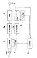
図1は本発明の第1の実施の形態に係る赤外線検出装置のブロック図である。また図2は上記赤外線検出装置の動作を説明するタイミングチャートであり、図4は上記赤外線検出装置のポップコーンノイズ検知部5の要部回路図である。本実施の形態の赤外線検出装置は、焦電素子1と、I/V変換回路2と、第1の電圧増幅部3aと、第2の電圧増幅部3bと、発報部4と、ポップコーンノイズ検知部5と、出力制御回路6、スイッチ回路7及びスイッチ回路8とから構成される。 焦電素子1は、検知エリア内から輻射される赤外線量の変化に応じた電流を出力する。
【0017】
I/V変換回路2は、焦電素子1から出力された検出電流を電圧に変換するものである。電圧に変換された信号は分岐され、一方は第1の電圧増幅部3aに入力され、他方は第2の電圧増幅部3bに入力される。
【0018】
第1の電圧増幅部3aは、I/V変換回路2から入力された信号を増幅して発報部4に入力する。なお、第1の電圧増幅部3aは、人体の移動のスピードに応じた1Hz付近の成分を通過させる帯域通過フィルタの特性を有している。
【0019】
発報部4は、第1の電圧増幅部3aから出力された信号と予め設定された所定値とをコンパレータにて比較し、第1の電圧増幅部3aから入力された信号が所定値以上の振幅を有している場合、発報信号を出力する。
【0020】
第2の電圧増幅部3bは、第1の電圧増幅部3aより高い周波数を選択してI/V変換回路2の出力を増幅する。焦電素子1において人体等の移動による出力と比較してポップコーンノイズは、はるかに立ち上がりが早い。そこで、第2の電圧増幅部3bは、数十Hz以上の成分を通過させる高帯域通過フィルタの特性を有している。これによりポップコーンノイズを人体の移動による出力と区別できる。ただし、必要以上に高い周波数を有する信号を通過させると、S/N比が悪化し、ポップコーンノイズが雑音に埋もれることになる。そこで、本実施の形態では、数十Hzから数百Hzの成分を通過させる帯域通過フィルタの特性を第2の電圧増幅部3bに与えている。
【0021】
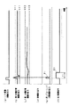
ポップコーンノイズ検知部5は、図2(b)にNout1として示すような第2の電圧増幅部3bの出力が、予め定めた所定値Vh1又はVl1以上の振幅を有している場合、制御回路6に対して図2(c)に示すようなポップコーンノイズ検出信号P3を出力する。
【0022】
ここで、ポップコーンノイズ検知部5は図4に示すように2つのコンパレータにて構成されるウィンドコンパレータであり、第2の電圧増幅部3bから入力された信号SWINが、コンパレータの正負の基準電圧Vh1,Vl1を超えているか否かを判断する。即ち第2の電圧増幅部3bから出力された信号が、予め定められた基準電圧Vh1及びVl1と比較される。ここで、SWIN>Vh1あるいはSWIN<Vl1の時にポップコーンノイズを検知したと判断して、ポップコーンノイズ検知信号を出力する。
【0023】
制御回路6は、ポップコーンノイズ検出信号が入力されると予め定めた時間T1にわたって、スイッチ回路7を通してI/V変換回路2に対し図2(d)に示す出力制御信号Q1を出力するが、このとき同時にスイッチ回路8を通して第2の電圧増幅部3bに対しても、予め定めた時間T2にわたって図2(e)に示す利得抑制信号Q3を出力する。なおポップコーンノイズは、発生するとすぐに減衰し、持続性がない。実際にポップコーンノイズを計測すると、出力のピークレベルは様々であるものの、そのパルス幅は数ms以下であることが分かった。そこで上述したI/V変換回路2の変換インピーダンスを下げるとともに、第2の電圧増幅部3bの利得を下げるには、出力制御信号Q1や利得抑制信号Q3を出力する時間T1,T2は、数秒程度且つT1<T2に設定するのが好ましい。
【0024】
またスイッチングノイズの大きさは1mV程度であり、ポップコーンノイズの大きさ0.1mV〜0.2Vにくらべかなり小さい。そこでスイッチ回路8は、出力制御回路6から利得抑制信号が出力されている間は、第2の電圧増幅部3bの利得を下げる。これにより、スイッチ回路8がオフするときI/V変換回路2において生じるスイッチングノイズの信号レベルは、図2(b)にNout2として示す第2の電圧増幅部3bの出力のように下げられる。
【0025】
従って、この第2の電圧増幅部3bからの出力がポップコーンノイズ検知部5において所定の値Vh1又はVl1を超えないため、ポップコーンノイズ検出信号はポップコーンノイズ検知部5からは出力せずに、再びスイッチ回路7がオンすることはない。但し、この時第2の電圧増幅部3bの利得はゼロにはならず、スイッチングノイズをポップコーンノイズ検出信号として出力しない程度に下げられる。それゆえに、利得抑制信号が出力されている間T2でもあっても図2(b)に示すNout3のような振幅の大きなポップコーンノイズが、焦電素子1において発生した場合でも図2(c)にP4として示すように、ポップコーンノイズ検知部5が、これを検出することが可能となる。つまり、I/V変換回路2の出力制御の状態においても振幅の大きなポップコーンノイズに対しては、その除去が可能となるので、焦電素子1からのポップコーンノイズを以って検出対象を検出したとして、発報信号を出力してしまう所謂誤報を防ぐことができる。
[第2の実施の形態]
図3は本発明の第2の実施の形態に係る赤外線検出装置のブロック図である。また図5は赤外線検出装置のポップコーンノイズ検知部の動作説明図であり、図6は赤外線検出装置の動作を説明するタイミングチャートである。
【0026】
本実施の形態の赤外線検出装置は、焦電素子1と、I/V変換回路2と、第1の電圧増幅部3aと、第2の電圧増幅部3bと、発報部4と、ポップコーンノイズ検知部5と、出力制御回路6、スイッチ回路7及びスイッチ回路9とから構成される。なお、本実施の形態の赤外線検出装置の基本構成は、第1の実施の形態とよく似ており、同じ部分については同一の番号を付してその詳細な説明を省略する。
【0027】
出力制御回路6はポップコーンノイズ検出信号P1が入力されると、図6(d)に示すように予め定めた時間T1にわたり、スイッチ回路7を通してI/V変換回路2に対して出力制御信号Q1を出力するが、このとき同時にスイッチ回路9を通してポップコーンノイズ検知部5に対しても、図6(e)に示すように予め定めた時間T3にわたり、検知レベル抑制信号Q4を出力する。
【0028】
ポップコーンノイズ検知部5は、出力制御回路6から検知レベル抑制信号Q4が出力されている間、ポップコーンノイズ検知レベルを下げ、ポップコーンノイズ検知信号を出しにくくする。具体的には、図5に示すように基準電圧Vh1をより高い方向Vh2へシフトするか、あるいは、基準電圧Vl1をより低い方向Vl2へシフトする。これにより図6(b)に示すように,この第2の電圧増幅部3bからの出力がポップコーンノイズ検知部5において所定の値Vh2又はVl2を越えないため、ポップコーンノイズ検出信号はポップコーンノイズ検知部5から出力されない。
【0029】
なお、前述したようにポップコーンノイズは、実際に計測するとそのパルス幅は数ms以下であるので、前記I/V変換回路2の変換インピーダンスを下げるとともに、ポップコーンノイズ検知部5の検知レベルを下げるには、出力制御信号Q1や検知レベル抑制信号Q4を出力する時間T1,T2は、数秒程度且つT1<T2に設定するのが好ましい。
【0030】
また本発明においてスイッチ回路7のFETは、N型のMOS−FETを使用しているが、一般的にはP型のMOS−FETを用いる場合も十分考えられる。その際スイッチは、制御信号がLowからHighに成った時にオフすることになりその際生じるノイズの向きは負となる。従って、I/V変換回路2で生じるスイッチングノイズの向きは、スイッチ回路7の回路構成が、決まれば一意に決まることになり、ポップコーンノイズ検知部5において、ポップコーンノイズ検知レベルを下げる場合は、基準電圧Vh1とVl1の両方をシフトさせる必要はなく、どちらか一方をシフトさせればよいことになる。ここで、検知レベルを下げているということは、当然ポップコーンノイズも検出しにくくなっており本来なら好ましい状態とは言えないが、基準電圧の一方はシフトする必要がないということは、その方向の感度は下がらないことになり、その方向のポップコーンノイズに対しては全く感度が、下がることがないと言う効果を生む
又、検知レベル抑制信号Q4が第2の電圧増幅部3bの出力のような信号経路に影響を与えれば、この影響はすぐさまポップコーンノイズによるものと同等に扱われるので、その信号の大きさや周波数など注意が必要となる。しかし、この検知レベル抑制信号Q4は、図4に示すようにコンパレーターのウィンドウ基準電圧端子に入力され、第2の電圧増幅部3bの出力が入力される端子とは別になるので、両者の信号の干渉はほとんど無視できることになる。つまり直接ポップコーンノイズ信号経路に影響を与えることなく、検知レベルを下げることが可能となる。
【0031】
【発明の効果】
以上説明したように、請求項1記載の発明にあっては、焦電素子からのポップコーンノイズを以って検出対象を検出したとして、発報信号を出力してしまう所謂誤報をなくすとともに、検出感度を不必要に長期間低下させてしまうことにより、本来の人体の存在や移動の検知ができなくなる所謂失報を防ぐ、優れた赤外線検出装置を提供するという効果を奏する。
【0032】
請求項2記載の発明にあっては、出力制御の状態においても振幅の大きなポップコーンノイズに対しては、その除去が可能であるので、高い信頼性で誤動作を防ぐことができるという効果を奏する。
【0033】
請求項3記載の発明にあっては、ポップコーンノイズ検出の信号経路に直接影響を与えずに検知レベルを変えることができ且つ、一方向のポプコンノイズに対しては全く感度が、下がることがなく高い信頼性で誤動作を防ぐことができるという効果を奏する。
【図面の簡単な説明】
【図1】本発明の第1の実施の形態に係る赤外線検出装置を示すブロック図である。
【図2】上記赤外線検出装置の動作を説明するタイミングチャートである。
【図3】本発明の第2の実施の形態に係る赤外線検出装置を示すブロック図である。
【図4】上記赤外線検出装置のポップコーンノイズ検知部の要部回路図である。
【図5】上記赤外線検出装置のポップコーンノイズ検知部の動作説明である。
【図6】上記赤外線検出装置の動作を説明するタイミングチャートである。
【図7】従来の赤外線検出装置を示すブロック図である。
【図8】上記赤外線検出装置の正常な発報時における動作を説明するタイミングチャートである。
【図9】上記赤外線検出装置のポップコーンノイズ検出時における動作を説明するタイミングチャートである。
【図10】上記赤外線検出装置の動作を説明するタイミングチャートである。
【図11】上記赤外線検出装置のI/V変換回路及びスイッチ回路を示す回路図である。
【符号の説明】
1 焦電素子
2 I/V変換回路
3a 第1の電圧増幅部
3b 第2の電圧増幅部
4 発報部
5 ポップコーンノイズ検知部
6 出力制御回路
7 I/V変換回路の出力を低下せしめるスイッチ回路
8 第2の電圧増幅部の利得を低下せしめるスイッチ回路
9 ポップコーンノイズ検知部の検知レベルを低下せしめるスイッチ回路[0001]
BACKGROUND OF THE INVENTION
The present invention relates to an infrared detection device that detects infrared energy radiated from a human body and detects the presence and movement of the human body.
[0002]
[Prior art]
FIG. 7 is a block diagram of a conventional infrared detection device. As the infrared detection unit, the
[0003]
The frequency characteristic in the infrared detection device is set in accordance with the movement of the human body, and a band pass filter centered around 1 Hz is added to the first
[0004]
However, the
[0005]
Therefore, in the past, a second frequency for amplifying the output of the I /
[0006]
On the other hand, in the popcorn
[0007]
In the switch circuit 7, while the output control signal is output from the
[0008]
[Problems to be solved by the invention]
However, switching noise may occur at the output of the I /
[0009]
Therefore, when the output control signal from the
[0010]
Since this switching noise is a high-frequency signal, the first voltage amplification unit has the characteristics of a low-pass filter, so that even if it is largely removed and input to the reporting unit 4 , a predetermined predetermined value is obtained. Since the value is not exceeded, no detection signal is output to the outside. However, since the second voltage amplifying unit has the characteristics of a high-pass filter, this switching noise, that is, Ns shown in FIG. 10A is reduced by the second
[0011]
The present invention has been made to solve the above-described problems, and the object of the present invention is to output a notification signal on the assumption that a detection target is detected by popcorn noise from a pyroelectric element. The present invention provides an excellent infrared detection device that eliminates so-called false alarms and prevents the so-called false alarms that make it impossible to detect the presence or movement of the original human body by reducing detection sensitivity unnecessarily for a long period of time. There is.
[0012]
[Means for Solving the Problems]
The invention according to
[0013]
According to a second aspect of the present invention, in the infrared detecting device according to the first aspect, once the pop-up noise is detected by the second voltage amplification section, the sensitivity for detecting the pop-corn noise is lowered for a certain time thereafter. It is what.
[0014]
According to a third aspect of the present invention, in the infrared detecting device according to the first aspect, once the popcorn noise detecting unit detects the popcorn noise, the detection level for detecting the popcorn noise is lowered for a certain time thereafter. To do.
[0015]
DETAILED DESCRIPTION OF THE INVENTION
Hereinafter, a first embodiment of an infrared detection apparatus according to the present invention will be described in detail with reference to FIGS. 1, 2, and 4 and a second embodiment based on FIGS. 3, 5, and 6, respectively. To do.
[0016]
[First Embodiment]
FIG. 1 is a block diagram of an infrared detection apparatus according to the first embodiment of the present invention. FIG. 2 is a timing chart for explaining the operation of the infrared detection device, and FIG. 4 is a circuit diagram of a main part of the popcorn
[0017]
The I /
[0018]
The first
[0019]
The reporting unit 4 compares the signal output from the first
[0020]
The second
[0021]
When the output of the second
[0022]
Here, the popcorn
[0023]
When the popcorn noise detection signal is input, the
[0024]
The magnitude of switching noise is about 1 mV, which is much smaller than the magnitude of popcorn noise of 0.1 mV to 0.2 V. Therefore, the
[0025]
Accordingly, since the output from the second
[Second Embodiment]
FIG. 3 is a block diagram of an infrared detecting device according to the second embodiment of the present invention. FIG. 5 is an operation explanatory diagram of the popcorn noise detection unit of the infrared detection device, and FIG. 6 is a timing chart illustrating the operation of the infrared detection device.
[0026]
The infrared detection device of the present embodiment includes a
[0027]
When the popcorn noise detection signal P1 is input, the
[0028]
While the detection level suppression signal Q4 is output from the
[0029]
As described above, when the popcorn noise is actually measured, its pulse width is several ms or less, so that the conversion impedance of the I /
[0030]
Further, in the present invention, the FET of the switch circuit 7 uses an N-type MOS-FET, but generally a P-type MOS-FET is sufficiently conceivable. At that time, the switch is turned off when the control signal changes from Low to High, and the direction of noise generated at that time is negative. Therefore, the direction of the switching noise generated in the I /
[0031]
【The invention's effect】
As described above, according to the first aspect of the present invention, it is possible to eliminate the so-called false alarm that outputs the alarm signal when the detection target is detected by the popcorn noise from the pyroelectric element. By reducing the sensitivity unnecessarily for a long period of time, it is possible to provide an excellent infrared detection device that prevents so-called misreporting that makes it impossible to detect the presence or movement of the original human body .
[0032]
According to the second aspect of the present invention, since popcorn noise having a large amplitude can be removed even in the output control state, it is possible to prevent malfunction with high reliability.
[0033]
In the invention described in
[Brief description of the drawings]
FIG. 1 is a block diagram showing an infrared detection apparatus according to a first embodiment of the present invention.
FIG. 2 is a timing chart for explaining the operation of the infrared detection apparatus.
FIG. 3 is a block diagram showing an infrared detection apparatus according to a second embodiment of the present invention.
FIG. 4 is a main part circuit diagram of a popcorn noise detection unit of the infrared detection device.
FIG. 5 is an operation explanation of a popcorn noise detection unit of the infrared detection device.
FIG. 6 is a timing chart for explaining the operation of the infrared detection device.
FIG. 7 is a block diagram showing a conventional infrared detection device.
FIG. 8 is a timing chart for explaining the operation of the infrared detection device at the time of normal notification.
FIG. 9 is a timing chart for explaining the operation of the infrared detector when popcorn noise is detected.
FIG. 10 is a timing chart for explaining the operation of the infrared detection apparatus.
FIG. 11 is a circuit diagram showing an I / V conversion circuit and a switch circuit of the infrared detection device.
[Explanation of symbols]
DESCRIPTION OF
Claims (3)
Priority Applications (11)
| Application Number | Priority Date | Filing Date | Title |
|---|---|---|---|
| JP21404298A JP3829484B2 (en) | 1998-07-29 | 1998-07-29 | Infrared detector |
| DE69943177T DE69943177D1 (en) | 1998-02-27 | 1999-02-24 | Infrared radiation detector |
| EP99103529A EP0939311B1 (en) | 1998-02-27 | 1999-02-24 | Infrared-rays detector |
| SG1999001523A SG73625A1 (en) | 1998-02-27 | 1999-02-25 | Infrared-rays detector |
| US09/257,509 US6313462B1 (en) | 1998-02-27 | 1999-02-25 | Infrared-rays detector |
| CNB2005100650903A CN100422700C (en) | 1998-02-27 | 1999-02-26 | Infrared ray detecting apparatus |
| CNB991025733A CN1277108C (en) | 1998-02-27 | 1999-02-26 | Infrared-rays detector |
| TW88102993A TW417073B (en) | 1998-06-26 | 1999-02-26 | Infrared-rays detector |
| CNB2005100651681A CN100422701C (en) | 1998-02-27 | 1999-02-26 | Infrared ray detecting apparatus |
| KR10-1999-0006619A KR100376724B1 (en) | 1998-02-27 | 1999-02-27 | Infrared-rays detector |
| HK00100059.8A HK1021023A1 (en) | 1998-02-27 | 2000-01-05 | Infrared-rays detector |
Applications Claiming Priority (1)
| Application Number | Priority Date | Filing Date | Title |
|---|---|---|---|
| JP21404298A JP3829484B2 (en) | 1998-07-29 | 1998-07-29 | Infrared detector |
Publications (2)
| Publication Number | Publication Date |
|---|---|
| JP2000046960A JP2000046960A (en) | 2000-02-18 |
| JP3829484B2 true JP3829484B2 (en) | 2006-10-04 |
Family
ID=16649321
Family Applications (1)
| Application Number | Title | Priority Date | Filing Date |
|---|---|---|---|
| JP21404298A Expired - Fee Related JP3829484B2 (en) | 1998-02-27 | 1998-07-29 | Infrared detector |
Country Status (1)
| Country | Link |
|---|---|
| JP (1) | JP3829484B2 (en) |
Families Citing this family (2)
| Publication number | Priority date | Publication date | Assignee | Title |
|---|---|---|---|---|
| JP2002071832A (en) * | 2000-08-28 | 2002-03-12 | Matsushita Electric Works Ltd | Infrared detecting device |
| JP4329491B2 (en) * | 2003-10-28 | 2009-09-09 | パナソニック電工株式会社 | Infrared detector |
-
1998
- 1998-07-29 JP JP21404298A patent/JP3829484B2/en not_active Expired - Fee Related
Also Published As
| Publication number | Publication date |
|---|---|
| JP2000046960A (en) | 2000-02-18 |
Similar Documents
| Publication | Publication Date | Title |
|---|---|---|
| US8723532B2 (en) | Capacitive proximity device and electronic device comprising the capacitive proximity device | |
| RU2276329C2 (en) | Circuit for measuring signal | |
| US6313462B1 (en) | Infrared-rays detector | |
| JP3947865B2 (en) | Preamplifier | |
| JP3829484B2 (en) | Infrared detector | |
| US20040189149A1 (en) | Transconductance circuit for piezoelectric transducer | |
| JP3385971B2 (en) | Infrared detector | |
| JP3829483B2 (en) | Infrared detector | |
| US5352895A (en) | Pyroelectric device | |
| US5444431A (en) | Intrusion monitoring device | |
| JPH10300571A (en) | Current-to-voltage conversion circuit in pyroelectric infrared detecting apparatus | |
| KR100516529B1 (en) | Electronic radiation trapping circuit device | |
| JP3458735B2 (en) | Infrared detector | |
| JP3654154B2 (en) | Infrared human body detector | |
| JP2690043B2 (en) | Infrared detector | |
| JP2001289951A (en) | Distance measuring device | |
| JP3046977B2 (en) | Signal current detection circuit | |
| JP3446619B2 (en) | Infrared detector | |
| JP2597482Y2 (en) | Photoelectric switch | |
| JPH11248532A (en) | Infrared ray detecting apparatus | |
| NL1018226C1 (en) | Thermocouple circuit with open circuit detection facility, uses high frequency signals to check continuity, which do not interfere with correct operation of thermocouple | |
| JP2002071832A (en) | Infrared detecting device | |
| JPH02218983A (en) | Ultrasonic sensor | |
| JPH05299999A (en) | Light receiving circuit | |
| JP2001183231A (en) | Infrared ray detecting device |
Legal Events
| Date | Code | Title | Description |
|---|---|---|---|
| A621 | Written request for application examination |
Free format text: JAPANESE INTERMEDIATE CODE: A621 Effective date: 20050216 |
|
| A977 | Report on retrieval |
Free format text: JAPANESE INTERMEDIATE CODE: A971007 Effective date: 20060612 |
|
| TRDD | Decision of grant or rejection written | ||
| A01 | Written decision to grant a patent or to grant a registration (utility model) |
Free format text: JAPANESE INTERMEDIATE CODE: A01 Effective date: 20060620 |
|
| A61 | First payment of annual fees (during grant procedure) |
Free format text: JAPANESE INTERMEDIATE CODE: A61 Effective date: 20060703 |
|
| FPAY | Renewal fee payment (event date is renewal date of database) |
Free format text: PAYMENT UNTIL: 20090721 Year of fee payment: 3 |
|
| S533 | Written request for registration of change of name |
Free format text: JAPANESE INTERMEDIATE CODE: R313533 |
|
| FPAY | Renewal fee payment (event date is renewal date of database) |
Free format text: PAYMENT UNTIL: 20090721 Year of fee payment: 3 |
|
| R350 | Written notification of registration of transfer |
Free format text: JAPANESE INTERMEDIATE CODE: R350 |
|
| FPAY | Renewal fee payment (event date is renewal date of database) |
Free format text: PAYMENT UNTIL: 20090721 Year of fee payment: 3 |
|
| FPAY | Renewal fee payment (event date is renewal date of database) |
Free format text: PAYMENT UNTIL: 20100721 Year of fee payment: 4 |
|
| FPAY | Renewal fee payment (event date is renewal date of database) |
Free format text: PAYMENT UNTIL: 20100721 Year of fee payment: 4 |
|
| FPAY | Renewal fee payment (event date is renewal date of database) |
Free format text: PAYMENT UNTIL: 20110721 Year of fee payment: 5 |
|
| FPAY | Renewal fee payment (event date is renewal date of database) |
Free format text: PAYMENT UNTIL: 20120721 Year of fee payment: 6 |
|
| FPAY | Renewal fee payment (event date is renewal date of database) |
Free format text: PAYMENT UNTIL: 20120721 Year of fee payment: 6 |
|
| FPAY | Renewal fee payment (event date is renewal date of database) |
Free format text: PAYMENT UNTIL: 20130721 Year of fee payment: 7 |
|
| LAPS | Cancellation because of no payment of annual fees |