JP3829398B2 - Battery manufacturing method - Google Patents
Battery manufacturing method Download PDFInfo
- Publication number
- JP3829398B2 JP3829398B2 JP07795897A JP7795897A JP3829398B2 JP 3829398 B2 JP3829398 B2 JP 3829398B2 JP 07795897 A JP07795897 A JP 07795897A JP 7795897 A JP7795897 A JP 7795897A JP 3829398 B2 JP3829398 B2 JP 3829398B2
- Authority
- JP
- Japan
- Prior art keywords
- electrode
- separator
- bonded
- positive
- electrodes
- Prior art date
- Legal status (The legal status is an assumption and is not a legal conclusion. Google has not performed a legal analysis and makes no representation as to the accuracy of the status listed.)
- Expired - Fee Related
Links
Images

Classifications
-
- Y—GENERAL TAGGING OF NEW TECHNOLOGICAL DEVELOPMENTS; GENERAL TAGGING OF CROSS-SECTIONAL TECHNOLOGIES SPANNING OVER SEVERAL SECTIONS OF THE IPC; TECHNICAL SUBJECTS COVERED BY FORMER USPC CROSS-REFERENCE ART COLLECTIONS [XRACs] AND DIGESTS
- Y02—TECHNOLOGIES OR APPLICATIONS FOR MITIGATION OR ADAPTATION AGAINST CLIMATE CHANGE
- Y02E—REDUCTION OF GREENHOUSE GAS [GHG] EMISSIONS, RELATED TO ENERGY GENERATION, TRANSMISSION OR DISTRIBUTION
- Y02E60/00—Enabling technologies; Technologies with a potential or indirect contribution to GHG emissions mitigation
- Y02E60/10—Energy storage using batteries
-
- Y—GENERAL TAGGING OF NEW TECHNOLOGICAL DEVELOPMENTS; GENERAL TAGGING OF CROSS-SECTIONAL TECHNOLOGIES SPANNING OVER SEVERAL SECTIONS OF THE IPC; TECHNICAL SUBJECTS COVERED BY FORMER USPC CROSS-REFERENCE ART COLLECTIONS [XRACs] AND DIGESTS
- Y02—TECHNOLOGIES OR APPLICATIONS FOR MITIGATION OR ADAPTATION AGAINST CLIMATE CHANGE
- Y02P—CLIMATE CHANGE MITIGATION TECHNOLOGIES IN THE PRODUCTION OR PROCESSING OF GOODS
- Y02P70/00—Climate change mitigation technologies in the production process for final industrial or consumer products
- Y02P70/50—Manufacturing or production processes characterised by the final manufactured product
Landscapes
- Secondary Cells (AREA)
- Primary Cells (AREA)
Description
【0001】
【発明の属する技術分野】
本発明は、一方又は双方にセパレータが固着された正負の電極を交互に積層または巻回することにより発電要素を形成する電池の製造方法に関する。
【0002】
【従来の技術】
電池(活物質保持形の化学電池であり一次電池と二次電池を含む)は、一般に正負の電極をセパレータを積層または巻回することにより発電要素を形成する。セパレータは、これら正負の電極を分離するための絶縁体であり、電解液を含浸できるものを使用する。例えば、巻回型の円筒型電池は、1枚ずつの帯状の正負の電極を2枚の帯状のセパレータを介して巻回することにより発電要素を形成し、この発電要素を円筒型の電池容器に収納する。また、積層型の角型電池は、複数枚ずつの薄板状の正負の電極を複数枚のシート状のセパレータを介して積層することにより発電要素を形成し、この発電要素を角型の電池容器に収納する。
【0003】
【発明が解決しようとする課題】
ところが、従来の電池の製造方法では、電極とセパレータを単に重ね合わせた状態で巻回したり積層していたので、電極とセパレータとの間が密着せずに部分的に浮き上がって電極間距離が変化したり、これら電極やセパレータの重なりがずれるのを防止するために、発電要素を巻回や積層した状態で一旦テープ等で止め付けた後に金属缶等からなる堅牢な電池容器に収納して圧迫しなければならず、テープ止め等の作業が面倒になるだけでなく、肉厚が厚く重くて高価な電池容器を用いなければならないという問題が生じていた。
【0004】
本発明は、かかる事情に鑑みてなされたものであり、一方又は双方にセパレータが固着された正負の電極をさらに接着することにより、この発電要素の製造を容易にすると共に、柔軟なシート状の電池容器等に収納することが可能となる電池を提供することを目的としている。
【0005】
【課題を解決するための手段】
即ち、本発明は、上記課題を解決するために、請求項1に記載の発明は、少なくともいずれか一方の電極にセパレータが接着された正負の電極を1枚ずつ以上交互に、少なくともいずれか一方の電極に接着されたセパレータを介して巻回することにより発電要素を形成する電池の製造方法において、正負の電極を1枚ずつ以上交互に、少なくともいずれか一方の電極に接着されたセパレータを介して間隔を開けて配置する電極配置工程と、これら間隔を開けて配置された正負極の、セパレータが接着された電極とセパレータが接着されていない電極の少なくとも一方の対向面、又は共にセパレータが接着された正極と負極の少なくとも一方の対向面に、接着剤を塗布する接着剤塗布工程と、これら間隔を開けて配置された正負極の、セパレータが接着された電極とセパレータが接着されていない電極の対向面、又は共にセパレータが接着された正極と負極の対向面を、密着させて接着し発電要素を形成する電極接着工程とを備えたことを特徴とする。
【0006】
請求項1に記載の発明の手段によれば、正負の電極がいずれか一方又は双方の電極に接着されたセパレータを介して接着により接着されるので、巻回型の発電要素を一体化することができる。従って、この発電要素を巻回した状態でテープ等で止め付けたり電池缶等に収納して圧迫しなくても、電極間距離が変化したり電極やセパレータの重なりがずれて電池特性が損なわれるようなことがなくなり、発電要素の製造が容易になるだけでなく、電池容器の材質や形状等を限定されることもなくなる。しかも、正負の電極に効率よく接着剤を塗布し密着させて接着することができるので、生産性を高めることができる。
【0007】
なお、セパレータを接着した電極は、例えば長尺な電極とセパレータに順次接着剤を塗布し、これらをロールプレスで押圧して連続的に接着すると共に、これを所定形状ごとに打ち抜き成形することにより、一括して効率よく製造することができる。
【0008】
また、請求項2に記載の発明は、少なくともいずれか一方の電極にセパレータが接着された正負の電極を1枚ずつ以上交互に、少なくともいずれか一方の電極に接着されたセパレータを介して積層または巻回することにより発電要素を形成する電池の製造方法において、正負の電極を1枚ずつ以上交互に、少なくともいずれか一方の電極に接着されたセパレータを介して、正負の電極の間隔距離を対向面の一端側が他端側よりも広くなるように配置する電極配置工程と、これら間隔を開けて配置された正負極の、セパレータが接着された電極とセパレータが接着されていない電極の少なくとも一方の対向面、又は共にセパレータが接着された正極と負極の少なくとも一方の対向面に、接着剤を塗布する接着剤塗布工程と、これら間隔を開けて配置された正負極の、セパレータが接着された電極とセパレータが接着されていない電極の対向面、又は共にセパレータが接着された正極と負極の対向面を、密着させて接着し発電要素を形成する電極接着工程とを備えたことを特徴とする。
【0009】
請求項2に記載の発明の手段によれば、請求項1の効果に加えて、正負の電極の間隔が一端側で広がるので、この一端側から接着剤を噴霧すること等により容易に塗布することができるようになる。なお、この発明は、巻回型に限らず、積層型の発電要素にも適用される。
【0010】
さらに、前記接着剤塗布工程を、間隔を開けて配置された正負の電極の対向面又はこの電極に接着されたセパレータの対向面間に両面接着シートを挿入する接着シート挿入工程としてもよい。
【0011】
この手段によれば、接着剤の塗布に代えて、シート状の接着剤からなる両面接着シート又はシートの両面に接着層を形成した両面接着シートを挿入することにより、正負の電極を接着することができる。
【0012】
さらに、前記電極接着工程で形成された発電要素をバリア性のシート状の電池容器内に収納する発電要素収納工程を備えてもよい。
【0013】
この手段によれば、発電要素が一体化されるので、この発電要素を柔軟なシート状の電池容器内に収納しても、電極間距離が変化したり電極やセパレータの重なりがずれるようなおそれがなくなり、この電池容器を肉厚が薄く軽量で安価なものとすることができる。
【0014】
【発明の実施の形態】
以下、本発明の実施形態について図面を参照して説明する。
【0015】
図1〜図4は本発明の一実施形態を示すものであって、図1は非水電解質二次電池の発電要素の製造過程を示す縦断面図、図2は非水電解質二次電池の発電要素の構成を示す縦断面図、図2は一体化した発電要素の構造を示す縦断面図、図4は発電要素をアルミラミネートシートで封口した非水電解質二次電池の斜視図である。
【0016】
本実施形態は、図4に示すように、積層型の発電要素1をアルミラミネートシート2で覆って封口した非水電解質二次電池の製造方法について説明する。この発電要素1は、図2に示すように、複数枚ずつの正極11と負極12とセパレータ13とからなる。正極11は、正極集電板にリチウムコバルト複合酸化物等の正極活物質を塗布した方形の薄板状である。負極12は、負極集電板にグラファイト等の負極活物質を塗布した方形の薄板状である。セパレータ13は、微多孔性樹脂フィルム等の方形のシートである。そして、各負極12の両面には、予めこの負極12と同サイズのセパレータ13がそれぞれ接着されている。このようにセパレータ13を接着した負極12は、例えば長尺な帯状の負極とセパレータに順次PVDF等の接着剤を塗布し張り合わせてロールプレスで押圧し連続的に接着し乾燥させると共に、これを図2に示したような所定形状ごとに打ち抜き成形することにより、一括して効率よく製造することができる。正極11は、本実施形態の非水電解質二次電池では、必ず負極12と対向していなければならないので、長尺な帯状のものを負極12よりも少し小さいサイズに打ち抜き成形しておく。
【0017】
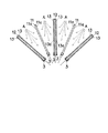
上記正極11とセパレータ13を接着した負極12は、1枚ずつ交互に配置される(電極配置工程)。また、非水電解質二次電池では正極11が必ず負極12と対向しなければならないことから、左右の端にはそれぞれセパレータ13を接着した負極12を配置する。そして、図1に示すように、これらの電極11,12の下部を支持体3でそれぞれ支持し、これらの支持体3を下方を中心に扇を開くようにそれぞれ揺動させる。すると、正極11の対向面11aと負極12に接着されたセパレータ13の対向面13aとの間隔距離が上方ほど広くなる。
【0018】
このようにして電極11,12が扇状に広がると、これらの電極11,12間に上方からそれぞれPVDF等の接着剤Aを噴霧することにより、正極11の各対向面11aと負極12に接着されたセパレータ13の各対向面13aにこの接着剤Aを塗布する(接着剤塗布工程)。この際、接着剤Aは、噴霧以外の方法で塗布してもよく、また、電極11,12間のいずれか一方の対向面11a又は対向面13aにのみ塗布するようにしてもよい。なお、この接着剤Aの塗布に代えて、正極11の対向面11aと負極12に接着されたセパレータ13の対向面13aとの間に、それぞれ両面接着シートを挿入することもできる(接着シート挿入工程)。両面接着シートは、接着剤をシート状に形成したものか、薄い樹脂又は紙等のシート材の両面に接着剤の層を形成したものである。また、これらの接着剤(接着剤A)や両面接着シートは、電解液に対して安定であり、この電解液を含浸したり流通させ得るものでなければならない。
【0019】
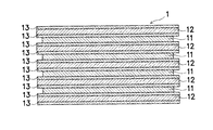
接着剤Aの塗布等が完了すると、支持体3を扇が閉じるようにそれぞれ移動させることにより、正極11の対向面11aと負極12に接着されたセパレータ13の対向面13aとを密着させて接着する(電極接着工程)。そして、これら密着させた電極11,12を両側から圧迫しながら80°Cの雰囲気中で乾燥させると、各対向面11a,13a間が接着されて、図3に示すような積層型の発電要素1が形成される。
【0020】
上記発電要素1は、図4に示したように、バリア性を有するアルミラミネートシート2で覆い、内部に非水電解液を充填して周囲を封口することにより非水電解質二次電池を形成する(発電要素収納工程)。この際、発電要素1の各正極11と各負極12にそれぞれ接続されるリード4は、アルミラミネートシート2を重ね合わせた間から先端部を突出させた状態で確実に封口する。このようにして形成された非水電解質二次電池は、例えばカード型の外装ケース内に収納してカード型二次電池として使用することができる。なお、図1〜図3に示した正極11と負極12とセパレータ13の厚さは、発電要素1の構成を分かり易くするために、実際よりも厚く描いて示している。
【0021】
上記構成の非水電解質二次電池は、セパレータ13を接着した負極12に正極11がさらに接着されて積層型の発電要素1が一体化されるので、この発電要素1をテープ等で止め付けたり電池缶等に収納して圧迫する必要がなくなる。従って、発電要素1の製造が容易となるだけでなく、この発電要素1をそのままアルミラミネートシート2のような柔軟な電池容器に収納しても、正極11と負極12との間隔距離が変化したり、これら正極11と負極12とセパレータ13の重なりがずれるようなおそれがなくなる。しかも、複数枚の正極11と負極12に一括して接着剤Aの塗布等を行いまとめて接着することができるので、発電要素1の生産性を高めることができる。
【0022】
なお、上記実施形態では、セパレータ13を接着した負極12の全面に正極11を接着する場合について説明したが、これらを部分的に接着することもできる。しかも、この場合には、接着剤(接着剤A)や両面接着シートが電解液を含浸できないものであってもよい。
【0023】
また、上記実施形態では、セパレータ13を予め負極12に固着した場合について説明したが、絶縁が確実に行えるのであれば、このセパレータ13を正極11に接着しておいたり、正負の電極11,12の片側の面にそれぞれ接着しておくこともできる。
【0024】
さらに、上記実施形態では、各電極11,12を扇状に広げて接着剤Aの塗布等を行う場合について説明したが、これらの対向面11a,13aの間隔が十分に広ければ、各電極11,12が平行なまま接着剤Aの塗布等を行うこともできる。
【0025】
さらに、上記実施形態では、非水電解質二次電池について説明したが、本発明は、これに限らず一次電池や他の二次電池にも同様に実施することができる。ただし、充電時にガスを発生する二次電池の場合には、このガスの発生に対応する方策を講じる必要がある。さらに、正極11と負極12とセパレータ13の構成も、これら電池の種類等に応じて任意に変更することができる。
【0026】
さらに、上記実施形態では、積層型の発電要素1について説明したが、巻回型等の他の構造の発電要素にも同様に実施することができる。巻回型の場合には、帯状の正負の電極11,12を巻回する直前に接着剤Aの塗布等を行い、テンションを加えて巻回することにより圧迫して接着することができる。
【0027】
【発明の効果】
以上の説明から明らかなように、本発明の電池の製造方法によれば、正負の電極をセパレータを介して接着により接着して発電要素を一体化することができるので、この発電要素の製造が容易になる。しかも、この発電要素は、電極間距離が変化したり電極やセパレータの重なりがずれるようなおそれがないので、柔軟なシート状の電池容器等に収納することができるようになり、電池の薄肉小型化や軽量化を図りコストダウンに貢献できる。
【図面の簡単な説明】
【図1】 本発明の一実施形態を示すものであって、非水電解質二次電池の発電要素の製造過程を示す縦断面図である。
【図2】 本発明の一実施形態を示すものであって、非水電解質二次電池の発電要素の構成を示す縦断面図である。
【図3】 本発明の一実施形態を示すものであって、一体化した発電要素の構造を示す縦断面図である。
【図4】 本発明の一実施形態を示すものであって、発電要素をアルミラミネートシートで封口した非水電解質二次電池の斜視図である。
【符号の説明】
1 発電要素
2 アルミラミネートシート
11 正極
12 負極
13 セパレータ
A 接着剤[0001]
BACKGROUND OF THE INVENTION
The present invention relates to a battery manufacturing method in which a power generating element is formed by alternately laminating or winding positive and negative electrodes each having a separator fixed thereto.
[0002]
[Prior art]
A battery (an active material holding type chemical battery including a primary battery and a secondary battery) generally forms a power generation element by laminating or winding a positive and negative electrode on a separator. The separator is an insulator for separating these positive and negative electrodes, and a separator that can be impregnated with an electrolytic solution is used. For example, a wound-type cylindrical battery forms a power generation element by winding each band-shaped positive and negative electrodes through two band-shaped separators, and this power generation element is formed into a cylindrical battery container. Store in. In addition, a stacked prismatic battery forms a power generation element by stacking a plurality of thin plate-like positive and negative electrodes via a plurality of sheet-like separators, and the power generation element is formed into a square battery container. Store in.
[0003]
[Problems to be solved by the invention]
However, in the conventional battery manufacturing method, the electrode and separator are wound or laminated in a state where they are simply overlapped, so that the distance between the electrodes changes because the electrode and the separator are not in close contact with each other and are lifted up. In order to prevent the electrodes and separators from being overlapped, the power generation element is wound or stacked and once secured with tape, etc., and then stored in a sturdy battery container made of metal cans and pressed. In addition to troublesome work such as tape fastening, there is a problem that a thick and heavy battery container must be used.
[0004]
The present invention has been made in view of such circumstances, and by further adhering positive and negative electrodes having a separator fixed to one or both of them, this power generation element can be easily manufactured and a flexible sheet-like element can be produced. An object of the present invention is to provide a battery that can be stored in a battery container or the like.
[0005]
[Means for Solving the Problems]
That is, in order to solve the above-mentioned problems, the invention according to
[0006]
According to the means of the invention described in
[0007]
In addition, the electrode to which the separator is bonded is formed by, for example, applying an adhesive sequentially to the long electrode and the separator, pressing them with a roll press to continuously bond them, and punching and molding them in predetermined shapes. , Can be manufactured efficiently in a lump.
[0008]
Further, in the invention according to
[0009]
According to the means of the second aspect of the invention, in addition to the effect of the first aspect, the interval between the positive and negative electrodes is widened on one end side, so that it can be easily applied by spraying an adhesive from the one end side. Will be able to. In addition, this invention is applied not only to a winding type but to a laminated type power generation element.
[0010]
Furthermore, the adhesive application step may be an adhesive sheet inserting step in which a double-sided adhesive sheet is inserted between the opposing surfaces of the positive and negative electrodes arranged at intervals or the opposing surfaces of the separator bonded to the electrodes.
[0011]
According to this means, instead of applying an adhesive, a positive and negative electrode is bonded by inserting a double-sided adhesive sheet made of a sheet-like adhesive or a double-sided adhesive sheet having an adhesive layer formed on both sides of the sheet. Can do.
[0012]
Furthermore, you may provide the electric power generation element accommodation process which accommodates the electric power generation element formed by the said electrode adhesion process in a barrier-type sheet-like battery container.
[0013]
According to this means, since the power generation element is integrated, there is a possibility that even if the power generation element is housed in a flexible sheet-like battery container, the distance between the electrodes may change or the electrodes and separators may not overlap. Thus, the battery container can be made thin, lightweight and inexpensive.
[0014]
DETAILED DESCRIPTION OF THE INVENTION
Embodiments of the present invention will be described below with reference to the drawings.
[0015]
1 to 4 show an embodiment of the present invention. FIG. 1 is a longitudinal sectional view showing a manufacturing process of a power generation element of a nonaqueous electrolyte secondary battery, and FIG. 2 is a diagram of the nonaqueous electrolyte secondary battery. FIG. 2 is a longitudinal sectional view showing the structure of an integrated power generation element, and FIG. 4 is a perspective view of a nonaqueous electrolyte secondary battery in which the power generation element is sealed with an aluminum laminate sheet.
[0016]
In the present embodiment, as shown in FIG. 4, a method for manufacturing a nonaqueous electrolyte secondary battery in which a laminated
[0017]
The
[0018]
Thus, when the
[0019]
When the application of the adhesive A and the like is completed, the support 3 is moved so that the fan is closed, thereby bringing the opposing
[0020]
As shown in FIG. 4, the
[0021]
In the non-aqueous electrolyte secondary battery having the above-described configuration, the
[0022]
In addition, although the said embodiment demonstrated the case where the
[0023]
In the above embodiment, the case where the
[0024]
Furthermore, in the above embodiment, the case where the
[0025]
Furthermore, although the said embodiment demonstrated the nonaqueous electrolyte secondary battery, this invention can be similarly implemented not only to this but a primary battery and another secondary battery. However, in the case of a secondary battery that generates gas during charging, it is necessary to take measures to cope with the generation of this gas. Furthermore, the configurations of the
[0026]
Furthermore, in the said embodiment, although the laminated type electric
[0027]
【The invention's effect】
As is apparent from the above description, according to the battery manufacturing method of the present invention, the power generating element can be integrated by bonding the positive and negative electrodes by adhesion via the separator. It becomes easy. In addition, this power generation element can be stored in a flexible sheet-like battery container or the like because there is no possibility that the distance between electrodes changes or the overlap of electrodes and separators shifts. Can contribute to cost reduction by reducing weight and weight.
[Brief description of the drawings]
FIG. 1, showing an embodiment of the present invention, is a longitudinal sectional view showing a manufacturing process of a power generating element of a nonaqueous electrolyte secondary battery.
FIG. 2, showing an embodiment of the present invention, is a longitudinal sectional view showing a configuration of a power generation element of a nonaqueous electrolyte secondary battery.
FIG. 3 is a longitudinal sectional view showing the structure of an integrated power generation element according to an embodiment of the present invention.
FIG. 4 is a perspective view of a non-aqueous electrolyte secondary battery in which an electric power generation element is sealed with an aluminum laminate sheet, showing an embodiment of the present invention.
[Explanation of symbols]
DESCRIPTION OF
Claims (2)
Priority Applications (1)
| Application Number | Priority Date | Filing Date | Title |
|---|---|---|---|
| JP07795897A JP3829398B2 (en) | 1997-03-28 | 1997-03-28 | Battery manufacturing method |
Applications Claiming Priority (1)
| Application Number | Priority Date | Filing Date | Title |
|---|---|---|---|
| JP07795897A JP3829398B2 (en) | 1997-03-28 | 1997-03-28 | Battery manufacturing method |
Publications (2)
| Publication Number | Publication Date |
|---|---|
| JPH10275629A JPH10275629A (en) | 1998-10-13 |
| JP3829398B2 true JP3829398B2 (en) | 2006-10-04 |
Family
ID=13648505
Family Applications (1)
| Application Number | Title | Priority Date | Filing Date |
|---|---|---|---|
| JP07795897A Expired - Fee Related JP3829398B2 (en) | 1997-03-28 | 1997-03-28 | Battery manufacturing method |
Country Status (1)
| Country | Link |
|---|---|
| JP (1) | JP3829398B2 (en) |
Families Citing this family (5)
| Publication number | Priority date | Publication date | Assignee | Title |
|---|---|---|---|---|
| WO1999026307A1 (en) * | 1997-11-19 | 1999-05-27 | Mitsubishi Denki Kabushiki Kaisha | Lithium ion secondary battery and manufacture thereof |
| JP2007280806A (en) * | 2006-04-07 | 2007-10-25 | Nissan Motor Co Ltd | Electrode for battery |
| US20150207178A1 (en) * | 2012-08-27 | 2015-07-23 | Nec Energy Devices, Ltd. | Battery module |
| WO2014126430A1 (en) | 2013-02-15 | 2014-08-21 | 주식회사 엘지화학 | Electrode assembly and polymer secondary battery cell comprising same |
| JP6829974B2 (en) * | 2016-09-29 | 2021-02-17 | 株式会社エンビジョンAescジャパン | Rechargeable battery |
-
1997
- 1997-03-28 JP JP07795897A patent/JP3829398B2/en not_active Expired - Fee Related
Also Published As
| Publication number | Publication date |
|---|---|
| JPH10275629A (en) | 1998-10-13 |
Similar Documents
| Publication | Publication Date | Title |
|---|---|---|
| JP4025930B2 (en) | Battery manufacturing method | |
| US11075374B2 (en) | Method for producing electrode assembly and method for producing nonaqueous electrolyte secondary battery | |
| US8900742B2 (en) | Secondary battery and method of manufacturing the secondary battery | |
| JP6788107B2 (en) | Manufacturing method of electrode unit for battery cell and electrode unit | |
| EP2487747A2 (en) | Electrode assembly for a battery and method for manufacturing same | |
| JP4402134B2 (en) | Multilayer secondary battery and manufacturing method thereof | |
| JP6859059B2 (en) | Lithium-ion secondary battery and its manufacturing method | |
| US20110195298A1 (en) | Stacked secondary battery | |
| JP6775154B2 (en) | Power storage device | |
| JP2004265761A (en) | Film package battery | |
| US10090553B2 (en) | Electrode assembly and method of manufacturing the same | |
| JP7402175B2 (en) | Battery and its manufacturing method | |
| JP7221122B2 (en) | Battery cell electrode assembly manufacturing method and battery cell | |
| JP2000223109A5 (en) | ||
| KR101663351B1 (en) | Cell for electrochemical device and preparation method thereof | |
| JP4359809B2 (en) | Storage element module and manufacturing method thereof | |
| WO1999031751A1 (en) | Lithium ion secondary battery and its manufacture | |
| JP2000200584A (en) | Rectangular battery | |
| JP2000077091A (en) | Battery having spiral electrode body and its manufacture | |
| US10424808B2 (en) | Electrode roll and manufacturing method for electrode roll | |
| JP2002157997A (en) | Method of manufacturing collapsible lithium battery | |
| KR101387137B1 (en) | Electrode assembly and rechargeable battery with the same | |
| JP3829398B2 (en) | Battery manufacturing method | |
| KR102327294B1 (en) | Method and apparatus for applying a self-adhesive film to an electrical energy storage cell | |
| JP2002025514A (en) | Sealed battery |
Legal Events
| Date | Code | Title | Description |
|---|---|---|---|
| A521 | Written amendment |
Free format text: JAPANESE INTERMEDIATE CODE: A523 Effective date: 20040310 |
|
| A621 | Written request for application examination |
Free format text: JAPANESE INTERMEDIATE CODE: A621 Effective date: 20040310 |
|
| A977 | Report on retrieval |
Free format text: JAPANESE INTERMEDIATE CODE: A971007 Effective date: 20050701 |
|
| A131 | Notification of reasons for refusal |
Free format text: JAPANESE INTERMEDIATE CODE: A131 Effective date: 20050927 |
|
| A521 | Written amendment |
Free format text: JAPANESE INTERMEDIATE CODE: A523 Effective date: 20051128 |
|
| A711 | Notification of change in applicant |
Free format text: JAPANESE INTERMEDIATE CODE: A712 Effective date: 20051213 |
|
| RD03 | Notification of appointment of power of attorney |
Free format text: JAPANESE INTERMEDIATE CODE: A7423 Effective date: 20060119 |
|
| TRDD | Decision of grant or rejection written | ||
| A01 | Written decision to grant a patent or to grant a registration (utility model) |
Free format text: JAPANESE INTERMEDIATE CODE: A01 Effective date: 20060620 |
|
| A61 | First payment of annual fees (during grant procedure) |
Free format text: JAPANESE INTERMEDIATE CODE: A61 Effective date: 20060703 |
|
| R150 | Certificate of patent or registration of utility model |
Free format text: JAPANESE INTERMEDIATE CODE: R150 |
|
| LAPS | Cancellation because of no payment of annual fees |