JP3827169B2 - Method for fastening a plurality of members - Google Patents
Method for fastening a plurality of members Download PDFInfo
- Publication number
- JP3827169B2 JP3827169B2 JP01447196A JP1447196A JP3827169B2 JP 3827169 B2 JP3827169 B2 JP 3827169B2 JP 01447196 A JP01447196 A JP 01447196A JP 1447196 A JP1447196 A JP 1447196A JP 3827169 B2 JP3827169 B2 JP 3827169B2
- Authority
- JP
- Japan
- Prior art keywords
- head
- rivet
- blind
- hole
- sheet
- Prior art date
- Legal status (The legal status is an assumption and is not a legal conclusion. Google has not performed a legal analysis and makes no representation as to the accuracy of the status listed.)
- Expired - Fee Related
Links
- 238000000034 method Methods 0.000 title claims abstract description 42
- 230000015572 biosynthetic process Effects 0.000 claims description 3
- 238000013459 approach Methods 0.000 claims 1
- 230000007423 decrease Effects 0.000 claims 1
- 230000006835 compression Effects 0.000 abstract description 5
- 238000007906 compression Methods 0.000 abstract description 5
- 238000004519 manufacturing process Methods 0.000 abstract description 3
- 239000002184 metal Substances 0.000 abstract description 3
- 238000005520 cutting process Methods 0.000 description 4
- 229910000831 Steel Inorganic materials 0.000 description 3
- 239000010959 steel Substances 0.000 description 3
- 238000003780 insertion Methods 0.000 description 2
- 230000037431 insertion Effects 0.000 description 2
- 238000005096 rolling process Methods 0.000 description 2
- 241000167854 Bourreria succulenta Species 0.000 description 1
- 238000002788 crimping Methods 0.000 description 1
- 238000005553 drilling Methods 0.000 description 1
- 239000012530 fluid Substances 0.000 description 1
- 238000004080 punching Methods 0.000 description 1
Images


Classifications
-
- F—MECHANICAL ENGINEERING; LIGHTING; HEATING; WEAPONS; BLASTING
- F16—ENGINEERING ELEMENTS AND UNITS; GENERAL MEASURES FOR PRODUCING AND MAINTAINING EFFECTIVE FUNCTIONING OF MACHINES OR INSTALLATIONS; THERMAL INSULATION IN GENERAL
- F16B—DEVICES FOR FASTENING OR SECURING CONSTRUCTIONAL ELEMENTS OR MACHINE PARTS TOGETHER, e.g. NAILS, BOLTS, CIRCLIPS, CLAMPS, CLIPS OR WEDGES; JOINTS OR JOINTING
- F16B19/00—Bolts without screw-thread; Pins, including deformable elements; Rivets
- F16B19/04—Rivets; Spigots or the like fastened by riveting
- F16B19/08—Hollow rivets; Multi-part rivets
- F16B19/10—Hollow rivets; Multi-part rivets fastened by expanding mechanically
- F16B19/1027—Multi-part rivets
- F16B19/1036—Blind rivets
- F16B19/1045—Blind rivets fastened by a pull - mandrel or the like
- F16B19/1054—Blind rivets fastened by a pull - mandrel or the like the pull-mandrel or the like being frangible
-
- F—MECHANICAL ENGINEERING; LIGHTING; HEATING; WEAPONS; BLASTING
- F16—ENGINEERING ELEMENTS AND UNITS; GENERAL MEASURES FOR PRODUCING AND MAINTAINING EFFECTIVE FUNCTIONING OF MACHINES OR INSTALLATIONS; THERMAL INSULATION IN GENERAL
- F16B—DEVICES FOR FASTENING OR SECURING CONSTRUCTIONAL ELEMENTS OR MACHINE PARTS TOGETHER, e.g. NAILS, BOLTS, CIRCLIPS, CLAMPS, CLIPS OR WEDGES; JOINTS OR JOINTING
- F16B5/00—Joining sheets or plates, e.g. panels, to one another or to strips or bars parallel to them
- F16B5/04—Joining sheets or plates, e.g. panels, to one another or to strips or bars parallel to them by means of riveting
-
- Y—GENERAL TAGGING OF NEW TECHNOLOGICAL DEVELOPMENTS; GENERAL TAGGING OF CROSS-SECTIONAL TECHNOLOGIES SPANNING OVER SEVERAL SECTIONS OF THE IPC; TECHNICAL SUBJECTS COVERED BY FORMER USPC CROSS-REFERENCE ART COLLECTIONS [XRACs] AND DIGESTS
- Y10—TECHNICAL SUBJECTS COVERED BY FORMER USPC
- Y10T—TECHNICAL SUBJECTS COVERED BY FORMER US CLASSIFICATION
- Y10T29/00—Metal working
- Y10T29/49—Method of mechanical manufacture
- Y10T29/49826—Assembling or joining
- Y10T29/49947—Assembling or joining by applying separate fastener
- Y10T29/49954—Fastener deformed after application
- Y10T29/49956—Riveting
-
- Y—GENERAL TAGGING OF NEW TECHNOLOGICAL DEVELOPMENTS; GENERAL TAGGING OF CROSS-SECTIONAL TECHNOLOGIES SPANNING OVER SEVERAL SECTIONS OF THE IPC; TECHNICAL SUBJECTS COVERED BY FORMER USPC CROSS-REFERENCE ART COLLECTIONS [XRACs] AND DIGESTS
- Y10—TECHNICAL SUBJECTS COVERED BY FORMER USPC
- Y10T—TECHNICAL SUBJECTS COVERED BY FORMER US CLASSIFICATION
- Y10T29/00—Metal working
- Y10T29/53—Means to assemble or disassemble
- Y10T29/53709—Overedge assembling means
- Y10T29/53717—Annular work
- Y10T29/53726—Annular work with second workpiece inside annular work one workpiece moved to shape the other
- Y10T29/5373—Annular work with second workpiece inside annular work one workpiece moved to shape the other comprising driver for snap-off-mandrel fastener; e.g., Pop [TM] riveter
- Y10T29/53735—Annular work with second workpiece inside annular work one workpiece moved to shape the other comprising driver for snap-off-mandrel fastener; e.g., Pop [TM] riveter including near side fastener shaping tool
-
- Y—GENERAL TAGGING OF NEW TECHNOLOGICAL DEVELOPMENTS; GENERAL TAGGING OF CROSS-SECTIONAL TECHNOLOGIES SPANNING OVER SEVERAL SECTIONS OF THE IPC; TECHNICAL SUBJECTS COVERED BY FORMER USPC CROSS-REFERENCE ART COLLECTIONS [XRACs] AND DIGESTS
- Y10—TECHNICAL SUBJECTS COVERED BY FORMER USPC
- Y10T—TECHNICAL SUBJECTS COVERED BY FORMER US CLASSIFICATION
- Y10T29/00—Metal working
- Y10T29/53—Means to assemble or disassemble
- Y10T29/53709—Overedge assembling means
- Y10T29/5377—Riveter
Abstract
Description
【0001】
【発明の属する技術分野】
この発明は、複数の部材を相互に締着する方法に関し、特に、相対的なスリップに対する抵抗を増大させるようにシート状の複数の部材を相互に締着する方法に関するものである。
【0002】
【従来の技術】
例えば、金属パネルのようなシート状部材をボルトとナットやリベットのような締着具によって互いに締着することは一般的な手段である。基本的に、締着具は各部材の重ねられた穴または孔を通す軸部とその軸部の一方端の予め形成された頭部とからなっている。予め形成された頭部は部材の一方の面に当接し、軸部の他方端部に第2ヘッドが設けられる。第2ヘッドは予め形成された頭部の方へ(例えば、ボルトに沿ってナットをねじ込み、リベットの軸部の突出部を変形することによって)駆動されるので、各部材は頭部とヘッドの間で互いに固着される。締着具の軸部に、各部材を互いに接触状態に維持するように、引張力を生じさせることは比較的に容易である。
【0003】
【発明が解決しようとする課題】
しかしながら、それぞれの面と平行な方向への部材相互のスリップをしっかりと抑制することも、また、一般的な要求である。実際に、これを達成することはそんなに容易ではない。これは、締着具の軸部が緊密に嵌合する孔を部材に作ることによって、すなわち、締着具の軸部と各孔の壁との間には間隙のないようにして達成できるものであった。しかしながら、少なくとも現在支配的な製造方法の下では、このことを達成するのは容易ではない。
【0004】
金属パネルの各孔は、通常、各パネルを相互の接触状態に組立てた後に一回の処理で、例えばドリルで穴明けする代わりに、それぞれのパネルを個別にパンチングして作られる。孔の許容誤差は、パンチされた孔の直径と位置、および、組立の際のパネルの相対位置における最大誤差に適応できるものでなければならない。さらに、それぞれの孔の整合を容易にし、組立作業員の孔の整合の視覚確認を助けるために、前部パネル(組立作業員に近い方のパネル)の孔を後部パネル(組立作業員から遠い方のパネル)の孔より大きくすることが必要とされる。さらにまた、締着具の軸部を各孔の中への挿通を容易にするために、使用する締着具の軸部の直径より両方の孔の直径をいくらか大きくすることが、通常、求められかつ好ましい。すなわち、実施において、各部材の孔は締着具の軸部に対してより大きくされている。
【0005】
したがって、このようにして相互に固着されたとして、各部材はそれらの接触面に平行な面において反対方向に引かれる場合、それらの相対的な動きに最初に抵抗する力は、締着具の軸部の引張力によって維持され、圧縮力として作用する、締着具の頭部とヘッドとの間の摩擦力のみである。実際、この摩擦力は、その強さが限定され、部材間の最初の相対的なスリップに対する抵抗力は低い。最初のスリップの幅は小さく、それ以上のスリップに対する抵抗力はより大きくなる(各部材の孔の壁が締着具の軸部の側面に接する状態となる場合)ということは問題ではない。最初のスリップを容認することができないのである。この発明は、このような最初のスリップに対する抵抗力を増大して、このような問題を解消するものである。
【0006】
【課題を解決するための手段】
上記課題を解決するために、この発明は、少なくとも一方の部材の孔を通してリベットの軸部を挿入する工程;少なくとも他方の部材の孔を通してリベットの軸部を挿入する工程;第1変形用ダイを一方の部材の孔の周囲に近接して配置する工程;第2変形用ダイを一方の部材の孔の周囲に近接して配置する工程;そして、リベットの頭部またはヘッドを互いの方向に移動させて、少なくとも一方の部材を変形させるように2個の変形用ダイの間で各部材を押圧し、シート状の部材が互いに係合関係となるように重ねた孔の周囲を横方向で変形させ、リベットの頭部およびヘッドが各部材をその係合関係に維持し、それによって部材の相対的なスリップに対する抵抗性を増大したところの、それぞれの孔を重ねて向き合う、孔を有するるシート状の複数の部材を締着する方法において、リベットがブラインドリベットであり、前記変形用ダイの一方がリベットの頭部またはヘッドであることを特徴とするものである。なお、この発明のいくつかの具体例は実施例として添付の図面を参照して説明される。
【0007】
【発明の実施の形態】
以下、この発明の実施の形態について説明する。最初に図1、図2および図3に示される例において、締着されるべきシート状の部材は2枚の比較的薄い鋼板であり、前部シート部材11と後部シート部材12は、典型的にはそれぞれ約0.7mmである。後部パネル12には、予め明けられた円形孔13が設けられ、前部パネル11には、孔13より直径の大きい予め明けられた円形孔14が設けられている。各孔の整合を容易にするために、前述のように、前部シートの孔14は後部シートの孔13より大きな直径である。各シートはブラインドリベット15によって相互に固着されるものである。前述のように、作業場や工場の組立ラインの状態において、リベットの軸部16の孔14および13への挿入を容易にするために、両孔の内径は、図1に示されるように、リベットの軸部の直径より大きくされている。
【0008】
切断幹部を有するブラインドリベットは、機械的な組立の分野において一般的に知られており、広く知られたリベットと一般的には類似のものであって、登録商標「AVEX」の名で市販されている。簡単に言えば、このようなリベットは、一端に径方向へ拡大して予め形成した一体の頭部17を有する筒状軸部16を含む鋼製シェルと、引張部分21に小径のブレークネック19を介して接続されている閉塞部分18とからなる鋼製幹部とからなっている。幹部の他端には、軸部16の末端に当接する拡大された頭部22が一体に形成されている。幹部の引張部分21がシェルの頭部17に対して引っ張られる場合に、軸部16の末端部は、ブラインドヘッドを形成するように軸方向に縮められ、径方向外側に曲げられ、両シートは予め形成された頭部とブラインドヘッドとによって生じる圧縮力によって相互に締着される。
【0009】
リベット15は孔11および12に挿入され、シェルの頭部17の下側は前部シート11の面に当接し、軸部16の末端部は、図1に示されるように、後部シート12から突出する。
【0010】
この例において、リベットの幹部がシェルに対して(図4,図5および図6に関して後述されるところの手段によって)引っ張られる場合には、軸部16の末端部は、ブラインドヘッド23を形成するように、径方向外側に膨張する。図2および図3に示されるように、ブラインドヘッドは傾斜されたすなわち部分的に円錐状の一個の球体の形状を有し、その断面寸法は、後部シート12に近接して小さく、後部シート12から幹部の頭部22の方へ離れるにつれて徐々に増大している。
【0011】
通常、幹部上へのシェルの組立後に、例えば、シェルの軸部に圧縮(クリンピング)や転圧(ローリング)を加えることにより、または他の手段により軸部の外側の形状を変更して、ブラインドヘッドの球体の位置および形状を調整することは、切断幹部のブラインドリベットの設計、製造の分野においてよく知られているところである。例えば、その末端部(幹部の頭部に近接する)における軸部への広い圧縮とシェルの頭部17に近接する狭い圧縮とが、図2に示されるようなブラインドヘッドの形状を作ることが見い出されている。
【0012】
切断幹部のブラインドリベットは、一般的に、空圧的または流体圧的に作動される工具によって打ち込まれ、このような工具はこの技術分野においてはよく知られている。図4,図5および図6は工具24の関連部分を示している。その前端において傾斜状に切欠された外側アンビル25を有する外側チューブと、その前端において環状の内側アンビル26を支持し、外側チューブ内の制限された範囲を往復動する内側チューブと、そして、幹部の引張部分21を把持するための顎28を支持する往復動可能なコレット27とからなっている。工具内の流体ピストンやシリンダによる、内側アンビル26の外側アンビル25に対する往復動可能および両アンビルに対するコレット27の往復動がある。
【0013】
ある適当な工具は、チェリー(CHERRY、これは登録商標である。)G784ハイドロシフトリベッタ(HYDROーSHIFT RIVETER)の名で市販されているところの改良品である。。G784工具は上述のようなアンビルと顎を有し、外側アンビル25に対するリベット頭部の最初の接触、リベットの幹部を引っ張るための顎28の後退、そしてリベットの鎖錠装置を作動させるための顎に対する内側アンビル26の前進によってブラインドリべットを打ち込むように配置されている。
【0014】
ここに例示の工具24は改良されたG784工具であり、内側アンビルと外側アンビルの作用の順序は逆になっている。したがって、先ず、内側アンビル26が、図4に示されるように、幹部引張部分21に近接する周りの第1ゾーンにおいてリベットの予め形成された頭部17に接触するように前進させられる。コレット27は、このリベットの頭部の上述のゾーンにおける反作用を受けて、リベットの幹部を引っ張るように後退する。このことが、図2および図5に示されるように、リベットのブラインドヘッド23の形成を生じさせるものである。
【0015】
工具の続く操作で、外側アンビル25を内側アンビル26およびコレット27に対して前進させる。一方、コレット27と顎28によって幹部は引っ張られている。外側アンビル25がその径方向外側の周囲の近くでシェルの頭部と接するので、その頭部の径方向外側の周囲は前部シート11に接触して支持されるとともに、ヘッド17のより内側の部分は外側アンビル25の中で上方に湾曲するように、リベットのシェルの頭部17は変形する。2個の孔11,12の周りのシートの領域は、したがって、リベットの傾斜するブラインドヘッド23によって提供される凸型ダイとシェルの頭部の下側の凹部によって提供される凹型ダイとの間で変形される。
【0016】
シェルの頭部の下側は、リベットの幹部がシェル内に引っ張られるにつれて益々凹型が強くなり、遂には、図6に示されるような位置にまで達する。続く、幹部の引張部分に適用する引張力の増大はブレークネックの破壊をもたらすものであり、工具と引張部分の破断片は取り除かれ、リベットは取り付けられて残り、2個のシートは相互に締着される。
【0017】
かくして、2個のシートは互いに係合するように横方向で変形され、この係合は予め形成された頭部とリベットヘッドによって生じる圧縮力により維持され、リベットの軸部の引張力により維持される。このシートの横方向での変形は、上述したように、相対的なスリップに対してシートの抵抗性を実質的に増大させる。典型的な場合、最初のスリップに対するシートの抵抗は、シートをこのように変形させない切断幹部によって提供されるものに比較して、約3倍となる。
【0018】
図1,図2,図3および図4,図5,図6に示されるシートを互いに締着する例示的な方法は、シートが両方とも比較的に薄く、リベットのブラインドヘッドと予め形成された頭部とによって適用できる力によって充分な変形が可能である場合に適している。しかしながら、一方または他方のシートが変形できないほど強い場合には第2の実施例が使用されるであろう。これは第1実施例の変形例であり、そこでは、リベットのヘッドの代わりに、一方の変形用ダイを提供するためにより強いシートが使用される。
【0019】
図7、図8および図9(図1,図2および図3にそれぞれ対応し、同等の部分は同じ符号によって示されている。)は、前部シート31が厚くて強い場合に使用される方法を示している。この方法は、後部シート12と向き合う前部シート31の後面において、前部シート31の孔14の周りの皿穴32によって凹型の変形用ダイを提供する。リベットは、同じ工具(図示しない)によって、第1実施例と同様の方法で打ち込まれ、図8に示されるような同様なプラインドヘッド23を形成する。孔13の周りの後部シート12の部分は、図9に示されるように、ブラインドヘッド23によって皿穴32の中に変形させられる。この例では全体のシートの厚さ(保持長さとして知られている)が第1実施例より厚く、さらに、シェルの頭部の外側の周囲が接触する前部シート31のゾーンがシェルヘッド17から離れて位置することがないので、この例は第1実施例のリベットよりも長いリベットを使用しなければならない。
【0020】
後部シート33が強い場合には、第3実施例を使用することができる。ここでは、図10,図11および図12に示されるように、凸型の変形用ダイが後部シート33に予め形成された変形によって提供される。すなわち、後部シート33は、前部シート11の方を向く後部シート33の前面に、凸型の変形用ダイとして傾斜した前面を提供するように、その孔13の周りが変形している。リベットのブラインドヘッド23は、図11に示されるように、後部シート33の対応する凹部内に受け入れられる。その後、リベットシェルの予め形成された頭部17が、図12に示されるように、傾斜表面34上で前部シートを変形させるように変形する。
【0021】
さらに他の例は、図13,図14,図15,図16,図17および図18に示されている。これらの例において、リベットは、リベットの予め形成された頭部の変形していない部分とともに幹部を残し、シートの前面から突出させて、最初に一方のシートに装着される。そして、第2シートの適当な部分が、前記頭部の部分と最初のシートとの間に位置付けられる。それから、頭部のその部分は最初のシートに次のシートを締着するために変形させられる。
【0022】
かくして、リベット35(図13)は、孔13の周りに凸型の変形用ダイの表面を提供するように予め変形されている後部シート37の方を向く、肩部36をもつ予め変形された頭部を有している。このリベットの予め変形された頭部は、径方向外側へかつブラインドヘッドから離れる方へ指向するフランジ39を有している。肩部36は、孔の周囲で後部シート37と係合し、ブラインドヘッド38とともにリベットを後部シート37に固定させるが、この場合、フランジ39の変形することもなく、幹部の引張部分の切断することもない(図13)。これは前述の打込用工具を突出するリベットの幹部に位置付けることによって達成され、すなわち、径方向内側のアンビルを使用して、既に例示した第1操作のみを行うように工具を作動して達成される。
【0023】
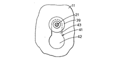
第2シート11は、図14に示されるように、フランジ39とシート37の間に挿入される。これは図17および図18に示されるように行われる。シート11に設けられたキーホール形スロット41は、フランジ39によって捕らえられるのに充分な狭さであるスロット部43と、それに連続するリベットの頭部のフランジ39を通すのに充分な大きさの拡大孔部42とを有している。拡大孔部42は突出するリベットの幹部21をそのフランジ39を越して通し、シート11は、図14および図18に示されるように、スロット部43がフランジ39の下側に係合するように、側方へスライドされる。
【0024】
打込用工具は、次いで突出するリベットの幹部に対して提供され、締着は径方向外側のアンビルを使用して、既述の第2操作を行うように工具を作動して完成される。この結果、フランジ39は第2シート11を第1シート37に締着するために第1シートの持ち上げられた表面34によって提供された凸型の変形用ダイ表面の方へ変形される。そして、リベットの幹部の引張部分は切断され、2枚のシート部材は、図15に示されるように、相互に締着される。
【0025】
図16,図17および図18はこの例の方法の特殊な適用を示し、ここでは3個のリベットが組立体の一方のシートに三角形の関係で提供され、対応する3個のキーホール形スロットが、組立体に締着される他方のシートに形成されている。
【0026】
この発明は上述の実施例の細部によって限定されるものでない。例えば、リベットの軸部に形成されるブラインドヘッドは別の形状とすることができる。その直径を徐々に増大したものに代えて、異なった直径の2個の球体から形成することができ、小直径のものは予め形成された頭部に近く、大直径のものは予め形成された頭部から離れている。このように級別の直径の球体を2個以上としてものも使用される。
【0027】
図4,図5および図6に示されるような同心の別々の内側および外側アンビルを有する、打込用工具を使用する代わりに、凹面をした単一のアンビルを有する打込工具を使用することもできる。なお、このような型の工具は、皿穴形状の予め形成された頭部を有し、その頭部をドーム状の形状に変形するブラインドリベットを設置するために、ブラインドリベットの打込の技術分野において既に知られている。この変形例が適用される場合には、図4,図5および図6に示される型の工具を必要とするよりも、恐らくは、より強く予め形成された頭部とより強い幹部とを有するリベットを必要とするだろう。
【図面の簡単な説明】
【図1】ブラインドリベットによって比較的薄い、変形可能な2枚のシートを相互に固着する方法を順次工程毎に説明するための要部断面図である。
【図2】ブラインドリベットによって比較的薄い、変形可能な2枚のシートを相互に固着する方法を順次工程毎に説明するための要部断面図である。
【図3】ブラインドリベットによって比較的薄い、変形可能な2枚のシートを相互に固着する方法を順次工程毎に説明するための要部断面図である。
【図4】リベット打込用工具の一部とともに示される図1Aに対応する断面図である。
【図5】リベット打込用工具の一部とともに示される図1Bに対応する断面図である。
【図6】リベット打込用工具の一部とともに示される図1Cに対応する断面図である。
【図7】比較的薄くて変形可能なシートと比較的厚くて強いシートとを相互に固着する方法を順次工程毎に説明するための要部断面図である。
【図8】比較的薄くて変形可能なシートと比較的厚くて強いシートとを相互に固着する方法を順次工程毎に説明するための要部断面図である。
【図9】比較的薄くて変形可能なシートと比較的厚くて強いシートとを相互に固着する方法を順次工程毎に説明するための要部断面図である。
【図10】比較的厚くて強いシートと比較的薄くて変形可能なシートとを相互に固着する方法を順次工程毎に説明するための要部断面図である。
【図11】比較的厚くて強いシートと比較的薄くて変形可能なシートとを相互に固着する方法を順次工程毎に説明するための要部断面図である。
【図12】比較的厚くて強いシートと比較的薄くて変形可能なシートとを相互に固着する方法を順次工程毎に説明するための要部断面図である。
【図13】比較的強いシートと比較的変形し易いシートとを相互に固着する他の方法を順次工程毎に示す要部断面図である。
【図14】比較的強いシートと比較的変形し易いシートとを相互に固着する他の方法を順次工程毎に示す要部断面図である。
【図15】比較的強いシートと比較的変形し易いシートとを相互に固着する他の方法を順次工程毎に示す要部断面図である。
【図16】図13,図14および図15に示される方法が適用される組立体の要部斜視図である。
【図17】組立体の平面図である。
【図18】図17の一部拡大図である。
【符号の説明】
11,12,31,33 部材
13,14 孔
15,35 ブラインドリベット
16 軸部
17 予め形成された頭部
19 ブレークネック
21 引張部分
22 拡大頭部
23,38 ブラインドヘッド
24 打込工具
25 外側アンビル
26 内側アンビル
27 コレット
28 顎
32 皿穴
34 傾斜表面
36 肩部
39 フランジ[0001]
BACKGROUND OF THE INVENTION
The present invention relates to a method for fastening a plurality of members to each other, and more particularly to a method for fastening a plurality of sheet-like members to each other so as to increase the resistance to relative slip.
[0002]
[Prior art]
For example, it is a common means to fasten sheet-like members such as metal panels to each other with fastening tools such as bolts, nuts, and rivets. Basically, the fastener is composed of a shaft portion through which a hole or hole in which each member is overlapped, and a pre-formed head at one end of the shaft portion. The pre-formed head is in contact with one surface of the member, and the second head is provided at the other end of the shaft portion. Since the second head is driven toward the pre-formed head (for example, by screwing a nut along the bolt and deforming the protruding portion of the shaft portion of the rivet), each member is driven by the head and the head. Are secured to each other. It is relatively easy to generate a tensile force on the shaft portion of the fastener so as to keep the members in contact with each other.
[0003]
[Problems to be solved by the invention]
However, it is also a general requirement to firmly suppress slippage between members in a direction parallel to the respective surfaces. In fact, achieving this is not that easy. This can be achieved by creating a hole in the member in which the shaft part of the fastener is tightly fitted, i.e. there is no gap between the shaft part of the fastener and the wall of each hole. Met. However, this is not easy to achieve, at least under the currently dominant manufacturing method.
[0004]
Each hole in a metal panel is usually made by punching each panel individually in a single process after assembling the panels in contact with each other, for example instead of drilling. The hole tolerance must be able to accommodate the maximum error in the diameter and position of the punched hole and the relative position of the panel during assembly. In addition, the holes on the front panel (the panel closer to the assembly worker) are moved away from the rear panel (farther from the assembly worker) to facilitate alignment of each hole and to help the assembly worker visually confirm the alignment of the holes. It is necessary to make it larger than the hole of the panel. Furthermore, it is usually sought to make the diameters of both holes somewhat larger than the diameter of the fastener shaft used to facilitate insertion of the fastener shaft into each hole. And preferred. That is, in practice, the holes of each member are made larger than the shaft portion of the fastener.
[0005]
Thus, as fastened to each other in this manner, when the members are pulled in opposite directions in a plane parallel to their contact surfaces, the forces that initially resist their relative movement are It is only the frictional force between the head and the head of the fastener that is maintained by the tensile force of the shaft and acts as a compressive force. In fact, this frictional force is limited in its strength and has a low resistance to initial relative slip between members. It is not a problem that the width of the first slip is small and the resistance to further slip is larger (when the hole wall of each member is in contact with the side surface of the shaft portion of the fastener). The first slip cannot be tolerated. The present invention eliminates such problems by increasing the resistance to such initial slip.
[0006]
[Means for Solving the Problems]
In order to solve the above problems, the present invention includes a step of inserting a shaft portion of a rivet through a hole of at least one member; a step of inserting a shaft portion of a rivet through a hole of at least the other member; Placing the second deforming die close to the periphery of the hole in one member; and moving the rivet head or head in the direction of each other; Then, each member is pressed between the two deformation dies so as to deform at least one member, and the periphery of the stacked holes is deformed in the lateral direction so that the sheet-like members are engaged with each other. And the rivet head and head maintain each member in its engaged relationship, thereby increasing the resistance of the member to relative slip, with each hole overlying and facing each other. A method of fastening a plurality of members of Jo, the rivet is a blind rivet, one of the deforming dies is characterized in that a head or heads of the rivet. Note that some embodiments of the present invention will be described by way of example with reference to the accompanying drawings.
[0007]
DETAILED DESCRIPTION OF THE INVENTION
Embodiments of the present invention will be described below. First, in the example shown in FIGS. 1, 2 and 3, the sheet-like member to be fastened is two relatively thin steel plates, and the
[0008]
Blind rivets with cutting trunks are generally known in the field of mechanical assembly and are generally similar to the well-known rivets and are marketed under the registered trademark “AVEX”. ing. Briefly, such a rivet comprises a steel shell including a
[0009]
The
[0010]
In this example, the end of the
[0011]
Normally, after assembling the shell on the trunk, for example, by applying compression (crimping) or rolling (rolling) to the shell shaft, or by changing the outer shape of the shaft by other means, blinds Adjusting the position and shape of the sphere of the head is well known in the field of designing and manufacturing blind rivets for cutting trunks. For example, wide compression to the shaft at its distal end (close to the head of the trunk) and narrow compression close to the
[0012]
Cutting trunk blind rivets are typically driven by pneumatically or hydraulically actuated tools, and such tools are well known in the art. 4, 5 and 6 show the relevant parts of the
[0013]
One suitable tool is an improvement under the name CHERRY, which is a registered trademark, G784 Hydroshift Riveter (HYDRO-SHIFT RIVETER). . The G784 tool has an anvil and jaw as described above, the initial contact of the rivet head against the
[0014]
The
[0015]
Subsequent operation of the tool advances the
[0016]
The underside of the shell head becomes increasingly concave as the rivet trunk is pulled into the shell and eventually reaches a position as shown in FIG. The subsequent increase in tensile force applied to the tension part of the trunk results in break neck breakage, the broken pieces of the tool and tension part are removed, the rivets are attached and the two sheets are clamped together. Worn.
[0017]
Thus, the two sheets are laterally deformed to engage each other, and this engagement is maintained by the compressive force generated by the pre-formed head and the rivet head and is maintained by the tensile force of the rivet shaft. The This lateral deformation of the sheet substantially increases the resistance of the sheet to relative slip as described above. Typically, the resistance of the sheet to the initial slip is about three times that provided by a cutting stem that does not deform the sheet in this way.
[0018]
An exemplary method of fastening the sheets shown in FIGS. 1, 2, 3 and 4, 4, 5 and 6 together is that the sheets are both relatively thin and pre-formed with a rivet blind head. This is suitable when sufficient deformation is possible by the force that can be applied to the head. However, if one or the other sheet is so strong that it cannot be deformed, the second embodiment will be used. This is a variation of the first embodiment, where a stronger sheet is used to provide one of the deforming dies instead of the rivet head.
[0019]
7, 8 and 9 (corresponding to FIG. 1, FIG. 2 and FIG. 3, respectively, equivalent parts are indicated by the same reference numerals) are used when the
[0020]
If the
[0021]
Still other examples are shown in FIGS. 13, 14, 15, 16, 17, and 18. FIG. In these examples, the rivet is initially mounted on one seat, leaving the trunk with the undeformed portion of the pre-formed head of the rivet, protruding from the front of the seat. A suitable part of the second sheet is then positioned between the head part and the first sheet. Then that part of the head is deformed to fasten the next sheet to the first sheet.
[0022]
Thus, the rivet 35 (FIG. 13) has been pre-deformed with a
[0023]
As shown in FIG. 14, the
[0024]
The driving tool is then provided to the protruding rivet trunk, and fastening is completed by operating the tool to perform the second operation described above using the radially outer anvil. As a result, the
[0025]
FIGS. 16, 17 and 18 show a special application of the method of this example, in which three rivets are provided in a triangular relationship on one sheet of the assembly and the corresponding three keyhole shaped slots. Is formed on the other sheet fastened to the assembly.
[0026]
The invention is not limited by the details of the embodiments described above. For example, the blind head formed on the shaft portion of the rivet can have another shape. Instead of gradually increasing its diameter, it can be formed from two spheres of different diameters, the small diameter being close to the pre-formed head and the large diameter being pre-formed It is away from the head. In this way, a sphere having a diameter of two or more grades is used.
[0027]
Instead of using a driving tool with concentric separate inner and outer anvils as shown in FIGS. 4, 5, and 6, use a driving tool with a single concave anvil You can also. This type of tool has a countersunk-shaped pre-formed head, and in order to install a blind rivet that transforms the head into a dome shape, a blind rivet driving technique is used. Already known in the field. When this variant is applied, it is likely that the rivet has a stronger pre-formed head and a stronger trunk than would require a tool of the type shown in FIGS. Would need.
[Brief description of the drawings]
BRIEF DESCRIPTION OF DRAWINGS FIG. 1 is a cross-sectional view of a main part for sequentially explaining, for each step, a method for fixing two relatively thin, deformable sheets to each other by blind rivets.
FIG. 2 is a cross-sectional view of an essential part for sequentially explaining a method of fixing two relatively thin and deformable sheets to each other by a blind rivet for each step.
FIG. 3 is a cross-sectional view of an essential part for sequentially explaining a method of fixing two relatively thin and deformable sheets to each other by a blind rivet for each step.
FIG. 4 is a cross-sectional view corresponding to FIG. 1A shown together with a part of the rivet driving tool.
FIG. 5 is a cross-sectional view corresponding to FIG. 1B shown together with a part of the rivet driving tool.
FIG. 6 is a cross-sectional view corresponding to FIG. 1C shown together with a part of the rivet driving tool.
FIG. 7 is a cross-sectional view of an essential part for sequentially explaining, for each step, a method for fixing a relatively thin and deformable sheet and a relatively thick and strong sheet to each other.
FIG. 8 is a cross-sectional view of an essential part for sequentially explaining, for each step, a method for fixing a relatively thin and deformable sheet and a relatively thick and strong sheet to each other.
FIG. 9 is a cross-sectional view of an essential part for sequentially explaining, for each process, a method for fixing a relatively thin and deformable sheet and a relatively thick and strong sheet to each other.
FIG. 10 is a cross-sectional view of an essential part for sequentially explaining, for each step, a method for fixing a relatively thick and strong sheet and a relatively thin and deformable sheet to each other.
FIG. 11 is a cross-sectional view of an essential part for sequentially explaining, for each step, a method for fixing a relatively thick and strong sheet and a relatively thin and deformable sheet to each other.
FIG. 12 is a cross-sectional view of an essential part for sequentially explaining, for each step, a method for fixing a relatively thick and strong sheet and a relatively thin and deformable sheet to each other.
FIG. 13 is a cross-sectional view of a main part illustrating another method for sequentially fixing a relatively strong sheet and a relatively easily deformable sheet to each other.
FIG. 14 is a cross-sectional view of a main part illustrating another method for sequentially fixing a relatively strong sheet and a relatively easily deformable sheet to each other.
FIG. 15 is a cross-sectional view of a main part showing another method for fixing a relatively strong sheet and a relatively easily deformable sheet to each other in sequence.
16 is a perspective view of an essential part of an assembly to which the method shown in FIGS. 13, 14 and 15 is applied. FIG.
FIG. 17 is a plan view of the assembly.
FIG. 18 is a partially enlarged view of FIG.
[Explanation of symbols]
11, 12, 31, 33
Claims (17)
Applications Claiming Priority (2)
| Application Number | Priority Date | Filing Date | Title |
|---|---|---|---|
| GB9501866.9 | 1995-01-31 | ||
| GB9501866A GB2297508A (en) | 1995-01-31 | 1995-01-31 | Method of riveting and blind rivet |
Publications (2)
| Publication Number | Publication Date |
|---|---|
| JPH08232928A JPH08232928A (en) | 1996-09-10 |
| JP3827169B2 true JP3827169B2 (en) | 2006-09-27 |
Family
ID=10768860
Family Applications (1)
| Application Number | Title | Priority Date | Filing Date |
|---|---|---|---|
| JP01447196A Expired - Fee Related JP3827169B2 (en) | 1995-01-31 | 1996-01-30 | Method for fastening a plurality of members |
Country Status (11)
| Country | Link |
|---|---|
| US (1) | US5697141A (en) |
| EP (1) | EP0725217B1 (en) |
| JP (1) | JP3827169B2 (en) |
| KR (1) | KR960029645A (en) |
| AT (1) | ATE192828T1 (en) |
| AU (1) | AU696017B2 (en) |
| BR (1) | BR9600272A (en) |
| CA (1) | CA2168198A1 (en) |
| DE (1) | DE69608146T2 (en) |
| ES (1) | ES2150070T3 (en) |
| GB (1) | GB2297508A (en) |
Families Citing this family (7)
| Publication number | Priority date | Publication date | Assignee | Title |
|---|---|---|---|---|
| GB2330390B (en) * | 1997-10-10 | 2001-10-17 | Avdel Textron Ltd | Blind riveting |
| US20040045147A1 (en) * | 2001-12-04 | 2004-03-11 | Swanstrom Kenneth A. | Resilient standoff fastener |
| US6751841B2 (en) * | 2002-06-10 | 2004-06-22 | Sun Microsystems, Inc. | Riveting method |
| WO2009094775A1 (en) * | 2008-01-29 | 2009-08-06 | Magna Seating Inc. | Conic flange pivot joint |
| DE102009003177B4 (en) * | 2009-05-18 | 2014-02-13 | Peter Lazic Gmbh | Implant for fixing adjacent bone plates |
| MX371271B (en) * | 2013-08-28 | 2020-01-22 | Pem Man Inc | Fastener with a belleville head. |
| RU2769143C1 (en) * | 2021-01-29 | 2022-03-28 | Владимир Александрович Грибановский | Rivet and method for obtaining a non-detachable rivet connection of parts without a two-way access to the rivet seam |
Family Cites Families (10)
| Publication number | Priority date | Publication date | Assignee | Title |
|---|---|---|---|---|
| NL57311C (en) * | ||||
| GB368712A (en) * | 1930-12-08 | 1932-03-08 | A E Jenks And Cattell Ltd | Improvements in conveyors used for conveying coal and for like purposes |
| GB427843A (en) * | 1934-03-20 | 1935-05-01 | George Geach Parnall | An improved method of making rivetted connections |
| US2047341A (en) * | 1934-07-19 | 1936-07-14 | Curtiss Aeroplane & Motor Co | Method of riveting |
| GB454733A (en) * | 1935-06-04 | 1936-10-07 | May Claude Hector | Improvements relating to rivetted joints |
| US2397111A (en) * | 1942-08-10 | 1946-03-26 | Huxon Holding Corp | Rivet |
| US4112811A (en) * | 1977-04-15 | 1978-09-12 | John Olmsted King | Self-dimpling fastener pin |
| GB2157788B (en) * | 1984-04-11 | 1988-02-10 | Anthony John Nield | Anchoring devices |
| US4639175A (en) * | 1984-05-15 | 1987-01-27 | Phillips Plastics Corp. | Self-sealing expansion rivet assembly |
| US4897004A (en) * | 1986-06-26 | 1990-01-30 | Textron, Inc. | Blind fastener with self-locking collar |
-
1995
- 1995-01-31 GB GB9501866A patent/GB2297508A/en not_active Withdrawn
-
1996
- 1996-01-26 ES ES96300584T patent/ES2150070T3/en not_active Expired - Lifetime
- 1996-01-26 AT AT96300584T patent/ATE192828T1/en not_active IP Right Cessation
- 1996-01-26 CA CA002168198A patent/CA2168198A1/en not_active Abandoned
- 1996-01-26 DE DE69608146T patent/DE69608146T2/en not_active Expired - Lifetime
- 1996-01-26 EP EP96300584A patent/EP0725217B1/en not_active Expired - Lifetime
- 1996-01-29 US US08/593,335 patent/US5697141A/en not_active Expired - Lifetime
- 1996-01-30 AU AU42270/96A patent/AU696017B2/en not_active Ceased
- 1996-01-30 BR BR9600272A patent/BR9600272A/en not_active Application Discontinuation
- 1996-01-30 JP JP01447196A patent/JP3827169B2/en not_active Expired - Fee Related
- 1996-01-31 KR KR19960002354A patent/KR960029645A/ko not_active Application Discontinuation
Also Published As
| Publication number | Publication date |
|---|---|
| GB2297508A (en) | 1996-08-07 |
| ATE192828T1 (en) | 2000-05-15 |
| DE69608146D1 (en) | 2000-06-15 |
| AU4227096A (en) | 1996-08-08 |
| CA2168198A1 (en) | 1996-08-01 |
| EP0725217A1 (en) | 1996-08-07 |
| US5697141A (en) | 1997-12-16 |
| ES2150070T3 (en) | 2000-11-16 |
| DE69608146T2 (en) | 2001-01-25 |
| AU696017B2 (en) | 1998-08-27 |
| JPH08232928A (en) | 1996-09-10 |
| BR9600272A (en) | 1997-12-23 |
| KR960029645A (en) | 1996-08-17 |
| EP0725217B1 (en) | 2000-05-10 |
| GB9501866D0 (en) | 1995-03-22 |
Similar Documents
| Publication | Publication Date | Title |
|---|---|---|
| EP1225990B1 (en) | Rivet and riveted joint structure | |
| JP4727913B2 (en) | Automatic perforated blind fastener | |
| EP1141560B1 (en) | Blind fastener | |
| EP0614405B1 (en) | Improved panel clinching methods | |
| AU731595B2 (en) | Self-coining fastener | |
| US20130243542A1 (en) | Blind rivet with a plastic rivet body | |
| EP1614486A1 (en) | Self-piercing rivet fastening device with improved die | |
| KR101022132B1 (en) | Blind fastener and method of removing it from a workpiece | |
| EP0725221B1 (en) | Method of fastening members of an assembly | |
| EP1021260B1 (en) | Blind riveting | |
| JP3827169B2 (en) | Method for fastening a plurality of members | |
| EP1327082B1 (en) | Blind fastener | |
| EP0728950A1 (en) | Method of securing members together and fastener therefor | |
| US6842962B1 (en) | Sheet joining method and apparatus and a rivet for use in the method | |
| JPS62148035A (en) | Joining device for metallic thin sheet | |
| EP0791757A1 (en) | Blind rivet | |
| JP2003220440A (en) | Device for fastening automatic drilling rivet |
Legal Events
| Date | Code | Title | Description |
|---|---|---|---|
| A131 | Notification of reasons for refusal |
Free format text: JAPANESE INTERMEDIATE CODE: A131 Effective date: 20050726 |
|
| A601 | Written request for extension of time |
Free format text: JAPANESE INTERMEDIATE CODE: A601 Effective date: 20051026 |
|
| A602 | Written permission of extension of time |
Free format text: JAPANESE INTERMEDIATE CODE: A602 Effective date: 20051114 |
|
| A521 | Request for written amendment filed |
Free format text: JAPANESE INTERMEDIATE CODE: A523 Effective date: 20060126 |
|
| TRDD | Decision of grant or rejection written | ||
| A01 | Written decision to grant a patent or to grant a registration (utility model) |
Free format text: JAPANESE INTERMEDIATE CODE: A01 Effective date: 20060606 |
|
| A61 | First payment of annual fees (during grant procedure) |
Free format text: JAPANESE INTERMEDIATE CODE: A61 Effective date: 20060630 |
|
| R150 | Certificate of patent or registration of utility model |
Free format text: JAPANESE INTERMEDIATE CODE: R150 |
|
| S531 | Written request for registration of change of domicile |
Free format text: JAPANESE INTERMEDIATE CODE: R313531 |
|
| S533 | Written request for registration of change of name |
Free format text: JAPANESE INTERMEDIATE CODE: R313533 |
|
| R350 | Written notification of registration of transfer |
Free format text: JAPANESE INTERMEDIATE CODE: R350 |
|
| FPAY | Renewal fee payment (event date is renewal date of database) |
Free format text: PAYMENT UNTIL: 20090714 Year of fee payment: 3 |
|
| FPAY | Renewal fee payment (event date is renewal date of database) |
Free format text: PAYMENT UNTIL: 20100714 Year of fee payment: 4 |
|
| FPAY | Renewal fee payment (event date is renewal date of database) |
Free format text: PAYMENT UNTIL: 20110714 Year of fee payment: 5 |
|
| FPAY | Renewal fee payment (event date is renewal date of database) |
Free format text: PAYMENT UNTIL: 20110714 Year of fee payment: 5 |
|
| FPAY | Renewal fee payment (event date is renewal date of database) |
Free format text: PAYMENT UNTIL: 20120714 Year of fee payment: 6 |
|
| FPAY | Renewal fee payment (event date is renewal date of database) |
Free format text: PAYMENT UNTIL: 20130714 Year of fee payment: 7 |
|
| R250 | Receipt of annual fees |
Free format text: JAPANESE INTERMEDIATE CODE: R250 |
|
| R250 | Receipt of annual fees |
Free format text: JAPANESE INTERMEDIATE CODE: R250 |
|
| LAPS | Cancellation because of no payment of annual fees |