JP3825052B2 - Optical oximeter probe adapter - Google Patents
Optical oximeter probe adapter Download PDFInfo
- Publication number
- JP3825052B2 JP3825052B2 JP52304397A JP52304397A JP3825052B2 JP 3825052 B2 JP3825052 B2 JP 3825052B2 JP 52304397 A JP52304397 A JP 52304397A JP 52304397 A JP52304397 A JP 52304397A JP 3825052 B2 JP3825052 B2 JP 3825052B2
- Authority
- JP
- Japan
- Prior art keywords
- probe
- adapter
- wire
- terminal
- emitter
- Prior art date
- Legal status (The legal status is an assumption and is not a legal conclusion. Google has not performed a legal analysis and makes no representation as to the accuracy of the status listed.)
- Expired - Fee Related
Links
Images


Classifications
-
- A—HUMAN NECESSITIES
- A61—MEDICAL OR VETERINARY SCIENCE; HYGIENE
- A61B—DIAGNOSIS; SURGERY; IDENTIFICATION
- A61B5/00—Measuring for diagnostic purposes; Identification of persons
- A61B5/145—Measuring characteristics of blood in vivo, e.g. gas concentration, pH value; Measuring characteristics of body fluids or tissues, e.g. interstitial fluid, cerebral tissue
- A61B5/1455—Measuring characteristics of blood in vivo, e.g. gas concentration, pH value; Measuring characteristics of body fluids or tissues, e.g. interstitial fluid, cerebral tissue using optical sensors, e.g. spectral photometrical oximeters
- A61B5/14551—Measuring characteristics of blood in vivo, e.g. gas concentration, pH value; Measuring characteristics of body fluids or tissues, e.g. interstitial fluid, cerebral tissue using optical sensors, e.g. spectral photometrical oximeters for measuring blood gases
-
- A—HUMAN NECESSITIES
- A61—MEDICAL OR VETERINARY SCIENCE; HYGIENE
- A61B—DIAGNOSIS; SURGERY; IDENTIFICATION
- A61B2560/00—Constructional details of operational features of apparatus; Accessories for medical measuring apparatus
- A61B2560/04—Constructional details of apparatus
- A61B2560/0443—Modular apparatus
- A61B2560/045—Modular apparatus with a separable interface unit, e.g. for communication
-
- A—HUMAN NECESSITIES
- A61—MEDICAL OR VETERINARY SCIENCE; HYGIENE
- A61B—DIAGNOSIS; SURGERY; IDENTIFICATION
- A61B2562/00—Details of sensors; Constructional details of sensor housings or probes; Accessories for sensors
- A61B2562/08—Sensors provided with means for identification, e.g. barcodes or memory chips
-
- G—PHYSICS
- G01—MEASURING; TESTING
- G01N—INVESTIGATING OR ANALYSING MATERIALS BY DETERMINING THEIR CHEMICAL OR PHYSICAL PROPERTIES
- G01N35/00—Automatic analysis not limited to methods or materials provided for in any single one of groups G01N1/00 - G01N33/00; Handling materials therefor
- G01N35/00584—Control arrangements for automatic analysers
- G01N35/00722—Communications; Identification
- G01N35/00732—Identification of carriers, materials or components in automatic analysers
Description
技術分野
本発明は、一般に、光学酸素計に関し、特に、関連した酸素計モニターで使用できるように設計/配列された光学酸素計プローブを異なった酸素計モニターで使用可能にするアダプタに関する。
図面中の符号について
図面中、同一の構成要素は、各図、同一の符号にて示す。
発明の背景
健康な人体の新陳代謝において酸素が重要であることから、患者の血中酸素含有量を計測できるということが重要である。手術中や手術後の患者の動脈血のヘモグロビン酸素飽和度をモニターすることは、特に重要である。
指等の患者の皮膚を通じて動脈血を含んでいる領域に光を直射する非侵襲式の酸素計が開発されてきた。この光は、典型的に、二つ又はそれ以上の光の一次波長を含んでいる。このような酸素計の例は、米国特許第5209230号("Adhesive Pulse Oximeter Sensor With Reusable Portion"、Swedlowら)、及び米国特許第4700708号("Calibrated Optical Oximeter Probe"、New,Jrら)に開示されており、これらは本発明の参照文献であり、なお、これらは両方とも本発明の特許出願人に譲渡されているものである。New,Jrらの特許の酸酸素計は、モニターに取り付けられるプローブを含み、このプローブは、モニターにより計測できる抵抗を有する抵抗器を収容する。この抵抗の計測値は、患者の表皮を通じ発光ダイオード(LED)から直射した光の波長を示す。モニターは、この情報と、これら波長で検出された光の計測強度とを使用して、患者の動脈血酸素含有量を計算する。これら二つの波長の各々における光吸収量を別々に計測するために、LEDは、重複しない時間間隔で作動される。
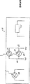
光学プローブは、複数の形態で電気的に配列される。米国特許第5249576号("Universal Pulse Oximeter Probe"、Goldbergerら)は、患者の指に光を放射する赤色(又はRED)発光ダイオード(LED)と赤外線(又はIR)発光ダイオード(LED)の二つの配列形態を説明する。これら二つの従来技術の配列形態を図1及び2に示す。図1は、一対のLED11、12を"三線配列"13で連結したプローブ10の構成を示し、二つのLEDアノードが端子14に連結され、二つのLEDカソードが、それぞれ、個別のリード線15、16に連結されている。このプローブは、また、LED11、12から放射した光を検出する光電検出器17と、LED11及び12のうちの少なくとも一つにより発生される光の波長を示す抵抗を有する抵抗器18とを含む(ここで、変形的に、抵抗は、その他の、又は付加的なパラメータを示すことができる)。以下、LEDの三線配列を有するプローブを"三線式プローブ"10という。LEDのリード線14、15及び16は、それぞれ、接地、VO1及びVO2で示す。VO1及びVO2といった表示は、これらが本願の出願人であるネルコー社以外により製造された酸素計用の第一及び第二のLED駆動電圧リード線を示す。ここで、表示VO1及びVO2にある"O"は"other"、すなわち"以外又は他の"を表す。このことから、このプローブを"以外又は他のプローブ"という。
図2に示す第二の例では、二つのLED21、22が"二線配列"23で連結され、第一のLED21のアノード及び第二のLED22のカソードが第一のリード線24に連結され、第一のLED21のカソード及び第二のLED22のアノードが第二のリード線25に連結される。このプローブは、また、光電検出器26及び抵抗器27(又は、これらLEDの一つ又は両方により発生される波長、及び/又は他のパラメータを示す他のタイプの機構)を含む。以下、LEDの二線配列を有するプローブを"二線式プローブ"20という。LEDへのリード線をネルコープローブの第一及び第二の電圧信号に対応するVN1及びVN2で示す。このタイプのプローブを"ネルコープローブ"という。
以下、LEDの二線配列を有するプローブを使用するために設計した酸素計モニターを"二線式モニター"又は"ネルコー酸素計モニター"という。同様に、LEDの三線配列を有するプローブを使用するために設計した酸素計モニターを"三線式モニター"又は"他の酸酸素計モニター"という。
幾つかの酸素計プローブは、一つ又はそれ以上のLEDを付加し得る。例えば、第2の赤色LEDを第1の赤色LEDと組み合わせて使用した、より平衡した光のレベルを達成することができる。
上記した図1及び2の二つの配列形態のいずれにおいても、二つのLEDのうちの一つだけがいずれの与えられた時間においても作動されるように電力が二つのLEDに印加されて、いずれの与えられた時間においても、検出器からの出力信号が、二つのLEDのうちの多くても一つからの光に応答して発生される。これは、検出した光の強度を患者の血中酸素濃度の表示へ変換するために必要な計算を簡素化する。
異なったタイプのプローブと、異なったタイプの酸素計との間の不一致が、両方のタイプの酸素計にプローブを供給するコストを著しく増大させる。特に、このようなプローブの製造においては、多くの異なったタイプのプローブの設計にコストがかかるだけでなく、多くの異なった生産ラインの組立て、多くの異なった生産ライン用機械の購入、多くの異なった生産ライン用機械の修繕、及び多くの異なったタイプのプローブの販売にコストがかかる。また、異なったタイプのプローブの各々の製造及び配給にかかるコストは、ただ一つのタイプのプローブの場合に増大する製品生産量に関連した経済性からみると有益でない。これらプローブの全コストは、また、両方のタイプのプローブを使用する病院でかかる間接的なコストをも含み、このような病院では、各々のタイプのプローブの少量の注文に関連したコストが増大し、多くの異なったタイプのプローブの保管にコストがかかり、多くの売り主との折衝にコストがかかる。これら全ての要因は、患者の酸素飽和度を監視することにかかるコストを著しく増大させる。
上記のGoldbergerの特許は、いずれの酸素計とも使用できるように配列できるプローブを提供することによって、この問題を処理する。このプローブ内の光電検出器及び光源は、いかなる相互連結もせずに取り付けられており、ケーブルが、適当に挿入したジャンパリード線の手段による多様な配列形態でこれら構成要素を相互に連結している。しかし、この構造が、このプローブを多種の酸素計に適合させることができるのであるが、相互に連結した電気的な構成要素を有するプローブを任意に選択したいずれの酸素計とも使用することができない。
本発明の目的は、第一の配列形態で相互に連結した電気的な構成要素を有するプローブと、電気的に相互連結した第二の配列形態を有するプローブを使用するために設計したモニターとの間を、両者が相互に有効に機能するように、連結できるアダプタを提供することである。
発明の概要
本発明は、二線式酸素計プローブ又はモニターを三線式モニター又はプローブに能動的に連結するアダプタを提供する。これは、アダプタの連結を切り換えるための制御信号を与える酸素計モニターからの駆動信号を交互して能動的に行われる。アダプタの連結は、好適に、ダイオード、トランジスタ、又は他の能動素子でなされる。
このことから、本発明のアダプタは、まず、三線式デバイスの第一及び第二の端子の間に二線式デバイスの二つのリード線を連結し、第一の光エミッタを作動し、次に、三線式デバイスの第二及び第三の端子の間に上記の二つのリード線を連結する。三線式デバイスは、酸素計モニター又は酸素計プローブのいずれかであり得る。
一つのタイプの三端子モニターでは、二つの駆動端子(VO1、VO2)のうちの一つだけが、ある時間に作動し、このとき、他の駆動端子は高インピーダンス状態にあり、第三の駆動端子は接地されている。このような配列形態では、アダプタは、他の駆動端子と切断する必要がない。他のタイプの三端子モニターでは、第二の駆動端子が高インピーダンス状態にない。このことから、本発明に従った一つのアダプタは、付加的なスイッチにより、使用しない第二の駆動端子を絶縁する。一つの実施例は、二つのトランジスタをもつスイッチの実施例でも、二つのダイオードの実施例でもない、四つのトランジスタをもつスイッチの実施例である。
図示の好適実施例の二つのタイプのアダプタは、酸素計プローブを別のやり方では使用不可能の酸素計モニターと使用できるように適合する。これら二つのタイプのアダプタは、酸素計プローブの広く使用されている二つのタイプの両方に関連したタイプの酸素濃度モニターで使用できる点で特に有用である。
本発明のアダプタは、好適に、モニターや、モニターにプローブを連結するために使用するケーブルに取り付けられて、各アダプタは、モニター自身の延長部となり、多くの異なった患者が使用でき、各患者が何回も使用することができる。
後述する特定の二つのタイプのモニター及びプローブとの使用のための多様な好適なアダプタの実施例を特定的に説明する。しかし、本発明は、異なった数や配列形態の光源信号接続を有するプローブ及びモニターを相互連結するいずれのアダプタにも適用可能である。
本発明は、また、三線式及び二線式の両方のモニターのためのLEDを含む二重使用のプローブを提供する。LEDは、使用するモニターに要求される特定の配列を与えるために相互連結を外部で行うことで、プローブの二重使用を可能にしたので、プローブ自身の内部で相互連結されない。しかし、全てのLEDが対をなすようにするのではなく、IR LEDだけが再生され、全てのLEDのための共通のコネクタにより赤色LEDが両方のタイプのモニターのために使用でき、一つ又はその他のIR LEDだけが連結又は使用される。これに対し、Goldbergerの特許では、三つのLEDのリード線が、二線式又は三線式の酸素計にプローブを連結するために要求されるだけである。
【図面の簡単な説明】
図1は、一対のLEDの三線配列を有するプローブを示す。
図2は、一対のLEDの二線配列を有するプローブを示す。
図3は、二線式モニターを三線式プローブに連結するための二対三型アダプタとしての二極双投スイッチを示す。
図4は、三線式モニターを二線式プローブに連結するための三対二型アダプタとしての二極双投スイッチを示す。
図5は、二対三型アダプタの第一の好適実施例を示す。
図6は、三対二型アダプタの第一の好適実施例を示す。
図7は、二対三型アダプタの第二の好適実施例を示す。
図8は、高インピーダンス出力酸素計モニターとの使用のための三対二型アダプタの第二の好適実施例を示す。
図9は、組合せアダプタケーブルを示す。
図10は、組合せアダプタ用の図9のケーブルの多くのアダプタ連結を示す。
図11は、二重使用のプローブ及び対応するアダプタの好適実施例を示す。
好適実施例の説明
モニターのタイプ
他の三線式モニター:このモニターは、三線配列で連結した一対のLEDを駆動するように設計され、上設したように、二つのLEDアノードが、共通のリード線に連結され、二つのLEDカソードが、それぞれ、個別のリード線に連結されている。
したがって、このタイプのモニターは、このタイプのプローブに連結するための以下の三つの端子を有する。すなわち、これら二つのLEDのうちの第一のLEDのカソードに連結するための第一の端子、これら二つのLEDのうちの第二のLEDのカソードに連結するための第二の端子、及び両方のアノードに連結するための第三の端子である。以下でわかるように、アダプタを使用してこのタイプのモニターに二線式プローブを相互に連結するとき、これら三つの端子のうちの二つだけが常にプローブへ電気を伝える。
ネルコーの二線式モニター:これら二つのタイプの酸素計モニターの第二のモニターが、二線配列で連結した一対のLEDを駆動するように設計され適合され、第一のLEDのアノードと第二のLEDのカソードとが第一のリード線に連結され、第一のLEDのカソードと第二のLEDのアノードとが第二のリード線に連結されている。
したがって、このタイプのモニターは、このタイプのプローブに連結するための以下の二つの端子を有する。すなわち、第一のリード線に連結するための第一の端子、及び第二のリード線に連結するための第二の端子である。
変形的に、他のタイプの端子を使用してもよい。三線式プローブの変形物では、その一方のLEDのアノードが、共通の端子(接地)のための他方のLEDのカソードに連結されている二つのLEDを有し得る。また、他の変形物では、二つのアノードではなく、二つのカソードが、共通の端子に連結され得る。
アダプタのタイプ
第一のタイプのアダプタは、三線式酸素計モニターと、二つのLEDの二線配列を有する酸素計プローブとを駆動可能にする。以下、このタイプのアダプタを"三対二型アダプタ"という。
また、第二のタイプのアダプタは、二線式酸素計モニターと、二つのLEDの三線配列を有する酸素計プローブとを駆動可能にする。以下、このタイプのアダプタを"二対三型アダプタ"という。このことから、これら二つのタイプのアダプタは、これら二つのタイプの酸素計モニターの各々と、これら二つのタイプの酸素計プローブの両方との使用を可能にする。
これら二つのタイプのアダプタの各々のために、アダプタは、モニターからプローブへの電気的経路の多数の異なった地点に取り付けられる。特に、モニター内部、モニターのフロントパネルの外部、モニターにプローブを連結するケーブル内部、ケーブルのモニター端部のコネクタ、又は、プローブへのコネクタに取り付けられる。
これら二つのタイプのアダプタは、各々、(1)LED駆動信号を、一つのタイプのモニターから、他のタイプのモニターと作動するように設計されたプローブにより見込まれるそのタイプのLED駆動信号へ変換し、(2)このプローブからのデータを、モニターにより見込まれるフォーマットでモニターに転送するように機能しなければならない。
これらのタイプのうちの一つのタイプのモニターによって発生される形状のLED駆動信号をこれらのタイプのうちの他のタイプのモニターによって発生される形状のLED駆動信号へ変換するために、モニターから受信した入力信号の部分を選択的に再び書き換えることが必要である。これは、プローブのLEDに電力を与え、且つ所望の出力信号を発生させるためにアダプタを制御するためのタイミングデータを与える、という二つの役割で、モニターによって発生されるLED駆動信号を使用することによって達成される。ここに与えられたアダプタの好適実施例は、能動スイッチを使用して、LED駆動信号をLEDに印加される信号に適合する。
好適実施例では、アダプタは、二極双投(DPDT)スイッチの形状を有し、これは、モニターからの少なくとも一つのLED駆動信号に応答して能動的に切り替えられる。しかし、三対二型アダプタが、一対のLED駆動信号VO1、VO2を一対のLED駆動信号VN1、VN2へ変換させるいずれの構造によっても与えられ得る。同様に、二対三型アダプタが、一対のLED駆動信号VN1、VN2を一対のLED駆動信号VO1、VO2へ変換させるいずれの構造によっても与えられ得る。
三対二型アダプタは、三線式モニターからのLED駆動信号を二線式プローブに要求されるLED駆動信号へ変換しなければならず、また、二対三型アダプタは、二線式モニターからのLED駆動信号を三線式プローブに要求されるLED駆動信号へ変換しなければならない。
以下の二項目では、これら二組のプローブ、モニター及び信号の特定的な例について説明する。
三線式モニターと三線式プローブの作動
三線式モニター51では、第一の端子が開状態(つまり、高インピーダンス状態)に切り換えられて無信号であるか又は負の電圧に駆動される信号VO1(図1及び4に示す)を第一の端子に与える。第二の端子が開状態(つまり、高インピーダンス状態)に切り換えられて無信号であるか又は負の電圧に駆動される信号VO2(図1及び4に示す)を第二の端子が与える。また、第三の端子の共通の接地帰線GNDが設けられる。このモニターは、三線式プローブとの使用のため、共通の接地帰線が、図1に示すLED11、12のアノードに連結される。変形的に、共通の端子は正の電圧に接続され、他の端子は交互に接地される。
VO1が負のときLED12は光を放射し、VO2が負のときLED11は光を放射する。VO1及びVO2を同時に負にすることはなく、与えられた時間に、LED11及び12のうちの一つだけが作動されるか、又は両方とも作動されない。これは、患者が一度に一つの波長だけを受けて、光電検出器が、与えられた時間に多くても一つの光の波長のための光学信号を受信することを確実にしている。これは、光電検出器17で受信した光に含まれるスペクトルデータの分析を簡素化する。選択的に、両方のLEDを外すと暗信号も計測される。
二線式モニターと二線式プローブの作動
二線式モニター41では、第一の端子が信号VN1(図2及び3に示す)を与え、第二の端子が信号VN2(図2及び3に示す)を与える。このモニターは、二線式プローブと使用するためのものである。
VN1が高く、VN2が低いとき、LED21が光を放射する。VN2が高く、VN1が低いとき、LED22が光を放射する。これら二つの信号のためのラインのいずれかが開状態(つまり、高インピーダンス状態)である場合、いずれのLEDもオン状態ではない。VN1及びVN2が両方のLEDの逆の端部に印加されるので、VN1及びVN2が、同時に、両方とも等しく高いか又は両方とも等しく低い場合、正味電圧降下が両方のLEDにわたってゼロとなり、したがって、両方のLEDは、この時間の間、オフ状態である。LEDを通過する電流は、典型的に、モニターのLEDドライバーにある回路を制限することによって制限される。
アダプタの一般的な構造
三対二型アダプタは、入力信号VO1、VO2(図1に示す)に応答して信号VN1、VN2(図2に示す)を生成できるいずれの構造形態をとってもよい。
好適実施例に従って、アダプタは、各々、二極双投スイッチ(以下、"DPDTスイッチ"という)の形態で与えられ、モニターにより与えられた信号のうちの一つ又は両方に応答して切り換えられる。このことから、酸素計モニターからのこのような信号は、関連したLEDに電力を与えるためと、アダプタの切り換えを制御するためとの二つの役割に使用される。LED駆動電流は、所望の光レベルを検出器で達成するために、酸素計によって変化される。これらスイッチは、可能な電流レベルの全範囲にわたって作動されるように、選択されなければならない。
二対三型アダプタ
図3は、二線式モニター41を三線式プローブ10へ連結するための二対三型アダプタとしての二極双投(DPDT)スイッチ90の使用を示す。入力信号VN1が、DPDTスイッチ90の第一の入力リード線42に印加され、入力信号VN2が、DPDTスイッチ90の第二の入力リード線43に印加される。このDPDTスイッチの作動は、入力リード線42、43及び出力リード線46-49を有する一対の一極双投(SPDT)スイッチ44、45のようにこのスイッチをみれば、容易に理解できる。出力リード線46、49の両方は、短絡され、ダイオード11、12の共通のアノード端子410に連結される。出力リード線47は、LED12のカソード411に連結され、出力リード線48は、LED11のカソード412に連結される。
SPDTスイッチが、LED11だけを作動させる第一の状態、又はLED12だけを作動させる第二の状態のいずれかの状態にあるように、制御信号Cが、これらSPDTスイッチの状態を制御する。第一の状態は、SPDTスイッチ44、45の実線部分で示し、第二の状態は、SPDTスイッチ44、45の破線部分で示す。変形例では、制御信号Cは、リード線43からのものであり得る。
この第一の状態では、正の入力リード線42が、出力リード線46を通じて共通のアノード410に連結され、負の入力リード線43が出力リード線48を通じてLED11のカソード412に連結されて、LED11だけがオン状態にされる。第二の状態では、負の入力リード線42が、出力リード線47を通じてLED12のカソード411に連結され、正の入力リード線43が、出力リード線49を通じて共通のアノード410に連結されて、LED12だけがオン状態にされる。このことから、LED11を横切って発生する信号パターンは、VO1と実質的に同一であり、LED12を横切って発生する信号パターンは、VO2と実質的に同一となる。
三対二型アダプタ
図4は、入力信号VO1、VO2で二線式プローブ20を駆動できる二極双投(DPDT)スイッチを使用する、三対二型アダプタの実施例を示す。
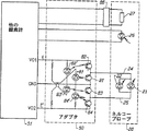
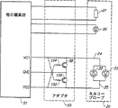
図4では、二極双投スイッチ92が、三対二型アダプタのように機能し、三線式モニター51を二線式プローブ20へ連結する。入力信号VO1がDPDTスイッチ92の第一の入力リード線52に印加され、入力信号VO2がDPDTスイッチ92の第二の入力リード線53に印加され、モニターの接地GNDがDPDTスイッチ92の第三の(共通の)入力リード線54に連結される。
制御信号D(この実施例では、VO1から得られる)は、DPDTスイッチの状態を制御する。このDPDTスイッチの作動は、一対の一極双投スイッチ55、56と同じものとして理解することができる。第一の状態(SPDTスイッチ55、56の実線で示す)は、VO1が負であり且つVO2がオフ状態にあり、プローブ20の第一の入力リード線58に連結した第一の出力リード線57にVO1が印加され、プローブ20の第二のリード線510に連結した第二の出力リード線59に接地GNDが連結されたときの状態であり、LED22だけがオン状態にある。
第二の状態(SPDTスイッチ55、56の破線部分で示す)は、VO1がオフ状態にあり且つVO2が負であり、VO2が出力リード線59に印加され、接地GNDが出力リード線57に連結されたときの状態であり、LED21だけがオン状態にある。このことから、LED21を横切って発生する信号パターンは、VN1と実質的に同一であり、LED22を横切って発生する信号パターンは、VN2と実質的に同一である。
装着
アダプタ40、50は、様々な異なったやり方で酸素計システム内に装着される。これらアダプタは、モニターの内部に含まれ、又はモニターからの適当なリード線に連結されるようにモニターのフロントパネル上に取り付けられ、又はプローブをモニターへ連結するケーブル(ケーブルの長さに組み継いだハウジング)に含まれ、又はプローブからの適当なリード線に連結されるようにプローブの入力端部に取り付けられ、又はプローブの内部に含まれ得る。ケーブル及び/又はモニターに着脱可能に連結されるアダプタを有することが好適であり、ユーザーが、上述のタイプのプローブの各々と他のタイプのモニターとを使用するために、このようなアダプタを使用できる。
好適実施例
図5は、図3に示すアダプタに一致する二対三型アダプタ40の一つの好適実施例を示す。このアダプタで、二線式モニター41と三線式プローブ10を駆動できる。このアダプタは、LED60-63と、これに対応する光トランジスタ60'-63'とを含むDPDTスイッチ90を含む。光学的な連結は、作動させるためにこのDPDTスイッチのLEDのモニターによって与えられる電流とは別の外部電力を必要としない。抵抗器Rを使用することによって光学スイッチへの電流を低く維持することが重要であり、これは、アダプタが、入力信号VN1、VN2により与えられる電流の幾らかを消耗し、プローブのLED11、12に印加される電流の量を低下させてしまうからである。
VN1が高く、VN2が低い(DPDTスイッチ90の第一の状態)とき、LED62、63は、それぞれ、光トランジスタ62′、63′へ光を放射し、これにより、信号VN2が、光トランジスタ63′、LED12、及び光トランジスタ62′を通じてVN1に接続される。これは、LED12をオン状態にする。しかし、LED60、61が逆にバイアスされているので、関連した光トランジスタ60′、61′がオフ状態にあり、LED11はオフ状態にある。
VN1が低く、VN2が高い(DPDTスイッチ40の第二の状態)とき、LED60、61は、それぞれ、光トランジスタ60′、61′へ光を放射し、これにより、信号VN1が、光トランジスタ61′、LED11、及び光トランジスタ60′を通じてVN2に接続される。これは、LED11をオン状態にする。しかし、LED62、63が逆にバイアスされているので、関連した光トランジスタ62′、63′はオフの状態にあり、LED12はオフの状態にある。
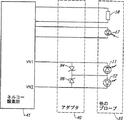
図6は、切換トランジスタ81-84と制御LED81'-84'とを有する四つ一組の光学的に絶縁したスイッチを使用する三対二型アダプタの第一の好適実施例を示す。スイッチ入力(LED81'-84')を制限する抵抗電流は、能動的な切り換えのための電力消費を最少にする。これら光学的に接続した実施例は、典型的に、入力信号の80-90%の電力をアダプタからの出力信号へ通過させる。VO1は、プローブへ選択的にゲート制御される入力信号として機能し、また、第一の制御信号Eとしても機能する。同様に、VO2は、プローブへ選択的にゲート制御される入力信号として機能し、また、第二の制御信号E'としても機能する。スイッチ81、84は、VO2が負であるときにのみ伝導性であり、スイッチ82、83は、VO1が負であるときにのみ伝導性である。VO1及びVO2が両方ともゼロボルトであるとき、全てのスイッチ81-84は非伝導性であり、LED21、22のいずれもオン状態にない。VO1が負であり、VO2がゼロボルトであるとき、スイッチ82、83のみがオン状態にある。これは、スイッチ82を通じてリード線24(それを負にする)にVO1を印加し、これにより、LED22が、接地GNDへ符号83を通じてオン状態にされ、LED21がオフ状態にされる。VO1がゼロボルトでVO2が負であるとき、スイッチ81、84のみがオン状態にある。これは、スイッチ84を通じてリード線25(それを負にする)にVO2を印加し、これにより、LED21が接地GNDへ符号81を通じてオン状態にされ、LED22がオフ状態にされる。VO1及びVO2は両方とも同時に低くなることはなく、それで、LED21のみオン状態、LED22のみオン状態、又はLED21及びLED22の両方がオフ状態、といった三つの別々の状態だけがある。
図6の実施例は、直接連結して、トランジスタ82、84(対応するLED81'-84')を除くように変更できる。トランジスタ82、84は、未使用時に、VO1及びVO2を絶縁する働きをし、これは、未作動時に、VO1及びVO2のためのラインが高インピーダンス状態にある場合に必要でない。出力が高インピーダンスであるときに働き得る実施例が、以下で説明する図8に示される。
図6は、また、外部のコード化素子86も示し、これは、コード化抵抗器27と並列(又は、変形的に、直列)に加入され、その値を、異なったタイプのモニターにより見込まれる値へ変更する(素子86は、抵抗器、又は幾つかの他の能動又は受動素子であり得る)。これは、異なったモニターが、幾つかの波長のための異なった抵抗値を使用するので、有用である。これは、図6の実施例だけでなく、図示のプローブ又はアダプタのいずれにも加入できる。
図7は、二対三型アダプタ40の第二の好適実施例を示す。このアダプタは、二つのショットキーダイオード94、96を使用する。VN1が高いとき、電流が、ショットキーダイオード94を通じて共通のノードへ流れ、LED12を通じて、このとき低いVN2のリード線へと戻ってくる。LED11は、逆にバイアスされ、伝導性でなく、ショットキーダイオード96も同様である。VN2が高いとき、電流が、ショットキーダイオード96及びLED11を通じて流れ、このとき低いVN1へと戻る。ここで、LED12及びショットキーダイオード94は逆にバイアスされ、これらは伝導性ではない。ショットキーダイオードは、より低い順方向電圧降下を有することから、順方向ダイオードが好適である。
図8は、三対二型アダプタ50の第二の好適実施例を示す。このアダプタは、二つのトランジスタ98、100を含む。VO1端子は、抵抗器102を通じてトランジスタ100のベースへ連結される。VO2信号は、抵抗器104を通じてトランジスタ98のベースへ接続される。両方のトランジスタは、PNP型トランジスタであり、このことから、ベースがエミッタに比較して低いときにオン状態になる。エミッタは、接地端子に連結される。
使用の際、VO1又はVO2は、接地に関して負になる。VO1が負になると、トランジスタ100がオン状態となり、接地と、プローブ20の端子25との間に経路を形成する。このことから、電流が、接地からトランジスタ100を通じ、オン状態のLED22を通じて流れ、VO1へと戻る。VO2が高インピーダンス状態にあるとき、トランジスタ98のベースは、トランジスタ100のコレクタ対エミッタの電圧降下量だけ負となり、これは、トランジスタ98をオン状態にするには不十分である。
変形的に、VO2が接地に関して負になると、トランジスタ100は(VO1が高インピーダンスにあるので)オフ状態となり、トランジスタ98がオン状態となる。このことから、電流が、接地から、トランジスタ98を通じ、LED21を通じて流れ、VO2へと戻る。これら抵抗器は、トランジスタ98、100を作動させるために消費される電流の量を制限するために使用される。この実施例は、未作動時、VO1及びVO2が高インピーダンス状態にあることを仮定し、このことから、絶縁のための他の組のスイッチは必要でない。
上記の説明からわかるように、本発明は、パルス式酸素計モニター内で発揮されない機能を発揮させるために、モニターのLED駆動電流から電力(電流)を"盗む"。特に、好適実施例で発揮される機能は、接続の切換えを制御することである。これは、特に、図5、6及び8の実施例において真であり、電力が、スイッチを制御するために使用される。"盗まれ"ない電力は、プローブのLEDを駆動するために使用される。図6及び8に特に示すように、抵抗器が、分流される電流の量を制限するために使用される。
図9は、プローブと酸素計モニターとを相互連結するためのケーブルに組み入れることのできる本発明の実施例を示す。図9は、三線式モニターに連結するためのモニターコネクタを有するケーブルを示す。同様に、二線式モニターに連結するためのコネクタ112が、二線式プローブに連結するためのコネクタ114と共に設けられる。このような万能ケーブルの使用は、多くのタイプのアダプタを保管しておく必要性を省き、いずれのタイプのモニターといずれのタイプのプローブとを連結することができる。
図10は、図9のコネクタの相互連結を示す。このケーブルは、未使用の連結が単に開放され、他のアダプタに影響を及ぼさない開回路(高インピーダンス)を与えるように、作動される。変形的に、アダプタを能動的に中断して、他のアダプタの使用中にその構成成分を通じて消耗される可能性のある電力の消耗を防止するために、モードスイッチ116が付加され得る。アダプタ50、40及びモードスイッチ116は、好適に、ケーブル106の一部に形成されてもよいし、それに連結されてもよい。
図11は、二重使用のプローブ120と、これに対応するアダプタ122とを示す。変形的に、これらを単一ユニットに組み合わせることができる。他の変形例では、アダプタを除くことができ、プローブ120を二つのLED駆動モニターか又は三線式LED駆動モニターのいずれかに直接に連結することができる。この二重使用のプローブは、LED124、126の二線配列を含む。例えば、LED124は、好適に、赤色波長域にあり、LED126は、IR波長域にある。付加的なLED128が付加され、これは、三線配列の第二のLEDに対応する。全てのLEDに共通の出力端子130、LED128のカソードからの端子132、及びLED126のアノードに連結した、LED124からの端子134といった三つの出力端子が設けられる。この配列では、プローブ10又は20のいずれかのタイプに必要なLEDが与えられている。
アダプタ122は、二つの異なったコネクタ、すなわち、三線式モニター用のコネクタ136と、二線式モニター用のコネクタ138とを示す。二線式コネクタ138のために、二重使用のプローブ120のリード線130、134だけが使用される。他方、三線式コネクタ136のために、三つのリード線130、132、134の全部が使用される。
ライン138'は、どのように、二線式LEDコネクタ138がLED124、126を交互に駆動するために連結されているかを示し、ライン136'は、どのように、三線式LEDコネクタ136がLED126、128を交互に駆動するために連結されているかを示す。このことから、これら駆動相互連結は、プローブの外部でなわれ、いずれかのタイプのモニターにプローブを適用可能にしている。
コネクタ138が二線式モニターに連結されると、リード線130、134だけが使用され、リード線132は開放される、ということがわかる。リード線132が開放されることから、LED128が、回路から効果的に除かれ、プローブ及びモニターは、LED124、126を使用する通常のやり方で作動する。
三線式モニター用のコネクタ136が使用されると、三つのリード線の全部が使用される。しかし、電流がLED126を作動させる方向に流れないので、LED126は、回路から効果的に除かれる。第一のモードでは、接地に連結したリード線130が、IR LED128を通じて、負にバイアスしたリード線132に電流を与える。この点で、リード線134は高インピーダンスであり、この方向に電流は流れない。第二のモードでは、リード線130は接地され、リード線132は高インピーダンスにあり、リード線134は負にされる。これは、赤色LED124を通じて流れ、逆にバイアスされたLED126を通じない。
二つの異なったLEDではなく、二つの異なったIR LEDが使用される。これは、市販の酸素計プローブが、典型的に、近似的に同一の波長の赤色LEDを有するが、これらのIR LEDが異なっているからである。
また、二重使用のプローブ120は、二つのコード化素子(能動又は受動)140、142を含む。コード化素子140は、赤色LED124の波長(及び/又は他の顕著なパラメータ)を、コネクタ136に連結した三線式酸素濃度件モニターへ示すために使用される。別のコード化素子142は、二線式モニターのための赤色LED124の波長(及び/又は他の顕著なパラメータ)を示すために使用される。赤色LEDが同一の波長を有するが、交互にコード化するスキームが、同一波長用の市販のモニターに使用される。これに従って、素子140のリード線は、コネクタ136にだけ連結され、素子142のリード線は、コネクタ138にだけ連結される。検出器144は、両方のコネクタに連結される。
本発明は、その特定の好適実施例を参照して説明したが、これに限定されない。多種の能動スイッチが、従来技術で既知であり、上説した二極双投スイッチに代え得るものであることは明白である。また、上説した光ダイオードやトランジスタ以外の多くの電子素子を使用して、電子的な切り換えを効果的に行うことができる。例えば、アノード及びカソード以外のエミッタ駆動端子及びエミッタ出力端子といった端子を有する、LED以外の光エミッタを使用できる。変形的に、アダプタの二線部分を二線式酸素計又はに線式プローブのいずれかに接続できるように、これらの配置の一つに特定せずに、アダプタを設計できる。同様に、アダプタの三線部分を三線式モニター又は三線式プローブのいずれかに接続できる。このような同等物の全ては、本発明に含まれ、本発明は、添付の請求の範囲にのみ限定される。 Technical field
The present invention relates generally to optical oximeters, and more particularly to adapters that allow optical oximeter probes designed / arranged for use with related oximeter monitors to be used with different oximeter monitors.
Symbols in drawings
In the drawings, the same components are denoted by the same reference numerals in the respective drawings.
Background of the Invention
Since oxygen is important in the metabolism of a healthy human body, it is important to be able to measure the patient's blood oxygen content. It is particularly important to monitor the hemoglobin oxygen saturation of the patient's arterial blood during and after surgery.
Non-invasive oximeters have been developed that shine light directly onto an area containing arterial blood through the skin of a patient, such as a finger. This light typically includes the primary wavelength of two or more lights. Examples of such oximeters are disclosed in US Pat. No. 5,209,230 (“Adhesive Pulse Oximeter Sensor With Reusable Portion”, Swedlow et al.) And US Pat. No. 4,700,708 (“Calibrated Optical Oximeter Probe”, New, Jr et al.). These are the references of the present invention, both of which are assigned to the patent applicant of the present invention. The New, Jr, et al. Patent oximeter includes a probe attached to a monitor that contains a resistor having a resistance that can be measured by the monitor. This resistance measurement indicates the wavelength of light directly emitted from a light emitting diode (LED) through the patient's epidermis. The monitor uses this information and the measured intensity of light detected at these wavelengths to calculate the patient's arterial oxygen content. In order to separately measure the amount of light absorption at each of these two wavelengths, the LEDs are operated at non-overlapping time intervals.
The optical probes are electrically arranged in a plurality of forms. U.S. Pat. No. 5,249,576 ("Universal Pulse Oximeter Probe", Goldberger et al.) Has two red (or RED) light emitting diodes (LEDs) and infrared (or IR) light emitting diodes (LEDs) that emit light to a patient's finger. The arrangement form will be described. These two prior art arrangements are shown in FIGS. FIG. 1 shows a configuration of a
In the second example shown in FIG. 2, two
Hereinafter, an oximeter monitor designed to use a probe having a two-wire array of LEDs is referred to as a “two-wire monitor” or “Nelco oximeter monitor”. Similarly, an oximeter monitor designed to use a probe with a three-wire array of LEDs is referred to as a “three-wire monitor” or “other acid oximeter monitor”.
Some oximeter probes can add one or more LEDs. For example, a more balanced light level can be achieved using a second red LED in combination with a first red LED.
In either of the two arrangements of FIGS. 1 and 2 above, power is applied to the two LEDs so that only one of the two LEDs is activated at any given time, Even at a given time, an output signal from the detector is generated in response to light from at most one of the two LEDs. This simplifies the calculations necessary to convert the detected light intensity into an indication of the patient's blood oxygen concentration.
The discrepancy between the different types of probes and the different types of oximeters significantly increases the cost of supplying the probes to both types of oximeters. In particular, in the manufacture of such probes, not only is the cost of designing many different types of probes, but also the assembly of many different production lines, the purchase of many different production line machines, many It costs money to repair different production line machines and to sell many different types of probes. Also, the cost of manufacturing and distributing each of the different types of probes is not beneficial in view of the economics associated with the increased product yield for a single type of probe. The overall cost of these probes also includes the indirect costs of hospitals that use both types of probes, which increase the costs associated with small orders for each type of probe. It costs money to store many different types of probes and costs to negotiate with many sellers. All these factors significantly increase the cost of monitoring the patient's oxygen saturation.
The above-mentioned Goldberger patent addresses this problem by providing a probe that can be arranged for use with any oximeter. The photoelectric detector and light source in this probe are mounted without any interconnection, and the cable interconnects these components in various arrangements by means of appropriately inserted jumper leads. . However, while this structure allows the probe to be adapted to a variety of oximeters, it cannot be used with any oximeter that arbitrarily selects a probe having interconnected electrical components. .
It is an object of the present invention to provide a probe having electrical components interconnected in a first array configuration and a monitor designed for use with a probe having a second array configuration electrically interconnected. It is to provide an adapter that can be connected so that both function effectively with each other.
Summary of the Invention
The present invention provides an adapter that actively couples a two-wire oximeter probe or monitor to a three-wire monitor or probe. This is done actively with alternating drive signals from an oximeter monitor that provides a control signal for switching the connection of the adapter. The adapter connection is preferably made with diodes, transistors, or other active devices.
From this, the adapter of the present invention first connects the two leads of the two-wire device between the first and second terminals of the three-wire device, activates the first light emitter, and then The two lead wires are connected between the second and third terminals of the three-wire device. The three wire device can be either an oximeter monitor or an oximeter probe.
In one type of three-terminal monitor, only one of the two drive terminals (VO1, VO2) operates at a certain time, when the other drive terminal is in a high impedance state and the third drive The terminal is grounded. In such an arrangement, the adapter does not need to be disconnected from other drive terminals. In other types of three terminal monitors, the second drive terminal is not in a high impedance state. From this, one adapter according to the present invention insulates the unused second drive terminal by an additional switch. One embodiment is a switch embodiment with four transistors that is neither a switch embodiment with two transistors nor a diode embodiment.
The two types of adapters of the preferred embodiment shown are adapted to allow the oximeter probe to be used with an oximeter monitor otherwise unavailable. These two types of adapters are particularly useful in that they can be used with types of oxygen concentration monitors related to both of the two widely used types of oximeter probes.
The adapter of the present invention is preferably attached to the monitor and the cable used to connect the probe to the monitor, each adapter being an extension of the monitor itself, which can be used by many different patients, Can be used many times.
Specific examples of various suitable adapters for use with the two particular types of monitors and probes described below are specifically described. However, the present invention is applicable to any adapter that interconnects probes and monitors having different numbers and arrangements of light source signal connections.
The present invention also provides a dual-use probe that includes LEDs for both three-wire and two-wire monitors. The LEDs are not interconnected within the probe itself because they allow for dual use of the probe by externally interconnecting to provide the specific sequence required for the monitor used. However, instead of having all LEDs paired, only the IR LED is regenerated and a common connector for all LEDs allows the red LED to be used for both types of monitors, one or Only other IR LEDs are connected or used. In contrast, the Goldberger patent requires only three LED leads to connect the probe to a two-wire or three-wire oximeter.
[Brief description of the drawings]
FIG. 1 shows a probe having a three-wire array of a pair of LEDs.
FIG. 2 shows a probe having a two-wire array of a pair of LEDs.
FIG. 3 shows a double pole double throw switch as a two to three adapter for coupling a two wire monitor to a three wire probe.
FIG. 4 shows a two-pole double-throw switch as a three-to-two adapter for connecting a three-wire monitor to a two-wire probe.
FIG. 5 shows a first preferred embodiment of a two-to-three adapter.
FIG. 6 shows a first preferred embodiment of a three-to-two adapter.
FIG. 7 shows a second preferred embodiment of a two-to-three adapter.
FIG. 8 shows a second preferred embodiment of a three-to-two adapter for use with a high impedance output oximeter monitor.
FIG. 9 shows a combination adapter cable.
FIG. 10 shows a number of adapter connections of the cable of FIG. 9 for combination adapters.
FIG. 11 shows a preferred embodiment of a dual-use probe and corresponding adapter.
DESCRIPTION OF PREFERRED EMBODIMENTS
Monitor type
Other three-wire monitors: This monitor is designed to drive a pair of LEDs connected in a three-wire arrangement, and as above, the two LED anodes are connected to a common lead and the two LED cathodes Are connected to individual leads.
Thus, this type of monitor has the following three terminals for coupling to this type of probe: That is, a first terminal for connection to the cathode of the first LED of these two LEDs, a second terminal for connection to the cathode of the second LED of these two LEDs, and both This is a third terminal for connection to the anode. As can be seen below, when two-wire probes are interconnected to this type of monitor using an adapter, only two of these three terminals will always conduct electricity to the probe.
Nelco's two-wire monitor: The second monitor of these two types of oximeter monitors is designed and adapted to drive a pair of LEDs connected in a two-wire arrangement, the first LED's anode and second The cathode of the first LED is connected to the first lead wire, and the cathode of the first LED and the anode of the second LED are connected to the second lead wire.
Thus, this type of monitor has the following two terminals for coupling to this type of probe: That is, a first terminal for connecting to the first lead wire and a second terminal for connecting to the second lead wire.
Alternatively, other types of terminals may be used. In a three-wire probe variant, the anode of one LED may have two LEDs connected to the cathode of the other LED for a common terminal (ground). Also, in other variations, two cathodes rather than two anodes can be coupled to a common terminal.
Adapter type
The first type of adapter allows driving a three-wire oximeter monitor and an oximeter probe having a two-wire array of two LEDs. Hereinafter, this type of adapter is referred to as a “three-to-two type adapter”.
The second type of adapter also allows driving a two-wire oximeter monitor and an oximeter probe having a three-wire array of two LEDs. Hereinafter, this type of adapter is referred to as a “two-to-three type adapter”. Thus, these two types of adapters allow the use of each of these two types of oximeter monitors and both of these two types of oximeter probes.
For each of these two types of adapters, the adapter is attached at a number of different points in the electrical path from the monitor to the probe. In particular, it is attached to the inside of the monitor, the outside of the front panel of the monitor, the inside of the cable connecting the probe to the monitor, the connector at the monitor end of the cable, or the connector to the probe.
Each of these two types of adapters: (1) convert the LED drive signal from one type of monitor to that type of LED drive signal expected by a probe designed to work with other types of monitors And (2) must function to transfer data from this probe to the monitor in the format expected by the monitor.
Receive from the monitor to convert the LED drive signal in the shape generated by one of these types of monitors to the LED drive signal in the shape generated by the other types of monitors in these types It is necessary to selectively rewrite the input signal portion again. This uses the LED drive signal generated by the monitor in two roles: to power the LED of the probe and to provide timing data to control the adapter to generate the desired output signal Achieved by: The preferred embodiment of the adapter provided here uses an active switch to adapt the LED drive signal to the signal applied to the LED.
In the preferred embodiment, the adapter has the form of a double pole double throw (DPDT) switch, which is actively switched in response to at least one LED drive signal from the monitor. However, a three-to-two adapter can be provided by any structure that converts a pair of LED drive signals VO1, VO2 into a pair of LED drive signals VN1, VN2. Similarly, a two-to-three adapter can be provided by any structure that converts a pair of LED drive signals VN1, VN2 into a pair of LED drive signals VO1, VO2.
The 3 to 2 adapter must convert the LED drive signal from the 3 wire monitor to the LED drive signal required for the 2 wire probe, and the 2 to 3 adapter is from the 2 wire monitor. The LED drive signal must be converted into the LED drive signal required for a three-wire probe.
The following two items describe specific examples of these two sets of probes, monitors, and signals.
3-wire monitor and 3-wire probe operation
In the three-
LED12 emits light when VO1 is negative, and LED11 emits light when VO2 is negative. VO1 and VO2 are not negative at the same time, and only one of
2-wire monitor and 2-wire probe operation
In the two-wire monitor 41, the first terminal provides a signal VN1 (shown in FIGS. 2 and 3) and the second terminal provides a signal VN2 (shown in FIGS. 2 and 3). This monitor is for use with a two-wire probe.
When VN1 is high and VN2 is low, the
General structure of the adapter
The three-to-two adapter may take any structure that can generate signals VN1, VN2 (shown in FIG. 2) in response to input signals VO1, VO2 (shown in FIG. 1).
In accordance with the preferred embodiment, the adapters are each provided in the form of a double pole double throw switch (hereinafter "DPDT switch") and are switched in response to one or both of the signals provided by the monitor. Thus, such a signal from the oximeter monitor is used in two roles: to power the associated LED and to control adapter switching. The LED drive current is varied by the oximeter to achieve the desired light level at the detector. These switches must be selected to operate over the full range of possible current levels.
2 to 3 adapter
FIG. 3 illustrates the use of a double pole double throw (DPDT) switch 90 as a two-to-three adapter for coupling a two-wire monitor 41 to a three-
The control signal C controls the state of these SPDT switches so that the SPDT switch is either in a first state in which only the
In this first state, the
Three-to-two adapter
FIG. 4 shows an embodiment of a three-to-two adapter that uses a double pole double throw (DPDT) switch that can drive the two-
In FIG. 4, the double pole
A control signal D (obtained from VO1 in this embodiment) controls the state of the DPDT switch. The operation of this DPDT switch can be understood as the same as the pair of single pole double throw switches 55,56. The first state (indicated by the solid lines of SPDT switches 55 and 56) is a
In the second state (indicated by the dashed lines of SPDT switches 55 and 56), VO1 is off and VO2 is negative, VO2 is applied to
Wearing
Preferred embodiment
FIG. 5 shows one preferred embodiment of a two-to-three
When VN1 is high and VN2 is low (first state of the DPDT switch 90), the
When VN1 is low and VN2 is high (second state of DPDT switch 40),
FIG. 6 shows a first preferred embodiment of a three-to-two adapter that uses a set of four optically isolated switches having switching transistors 81-84 and control LEDs 81'-84 '. Resistive current limiting switch inputs (LEDs 81'-84 ') minimizes power consumption for active switching. These optically connected embodiments typically pass 80-90% of the input signal power to the output signal from the adapter. VO1 functions as an input signal that is selectively gate-controlled to the probe, and also functions as a first control signal E. Similarly, VO2 functions as an input signal that is selectively gated to the probe, and also functions as a second control signal E ′.
The embodiment of FIG. 6 can be modified to be directly coupled to exclude
FIG. 6 also shows an
FIG. 7 shows a second preferred embodiment of the two-to-three
FIG. 8 shows a second preferred embodiment of the three-to-two
In use, VO1 or VO2 is negative with respect to ground. When VO1 becomes negative, the
Alternatively, when VO2 becomes negative with respect to ground,
As can be seen from the above description, the present invention “steals” power (current) from the LED drive current of the monitor in order to perform functions that are not performed within the pulse oximeter monitor. In particular, the function performed in the preferred embodiment is to control connection switching. This is particularly true in the embodiments of FIGS. 5, 6 and 8, where power is used to control the switch. Power that is not "stolen" is used to drive the probe LED. As specifically shown in FIGS. 6 and 8, resistors are used to limit the amount of current shunted.
FIG. 9 illustrates an embodiment of the present invention that can be incorporated into a cable for interconnecting a probe and an oximeter monitor. FIG. 9 shows a cable having a monitor connector for connection to a three-wire monitor. Similarly, a
FIG. 10 shows the interconnection of the connectors of FIG. This cable is actuated so that unused connections are simply opened and provide an open circuit (high impedance) that does not affect other adapters. Alternatively, a mode switch 116 may be added to actively interrupt the adapter and prevent power consumption that may be consumed through its components during use of other adapters. The
FIG. 11 shows a dual-use probe 120 and a corresponding adapter 122. Alternatively, they can be combined into a single unit. In other variations, the adapter can be removed and the probe 120 can be directly coupled to either a two LED drive monitor or a three-wire LED drive monitor. This dual-use probe includes a two-wire array of LEDs 124,126. For example,
The adapter 122 shows two different connectors: a
It can be seen that when the
When the
Rather than two different LEDs, two different IR LEDs are used. This is because commercial oximeter probes typically have red LEDs of approximately the same wavelength, but these IR LEDs are different.
The dual-use probe 120 also includes two coding elements (active or passive) 140, 142. The
Although the present invention has been described with reference to specific preferred embodiments thereof, it is not limited thereto. It is clear that a variety of active switches are known in the prior art and can replace the double pole double throw switch described above. Also, electronic switching can be effectively performed using many electronic elements other than the photodiodes and transistors described above. For example, a light emitter other than an LED having terminals such as an emitter driving terminal and an emitter output terminal other than the anode and the cathode can be used. Alternatively, the adapter can be designed without being specific to one of these arrangements so that the two wire portion of the adapter can be connected to either a two wire oximeter or a wire probe. Similarly, the three-wire portion of the adapter can be connected to either a three-wire monitor or a three-wire probe. All such equivalents are included in the present invention, which is limited only by the scope of the appended claims.
Claims (10)
前記プローブが二線式のプローブ(20)又は三線式のプローブ(10)のいずれかのプローブであり、前記光学酸素計が二線式の光学酸素計(41)又は三線式の光学酸素計(51)のいずれかの光学酸素計であり、
当該アダプタが、
前記三線式のプローブ(10)又は前記三線式の光学酸素計(51)に連結するための接地帰線用の端子(GND)、
前記第一の光エミッタに第一の作動信号を与えるため、前記光学酸素計に連結するための第一の光エミッタ駆動端子(VO1、VN1)、
前記第二の光エミッタに第二の作動信号を与えるため、前記光学酸素計に連結するための第二の光エミッタ駆動端子(VO2、VN2)、
前記プローブの前記光エミッタのうちの一方の光エミッタに連結するための第一のプローブ端子(24)、
前記プローブの前記光エミッタのうちの他方の光エミッタに連結するための第二のプローブ端子(25)、及び
前記第一及び第二の作動信号を第一及び第二の光エミッタ駆動端子のための第一及び第二の駆動信号に交互に変換するための、前記第一及び第二の作動信号の両方の作動信号に応答するスイッチ回路(90、92;94、96;98−104;81−84;60′−63′)、
から成るアダプタ。An adapter (50, 40) for coupling an optical oximeter (51, 41) to a probe (20, 10) having at least a first and a second light emitter (21, 22, 11, 12),
The probe is a probe of either a two-wire probe (20) or a three-wire probe (10), and the optical oximeter is a two-wire optical oximeter (41) or a three-wire optical oximeter ( 51) any one of the optical oximeters,
The adapter is
A ground return terminal (GND) for connection to the three-wire probe (10) or the three-wire optical oximeter (51 );
First light emitter drive terminals ( VO1, VN1 ) for coupling to the optical oximeter to provide a first actuation signal to the first light emitter;
A second light emitter drive terminal ( VO2, VN2 ) for coupling to the optical oximeter to provide a second actuation signal to the second light emitter;
A first probe terminal (24) for coupling to one of the light emitters of the probe;
A second probe terminal (25) for coupling to the other one of the light emitters of the probe, and the first and second actuation signals for the first and second light emitter drive terminals; first and second for converting alternating drive signal, the first and second switching circuit responsive to actuation signals for both actuation signals (90, 92; 94, 96; 98-104; 81 -84 ; 60'-63 ' ),
An adapter consisting of
前記第一の光エミッタ駆動端子が、前記スイッチ回路により、前記第一のプローブ端子に連結され、
前記第二の光エミッタ駆動端子が、前記第二のプローブ端子に連結される、ところのアダプタ。The adapter according to claim 1,
The first light emitter drive terminal is connected to the first probe terminal by the switch circuit;
An adapter in which the second light emitter drive terminal is connected to the second probe terminal.
前記スイッチ回路が、前記二線式のプローブ(20)又は二線式の光学酸素計(41)の二つの異なった端子に前記接地帰線用の端子を交互に連結する、
ところのアダプタ。The adapter according to claim 1,
The switch circuit alternately couples the ground return terminal to two different terminals of the two- wire probe (20) or two-wire optical oximeter (41) ;
However, the adapter.
前記スイッチ回路が、少なくとも一つの光学的に接続されるスイッチ(81′−84′、60−63)を使用する、
ところのアダプタ。The adapter according to claim 1,
The switch circuit uses at least one optically connected switch (81'-84 ', 60-63 );
However, the adapter.
前記スイッチ回路が、二極双投(DPDT)スイッチ(90、92)を含む、
ところのアダプタ。The adapter according to claim 1,
The switch circuit includes a double pole double throw (DPDT) switch (90, 92);
However, the adapter.
当該アダプタが、
前記プローブ、
前記プローブに取り外しできないように連結したケーブル、又は
前記プローブに取り外しできないように連結したケーブルの端部に形成したケーブルコネクタ、
のうちの一つに組み入れられる、
ところのアダプタ。The adapter according to claim 1,
The adapter is
The probe,
A cable connected to the probe so as not to be removed, or a cable connector formed at an end of the cable connected so as not to be removed from the probe;
Incorporated into one of the
However, the adapter.
当該アダプタが、前記プローブに着脱可能に連結され且つ前記光学酸素計に連結するケーブルに組み入れられる、
ところのアダプタ。The adapter according to claim 1,
The adapter is removably coupled to the probe and incorporated into a cable that couples to the optical oximeter ;
However, the adapter.
少なくとも一つの作動信号が、制御信号として機能し、前記作動信号のゲート制御を能動的に制御する、
ところのアダプタ。The adapter according to claim 1,
At least one actuation signal functions as a control signal and actively controls gating of the actuation signal;
However, the adapter.
エミッタ駆動端子とエミッタ出力端子とを有する第一のエミッタ(124)、
第一のプローブ出力端子(134)と前記第一の光エミッタの前記エミッタ出力端子とに接続されるエミッタ駆動端子を有し且つ第二のプローブ出力端子(130)と前記第一の光エミッタの前記エミッタ駆動端子とに接続されるエミッタ出力端子を有する、第二の光エミッタ(126)、及び
前記第二のプローブ出力端子に接続されるエミッタ駆動端子を有し且つ第三のプローブ出力端子(132)に接続されるエミッタ出力端子を有する、第三の光エミッタ(128)、
から成る二重使用のプローブ。A dual use probe (120) for use with a plurality of pulse oximeters, comprising:
A first emitter (124) having an emitter drive terminal and an emitter output terminal;
An emitter drive terminal connected to the first probe output terminal (134) and the emitter output terminal of the first light emitter; and a second probe output terminal (130) and the first light emitter of the first light emitter. A second optical emitter (126) having an emitter output terminal connected to the emitter drive terminal, and a third probe output terminal (having an emitter drive terminal connected to the second probe output terminal) 132) a third light emitter (128) having an emitter output terminal connected to
A dual-use probe consisting of
前記光エミッタが、発光ダイオードである、
ところの二重使用のプローブ。A dual-use probe according to claim 9, comprising:
The light emitter is a light emitting diode;
But double-use probe.
Applications Claiming Priority (3)
| Application Number | Priority Date | Filing Date | Title |
|---|---|---|---|
| US08/575,336 | 1995-12-20 | ||
| US08/575,336 US5818985A (en) | 1995-12-20 | 1995-12-20 | Optical oximeter probe adapter |
| PCT/US1996/020551 WO1997022294A1 (en) | 1995-12-20 | 1996-12-18 | Optical oximeter probe adapter |
Publications (3)
| Publication Number | Publication Date |
|---|---|
| JP2000501974A JP2000501974A (en) | 2000-02-22 |
| JP2000501974A5 JP2000501974A5 (en) | 2004-11-04 |
| JP3825052B2 true JP3825052B2 (en) | 2006-09-20 |
Family
ID=24299904
Family Applications (1)
| Application Number | Title | Priority Date | Filing Date |
|---|---|---|---|
| JP52304397A Expired - Fee Related JP3825052B2 (en) | 1995-12-20 | 1996-12-18 | Optical oximeter probe adapter |
Country Status (7)
| Country | Link |
|---|---|
| US (2) | US5818985A (en) |
| EP (1) | EP0957751B1 (en) |
| JP (1) | JP3825052B2 (en) |
| AU (1) | AU1347297A (en) |
| DE (1) | DE69627544T2 (en) |
| HK (1) | HK1026128A1 (en) |
| WO (1) | WO1997022294A1 (en) |
Families Citing this family (136)
| Publication number | Priority date | Publication date | Assignee | Title |
|---|---|---|---|---|
| US5995855A (en) | 1998-02-11 | 1999-11-30 | Masimo Corporation | Pulse oximetry sensor adapter |
| US6541756B2 (en) | 1991-03-21 | 2003-04-01 | Masimo Corporation | Shielded optical probe having an electrical connector |
| US5818985A (en) * | 1995-12-20 | 1998-10-06 | Nellcor Puritan Bennett Incorporated | Optical oximeter probe adapter |
| US6018673A (en) | 1996-10-10 | 2000-01-25 | Nellcor Puritan Bennett Incorporated | Motion compatible sensor for non-invasive optical blood analysis |
| US6405145B1 (en) * | 1998-03-20 | 2002-06-11 | National Instruments Corporation | Instrumentation system and method which performs instrument interchangeability checking |
| EP1117327A1 (en) * | 1998-09-29 | 2001-07-25 | Mallinckrodt Inc. | Multiple-code oximeter calibration element |
| US6245106B1 (en) | 1998-10-29 | 2001-06-12 | Allergan Sales, Inc. | Intraocular lenses made from polymeric compositions and monomers useful in said compositions |
| USRE38935E1 (en) | 1998-10-29 | 2006-01-10 | Advanced Medical Optics, Inc. | Intraocular lenses made from polymeric compositions and monomers useful in said compositions |
| US8103325B2 (en) * | 1999-03-08 | 2012-01-24 | Tyco Healthcare Group Lp | Method and circuit for storing and providing historical physiological data |
| US6675031B1 (en) | 1999-04-14 | 2004-01-06 | Mallinckrodt Inc. | Method and circuit for indicating quality and accuracy of physiological measurements |
| US6665551B1 (en) | 1999-11-19 | 2003-12-16 | Nihon Kohden Corporation | Current driving system of light emitting diode |
| US6377829B1 (en) * | 1999-12-09 | 2002-04-23 | Masimo Corporation | Resposable pulse oximetry sensor |
| US8224412B2 (en) | 2000-04-17 | 2012-07-17 | Nellcor Puritan Bennett Llc | Pulse oximeter sensor with piece-wise function |
| PT2322085E (en) | 2000-04-17 | 2014-06-23 | Covidien Lp | Pulse oximeter sensor with piece-wise function |
| US6697656B1 (en) * | 2000-06-27 | 2004-02-24 | Masimo Corporation | Pulse oximetry sensor compatible with multiple pulse oximetry systems |
| US6606510B2 (en) * | 2000-08-31 | 2003-08-12 | Mallinckrodt Inc. | Oximeter sensor with digital memory encoding patient data |
| US6591123B2 (en) * | 2000-08-31 | 2003-07-08 | Mallinckrodt Inc. | Oximeter sensor with digital memory recording sensor data |
| US6490466B1 (en) | 2000-09-21 | 2002-12-03 | Mallinckrodt Inc. | Interconnect circuit between non-compatible oximeter and sensor |
| US6571113B1 (en) * | 2000-09-21 | 2003-05-27 | Mallinckrodt, Inc. | Oximeter sensor adapter with coding element |
| US6668183B2 (en) | 2001-09-11 | 2003-12-23 | Datex-Ohmeda, Inc. | Diode detection circuit |
| US6697653B2 (en) | 2001-10-10 | 2004-02-24 | Datex-Ohmeda, Inc. | Reduced wire count voltage drop sense |
| US6748254B2 (en) | 2001-10-12 | 2004-06-08 | Nellcor Puritan Bennett Incorporated | Stacked adhesive optical sensor |
| WO2003065632A2 (en) * | 2002-01-31 | 2003-08-07 | Datex-Ohmeda, Inc. | Sensor identification method and system |
| US7509494B2 (en) * | 2002-03-01 | 2009-03-24 | Masimo Corporation | Interface cable |
| US7190986B1 (en) | 2002-10-18 | 2007-03-13 | Nellcor Puritan Bennett Inc. | Non-adhesive oximeter sensor for sensitive skin |
| WO2004047631A2 (en) * | 2002-11-22 | 2004-06-10 | Masimo Laboratories, Inc. | Blood parameter measurement system |
| US7305262B2 (en) * | 2003-12-11 | 2007-12-04 | Ge Medical Systems Information Technologies, Inc. | Apparatus and method for acquiring oximetry and electrocardiogram signals |
| US7373192B2 (en) * | 2004-02-25 | 2008-05-13 | Nellcor Puritan Bennett Inc. | Oximeter red and IR zero calibration control |
| US7162288B2 (en) * | 2004-02-25 | 2007-01-09 | Nellcor Purtain Bennett Incorporated | Techniques for detecting heart pulses and reducing power consumption in sensors |
| WO2006094107A1 (en) | 2005-03-01 | 2006-09-08 | Masimo Laboratories, Inc. | Physiological parameter confidence measure |
| US7590439B2 (en) | 2005-08-08 | 2009-09-15 | Nellcor Puritan Bennett Llc | Bi-stable medical sensor and technique for using the same |
| US7657295B2 (en) | 2005-08-08 | 2010-02-02 | Nellcor Puritan Bennett Llc | Medical sensor and technique for using the same |
| US7657294B2 (en) | 2005-08-08 | 2010-02-02 | Nellcor Puritan Bennett Llc | Compliant diaphragm medical sensor and technique for using the same |
| US20070060808A1 (en) | 2005-09-12 | 2007-03-15 | Carine Hoarau | Medical sensor for reducing motion artifacts and technique for using the same |
| US7869850B2 (en) | 2005-09-29 | 2011-01-11 | Nellcor Puritan Bennett Llc | Medical sensor for reducing motion artifacts and technique for using the same |
| US7899510B2 (en) | 2005-09-29 | 2011-03-01 | Nellcor Puritan Bennett Llc | Medical sensor and technique for using the same |
| US8092379B2 (en) | 2005-09-29 | 2012-01-10 | Nellcor Puritan Bennett Llc | Method and system for determining when to reposition a physiological sensor |
| US7904130B2 (en) | 2005-09-29 | 2011-03-08 | Nellcor Puritan Bennett Llc | Medical sensor and technique for using the same |
| US8062221B2 (en) | 2005-09-30 | 2011-11-22 | Nellcor Puritan Bennett Llc | Sensor for tissue gas detection and technique for using the same |
| US8233954B2 (en) | 2005-09-30 | 2012-07-31 | Nellcor Puritan Bennett Llc | Mucosal sensor for the assessment of tissue and blood constituents and technique for using the same |
| US7881762B2 (en) | 2005-09-30 | 2011-02-01 | Nellcor Puritan Bennett Llc | Clip-style medical sensor and technique for using the same |
| US7483731B2 (en) | 2005-09-30 | 2009-01-27 | Nellcor Puritan Bennett Llc | Medical sensor and technique for using the same |
| US7486979B2 (en) | 2005-09-30 | 2009-02-03 | Nellcor Puritan Bennett Llc | Optically aligned pulse oximetry sensor and technique for using the same |
| US7555327B2 (en) | 2005-09-30 | 2009-06-30 | Nellcor Puritan Bennett Llc | Folding medical sensor and technique for using the same |
| US20070093717A1 (en) * | 2005-10-20 | 2007-04-26 | Glucon Inc. | Wearable glucometer configurations |
| US20070149864A1 (en) * | 2005-12-27 | 2007-06-28 | Marko Laakkonen | Monitoring device for multiple tissue sites |
| US7606606B2 (en) * | 2005-12-27 | 2009-10-20 | General Electric Company | Patient monitoring device with multiple sensors |
| US8073518B2 (en) | 2006-05-02 | 2011-12-06 | Nellcor Puritan Bennett Llc | Clip-style medical sensor and technique for using the same |
| US10188348B2 (en) | 2006-06-05 | 2019-01-29 | Masimo Corporation | Parameter upgrade system |
| US8145288B2 (en) | 2006-08-22 | 2012-03-27 | Nellcor Puritan Bennett Llc | Medical sensor for reducing signal artifacts and technique for using the same |
| US20080064940A1 (en) * | 2006-09-12 | 2008-03-13 | Raridan William B | Sensor cable design for use with spectrophotometric sensors and method of using the same |
| US8219170B2 (en) | 2006-09-20 | 2012-07-10 | Nellcor Puritan Bennett Llc | System and method for practicing spectrophotometry using light emitting nanostructure devices |
| US8190224B2 (en) | 2006-09-22 | 2012-05-29 | Nellcor Puritan Bennett Llc | Medical sensor for reducing signal artifacts and technique for using the same |
| US8175671B2 (en) | 2006-09-22 | 2012-05-08 | Nellcor Puritan Bennett Llc | Medical sensor for reducing signal artifacts and technique for using the same |
| US8396527B2 (en) | 2006-09-22 | 2013-03-12 | Covidien Lp | Medical sensor for reducing signal artifacts and technique for using the same |
| US7869849B2 (en) | 2006-09-26 | 2011-01-11 | Nellcor Puritan Bennett Llc | Opaque, electrically nonconductive region on a medical sensor |
| US7574245B2 (en) | 2006-09-27 | 2009-08-11 | Nellcor Puritan Bennett Llc | Flexible medical sensor enclosure |
| US7796403B2 (en) | 2006-09-28 | 2010-09-14 | Nellcor Puritan Bennett Llc | Means for mechanical registration and mechanical-electrical coupling of a faraday shield to a photodetector and an electrical circuit |
| US20080082024A1 (en) * | 2006-09-28 | 2008-04-03 | Meyer Peter F | Signal replication medical apparatus |
| US7890153B2 (en) | 2006-09-28 | 2011-02-15 | Nellcor Puritan Bennett Llc | System and method for mitigating interference in pulse oximetry |
| US7684842B2 (en) | 2006-09-29 | 2010-03-23 | Nellcor Puritan Bennett Llc | System and method for preventing sensor misuse |
| US7680522B2 (en) | 2006-09-29 | 2010-03-16 | Nellcor Puritan Bennett Llc | Method and apparatus for detecting misapplied sensors |
| US7476131B2 (en) | 2006-09-29 | 2009-01-13 | Nellcor Puritan Bennett Llc | Device for reducing crosstalk |
| US8068891B2 (en) | 2006-09-29 | 2011-11-29 | Nellcor Puritan Bennett Llc | Symmetric LED array for pulse oximetry |
| US8175667B2 (en) | 2006-09-29 | 2012-05-08 | Nellcor Puritan Bennett Llc | Symmetric LED array for pulse oximetry |
| US7880626B2 (en) | 2006-10-12 | 2011-02-01 | Masimo Corporation | System and method for monitoring the life of a physiological sensor |
| US8652040B2 (en) | 2006-12-19 | 2014-02-18 | Valencell, Inc. | Telemetric apparatus for health and environmental monitoring |
| US8157730B2 (en) | 2006-12-19 | 2012-04-17 | Valencell, Inc. | Physiological and environmental monitoring systems and methods |
| WO2008085411A2 (en) * | 2006-12-27 | 2008-07-17 | Valencell, Inc. | Multi-wavelength optical devices and methods of using same |
| US8265724B2 (en) | 2007-03-09 | 2012-09-11 | Nellcor Puritan Bennett Llc | Cancellation of light shunting |
| US8280469B2 (en) | 2007-03-09 | 2012-10-02 | Nellcor Puritan Bennett Llc | Method for detection of aberrant tissue spectra |
| US7894869B2 (en) | 2007-03-09 | 2011-02-22 | Nellcor Puritan Bennett Llc | Multiple configuration medical sensor and technique for using the same |
| US8781544B2 (en) | 2007-03-27 | 2014-07-15 | Cercacor Laboratories, Inc. | Multiple wavelength optical sensor |
| US8374665B2 (en) | 2007-04-21 | 2013-02-12 | Cercacor Laboratories, Inc. | Tissue profile wellness monitor |
| US8251903B2 (en) | 2007-10-25 | 2012-08-28 | Valencell, Inc. | Noninvasive physiological analysis using excitation-sensor modules and related devices and methods |
| US8352004B2 (en) | 2007-12-21 | 2013-01-08 | Covidien Lp | Medical sensor and technique for using the same |
| US8346328B2 (en) | 2007-12-21 | 2013-01-01 | Covidien Lp | Medical sensor and technique for using the same |
| US8366613B2 (en) | 2007-12-26 | 2013-02-05 | Covidien Lp | LED drive circuit for pulse oximetry and method for using same |
| US20090168050A1 (en) * | 2007-12-27 | 2009-07-02 | Nellcor Puritan Bennett Llc | Optical Sensor System And Method |
| US8577434B2 (en) | 2007-12-27 | 2013-11-05 | Covidien Lp | Coaxial LED light sources |
| US8452364B2 (en) | 2007-12-28 | 2013-05-28 | Covidien LLP | System and method for attaching a sensor to a patient's skin |
| US8442608B2 (en) | 2007-12-28 | 2013-05-14 | Covidien Lp | System and method for estimating physiological parameters by deconvolving artifacts |
| US8092993B2 (en) | 2007-12-31 | 2012-01-10 | Nellcor Puritan Bennett Llc | Hydrogel thin film for use as a biosensor |
| US8070508B2 (en) | 2007-12-31 | 2011-12-06 | Nellcor Puritan Bennett Llc | Method and apparatus for aligning and securing a cable strain relief |
| US20090171166A1 (en) * | 2007-12-31 | 2009-07-02 | Nellcor Puritan Bennett Llc | Oximeter with location awareness |
| US20090171171A1 (en) * | 2007-12-31 | 2009-07-02 | Nellcor Puritan Bennett Llc | Oximetry sensor overmolding location features |
| US8199007B2 (en) | 2007-12-31 | 2012-06-12 | Nellcor Puritan Bennett Llc | Flex circuit snap track for a biometric sensor |
| US8897850B2 (en) | 2007-12-31 | 2014-11-25 | Covidien Lp | Sensor with integrated living hinge and spring |
| US20090247854A1 (en) * | 2008-03-27 | 2009-10-01 | Nellcor Puritan Bennett Llc | Retractable Sensor Cable For A Pulse Oximeter |
| US8437822B2 (en) | 2008-03-28 | 2013-05-07 | Covidien Lp | System and method for estimating blood analyte concentration |
| US8364224B2 (en) | 2008-03-31 | 2013-01-29 | Covidien Lp | System and method for facilitating sensor and monitor communication |
| US8112375B2 (en) | 2008-03-31 | 2012-02-07 | Nellcor Puritan Bennett Llc | Wavelength selection and outlier detection in reduced rank linear models |
| EP2312995B1 (en) * | 2008-05-05 | 2017-06-28 | Masimo Corporation | Pulse oximetry system with electrical decoupling circuitry |
| US8071935B2 (en) | 2008-06-30 | 2011-12-06 | Nellcor Puritan Bennett Llc | Optical detector with an overmolded faraday shield |
| US7880884B2 (en) | 2008-06-30 | 2011-02-01 | Nellcor Puritan Bennett Llc | System and method for coating and shielding electronic sensor components |
| US7887345B2 (en) | 2008-06-30 | 2011-02-15 | Nellcor Puritan Bennett Llc | Single use connector for pulse oximetry sensors |
| US8364220B2 (en) | 2008-09-25 | 2013-01-29 | Covidien Lp | Medical sensor and technique for using the same |
| US20100076276A1 (en) * | 2008-09-25 | 2010-03-25 | Nellcor Puritan Bennett Llc | Medical Sensor, Display, and Technique For Using The Same |
| US8417309B2 (en) | 2008-09-30 | 2013-04-09 | Covidien Lp | Medical sensor |
| US8914088B2 (en) | 2008-09-30 | 2014-12-16 | Covidien Lp | Medical sensor and technique for using the same |
| US8423112B2 (en) | 2008-09-30 | 2013-04-16 | Covidien Lp | Medical sensor and technique for using the same |
| US9750462B2 (en) | 2009-02-25 | 2017-09-05 | Valencell, Inc. | Monitoring apparatus and methods for measuring physiological and/or environmental conditions |
| US8700111B2 (en) | 2009-02-25 | 2014-04-15 | Valencell, Inc. | Light-guiding devices and monitoring devices incorporating same |
| US8788002B2 (en) | 2009-02-25 | 2014-07-22 | Valencell, Inc. | Light-guiding devices and monitoring devices incorporating same |
| US8452366B2 (en) | 2009-03-16 | 2013-05-28 | Covidien Lp | Medical monitoring device with flexible circuitry |
| US8221319B2 (en) | 2009-03-25 | 2012-07-17 | Nellcor Puritan Bennett Llc | Medical device for assessing intravascular blood volume and technique for using the same |
| US20100249550A1 (en) * | 2009-03-25 | 2010-09-30 | Neilcor Puritan Bennett LLC | Method And Apparatus For Optical Filtering Of A Broadband Emitter In A Medical Sensor |
| US8509869B2 (en) | 2009-05-15 | 2013-08-13 | Covidien Lp | Method and apparatus for detecting and analyzing variations in a physiologic parameter |
| US8634891B2 (en) | 2009-05-20 | 2014-01-21 | Covidien Lp | Method and system for self regulation of sensor component contact pressure |
| US8571619B2 (en) | 2009-05-20 | 2013-10-29 | Masimo Corporation | Hemoglobin display and patient treatment |
| US8188433B2 (en) | 2009-05-26 | 2012-05-29 | Nellcor Puritan Bennett Llc | Physiological sensor having reduced sensitivity to interference |
| US8311601B2 (en) | 2009-06-30 | 2012-11-13 | Nellcor Puritan Bennett Llc | Reflectance and/or transmissive pulse oximeter |
| US9010634B2 (en) | 2009-06-30 | 2015-04-21 | Covidien Lp | System and method for linking patient data to a patient and providing sensor quality assurance |
| US8505821B2 (en) | 2009-06-30 | 2013-08-13 | Covidien Lp | System and method for providing sensor quality assurance |
| US20100331631A1 (en) * | 2009-06-30 | 2010-12-30 | Nellcor Puritan Bennett Llc | Oxygen saturation ear sensor design that optimizes both attachment method and signal quality |
| US8391941B2 (en) | 2009-07-17 | 2013-03-05 | Covidien Lp | System and method for memory switching for multiple configuration medical sensor |
| US8417310B2 (en) | 2009-08-10 | 2013-04-09 | Covidien Lp | Digital switching in multi-site sensor |
| US8428675B2 (en) | 2009-08-19 | 2013-04-23 | Covidien Lp | Nanofiber adhesives used in medical devices |
| US9106038B2 (en) | 2009-10-15 | 2015-08-11 | Masimo Corporation | Pulse oximetry system with low noise cable hub |
| US9839381B1 (en) | 2009-11-24 | 2017-12-12 | Cercacor Laboratories, Inc. | Physiological measurement system with automatic wavelength adjustment |
| DE112010004682T5 (en) | 2009-12-04 | 2013-03-28 | Masimo Corporation | Calibration for multi-level physiological monitors |
| JP5570802B2 (en) * | 2009-12-24 | 2014-08-13 | オリンパス株式会社 | Endoscope device |
| CA2825167C (en) * | 2011-01-19 | 2019-01-15 | Majid Sarrafzadeh | Apparatus, systems, and methods for tissue oximetry and perfusion imaging |
| US8888701B2 (en) | 2011-01-27 | 2014-11-18 | Valencell, Inc. | Apparatus and methods for monitoring physiological data during environmental interference |
| WO2013016007A2 (en) | 2011-07-25 | 2013-01-31 | Valencell, Inc. | Apparatus and methods for estimating time-state physiological parameters |
| US9801552B2 (en) | 2011-08-02 | 2017-10-31 | Valencell, Inc. | Systems and methods for variable filter adjustment by heart rate metric feedback |
| CN110013239A (en) | 2013-01-28 | 2019-07-16 | 瓦伦赛尔公司 | Physiological monitoring device with the sensing element disengaged with body kinematics |
| US20160029898A1 (en) | 2014-07-30 | 2016-02-04 | Valencell, Inc. | Physiological Monitoring Devices and Methods Using Optical Sensors |
| WO2016022295A1 (en) | 2014-08-06 | 2016-02-11 | Valencell, Inc. | Optical physiological sensor modules with reduced signal noise |
| US9794653B2 (en) | 2014-09-27 | 2017-10-17 | Valencell, Inc. | Methods and apparatus for improving signal quality in wearable biometric monitoring devices |
| EP3315071A4 (en) * | 2015-07-30 | 2018-07-04 | Alps Electric Co., Ltd. | Sensor module and biometric information display system |
| US10610158B2 (en) | 2015-10-23 | 2020-04-07 | Valencell, Inc. | Physiological monitoring devices and methods that identify subject activity type |
| US10945618B2 (en) | 2015-10-23 | 2021-03-16 | Valencell, Inc. | Physiological monitoring devices and methods for noise reduction in physiological signals based on subject activity type |
| WO2018009736A1 (en) | 2016-07-08 | 2018-01-11 | Valencell, Inc. | Motion-dependent averaging for physiological metric estimating systems and methods |
| CN108283498A (en) * | 2018-03-21 | 2018-07-17 | 深圳市索莱瑞医疗技术有限公司 | More compatible pulse oximetry sensors, Adapter Cable, adapter and combination |
| JP2021530341A (en) | 2018-07-16 | 2021-11-11 | ビービーアイ、メディカル、イノベーションズ、リミテッド、ライアビリティー、カンパニーBbi Medical Innovations, Llc | Measurement of perfusion and oxygenation |
Family Cites Families (8)
| Publication number | Priority date | Publication date | Assignee | Title |
|---|---|---|---|---|
| US4278327A (en) * | 1979-11-26 | 1981-07-14 | Sperry Corporation | Liquid crystal matrices |
| US4453218A (en) * | 1980-11-24 | 1984-06-05 | Oximetrix, Inc. | Signal filter method and apparatus |
| US5249576A (en) * | 1991-10-24 | 1993-10-05 | Boc Health Care, Inc. | Universal pulse oximeter probe |
| US5287853A (en) * | 1992-12-11 | 1994-02-22 | Hewlett-Packard Company | Adapter cable for connecting a pulsoximetry sensor unit to a medical measuring device |
| US5715816A (en) * | 1993-12-06 | 1998-02-10 | Sensor Devices, Inc. | Oximeter probes and methods for the invasive use thereof |
| US5743261A (en) * | 1993-12-06 | 1998-04-28 | Sensor Devices, Inc. | Methods and apparatus for the invasive use of oximeter probes |
| US5417207A (en) * | 1993-12-06 | 1995-05-23 | Sensor Devices, Inc. | Apparatus for the invasive use of oximeter probes |
| US5818985A (en) * | 1995-12-20 | 1998-10-06 | Nellcor Puritan Bennett Incorporated | Optical oximeter probe adapter |
-
1995
- 1995-12-20 US US08/575,336 patent/US5818985A/en not_active Expired - Lifetime
-
1996
- 1996-12-18 EP EP96945005A patent/EP0957751B1/en not_active Expired - Lifetime
- 1996-12-18 WO PCT/US1996/020551 patent/WO1997022294A1/en active IP Right Grant
- 1996-12-18 DE DE69627544T patent/DE69627544T2/en not_active Expired - Lifetime
- 1996-12-18 JP JP52304397A patent/JP3825052B2/en not_active Expired - Fee Related
- 1996-12-18 AU AU13472/97A patent/AU1347297A/en not_active Abandoned
-
1998
- 1998-03-17 US US09/040,218 patent/US6023541A/en not_active Expired - Lifetime
-
2000
- 2000-05-24 HK HK00103110A patent/HK1026128A1/en not_active IP Right Cessation
Also Published As
| Publication number | Publication date |
|---|---|
| AU1347297A (en) | 1997-07-14 |
| US6023541A (en) | 2000-02-08 |
| WO1997022294A1 (en) | 1997-06-26 |
| EP0957751A1 (en) | 1999-11-24 |
| JP2000501974A (en) | 2000-02-22 |
| HK1026128A1 (en) | 2000-12-08 |
| EP0957751B1 (en) | 2003-04-16 |
| US5818985A (en) | 1998-10-06 |
| DE69627544T2 (en) | 2004-04-08 |
| DE69627544D1 (en) | 2003-05-22 |
Similar Documents
| Publication | Publication Date | Title |
|---|---|---|
| JP3825052B2 (en) | Optical oximeter probe adapter | |
| EP1318749B1 (en) | Oximeter sensor adapter with coding element | |
| US7844313B2 (en) | Pulse oximetry sensor adapter | |
| US7027849B2 (en) | Blood parameter measurement system | |
| EP1169965A1 (en) | Pulse oximetry sensor compatible with multiple pulse oximetry systems | |
| US6490466B1 (en) | Interconnect circuit between non-compatible oximeter and sensor | |
| US5827182A (en) | Multiple LED sets in oximetry sensors | |
| US6668183B2 (en) | Diode detection circuit | |
| EP2473097A1 (en) | Emitter driver for noninvasive patient monitor | |
| US20070208236A1 (en) | Sensor identification method and system | |
| US8366613B2 (en) | LED drive circuit for pulse oximetry and method for using same | |
| EP3123937A1 (en) | Biometric sensor arrangement and method for generating a biometric signal | |
| CA2239080C (en) | Optical oximeter probe adapter | |
| CN218852702U (en) | Finger-clipped oximeter | |
| CN214073277U (en) | High-precision vital sign detection equipment | |
| Akhlaghi et al. | Design and analysis of pulse oximetry circuits | |
| TW202404530A (en) | Vital-sign sensor | |
| CN115089115A (en) | Vital sign acquisition terminal, connecting wire and system |
Legal Events
| Date | Code | Title | Description |
|---|---|---|---|
| A521 | Written amendment |
Free format text: JAPANESE INTERMEDIATE CODE: A523 Effective date: 20031216 |
|
| A621 | Written request for application examination |
Free format text: JAPANESE INTERMEDIATE CODE: A621 Effective date: 20031216 |
|
| A131 | Notification of reasons for refusal |
Free format text: JAPANESE INTERMEDIATE CODE: A131 Effective date: 20050517 |
|
| A601 | Written request for extension of time |
Free format text: JAPANESE INTERMEDIATE CODE: A601 Effective date: 20050811 |
|
| A602 | Written permission of extension of time |
Free format text: JAPANESE INTERMEDIATE CODE: A602 Effective date: 20050926 |
|
| A521 | Written amendment |
Free format text: JAPANESE INTERMEDIATE CODE: A523 Effective date: 20051117 |
|
| TRDD | Decision of grant or rejection written | ||
| A01 | Written decision to grant a patent or to grant a registration (utility model) |
Free format text: JAPANESE INTERMEDIATE CODE: A01 Effective date: 20060627 |
|
| A61 | First payment of annual fees (during grant procedure) |
Free format text: JAPANESE INTERMEDIATE CODE: A61 Effective date: 20060629 |
|
| R150 | Certificate of patent or registration of utility model |
Free format text: JAPANESE INTERMEDIATE CODE: R150 |
|
| LAPS | Cancellation because of no payment of annual fees |