JP3824524B2 - Armature manufacturing method - Google Patents
Armature manufacturing method Download PDFInfo
- Publication number
- JP3824524B2 JP3824524B2 JP2001367287A JP2001367287A JP3824524B2 JP 3824524 B2 JP3824524 B2 JP 3824524B2 JP 2001367287 A JP2001367287 A JP 2001367287A JP 2001367287 A JP2001367287 A JP 2001367287A JP 3824524 B2 JP3824524 B2 JP 3824524B2
- Authority
- JP
- Japan
- Prior art keywords
- armature
- hole
- plunger
- jig
- injection molding
- Prior art date
- Legal status (The legal status is an assumption and is not a legal conclusion. Google has not performed a legal analysis and makes no representation as to the accuracy of the status listed.)
- Expired - Fee Related
Links
Images


Description
【0001】
【発明の属する技術分野】
本発明は、燃料噴射弁の可動体を構成するアーマチュアの製造方法に係り、とくにアーマチュアの仕上精度の向上に関する。
【0002】
【従来の技術】
自動車等の内燃機関に使用される燃料噴射弁は、ソレノイドコイルの通電により吸引作用を受けて移動する可動体を備えている。可動体は、中空軸状に形成されたアーマチュアと、該アーマチュアの先端開口部を塞ぐ弁体とから構成されている。また、アーマチュアの先端部側壁には、横孔が形成され、アーマチュアの中空部と横孔とにより、可動体に燃料通路が形成される。
【0003】
従来、このアーマチュアは、管状材を鍛造により所定形状に成形したのち、側壁に切削加工により横孔を形成して、製造されていた。しかし、このような製造方法では、製造工程が多くなり生産性が向上しないうえ、切削工程により生じるバリの除去工程が必要となり、 工程が複雑となりアーマチュアの製造コストが高くなるという問題があった。
【0004】
このような問題に対し、例えば、特開平11-200979 号公報には、燃料噴射弁の可動体に、金属射出成形法により成形されたアーマチュアを使用することが提案されている。アーマチュアを金属射出成形により製造することにより、切削加工やバリ取り加工の必要がなく、可動体の製造コストの低減が可能となるとしている。
【0005】
【発明の解決しようとする課題】
しかしながら、特開平11-200979 号公報に記載された技術で使用される金属射出成形法で製造された燃料噴射弁のアーマチュアには、金属射出成形法特有のゲート部が、通常、アーマチュアのプランジャー部に残存する。このようなゲート部は1種のバリであり、後の研削工程でゲート部が凸状に残存しているとゲート除去の為の切削工程が必要となり、製造コストが高騰するという問題があった。
【0006】
本発明は、上記した従来技術の問題を有利に解決し、アーマチュアのプランジャー部に残存する、金属射出成形法特有のゲート部を安定して精度良く除去できる、安価で、仕上寸法精度に優れたアーマチュアの製造方法を提案することを目的とする。
【0007】
【課題を解決するための手段】
本発明者らは、上記した課題を達成するために、アーマチュアのプランジャー部に残存するゲート部の除去を安定して精度良くできる加工方法について、鋭意研究した。その結果、ゲート部をシェービング加工を適用して除去することが、寸法精度高く、しかも安定して生産性高くアーマチュアを製造できることに思い至った。そして、さらに特殊なシェービング治具を用いることが寸法精度の向上に有効であることを見いだした。
【0008】
本発明は、これらの知見に基づいて、 さらに検討を加えて完成されたものである。
すなわち、本発明は、金属射出成形法により成形され、焼結された焼結体である、燃料噴射弁可動体用アーマチュアを受け治具に装入したのち、該受け治具に押し治具を嵌合し、押し圧するシェービング加工により、前記燃料噴射弁可動体用アーマチュアのプランジャー部に残存するゲート部を除去し前記プランジャー部の外周をサイジングすることを特徴とするアーマチュアの製造方法である。また、本発明では、前記受け治具が、前記アーマチュアのプランジャー部の外径より大きく、かつ前記プランジャー部の外周に残存するゲート部を含めた外径より小さい、該プランジャー部が通過可能で、かつ、前記プランジャー部の外周に残存するゲート部が通過できない、孔径の孔部を有し、該孔部の入り側には前記ゲート部を装入、保持可能な溝状段付き部が形成されてなる筒状治具であり、前記押し治具が、前記受け治具の孔部に嵌合可能でかつ押圧可能な先端部を有することが好ましく、また、 本発明では、前記溝状段付き部は、該溝状段付き部の出側肩部が鋭角に構成されることが好ましい。
【0009】
また、本発明では、前記焼結体を、相対密度が95%以上を有することが好ましく、さらに前記焼結体は、該焼結体内に形成される空孔のうち、独立空孔の占める割合が95%以上であることが好ましい。
また、本発明では、前記焼結体が、強磁性金属粉製であり、質量%で、C:0.15%、Ni:46.0〜48.0%、残部鉄および不可避的不純物からなる組成を有する焼結体であることが好ましく、さらに、本発明では、前記焼結体が、電磁ステンレス鋼粉製、パーマロイ粉製であることが好ましい。
【0010】
【発明の実施の形態】
本発明におけるアーマチュアは、自動車等の内燃機関に使用される燃料噴射弁に用いられる可動体を構成する部品であり、強磁性材料を用いて中空軸状に形成される。可動体は、強磁性体材料からなるこのアーマチュアと、アーマチュアの先端開口部を塞ぐ球弁とから構成され、ソレノイドコイルの通電により吸引作用を受けて移動する。
【0011】
本発明におけるアーマチュアは、金属射出成形法により成形され、焼結された焼結体からなる。本発明においては、金属射出成形法は、通常公知の方法がいずれも適用でき、とくに限定する必要はない。
金属射出成形法により成形され焼結された焼結体である、アーマチャアの断面形状の一例を模式的に図1に示す。
【0012】
アーマチュア1は、中空軸状に形成され、球弁3を溶接により取り付ける先端開口部を有するニードル部11と、前記ニードル部11より外径が大きく形成されたプランジャー部12とからなる。ニードル部11の先端近傍の側壁には横孔2が形成されてなる。プランジャー部の中空部13と横孔2とにより、燃料噴射弁を構成したときの燃料経路が形成される。金属射出成形法により成形され焼結された、アーマチュア1のプランジャー部12には、金属射出成形法に特有のゲート部12a が存在する。
【0013】
本発明では、このゲート部12a を、受け治具4と押し治具5を用いたシェービング加工により除去し、アーマチュアのプランジャー部外周をサイジングし、アーマチュアの仕上寸法精度を向上させる。
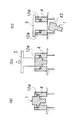
図2に、 本発明におけるシェービング加工の概略を模式的に示す。ゲート部12a を有するアーマチュア1を受け治具4に装入する。図2(a)は、アーマチュア1を受け治具4に装入した状態を示す断面図である。アーマチュア1は、ゲート部12a が受け治具4の段付き部に支持されて保持された状態とされる。
【0014】
ついで、受け治具4に押し治具5を嵌合し、油圧装置等により押し治具5を介しアーマチュア1を押し圧する。押し治具5によりアーマチュア1が押し圧された状態を図2(b)に示す。ゲート部12a は、受け治具4の段付き部に支持されているため、押し治具5によりアーマチュア1本体が押し圧されることにより、ゲート部12a に剪断力が付与される。押し治具5をさらに押し圧することにより、ゲート部12a が剪断破壊してすなわち、シェービング加工されて、アーマチュア1のプランジャー部から除去される。押し治具5に負荷される荷重は、ゲート部12a に剪断破壊が生じるに充分な荷重であればよい。
【0015】
図2(c)に、ゲート部12a が除去された状態を示す。ゲート部12a が除去されたアーマチュア1は、受け治具4の排出用孔43から排出される。
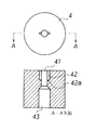
このアーマチュア1のシェービング加工に好適な受け治具4の一例を図3に示す。
受け治具4は、アーマチュア1が通過可能な貫通する孔部41を有す筒状治具である。この孔部41は、少なくともプランジャー部12が通過可能なように、アーマチュアのプランジャー部12の外径より大きい孔径を有する孔部である。なお、シェービング加工の精度向上のためには、孔部41の孔径をプランジャー部12の外径に略等しくすることが好ましい。なお、孔部41の孔径は、プランジャー部12の外周に残存するゲート部12a が通過できないように、プランジャー部外周に残存するゲート部を含めた外径より小さい、孔径とする。
【0016】
受け治具4には、図3に示すように、孔部41の入り側に溝状段付き部42が形成される。溝状段付き部42は、ゲート部12a を装入可能とする溝状で、かつアーマチュア1をゲート部12a で一時的に保持し、シェービング加工可能なように、段付き42a を有する。なお、溝状段付き部42の出側肩部、すなわち段付き42a の肩部、が鋭角に構成されることが好ましい。肩部を鋭角に構成することにより、シェービング加工の精度が向上する。
【0017】
受け治具4の孔部41に続く出側は、シェービング加工済みアーマチュア1の排出が容易なように、孔部41にくらべ大きい径を有する排出用孔43とすることが好ましい。なお、孔部41と排出用孔43とは、傾斜面で接続されるのが好ましいのはいうまでもない。
また、押し治具5は、上記した受け治具4の孔部41に嵌合可能でかつ押圧可能な先端部51を有することが好ましい。アーマチュア1のシェービング加工に好適な押し治具5の一例を図4に示す。
【0018】
図4では、先端部51の端面は、アーマチュア1のプランジャー部11の中空部13に嵌合可能な形状としている。アーマチュア1のプランジャー部の中空部13に嵌合可能な形状とすることにより、押圧時にアーマチュア1のプランジャー部の変形が少なく、アーマチュア1の寸法精度向上の観点からは好都合である。なお、押し治具5の先端部51の端部形状は、図4にしめされる形状に限定されるものではなく、受け治具4の孔部41に嵌合可能であれば端部を平坦としても何ら問題はない。
【0019】
つぎに、本発明におけるアーマチュア形状に、金属射出成形法により成形・焼結される焼結体の好ましい製造方法について説明する。焼結体は、混練造粒工程、射出成形工程、脱脂工程、および焼結工程をこの順に施されて製造される。
まず、原料粉末とバインダーとを混合し、混練し造粒する、混練造粒工程を施す。
【0020】
原料粉末としては、強磁性金属粉末とすることが好ましく、とくに、質量%で、C:0.15%、Ni:46.0〜48.0%、残部鉄および不可避的不純物からなる組成を有する合金鋼粉とすることが好ましい。また、電磁ステンレス鋼粉、パーマロイ粉としても何ら問題はない。
なお、本発明では、焼結体の密度を相対密度で95%以上の高密度とするために、使用する原料粉末を平均粒径20μm以下の球状アトマイズ粒とすることが好ましい。なお、より好ましくは、平均粒径5μm以下である。
【0021】
バインダーとしては、ポリエチレンにワックス、油類等を混合したもの、あるいはポリエチレンに分離のないワックスとを組み合わせたものが好適である。この場合、温度に対する影響が小さく、流動性に富む安定した混練物(金属原料粉末とバインダとの混合物)となる。
原料粉末とバインダーとの混練方法は、とくに限定する必要はないが、なかでも加圧ニーダを用いることが好ましい。混練は室温で、混練時間は約60min とすることが好ましい。混練後、冷却してから粉砕しペレット状とすることが好ましい。
【0022】
ついで、混練造粒工程を経てペレット状の混練物(コンパウンド)とされた原料粉末とバインダーは、射出成形工程を施される。射出成形工程では、コンパウンドを射出成形機により、射出成形用金型に射出し、所定形状のエレメント(射出成形材)に成形する。射出成形用金型は、予め15〜30℃に保持されることが好ましい。また、射出圧力は、1000〜2000kg/cm とすることが好ましい。
【0023】
得られたエレメント(射出成形材)は、ついで脱脂工程を施される。脱脂工程では、得られたエレメント(射出成形材)を溶剤中に浸漬し、バインダーを溶剤抽出するAMAX工法が用いることが好ましい。AMAX工法では、溶剤として、メチレンクロライドを用い、エレメント(射出成形材)を30±2℃に保持された溶剤中に3〜5h浸漬することが好ましい。
【0024】
脱脂工程を経たエレメント(射出成形材)は、ついで焼結工程を施され、焼結体とされる。焼結工程では、真空炉を用いて、1000〜1400℃の範囲の温度で行うことが好ましい。なお、加熱速度は 100〜 150℃/hとし、途中、650 ℃で2〜5h保持して所定の焼結温度まで加熱することが好ましい。なお、真空雰囲気は10-2〜10-3torr程度とすることが好ましい。
【0025】
上記した工程を経て得られた焼結体は、相対密度が95%以上の高密度で且つ空孔のうち独立空孔の占める割合が95%以上の焼結体となっているので燃料がアーマチュアの組織を通過して洩れることはない。
焼結体は、上記したようなシェービング加工により、ゲート部を除去されて製品(アーマチュア)とされる。本発明によるシェービング加工によりゲート部を除去することにより、アーマチュアのプランジャー部の外径の寸法精度は 0.1mm以下とすることができる。
【0026】
【実施例】
図1に示す形状のアーマチュア用の焼結体を金属射出成形法により作製した。使用した金属粉は、質量%で、C:0.15%以下、Ni:46.0〜48.0%を含み、残部鉄および不可避的不純物からなる組成の強磁性金属粉とした。これら金属粉に、バインダーとしてポリエチレンとワックス油と混合したものを用いて混合し、加圧ニーダで混練して混練物とした。ついで、 これら混練物を射出成形機から20℃に予熱した金型に、180Mpaの圧力で射出し、アーマチュア(射出成形材)とした。ついで、得られたアーマチュア(射出成形材)にAMAX工法による脱脂工程を施したのち、真空中の1280℃で3hの焼結工程を施し、焼結体とした。
【0027】
得られた焼結体は、0.3 mm高さのゲート部がアーマチュアのプランジャー部に残存していた。これらの焼結体を、図3に示す受け治具に装入し、図4に示す押し治具を使用して押し圧して、アーマチュアのプランジャー部に残存するゲート部を除去した。
得られたアーマチュアについて、プランジャー部の外径寸法の精度(ばらつき)を調査した。
【0028】
なお、比較例として、ゲート部の除去をヤスリによる切削作業により除去した。
この結果、本発明例では、安定して、ゲート部高さを 0.1mm以下に調整できる。また、比較例の単位時間内の生産量を100 とした場合に、本発明例では、200 と生産効率を顕著に向上させることができる。しかも製造されるアーマチュアの寸法精度は比較例にくらべ平均で80%以上向上した。
【0029】
【発明の効果】
本発明によれば、燃料噴射弁可動体用アーマチュアのプランジャー部外周に残存する、金属射出成形法特有のゲイト部を安定して精度良く除去でき、仕上寸法精度に優れたアーマチュアを安価に安定して製造でき、産業上格段の効果を奏する。
【図面の簡単な説明】
【図1】金属射出成形法により成形・焼結されたアーマチュアの形状の一例を示す断面模式図である。
【図2】本発明のアーマチュアの製造方法におけるシェービング加工方法を模式的に示す説明図である。
【図3】本発明に好適な受け治具の一例を示す模式図である。
【図4】本発明に好適な押し治具の一例を示す模式図である。
【符号の説明】
1 アーマチュア
2 横孔
3 球弁
4 受け治具
5 押し治具
11 ニードル部
12 プランジャー部
12a ゲート部
13 中空部
41 孔部
42 溝状段付き部
42a 段付き
43 排出用孔
51 先端部[0001]
BACKGROUND OF THE INVENTION
The present invention relates to a method of manufacturing an armature that constitutes a movable body of a fuel injection valve, and more particularly to improvement of finishing accuracy of the armature.
[0002]
[Prior art]
2. Description of the Related Art A fuel injection valve used in an internal combustion engine such as an automobile includes a movable body that moves by receiving a suction action by energization of a solenoid coil. The movable body is composed of an armature formed in a hollow shaft shape and a valve body that closes the distal end opening of the armature. Further, a lateral hole is formed on the side wall of the tip of the armature, and a fuel passage is formed in the movable body by the hollow portion and the lateral hole of the armature.
[0003]
Conventionally, this armature has been manufactured by forming a tubular material into a predetermined shape by forging and then forming a lateral hole in the side wall by cutting. However, such a manufacturing method has a problem in that the number of manufacturing processes is increased and productivity is not improved, and a process for removing burrs generated by the cutting process is required, which complicates the process and increases the manufacturing cost of the armature.
[0004]
For example, Japanese Patent Application Laid-Open No. 11-200979 proposes to use an armature molded by a metal injection molding method for the movable body of the fuel injection valve. By manufacturing the armature by metal injection molding, there is no need for cutting and deburring, and the manufacturing cost of the movable body can be reduced.
[0005]
[Problem to be Solved by the Invention]
However, in the armature of a fuel injection valve manufactured by the metal injection molding method used in the technique described in Japanese Patent Application Laid-Open No. 11-200979, a gate portion specific to the metal injection molding method is usually provided with a plunger of the armature. It remains in the part. Such a gate part is a kind of burr, and if the gate part remains convex in the subsequent grinding process, a cutting process for removing the gate is required, which causes a problem that the manufacturing cost increases. .
[0006]
The present invention advantageously solves the above-mentioned problems of the prior art, can stably and accurately remove the gate portion unique to the metal injection molding method remaining in the plunger portion of the armature, is inexpensive, and has excellent finish dimensional accuracy. The purpose is to propose a manufacturing method for the armature.
[0007]
[Means for Solving the Problems]
In order to achieve the above-described problems, the present inventors have earnestly studied a processing method that can stably and accurately remove the gate portion remaining on the plunger portion of the armature. As a result, it has been thought that removing the gate portion by applying a shaving process can manufacture an armature with high dimensional accuracy and stable and high productivity. Further, it has been found that the use of a special shaving jig is effective in improving the dimensional accuracy.
[0008]
The present invention has been completed with further studies based on these findings.
That is, in the present invention, the armature for the fuel injection valve movable body, which is a sintered body formed and sintered by the metal injection molding method, is inserted into the receiving jig, and then the pressing jig is inserted into the receiving jig. A method for manufacturing an armature characterized by removing a gate portion remaining on a plunger portion of the armature for a fuel injection valve movable body and sizing an outer periphery of the plunger portion by shaving processing to be fitted and pressed. . Further, in the present invention, the receiving jig is larger than the outer diameter of the plunger portion of the armature and smaller than the outer diameter including the gate portion remaining on the outer periphery of the plunger portion. A grooved step is provided that has a hole with a hole diameter that can pass through the gate part remaining on the outer periphery of the plunger part, and the gate part can be inserted and held on the entrance side of the hole part. It is preferable that the pressing jig has a tip that can be fitted into and pressed into the hole of the receiving jig. It is preferable that the grooved stepped portion is configured with an acute shoulder at the exit shoulder of the grooved stepped portion.
[0009]
Further, in the present invention, the sintered body preferably has a relative density of 95% or more, and the sintered body is a ratio of the independent pores in the pores formed in the sintered body. Is preferably 95% or more.
In the present invention, the sintered body is made of a ferromagnetic metal powder and has a composition comprising, by mass%, C: 0.15%, Ni: 46.0-48.0%, the balance iron and inevitable impurities. Furthermore, in the present invention, the sintered body is preferably made of electromagnetic stainless steel powder or permalloy powder.
[0010]
DETAILED DESCRIPTION OF THE INVENTION
The armature in the present invention is a component constituting a movable body used in a fuel injection valve used in an internal combustion engine such as an automobile, and is formed in a hollow shaft shape using a ferromagnetic material. The movable body is composed of this armature made of a ferromagnetic material and a ball valve that closes the distal end opening of the armature, and moves by receiving a suction action by energization of a solenoid coil.
[0011]
The armature in the present invention comprises a sintered body that is molded and sintered by a metal injection molding method. In the present invention, any generally known method can be applied as the metal injection molding method, and there is no particular limitation.
An example of a sectional shape of an armature that is a sintered body formed and sintered by a metal injection molding method is schematically shown in FIG.
[0012]
The armature 1 includes a
[0013]
In the present invention, the
In FIG. 2, the outline of the shaving process in this invention is shown typically. The armature 1 having the
[0014]
Next, the
[0015]
FIG. 2C shows a state where the
An example of a receiving
The receiving
[0016]
As shown in FIG. 3, a groove-shaped stepped
[0017]
The outlet side of the receiving
The pushing
[0018]
In FIG. 4, the end surface of the
[0019]
Next, a preferred method for producing a sintered body formed and sintered into the armature shape according to the present invention by a metal injection molding method will be described. The sintered body is manufactured by performing a kneading granulation step, an injection molding step, a degreasing step, and a sintering step in this order.
First, a raw material powder and a binder are mixed, kneaded and granulated, and subjected to a kneading granulation step.
[0020]
The raw material powder is preferably a ferromagnetic metal powder, and in particular, an alloy steel powder having a composition consisting of C: 0.15%, Ni: 46.0 to 48.0%, balance iron and inevitable impurities in mass%. Is preferred. Moreover, there is no problem as electromagnetic stainless steel powder and permalloy powder.
In the present invention, it is preferable that the raw material powder to be used is a spherical atomized particle having an average particle diameter of 20 μm or less in order to obtain a sintered body having a relative density of 95% or more. More preferably, the average particle size is 5 μm or less.
[0021]
As the binder, a mixture of polyethylene and wax, oil, or the like, or a combination of polyethylene and a non-separable wax is suitable. In this case, a stable kneaded product (mixture of metal raw material powder and binder) having a small influence on temperature and rich in fluidity is obtained.
The method for kneading the raw material powder and the binder is not particularly limited, but it is particularly preferable to use a pressure kneader. The kneading is preferably performed at room temperature and the kneading time is about 60 minutes. After kneading, it is preferable to cool and then pulverize into pellets.
[0022]
Next, the raw material powder and the binder that have been made into a pellet-like kneaded product (compound) through the kneading granulation step are subjected to an injection molding step. In the injection molding process, the compound is injected into an injection mold by an injection molding machine and formed into an element (injection molding material) having a predetermined shape. The injection mold is preferably held at 15 to 30 ° C. in advance. The injection pressure is preferably 1000 to 2000 kg /
[0023]
The obtained element (injection molding material) is then subjected to a degreasing process. In the degreasing step, it is preferable to use an AMAX method in which the obtained element (injection molding material) is immersed in a solvent and the binder is extracted with a solvent. In the AMAX method, methylene chloride is preferably used as a solvent, and the element (injection molding material) is preferably immersed for 3 to 5 hours in a solvent maintained at 30 ± 2 ° C.
[0024]
The element (injection molding material) that has undergone the degreasing process is then subjected to a sintering process to form a sintered body. The sintering step is preferably performed at a temperature in the range of 1000 to 1400 ° C. using a vacuum furnace. The heating rate is preferably 100 to 150 ° C./h, and is preferably heated to a predetermined sintering temperature while being held at 650 ° C. for 2 to 5 hours. The vacuum atmosphere is preferably about 10 −2 to 10 −3 torr.
[0025]
The sintered body obtained through the above-described process is a sintered body having a high density of 95% or more in relative density and a ratio of 95% or more of independent pores in the pores. There is no leakage through the tissue.
The sintered body is made into a product (armature) by removing the gate portion by the shaving process as described above. By removing the gate portion by shaving according to the present invention, the dimensional accuracy of the outer diameter of the plunger portion of the armature can be made 0.1 mm or less.
[0026]
【Example】
A sintered body for the armature having the shape shown in FIG. 1 was produced by a metal injection molding method. The metal powder used was a ferromagnetic metal powder having a composition comprising C: 0.15% or less, Ni: 46.0 to 48.0%, and the balance iron and unavoidable impurities. These metal powders were mixed using a mixture of polyethylene and wax oil as a binder, and kneaded with a pressure kneader to obtain a kneaded product. Next, these kneaded materials were injected from an injection molding machine into a mold preheated to 20 ° C. at a pressure of 180 Mpa to obtain an armature (injection molding material). Subsequently, the obtained armature (injection molding material) was subjected to a degreasing process by an AMAX method, and then subjected to a sintering process at 1280 ° C. in a vacuum for 3 hours to obtain a sintered body.
[0027]
In the obtained sintered body, the gate portion having a height of 0.3 mm remained on the plunger portion of the armature. These sintered bodies were inserted into a receiving jig shown in FIG. 3 and pressed using a pressing jig shown in FIG. 4 to remove the gate part remaining in the plunger part of the armature.
About the obtained armature, the precision (variation) of the outer diameter dimension of the plunger part was investigated.
[0028]
As a comparative example, the removal of the gate portion was removed by a cutting operation with a file.
As a result, in the example of the present invention, the height of the gate portion can be stably adjusted to 0.1 mm or less. Further, when the production amount in the unit time of the comparative example is set to 100, in the present invention example, the production efficiency can be remarkably improved to 200. Moreover, the dimensional accuracy of the manufactured armature was improved by 80% or more on average compared to the comparative example.
[0029]
【The invention's effect】
According to the present invention, it is possible to stably and accurately remove the gate portion peculiar to the metal injection molding method remaining on the outer periphery of the plunger portion of the armature for the fuel injection valve movable body, and to stably stabilize the armature having excellent finishing dimensional accuracy at low cost. Can be manufactured, and has a remarkable industrial effect.
[Brief description of the drawings]
FIG. 1 is a schematic cross-sectional view showing an example of the shape of an armature molded and sintered by a metal injection molding method.
FIG. 2 is an explanatory view schematically showing a shaving method in the armature manufacturing method of the present invention.
FIG. 3 is a schematic view showing an example of a receiving jig suitable for the present invention.
FIG. 4 is a schematic view showing an example of a pressing jig suitable for the present invention.
[Explanation of symbols]
1
11 Needle part
12 Plunger part
12a Gate part
13 Hollow part
41 hole
42 Grooved step
42a with steps
43 Drain hole
51 Tip
Claims (4)
Priority Applications (1)
| Application Number | Priority Date | Filing Date | Title |
|---|---|---|---|
| JP2001367287A JP3824524B2 (en) | 2001-11-30 | 2001-11-30 | Armature manufacturing method |
Applications Claiming Priority (1)
| Application Number | Priority Date | Filing Date | Title |
|---|---|---|---|
| JP2001367287A JP3824524B2 (en) | 2001-11-30 | 2001-11-30 | Armature manufacturing method |
Publications (2)
| Publication Number | Publication Date |
|---|---|
| JP2003166454A JP2003166454A (en) | 2003-06-13 |
| JP3824524B2 true JP3824524B2 (en) | 2006-09-20 |
Family
ID=19177059
Family Applications (1)
| Application Number | Title | Priority Date | Filing Date |
|---|---|---|---|
| JP2001367287A Expired - Fee Related JP3824524B2 (en) | 2001-11-30 | 2001-11-30 | Armature manufacturing method |
Country Status (1)
| Country | Link |
|---|---|
| JP (1) | JP3824524B2 (en) |
Families Citing this family (2)
| Publication number | Priority date | Publication date | Assignee | Title |
|---|---|---|---|---|
| JP2010203375A (en) * | 2009-03-04 | 2010-09-16 | Denso Corp | Fuel injection valve |
| FR3084772B1 (en) * | 2018-08-01 | 2021-06-18 | Schneider Electric Ind Sas | ELECTROMAGNETIC ACTUATOR AND ELECTRICAL SWITCHING APPARATUS INCLUDING THIS ACTUATOR |
-
2001
- 2001-11-30 JP JP2001367287A patent/JP3824524B2/en not_active Expired - Fee Related
Also Published As
| Publication number | Publication date |
|---|---|
| JP2003166454A (en) | 2003-06-13 |
Similar Documents
| Publication | Publication Date | Title |
|---|---|---|
| KR101632853B1 (en) | Rare-earth-magnet production method | |
| WO1999056898A1 (en) | Process for producing sintered product | |
| WO2001072456A1 (en) | Method for manufacturing metal parts | |
| CN107134336A (en) | R T B systems permanent magnet | |
| CN106111994B (en) | Use the method for ferrous metal nodular powder manufacture ferrous metal part | |
| JP3824524B2 (en) | Armature manufacturing method | |
| US6537487B1 (en) | Method of manufacturing form tools for forming threaded fasteners | |
| JP2009299106A (en) | Method for producing composite sintered compact, and composite sintered compact | |
| US20020131886A1 (en) | Method of manufacturing an object, such as a form tool for forming threaded fasteners | |
| US20040146424A1 (en) | Production of component parts by metal injection moulding (mim) | |
| US6770114B2 (en) | Densified sintered powder and method | |
| KR20110099708A (en) | Pre-product for the production of sintered metallic components, a method for producing the pre-product and the production of components | |
| JP3687143B2 (en) | Burr treatment method for metal powder injection molded body | |
| JP2002235865A (en) | Solenoid core of solenoid valve and its manufacturing method | |
| JP2019151910A (en) | Method for producing composite sintered member and composite sintered member | |
| CN114086015B (en) | Copper-tungsten alloy part and manufacturing method thereof | |
| JPH07126712A (en) | Deburring method of injection molded goods of metallic powder goods | |
| JP3763796B2 (en) | Manufacturing method of sintered member with inner hole with excellent coaxiality accuracy | |
| JPH0353002A (en) | Manufacture of sintered cam | |
| JP2009167482A (en) | Method for producing connecting rod, and connecting rod | |
| JPH03290906A (en) | Warm-worked magnet and its manufacture | |
| JP2005272934A (en) | Method for manufacturing metal member using fine atomized metal powder, and metal member using fine atomized metal powder | |
| JP2681801B2 (en) | Method for producing injection molding raw material containing metal powder | |
| JP2000199001A (en) | Powder and method for manufacturing high density sintered body | |
| Chang et al. | Fabrication of micro metal parts by forging process combined with powder pressing |
Legal Events
| Date | Code | Title | Description |
|---|---|---|---|
| A621 | Written request for application examination |
Free format text: JAPANESE INTERMEDIATE CODE: A621 Effective date: 20040317 |
|
| TRDD | Decision of grant or rejection written | ||
| A01 | Written decision to grant a patent or to grant a registration (utility model) |
Free format text: JAPANESE INTERMEDIATE CODE: A01 Effective date: 20060627 |
|
| A61 | First payment of annual fees (during grant procedure) |
Free format text: JAPANESE INTERMEDIATE CODE: A61 Effective date: 20060627 |
|
| R150 | Certificate of patent or registration of utility model |
Free format text: JAPANESE INTERMEDIATE CODE: R150 Ref document number: 3824524 Country of ref document: JP Free format text: JAPANESE INTERMEDIATE CODE: R150 |
|
| FPAY | Renewal fee payment (event date is renewal date of database) |
Free format text: PAYMENT UNTIL: 20090707 Year of fee payment: 3 |
|
| FPAY | Renewal fee payment (event date is renewal date of database) |
Free format text: PAYMENT UNTIL: 20100707 Year of fee payment: 4 |
|
| FPAY | Renewal fee payment (event date is renewal date of database) |
Free format text: PAYMENT UNTIL: 20110707 Year of fee payment: 5 |
|
| FPAY | Renewal fee payment (event date is renewal date of database) |
Free format text: PAYMENT UNTIL: 20110707 Year of fee payment: 5 |
|
| FPAY | Renewal fee payment (event date is renewal date of database) |
Free format text: PAYMENT UNTIL: 20120707 Year of fee payment: 6 |
|
| FPAY | Renewal fee payment (event date is renewal date of database) |
Free format text: PAYMENT UNTIL: 20120707 Year of fee payment: 6 |
|
| FPAY | Renewal fee payment (event date is renewal date of database) |
Free format text: PAYMENT UNTIL: 20130707 Year of fee payment: 7 |
|
| LAPS | Cancellation because of no payment of annual fees |