JP3824010B1 - refrigerator - Google Patents

refrigerator Download PDF

Info

Publication number
JP3824010B1
JP3824010B1 JP2005182075A JP2005182075A JP3824010B1 JP 3824010 B1 JP3824010 B1 JP 3824010B1 JP 2005182075 A JP2005182075 A JP 2005182075A JP 2005182075 A JP2005182075 A JP 2005182075A JP 3824010 B1 JP3824010 B1 JP 3824010B1
Authority
JP
Japan
Prior art keywords
machine room
compressor
refrigerator according
box
refrigerator
Prior art date
Legal status (The legal status is an assumption and is not a legal conclusion. Google has not performed a legal analysis and makes no representation as to the accuracy of the status listed.)
Active
Application number
JP2005182075A
Other languages
Japanese (ja)
Other versions
JP2007003067A (en
Inventor
忠弘 川村
祥記 大橋
Current Assignee (The listed assignees may be inaccurate. Google has not performed a legal analysis and makes no representation or warranty as to the accuracy of the list.)
Panasonic Corp
Panasonic Holdings Corp
Original Assignee
Panasonic Corp
Matsushita Electric Industrial Co Ltd
Priority date (The priority date is an assumption and is not a legal conclusion. Google has not performed a legal analysis and makes no representation as to the accuracy of the date listed.)
Filing date
Publication date
Application filed by Panasonic Corp, Matsushita Electric Industrial Co Ltd filed Critical Panasonic Corp
Priority to JP2005182075A priority Critical patent/JP3824010B1/en
Priority to CN2006800116270A priority patent/CN101156035B/en
Priority to PCT/JP2006/312379 priority patent/WO2006137422A1/en
Priority to TW095122338A priority patent/TW200710357A/en
Application granted granted Critical
Publication of JP3824010B1 publication Critical patent/JP3824010B1/en
Publication of JP2007003067A publication Critical patent/JP2007003067A/en
Active legal-status Critical Current
Anticipated expiration legal-status Critical

Links

Images

Classifications

    • FMECHANICAL ENGINEERING; LIGHTING; HEATING; WEAPONS; BLASTING
    • F25REFRIGERATION OR COOLING; COMBINED HEATING AND REFRIGERATION SYSTEMS; HEAT PUMP SYSTEMS; MANUFACTURE OR STORAGE OF ICE; LIQUEFACTION SOLIDIFICATION OF GASES
    • F25DREFRIGERATORS; COLD ROOMS; ICE-BOXES; COOLING OR FREEZING APPARATUS NOT OTHERWISE PROVIDED FOR
    • F25D23/00General constructional features
    • F25D23/003General constructional features for cooling refrigerating machinery
    • FMECHANICAL ENGINEERING; LIGHTING; HEATING; WEAPONS; BLASTING
    • F25REFRIGERATION OR COOLING; COMBINED HEATING AND REFRIGERATION SYSTEMS; HEAT PUMP SYSTEMS; MANUFACTURE OR STORAGE OF ICE; LIQUEFACTION SOLIDIFICATION OF GASES
    • F25BREFRIGERATION MACHINES, PLANTS OR SYSTEMS; COMBINED HEATING AND REFRIGERATION SYSTEMS; HEAT PUMP SYSTEMS
    • F25B2500/00Problems to be solved
    • F25B2500/13Vibrations
    • FMECHANICAL ENGINEERING; LIGHTING; HEATING; WEAPONS; BLASTING
    • F25REFRIGERATION OR COOLING; COMBINED HEATING AND REFRIGERATION SYSTEMS; HEAT PUMP SYSTEMS; MANUFACTURE OR STORAGE OF ICE; LIQUEFACTION SOLIDIFICATION OF GASES
    • F25DREFRIGERATORS; COLD ROOMS; ICE-BOXES; COOLING OR FREEZING APPARATUS NOT OTHERWISE PROVIDED FOR
    • F25D2323/00General constructional features not provided for in other groups of this subclass
    • F25D2323/002Details for cooling refrigerating machinery
    • F25D2323/0026Details for cooling refrigerating machinery characterised by the incoming air flow
    • F25D2323/00268Details for cooling refrigerating machinery characterised by the incoming air flow through the top
    • FMECHANICAL ENGINEERING; LIGHTING; HEATING; WEAPONS; BLASTING
    • F25REFRIGERATION OR COOLING; COMBINED HEATING AND REFRIGERATION SYSTEMS; HEAT PUMP SYSTEMS; MANUFACTURE OR STORAGE OF ICE; LIQUEFACTION SOLIDIFICATION OF GASES
    • F25DREFRIGERATORS; COLD ROOMS; ICE-BOXES; COOLING OR FREEZING APPARATUS NOT OTHERWISE PROVIDED FOR
    • F25D2323/00General constructional features not provided for in other groups of this subclass
    • F25D2323/002Details for cooling refrigerating machinery
    • F25D2323/0027Details for cooling refrigerating machinery characterised by the out-flowing air
    • F25D2323/00272Details for cooling refrigerating machinery characterised by the out-flowing air from the back top

Landscapes

  • Engineering & Computer Science (AREA)
  • Chemical & Material Sciences (AREA)
  • Combustion & Propulsion (AREA)
  • Physics & Mathematics (AREA)
  • Mechanical Engineering (AREA)
  • Thermal Sciences (AREA)
  • General Engineering & Computer Science (AREA)
  • Refrigerator Housings (AREA)

Abstract

【課題】圧縮機を本体上部に設置する冷蔵庫において、組み立て精度,生産効率が高く、音源から発生する騒音の抑制と、振動の伝播を抑制した冷蔵庫を提供する。
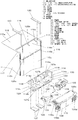
【解決手段】外箱115の機械室113が対応する部分に切り欠き部116を設け、切り欠き部116に樹脂で形成した機械室の外郭114を係合させ、この機械室の外郭114上に圧縮機122,凝縮器123、強制冷却用の送風機128等を載置したものであり、圧縮機122等を収容する異形で複雑な形状の機械室部分を樹脂成形で別途一体に形成することができ、作業性の向上と組み立て精度の向上が図れる。また、鋼板製の外箱115に対して材質の異なる樹脂成形の機械室の外郭114を接合することによって圧縮機122,送風機128の騒音,振動が冷蔵庫本体101への伝播するのを抑制することができる。
【選択図】図1
In a refrigerator in which a compressor is installed at the upper part of a main body, an assembly accuracy and production efficiency are high, and a refrigerator in which noise generated from a sound source is suppressed and propagation of vibration is suppressed is provided.
A notch 116 is provided in a portion corresponding to a machine chamber 113 of an outer box 115, and an outer shell 114 made of resin is engaged with the notch 116, and the outer shell 114 of the machine chamber is engaged with the notch. A compressor 122, a condenser 123, a blower 128 for forced cooling, and the like are mounted, and a deformed and complex machine room portion that accommodates the compressor 122 and the like may be separately formed integrally by resin molding. It is possible to improve workability and assembly accuracy. Further, by joining the outer casing 114 of a resin-molded machine room made of a different material to the outer casing 115 made of steel plate, it is possible to suppress the noise and vibration of the compressor 122 and the blower 128 from propagating to the refrigerator main body 101. Can do.
[Selection] Figure 1

Description

本発明は圧縮機を天面部に載置した冷蔵庫に関するものである。   The present invention relates to a refrigerator in which a compressor is placed on the top surface.

近年、冷蔵庫は地球環境保護の観点から更なる省エネルギー化が進むとともに、その使い勝手や収納性の向上が求められている。   In recent years, refrigerators are required to be further energy-saving from the viewpoint of protecting the global environment, and to be improved in usability and storage.

従来この種の冷蔵庫は、最下部に配設された貯蔵室の収納容積の拡大を図る目的のために、断熱箱体の貯蔵室内最上部の後背部が下がるように窪ませた凹部を設け、その凹部に冷凍サイクルの構成機器を収納するという方法がとられていた(例えば、特許文献1参照)。   Conventionally, this type of refrigerator is provided with a recess recessed so that the back of the uppermost storage chamber of the heat insulation box is lowered for the purpose of enlarging the storage volume of the storage chamber disposed at the bottom, The method of accommodating the component apparatus of a refrigerating cycle in the recessed part was taken (for example, refer patent document 1).

図8は、従来の冷蔵庫の断面図である。図9は従来の冷蔵庫を後方より見た要部斜視図である。   FIG. 8 is a cross-sectional view of a conventional refrigerator. FIG. 9 is a perspective view of main parts of a conventional refrigerator as viewed from the rear.

図に示すように、断熱箱体1の外壁を形成する一般的には鋼板製の外箱2と、断熱箱体1の庫内壁を形成する一般的には樹脂製の内箱3と、外箱2と内箱3の間に発泡充填させた発泡ウレタン断熱材4からなり、上から順に、冷蔵室5、冷凍室6、野菜室7を有し、冷蔵室5の前面開口には、冷蔵室回転扉8を設けている。また、断熱箱体1の中央から下方部に位置する冷凍室6と野菜室7は収納性と使い勝手を考慮して、簡易に取り出しが行える引き出しタイプの冷凍室引き出し扉9と野菜室引き出し扉12を設けてある。   As shown in the figure, an outer wall 2 generally made of steel plate that forms the outer wall of the heat insulating box 1, an inner box 3 generally made of resin that forms the inner wall of the heat insulating box 1, and the outer It is made of urethane foam heat insulating material 4 which is foam-filled between the box 2 and the inner box 3, and has a refrigerator room 5, a freezer room 6, and a vegetable room 7 in order from the top. A chamber revolving door 8 is provided. In addition, the freezer compartment 6 and the vegetable compartment 7 located in the lower part from the center of the heat insulating box 1 are a drawer-type freezer compartment drawer door 9 and a vegetable compartment drawer door 12 that can be easily taken out in consideration of storability and convenience. Is provided.

断熱箱体1に設けた凹部20は、外箱上面21と外箱背面22に渡る天面後背部を冷蔵室5の最上部の後背部が下がるように凹ませた箇所である。凹部20はその左右が断熱箱体1の左右壁23,24にて塞がれ上方および背方に開放しており、この凹部20の開放部は、上板25とこれにほぼ直角な背板26とからなる凹部カバー27にて覆われている。また、凹部カバー25はネジなどにて外箱2の鋼板に取外し可能に固定されている。   The recessed part 20 provided in the heat insulation box 1 is the part which dented the top back part over the outer box upper surface 21 and the outer box back surface 22 so that the uppermost back part of the refrigerator compartment 5 might fall. The left and right sides of the recess 20 are closed by the left and right walls 23 and 24 of the heat insulation box 1 and open upward and to the back. The open portion of the recess 20 is an upper plate 25 and a back plate substantially perpendicular to the upper plate 25. 26 is covered with a concave portion cover 27. The recess cover 25 is detachably fixed to the steel plate of the outer box 2 with screws or the like.

冷凍サイクルの構成機器である圧縮機31と凝縮器32は共に凹部20内に収まるように配設され、凝縮器32の前面に対向して設けられた凝縮器冷却用の機械室ファン33と併せて凹部カバー27にて覆われている。   The compressor 31 and the condenser 32, which are components of the refrigeration cycle, are both arranged so as to be accommodated in the recess 20, and are combined with a machine room fan 33 for cooling the condenser provided facing the front surface of the condenser 32. And is covered with a recess cover 27.

また、圧縮機31は弾性部材等を介して凹部20内の底壁に直接支持され載置されており、機械室ファン33も凹部20内の前壁に直接支持されている。   The compressor 31 is directly supported and placed on the bottom wall in the recess 20 via an elastic member or the like, and the machine room fan 33 is also directly supported on the front wall in the recess 20.

また、凹部カバー27の上板25と背板26には、放熱のために複数の通気口34,35がそれぞれ設けられており、その配置構成から、上板25に開口した通気口34を吸気口とし、背板26に開口した通気口35を排気口としている。   In addition, the upper plate 25 and the back plate 26 of the recess cover 27 are provided with a plurality of vent holes 34 and 35 for heat dissipation, respectively, and from the arrangement configuration, the vent holes 34 opened in the upper plate 25 are sucked. A vent hole 35 opened in the back plate 26 is used as an exhaust port.

また、冷凍サイクルの構成機器である蒸発器36は冷凍室6の後背部に冷却ファン37と共に配設されており、最下部の貯蔵室である野菜室7は奥行き深く構成してある。   The evaporator 36, which is a component device of the refrigeration cycle, is disposed with a cooling fan 37 at the back of the freezer compartment 6, and the vegetable compartment 7, which is the lowest storage compartment, is configured deeply.

これにより、断熱箱体1の背面下部に圧縮機31や凝縮器32を収納するものと比較して、野菜室7の内容積を大きく、深く構成できる。また、高圧機器を断熱箱体1の上部に配置しても、使用者の手が届きにくくて使いにくいために敬遠される天面後背部のスペースに高圧機器の収容部となる凹部20を設けているため、最上部の貯蔵室である冷蔵室5の使い勝手を実質的に損ねることがないものである。
特開2001−99552号公報
Thereby, compared with what stores the compressor 31 and the condenser 32 in the back lower part of the heat insulation box 1, the internal volume of the vegetable compartment 7 can be enlarged and comprised deeply. In addition, even when the high-voltage device is arranged on the upper portion of the heat insulation box 1, a recess 20 is provided in the space behind the top surface that is difficult to use because it is difficult for the user to reach and is used to house the high-voltage device. Therefore, the usability of the refrigerator compartment 5 which is the uppermost storage room is not substantially impaired.
JP 2001-99552 A

しかしながら、上記従来の構成では、断熱箱体1を直接凹ませて凹部20を形成しているため、圧縮機31などの比較的外形の大きな高圧機器等を収容する関係上、凹部20の両側部に左右壁23,24を有する場合は特に、外箱上面21と外箱背面22の鋼板を一体絞り加工したり、外箱上面21と外箱背面22の鋼板を折曲加工して接合したりする製造上相当に困難であり、作業性が悪く製造コストもかさむという問題点があった。   However, in the above-described conventional configuration, since the recessed portion 20 is formed by directly denting the heat insulating box 1, both sides of the recessed portion 20 are accommodated in order to accommodate a high-pressure device having a relatively large outer shape such as the compressor 31. In particular, when the left and right walls 23 and 24 are provided, the steel plate of the outer case upper surface 21 and the outer case rear surface 22 is integrally drawn, or the outer case upper surface 21 and the outer case rear surface 22 are bent and joined. However, there is a problem in that it is considerably difficult to manufacture and the workability is poor and the manufacturing cost is increased.

また、凹部20の内壁が断熱箱体の外箱2の表面となるため、騒音,振動発生源である圧縮機31や機械室ファン33を外箱2に直接支持する構成となり、これらの騒音,振動は、凹部20を介し冷蔵室5等の庫内へ透過する。特に使用者が冷蔵庫回転扉8を開けた場合に、冷蔵庫正面側へ漏れやすく、その結果、騒音,振動発生源である圧縮機31,機械室ファン33が高さ的に人間の耳の高さに近い箇所にあるため、騒音が気になったり、扉開閉時等にヒンジ機構で断熱箱体1に枢支される冷蔵庫回転扉8に触れた場合に振動が伝わりやすく、冷蔵庫本体が共振して他の部品(例えば、冷蔵室5内の食品収納棚)へ伝播し、その部品が振動することによる共振音が発生する、という問題点があった。   Further, since the inner wall of the recess 20 becomes the surface of the outer box 2 of the heat insulating box, the compressor 31 and the machine room fan 33, which are noise and vibration sources, are directly supported on the outer box 2, and these noises, The vibration is transmitted into the refrigerator compartment 5 and the like through the recess 20. In particular, when the user opens the refrigerator revolving door 8, it easily leaks to the front side of the refrigerator, and as a result, the compressor 31 and the machine room fan 33, which are noise and vibration sources, are taller than the human ear. Therefore, when the door is opened or closed, vibrations are easily transmitted when touching the refrigerator revolving door 8 pivotally supported by the heat insulating box 1 by a hinge mechanism when the door is opened or closed. In other words, there is a problem in that a resonance sound is generated due to vibration transmitted to another part (for example, a food storage shelf in the refrigerator compartment 5).

さらには、凹部20内への圧縮機31,凝縮器32,機械室ファン33等の収容部品の取り付けを凹部20の内壁面に直接行うことになるため、部品の位置決めなどを含めて作業性が悪く、取り付けばらつきが生じやすくなって騒音,振動を助長する原因にもなる、という問題点もあった。   Furthermore, since the housing parts such as the compressor 31, the condenser 32, and the machine room fan 33 are directly attached to the concave wall 20, the workability including positioning of the parts is improved. Unfortunately, there was also a problem that mounting variation was likely to occur, and this also contributed to noise and vibration.

また、断熱箱体のフレームは、例えば0.5mm程度の鋼板製の外箱2と2mm程度の薄肉ABSでできた内箱3及びで内部の発泡ウレタン断熱材4を覆う3層構造となるが、断熱箱体1の上部は凹部20により矩形形状ではなく異形となるため、強度が不十分であった。   Further, the frame of the heat insulation box has a three-layer structure that covers, for example, the outer box 2 made of a steel plate of about 0.5 mm and the inner box 3 made of thin ABS of about 2 mm and the urethane foam heat insulating material 4 inside. The upper part of the heat insulating box 1 is not rectangular because of the concave portion 20, but has an insufficient shape.

したがって、圧縮機311および機械室ファン33が動作する時、これらによる振動が断熱箱体1に直接的に伝播すると、共振音がさらに大きくなる懸念があった。   Therefore, when the compressor 311 and the machine room fan 33 are operated, there is a concern that if the vibration caused by these propagates directly to the heat insulating box 1, the resonance noise further increases.

また、凹部20の周辺強度が不十分であると、冷蔵庫本体の運搬時に必要な取っ手の取り付け強度が不十分となり、運搬時の安全性を確保することが容易ではない、という問題点があった。   In addition, if the peripheral strength of the recess 20 is insufficient, there is a problem that the handle mounting strength necessary for transporting the refrigerator body becomes insufficient, and it is not easy to ensure safety during transport. .

また、凹部20内での凝縮器32と機械室ファン33の配置関係と吸気用の通気口34と,排気用の通気口35の配置関係が、凹部20の奥行き方向に並べられているため、凹部20内のスペースが有効に活用されておらず、機械室ファン33による圧縮機31の冷却効果も含めて凹部20内の放熱効率が十分に高められない構成であり、凹部20内の温度上昇により冷蔵室5内への熱漏洩による省エネルギー面での影響が生じる懸念があった。   Further, since the arrangement relationship between the condenser 32 and the machine room fan 33 in the recess 20 and the arrangement relationship between the intake vent 34 and the exhaust vent 35 are arranged in the depth direction of the recess 20, The space in the recess 20 is not effectively utilized, and the heat dissipation efficiency in the recess 20 including the cooling effect of the compressor 31 by the machine room fan 33 cannot be sufficiently increased. Therefore, there is a concern that an energy saving effect due to heat leakage into the refrigerator compartment 5 occurs.

また、凹部20内に収容した圧縮機31,凝縮器32に冷凍サイクルの冷媒配管を接続する際には、外箱上面21と外箱背面22の鋼板を貫通して冷媒配管を配設しなければならず、貫通部における冷媒配管の支持固定やシール性が不十分なものになり、冷媒配管の折れ等の損傷や発泡ウレタン断熱材4の漏れ等が生じる問題点があった。   In addition, when connecting the refrigerant piping of the refrigeration cycle to the compressor 31 and the condenser 32 housed in the recess 20, the refrigerant piping must be provided through the steel plates of the outer case upper surface 21 and the outer case rear surface 22. In other words, the support and fixing of the refrigerant pipe at the penetrating portion and the sealing performance are insufficient, causing problems such as breakage of the refrigerant pipe and leakage of the urethane foam heat insulating material 4.

本発明は、上記従来の課題を解決するもので、圧縮機を断熱箱体の天面部に凹部を設けて設置する冷蔵庫において、圧縮機を収容する凹部の組み立ての簡素化と精度の向上を通じて構造強度の向上を図り、騒音,振動の伝播を抑制するとともに、省エネルギー化にも寄与する冷蔵庫を提供することを目的とする。   The present invention solves the above-described conventional problems, and in a refrigerator in which a compressor is installed by providing a recess in the top surface portion of a heat insulating box, the structure is provided through simplification of assembly of the recess to accommodate the compressor and improvement of accuracy. An object is to provide a refrigerator that improves the strength, suppresses the propagation of noise and vibration, and contributes to energy saving.

上記従来の課題を解決するために、本発明の冷蔵庫は、外箱と内箱と前記外箱と前記内箱との間に設けた断熱材とよりなる断熱箱体と、前記断熱箱体の天面後方を庫内側に凹ませて形成した機械室と、前記機械室内に収容した冷凍サイクルの圧縮機とを有し、前記外箱を金属板で形成し、前記圧縮機を載置する前記機械室の外郭を樹脂で形成したものであって、前記外箱の前記機械室が対応する部分に切り欠き部が設けられ、前記切り欠き部に前記機械室の樹脂で形成した前記外郭を係合させ、前記内箱と金属板で形成した前記外箱と前記機械室の樹脂で形成した前記外郭との空間に発泡断熱材を充填して前記断熱箱体を接合形成し、前記発泡断熱材と接合する前記機械室の樹脂で形成した前記外郭上に前記圧縮機を載置したものである。 In order to solve the above-described conventional problems, the refrigerator of the present invention includes an outer box, an inner box, a heat insulating box formed of a heat insulating material provided between the outer box and the inner box, and the heat insulating box body. A machine room formed by recessing the rear of the top surface inside the cabinet, and a compressor of a refrigeration cycle housed in the machine room, the outer box is formed of a metal plate, and the compressor is placed thereon The outer shell of the machine room is formed of resin, and a notch is provided in a portion corresponding to the machine chamber of the outer box, and the outer shell formed of the resin of the machine chamber is engaged with the notch. And filling the space between the outer box formed of the inner box and the metal plate and the outer wall formed of the resin of the machine room with the foamed heat insulating material to join and form the heat insulating box body. The compressor is placed on the outer shell formed of resin in the machine room to be joined to the machine .

これによって、圧縮機を収容する異形で複雑な形状の機械室部分を樹脂成形で別途一体に形成することができ、機械室の組み立て工程において簡素化による作業性の向上と組み立て精度の向上が図れる。また、機械室外郭の樹脂成形における補強構造や外箱との接合構造を適切なものとすることにより剛性が高くなり、かつ鋼板に代表される金属板製の外箱と材質の異なる樹脂成形の機械室外郭を接合することによって圧縮機の騒音,振動が冷蔵庫本体への伝播するのを抑制することができる。   This makes it possible to separately form a deformed and complex machine room portion that accommodates the compressor by resin molding, and to improve workability and assembly accuracy by simplifying the assembly process of the machine room. . In addition, by making the reinforcement structure in the resin molding of the machine room outer shell and the joining structure with the outer box appropriate, the rigidity is increased, and the resin molding of a material different from the metal box outer box represented by the steel plate is used. By joining the machine room outline, it is possible to suppress the noise and vibration of the compressor from propagating to the refrigerator body.

本発明の冷蔵庫は、圧縮機を収容する機械室を冷蔵庫本体の天面部に形成した冷蔵庫において、機械室の組み立て作業性と組み立て精度の向上が図れ、圧縮機上部配置型の冷蔵庫を高い品質で合理的に提供することができる。また、機械室外郭の剛性が高くなり、圧縮機の騒音,振動の伝播を抑制し、庫内部品の共振音の発生等も防止して使用者や居住者の不快感を拭うことができる。   The refrigerator of the present invention is a refrigerator in which a machine room for accommodating a compressor is formed on the top surface of the refrigerator body. As a result, the assembly workability and the assembly accuracy of the machine room can be improved, and the compressor upper arrangement type refrigerator is of high quality. Can be provided reasonably. Moreover, the rigidity of the machine room outer shell is increased, the noise of the compressor and the propagation of vibration are suppressed, the generation of resonance noise of the internal parts is prevented, and the uncomfortable feeling of the user and the resident can be wiped off.

請求項1に記載の発明は、外箱と内箱と前記外箱と前記内箱との間に設けた断熱材とよりなる断熱箱体と、前記断熱箱体の天面後方を庫内側に凹ませて形成した機械室と、前記機械室内に収容した冷凍サイクルの圧縮機とを有し、前記外箱を金属板で形成し、前記圧縮機を載置する前記機械室の外郭を樹脂で形成したものであって、前記外箱の前記機械室が対応する部分に切り欠き部が設けられ、前記切り欠き部に前記機械室の樹脂で形成した前記外郭を係合させ、前記内箱と金属板で形成した前記外箱と前記機械室の樹脂で形成した前記外郭との空間に発泡断熱材を充填して前記断熱箱体を接合形成し、前記発泡断熱材と接合する前記機械室の樹脂で形成した前記外郭上に前記圧縮機を載置したものであり、圧縮機を収容する異形で複雑な形状の機械室部分を樹脂成形で別途一体に形成することができ、機械室の組み立て工程において簡素化による作業性の向上と組み立て精度の向上が図れ、製造コストを抑えて、圧縮機上部配置型の冷蔵庫を高い品質で合理的に提供することができる。
また、予め外箱の機械室相当部分を切り欠いておくことによって、機械室相当部分の異形で複雑な形状を外箱で形成する必要がなく、鈑金工程の難易度が抑えられて簡素化され、金属板である鋼板も高価な深絞り材等を用いる必要がなく合理的に筐体を形成できる。
The invention according to claim 1 is a heat insulating box body including an outer box, an inner box, a heat insulating material provided between the outer box and the inner box, and a top rear of the heat insulating box body on the inner side. A machine room formed by recessing and a compressor of a refrigeration cycle housed in the machine room, the outer box is formed of a metal plate, and the outer wall of the machine room on which the compressor is placed is made of resin. A notch is provided in a portion corresponding to the machine chamber of the outer box, and the outer shell formed of resin in the machine chamber is engaged with the notch, and the inner box and Filling the space between the outer box formed of a metal plate and the outer shell formed of resin in the machine room with a foam heat insulating material to form the heat insulating box body, and joining the foam heat insulating material to the machine room It is obtained by mounting the compressor on the outer formed of resin, complicated in variant for accommodating a compressor Can be formed separately by resin molding, improving the workability and assembly accuracy by simplifying the assembly process of the machine room, reducing the manufacturing cost, and placing the compressor on top The refrigerator can be reasonably provided with high quality.
In addition, by cutting out the part corresponding to the machine room of the outer box in advance, it is not necessary to form an irregular and complicated shape of the part corresponding to the machine room with the outer box, and the difficulty of the plating process is suppressed and simplified. The steel plate, which is a metal plate, can be formed rationally without the need to use an expensive deep drawing material or the like.

また、機械室外郭の樹脂成形における補強構造や外箱との接合構造を適切なものとすることにより剛性が高くなり、かつ鋼板に代表される金属板製の外箱と材質の異なる樹脂成形の機械室外郭を接合することによって振動伝播が減衰し、圧縮機の騒音,振動が冷蔵庫本体への伝播することが抑制され、庫内部品の共振音の発生等も防止できて、人の耳障りになりやすい配置となる圧縮機上部配置型の冷蔵庫においても使用者や居住者の不快感を拭うことができる。   In addition, by making the reinforcement structure in the resin molding of the machine room outer shell and the joining structure with the outer box appropriate, the rigidity is increased, and the resin molding of a material different from the metal box outer box represented by the steel plate is used. By joining the machine room shell, the vibration propagation is attenuated, the compressor noise and vibration are prevented from propagating to the refrigerator body, and the generation of resonance noise of the internal parts can be prevented, which can be detrimental to humans. Even in the compressor upper arrangement type refrigerator that is easily arranged, the discomfort of the user or resident can be wiped off.

また、機械室外郭を別途樹脂で一体成型して冷蔵庫本体の外箱と接合する構成を採用することによって、製造工程においては冷蔵庫の外形の異なる製品間でも機械室部分の共用化や標準化を図れる可能性を有するものである。   In addition, by adopting a structure in which the outer casing of the machine room is integrally molded with resin and joined to the outer box of the refrigerator body, the machine room can be shared and standardized between products with different external shapes in the manufacturing process. It has a possibility.

また、製造工程の工夫によっては、樹脂成形された機械室外郭に圧縮機をはじめとした各部品を予め装着して予備的に組み立てておき、この機械室の予備組み立て品を冷蔵庫本体の外箱に装着して接合させ、冷媒配管等を連結するなどの方法も考えられ、製造工程の一層の合理化による生産性の向上や予備組み立て品としての共用化、標準化を取り入れることによる製造コストの低減が図れる。   In addition, depending on the contrivance of the manufacturing process, parts such as a compressor are preliminarily assembled and pre-assembled on the resin-molded machine room outline, and this machine room pre-assembled product is attached to the outer box of the refrigerator main body. It is also conceivable to attach and join to refrigerant pipes and connect refrigerant pipes, etc., improving productivity by further streamlining the manufacturing process, sharing it as a pre-assembly, and reducing manufacturing costs by incorporating standardization I can plan.

請求項2に記載の発明は、請求項1に記載に発明において、前記機械室内に前記圧縮機を強制冷却する送風機をさらに収容し、前記送風機を樹脂で形成された機械室の前記外郭に固定したものであり、圧縮機と同じく駆動部分であるモーターやファンを有する送風機を樹脂成形の機械室外郭に取り付けることによって冷蔵庫本体への振動伝播が減衰し、庫内部品の共振等を避けることができる。また、送風機自体も機械室外郭に予め組み付けることができ、圧縮機の強制冷却機能を備えた機械室を合理的に形成できる。   According to a second aspect of the present invention, in the first aspect of the present invention, a blower that forcibly cools the compressor is further accommodated in the machine room, and the blower is fixed to the outer wall of the machine room formed of resin. By attaching a blower with a motor or fan that is a drive part like a compressor to the outer wall of a resin molded machine room, vibration propagation to the refrigerator body is attenuated, and resonance of internal components can be avoided. it can. In addition, the blower itself can be assembled in advance in the outline of the machine room, and a machine room having a forced cooling function of the compressor can be rationally formed.

請求項3に記載の発明は、請求項2に記載に発明において、前記機械室内に前記圧縮機と冷媒配管で接続される凝縮器をさらに収容し、前記凝縮器を前記送風機により強制冷却するものであり、冷凍サイクルの高圧機器である凝縮器の一部を同時に収めることにより、送風機の強制通風効果を凝縮器の強制冷却用にも活用でき、高圧機器をユニット化してよりコンパクトで合理的な機械室組み立て品を構成できる。   According to a third aspect of the present invention, in the second aspect of the present invention, a condenser connected to the compressor by a refrigerant pipe is further accommodated in the machine chamber, and the condenser is forcibly cooled by the blower. By simultaneously storing a part of the condenser, which is the high-pressure equipment of the refrigeration cycle, the forced ventilation effect of the blower can be used for forced cooling of the condenser, and the high-pressure equipment is unitized to make it more compact and rational Machine room assembly can be configured.

また、収容する凝縮器の一部を圧縮機の吐出側と直接接続される予冷配管とすれば、大きなスペースがなくても送風機の強制通風作用を利用して相当の顕熱分の放熱促進が可能であり、この予冷配管に続く凝縮器配管が断熱箱体の外箱内面に熱伝導的に配設されるものである場合などには、これらの配管温度を低減でき外箱の表面温度を低下させて使用者等が触れることによる不快感を軽減することができる。   Also, if a part of the condenser to be accommodated is a pre-cooling pipe that is directly connected to the discharge side of the compressor, the radiant heat of a considerable amount of sensible heat can be promoted using the forced ventilation action of the blower even without a large space If the condenser pipe following this pre-cooling pipe is heat conductively arranged on the inner surface of the outer box of the heat insulation box, the temperature of these pipes can be reduced and the surface temperature of the outer box can be reduced. It is possible to reduce discomfort caused by touching by a user or the like.

請求項4に記載の発明は、請求項3に記載に発明において、前記送風機を前記圧縮機と前記凝縮器との間に配置し、前記送風機により前記機械室内を左右に区画し、前記送風機を挟んで前記圧縮機を収容する第1の区画と前記凝縮器を収容する第2の区画とを区画形成したものであり、送風機を中間にして強制通風の上流側に凝縮器、下流側に圧縮機を区画配置でき圧縮機の高熱が凝縮器の放熱を妨げることを回避しながら圧縮機,凝縮器ともに強制冷却効果を享受することができる。   The invention according to claim 4 is the invention according to claim 3, wherein the blower is disposed between the compressor and the condenser, the machine room is divided into left and right by the blower, and the blower is A first compartment that accommodates the compressor and a second compartment that accommodates the condenser are formed in a sandwich manner, with a blower in the middle and a condenser on the upstream side of forced ventilation and compression on the downstream side The compressor and the condenser can enjoy the forced cooling effect while avoiding the high heat of the compressor from hindering the heat radiation of the condenser.

また、送風機を中間にして圧縮機と凝縮器を左右に分ける配置となることにより、圧縮機が冷蔵庫本体の幅方向の中央よりも片側に偏在した配置となるため、特に本体上部の貯蔵室に観音開き式の扉を有する冷蔵庫においては、圧縮機の配置位置が観音開き式の両扉の合わせ目となる位置から離れて片側の扉の前方からみた投影面内に収まるような位置となる。観音開き式の両扉の合わせ目に近いほど観音式扉を閉めた際の衝撃で圧縮機が揺れて圧縮機の内部機構と圧縮機の容器が衝突して生じる釜当たり音が発生する懸念があるが、これにより、その衝撃を避けることができ使用者等に不快な異音を感じさせることを防止できる。   In addition, by arranging the compressor and the condenser on the left and right with the blower in the middle, the compressor is unevenly distributed on one side from the center in the width direction of the refrigerator body. In a refrigerator having a double-spread door, the compressor is positioned away from the position where the double-spread doors are joined and within a projection plane viewed from the front of one door. There is a concern that the closer to the joint of the double doors, the compressor will be shaken by the impact of closing the double doors and the internal mechanism of the compressor and the compressor container will collide, resulting in a hooking noise. However, this can avoid the impact and prevent the user from feeling unpleasant noise.

請求項5に記載の発明は、請求項4に記載に発明において、前記送風機は樹脂製の外郭を有し、樹脂製の前記外郭を樹脂で形成された機械室の前記外郭に係合させて前記第1の区画と前記第2の区画との間を区画したものであり、機械室の樹脂製の外郭と送風機の樹脂製の外郭とが係合した形で機械室の幅方向の中間部で接合されることによって梁が形成され、機械室外郭の幅方向の剛性が高くなり送風機自体や圧縮機の振動,騒音の伝達を抑制することができる。   According to a fifth aspect of the present invention, in the invention of the fourth aspect, the blower has a resin outer shell, and the resin outer shell is engaged with the outer shell of a machine room formed of resin. The first compartment and the second compartment are partitioned, and the intermediate portion in the width direction of the machine chamber is formed by engaging the resin outer shell of the machine chamber and the resin outer shell of the blower. As a result of the joining, a beam is formed, the rigidity in the width direction of the machine room outer shell is increased, and the vibration and noise transmission of the blower itself and the compressor can be suppressed.

請求項6に記載の発明は、請求項4または5に記載に発明において、前記第1の区画と前記第2の区画との間に高さ方向の段差部を形成したものであり、圧縮機の収容に必要な高さスペースと凝縮器の収容に必要な高さスペースの差異に着目し、凝縮器を収容する第2の区画の高さスペースを抑えることにより、機械室の幅方向の中間部に段差部による剛性強化部分を形成でき、機械室外郭の幅方向の剛性が高くなり圧縮機や送風機の振動,騒音の伝達を抑制することができる。   A sixth aspect of the present invention is the compressor according to the fourth or fifth aspect, wherein a step in the height direction is formed between the first section and the second section. Paying attention to the difference between the height space required for housing and the height space necessary for housing the condenser, by suppressing the height space of the second compartment containing the condenser, A rigidity-enhanced portion by a step portion can be formed in the portion, and the rigidity in the width direction of the machine room outer shell can be increased, so that vibration of compressor and blower and transmission of noise can be suppressed.

請求項7に記載の発明は、請求項1から6のいずれか一項に記載に発明において、機械室の前記外郭を前壁と底壁と両側壁とを有する断面略L字状に樹脂で形成したものであり、樹脂で形成された機械室の外郭自体の構造強度をまず高めることができ、圧縮機や送風機の振動,騒音の伝達を抑制する基盤構成とすることが可能である。   The invention according to claim 7 is the invention according to any one of claims 1 to 6, wherein the outer shell of the machine room is made of resin in a substantially L-shaped cross section having a front wall, a bottom wall, and both side walls. It is formed, and the structural strength of the outer shell itself of the machine room formed of resin can be increased first, and it is possible to have a base configuration that suppresses vibration and noise transmission of the compressor and blower.

請求項8に記載の発明は、請求項7に記載に発明において、機械室の外郭の前記各壁の端面にフランジ面を設けたものであり、機械室の外郭の各壁端面をそのままでなく、折曲形成することによる剛性の強化が図れ、冷蔵庫本体との接合構造において圧縮機や送風機の振動,騒音の伝達を抑制することが可能である。   The invention according to claim 8 is the invention according to claim 7, wherein a flange surface is provided on the end face of each wall of the outer wall of the machine room, and the end face of each wall of the outer wall of the machine room is not left as it is. In addition, it is possible to enhance the rigidity by forming the bend, and to suppress the vibration and noise transmission of the compressor and the blower in the joint structure with the refrigerator body.

請求項9に記載の発明は、請求項1から8のいずれか一項に記載に発明において、前記外箱は、少なくとも両側面板と天面板とを金属板で一体に折曲形成したものであり、特に機械室相当部分の切り欠き部を合理的に形成した外箱を構成することができる。 The invention according to claim 9 is the invention according to any one of claims 1 to 8 , wherein the outer box is formed by integrally bending at least both side plates and a top plate with a metal plate. In particular, it is possible to configure an outer box in which the notch portion corresponding to the machine room is rationally formed.

請求項10に記載の発明は、請求項1から8のいずれか一項に記載に発明において、前記外箱は、少なくとも両側面板と天面板とを分離された金属板で接合形成したものであり、外箱形成の自由度が拡がり、機械室相当部分の切り欠き部を設ける場合は切り欠き形成が必要でなく、天面板の長さを調整すれば足りる。 The invention according to claim 10 is the invention according to any one of claims 1 to 8 , wherein the outer box is formed by joining at least both side plates and a top plate with separated metal plates. The degree of freedom in forming the outer box is expanded, and when the cutout portion corresponding to the machine room is provided, it is not necessary to form the cutout, and it is sufficient to adjust the length of the top plate.

請求項11に記載の発明は、請求項1から8のいずれか一項に記載に発明において、外箱の前記切り欠き部は、両側部に平面部を残して前記天面板に形成したものであり、両側面板に打ち抜き加工時等の歪みや損傷を与えず、天面板と両側面板とを一体に折り曲げる場合には折曲部を奥行き方向の全長に渡って形成して外観を保つことができる。また、樹脂成形された機械室の外郭を接合する際には両側部の接合相手の構造と成り得るものである。 The invention according to claim 11 is the invention according to any one of claims 1 to 8 , wherein the notch portion of the outer box is formed on the top plate leaving flat portions on both sides. Yes, both side plates are not distorted or damaged during punching, etc. When the top plate and both side plates are folded together, the folded part can be formed over the entire length in the depth direction to maintain the appearance. . Further, when joining the outer shell of the machine room molded with resin, it can be the structure of the mating partner on both sides.

請求項12に記載の発明は、請求項11に記載に発明において、外箱の前記切り欠き部の周縁端部の天面板に補強構造を施したものであり、平板の端面の強度を高め、波打ちを防止して樹脂成形の機械室外郭との接合強度を向上することができる。 The invention according to claim 12 is the invention according to claim 11 , wherein the top plate at the peripheral edge of the notch of the outer box is provided with a reinforcing structure, and the strength of the end face of the flat plate is increased. It is possible to prevent the undulation and improve the bonding strength with the machine room outline of the resin molding.

請求項13に記載の発明は、請求項7から12のいずれか一項に記載に発明において、外箱の前記両側面板と機械室の外郭の前記両側壁とをそれぞれ対面させて接合したものであり、機械室両側部の外箱強度を補強することができ機械室から外箱への振動伝播を抑制することができる。 A thirteenth aspect of the invention is the invention according to any one of the seventh to twelfth aspects, wherein the both side plates of the outer box and the both side walls of the outer shell of the machine room face each other and are joined. Yes, the strength of the outer box on both sides of the machine room can be reinforced, and the vibration propagation from the machine room to the outer box can be suppressed.

請求項14に記載の発明は、請求項13に記載の発明において、切り欠き部の両側部に形成した外箱の前記平面部に機械室の外郭両側壁の前記フランジ面を重合させて接合したものであり、外箱と機械室外郭の両側部の接合部位の組み合わせが容易となり、併せて接合強度を高めることができる。 The invention according to claim 14 is the invention according to claim 13, wherein the flange surfaces of the outer side walls of the machine room are overlapped and joined to the flat portion of the outer box formed on both sides of the notch. Therefore, the combination of the joint portions on both sides of the outer box and the machine room outer shell is facilitated, and the joint strength can be increased.

請求項15に記載の発明は、請求項13または14に記載に発明において、外箱の前記両側面板と機械室外郭の前記両側壁とを空間をおいてそれぞれ対面させ、前記空間内に断熱材を設けたものであり、両側面板と機械室外郭の両側壁の接合部の強度を補強することができる。また、機械室の両側壁からの騒音の透過を減衰し圧縮機,送風機の外部への騒音影響を低減することができる。 The invention according to claim 15 is the invention according to claim 13 or 14 , wherein the both side plates of the outer box and the both side walls of the outer wall of the machine room face each other with a space therebetween, and a heat insulating material is provided in the space. It is possible to reinforce the strength of the joint between the side plates and the side walls of the machine room outer wall. In addition, the transmission of noise from both side walls of the machine room can be attenuated to reduce the influence of noise on the outside of the compressor and blower.

請求項16に記載の発明は、請求項15に記載に発明において、外箱と内箱との間に発泡断熱材を充填発泡させ、前記空間内にも前記発泡断熱材を充填発泡させたものであり、両側面板と機械室外郭の両側壁の接合部の剛性を一層高めることができ、剛性の弱くなりがちな機械室側壁の強度を一層高めることができるので、圧縮機,送風機等の振動により側壁が振動することによる庫内共振音や、圧縮機,送風機から外部への騒音透過を低減することができる。また、機械室カバーや運搬用取っ手等の取り付けの基部としての強度を持たせることもできる。 The invention according to claim 16 is the invention according to claim 15 , wherein the foamed heat insulating material is filled and foamed between the outer box and the inner box, and the foamed heat insulating material is also filled and foamed in the space. Because the rigidity of the joint between both side plates and the side walls of the machine room outer wall can be further increased, and the strength of the machine room side wall, which tends to be less rigid, can be further increased, the vibration of the compressor, blower, etc. Therefore, it is possible to reduce internal resonance sound due to the vibration of the side wall and noise transmission from the compressor and the blower to the outside. Further, it is possible to provide strength as a base for mounting a machine room cover, a transport handle, and the like.

請求項17に記載の発明は、請求項15または16に記載に発明において、前記空間内にさらに補強材を設けたものであり、機械室カバーや運搬用取っ手等の取り付けを行う際、ビス止め等の固定部材と成るほか、冷蔵庫運搬用の取っ手を設ける際に荷重を受ける取っ手を強固に取り付ける基材とすることができる。 The invention according to claim 17 is the invention according to claim 15 or 16 , wherein a reinforcing material is further provided in the space. When attaching a machine room cover, a handle for transportation, etc., a screw stopper is provided. In addition to being a fixing member such as, a base material to which a handle that receives a load when a handle for carrying a refrigerator is provided can be firmly attached.

請求項18に記載の発明は、請求項17に記載に発明において、両側に設けた前記補強材を連結する連結部材をさらに設けたものであり、機械室両側部の幅方向への変形を防止し機械室部分の剛性を一層高めて振動,騒音対策や冷蔵庫運搬時の補強対策として有効な構造体とすることができる。 The invention according to claim 18 is the invention according to claim 17, further comprising a connecting member that connects the reinforcing members provided on both sides, and prevents deformation of both sides of the machine room in the width direction. The rigidity of the machine room can be further increased to make the structure effective as a countermeasure against vibration and noise and as a reinforcement measure during refrigerator transportation.

請求項19に記載の発明は、請求項18に記載に発明において、前記連結部材を冷蔵庫運搬用の取っ手としたものであり、機械室の外郭の幅方向の補強対策と併せて運搬用取っ手を共用できる合理的な構成となる。 The invention according to claim 19 is the invention according to claim 18 , wherein the connecting member is a handle for carrying the refrigerator, and the carrying handle is combined with a reinforcing measure in the width direction of the outer shell of the machine room. It becomes a rational configuration that can be shared.

請求項20に記載の発明は、請求項1から19のいずれか一項に記載に発明において、前記圧縮機を載置する機械室の前記外郭の底壁の裏面に補強板を有し、前記補強板上に前記圧縮機を支持固定したものであり、重量の重い圧縮機の支持基盤を樹脂製の外郭のみに依存せず、比較的厚みのある金属板等の補強板でバックアップすることにより支持強度を高めて振動伝達を抑制することができる。また、補強板の下部が発泡断熱材で密着接合されていれば、さらに振動伝達を減衰することができる。 The invention according to claim 20 is the invention according to any one of claims 1 to 19 , further comprising a reinforcing plate on a back surface of a bottom wall of the outer wall of the machine room in which the compressor is placed, The compressor is supported and fixed on a reinforcing plate, and the supporting base of the heavy compressor is backed up by a reinforcing plate such as a relatively thick metal plate without depending only on the resin outer shell. The vibration transmission can be suppressed by increasing the support strength. Further, if the lower part of the reinforcing plate is tightly joined with the foam heat insulating material, vibration transmission can be further attenuated.

請求項21に記載の発明は、請求項20に記載に発明において、前記圧縮機を載置する載置板を有し、前記載置板を介して前記補強板上に圧縮機を支持固定したものであり、圧縮機を載置板上に予め組み付けておくことができ、この組み付け品を載置板ごと補強板にビス等で固定すれば圧縮機の微妙な取り付けばらつきを抑制して精度よく圧縮機を配置でき振動拡大の要因を抑えることができる。また、予め圧縮機の脚部を載置板上に支持固定することになるため、作業性が良好であり確実な支持が行える。 The invention according to claim 21 is the invention according to claim 20 , further comprising a mounting plate for mounting the compressor, wherein the compressor is supported and fixed on the reinforcing plate via the mounting plate. The compressor can be pre-assembled on the mounting plate, and if this assembly is fixed together with the mounting plate to the reinforcing plate with screws, etc., the subtle mounting variation of the compressor can be suppressed and the accuracy can be improved. A compressor can be arranged to reduce the cause of vibration expansion. Further, since the legs of the compressor are supported and fixed on the mounting plate in advance, workability is good and reliable support can be performed.

請求項22に記載の発明は、請求項1から21のいずれか一項に記載の発明において、前記機械室内と外部との空気の流通口を備えた機械室カバーをさらに設け、樹脂で形成された機械室の前記外郭に係合させて前記機械室の開放面を覆ったものであり、樹脂製の機械室外郭であるので機械室カバーに合わせた係合構造を容易に形成することができ、一定の放熱性を維持しながら外観意匠面の問題や機械室内への埃や虫、鼠等の異物の侵入による機能弊害を避けることができ、また騒音の外部への透過を防止することができる。 According to a twenty-second aspect of the present invention, in the invention according to any one of the first to twenty-first aspects, a machine room cover having an air circulation port between the machine room and the outside is further provided, and is formed of a resin. It is engaged with the outer shell of the machine room so as to cover the open surface of the machine room, and since it is a resin machine outer shell, it is possible to easily form an engagement structure that matches the machine room cover. , While maintaining a certain heat dissipation, it is possible to avoid problems in the appearance design, functional problems due to the intrusion of foreign matter such as dust, insects and moths into the machine room, and to prevent the transmission of noise to the outside it can.

請求項23に記載の発明は、請求項22に記載の発明において、機械室カバーの前記流通口は、前記第1の区画に設けた排気口と前記第2の区画に設けた吸気口とよりなるものであり、機械室の幅方向を効果的に放熱用の対流通路として利用することができ、放熱効率を最大限に引き出すことができる。 According to a twenty- third aspect of the present invention, in the invention of the twenty-second aspect, the flow port of the machine room cover includes an exhaust port provided in the first section and an intake port provided in the second section. Thus, the width direction of the machine room can be effectively used as a convection passage for heat dissipation, and heat dissipation efficiency can be maximized.

請求項24に記載の発明は、請求項22または23に記載に発明において、前記機械室カバーを請求項17に記載の補強材に固定したものであり、機械室カバーの取り付け強度を高めることができるので、圧縮機や送風機の振動により機械室カバーが共振することによる共振音が発生するのを抑制することができる。 The invention according to claim 24 is the invention according to claim 22 or 23 , wherein the machine room cover is fixed to the reinforcing material according to claim 17 , and the attachment strength of the machine room cover is increased. Therefore, it is possible to suppress the generation of resonance noise due to the resonance of the machine room cover due to the vibration of the compressor or the blower.

請求項25に記載の発明は、請求項1から24のいずれか一項に記載に発明において、機械室の前記外郭に冷媒配管の連通溝を形成したものであり、圧縮機や凝縮器と連結される冷媒配管が断熱箱体と機械室内とを連通する部位の位置決めが明確になり組み立て作業性や組み立て精度を高め、発泡断熱材の漏れシール等の構造も併せて確実に行うことができる。 A twenty-fifth aspect of the invention is the invention according to any one of the first to twenty-fourth aspects, wherein a communication groove of a refrigerant pipe is formed in the outer shell of the machine room and is connected to a compressor or a condenser. Positioning of the portion where the refrigerant pipe communicates between the heat insulation box and the machine room is clarified, so that assembling workability and assembling accuracy can be improved, and a structure such as a leak seal of the foam heat insulating material can also be reliably performed.

請求項26に記載の発明は、請求項15または16に記載に発明において、外箱の両側面板に真空断熱材を貼着し、前記真空断熱材を外箱の両側面板と機械室外郭の両側壁との間の前記空間内に延在させたものであり、機械室外郭の両側壁部分の強度と騒音の透過防止効果をより高めることができる。騒音透過に関して、さらに芯材材料として異種または構造の異なる真空断熱材をウレタン等の発泡断熱材と複層構造とすることによって、騒音透過に対する減衰効果を高めるとともに単一材料で遮音する場合と比べてより広い周波数域における騒音を減衰することができるので、外部へ伝達する騒音の漏れを減少させることができ、冷蔵庫の騒音を低減することができる。 The invention according to claim 26 is the invention according to claim 15 or 16 , wherein a vacuum heat insulating material is attached to both side plates of the outer box, and the vacuum heat insulating material is attached to both side plates of the outer box and both sides of the machine room outline. It extends in the space between the walls, and can further enhance the strength of both side wall portions of the machine room outer shell and the noise transmission preventing effect. In terms of noise transmission, a vacuum insulation material with a different or different structure as the core material is made of a foam insulation material such as urethane and a multilayer structure to increase the attenuation effect against noise transmission and to make sound insulation with a single material. Since noise in a wider frequency range can be attenuated, leakage of noise transmitted to the outside can be reduced, and noise in the refrigerator can be reduced.

請求項27に記載の発明は、請求項1から25のいずれか一項に記載に発明において、機械室の前記外郭の裏面に真空断熱材を帖着したものであり、発熱を伴う機器を収容する機械室内から庫内への熱漏洩を効果的に高めることができる。真空断熱材は機械室外郭に予め組み付けておくことができるため、貼り付け部位が樹脂成形で枠組みできるなど貼り付け精度がよく作業性もよい。また、真空断熱材の外被材の端部で発泡断熱材の流動性を妨げないように端部を織り込んだりする処理を貼り付け部位の樹脂成形の枠組み内で行いやすくなり、最も温度差が大きく断熱効果を要求される機械室と庫内間の断熱構造としての信頼性を高めることができる。
A twenty-seventh aspect of the invention is the invention according to any one of the first to twenty-fifth aspects, wherein a vacuum heat insulating material is attached to the back surface of the outer shell of the machine room and accommodates equipment that generates heat. Heat leakage from the machine room to the inside of the machine can be effectively increased. Since the vacuum heat insulating material can be assembled in advance in the outline of the machine room, the pasting part can be framed by resin molding and the pasting accuracy is good and the workability is also good. In addition, it becomes easier to carry out the process of weaving the end of the vacuum insulation material so that it does not hinder the fluidity of the foam insulation material within the framework of the resin molding of the pasted part. The reliability of the heat insulation structure between the machine room and the cabinet, which greatly requires a heat insulation effect, can be enhanced.

さらに芯材材料として異種または構造の異なる真空断熱材をウレタン等の発泡断熱材と複層構造とすることによって、騒音透過に対する減衰効果を高めるとともに単一材料で遮音する場合と比べてより広い周波数域における騒音を減衰することができるので、庫内へ伝達する騒音の漏れを減少させることができ、冷蔵庫の騒音を低減することができる。   Furthermore, by using a vacuum insulation material with different or different structure as the core material and a foamed insulation material such as urethane with a multi-layer structure, the damping effect on noise transmission is enhanced and a wider frequency compared to the case of sound insulation with a single material Since the noise in the area can be attenuated, the leakage of the noise transmitted to the interior can be reduced, and the noise of the refrigerator can be reduced.

以下、本発明による冷蔵庫の実施の形態について、図面を参照しながら説明するが、先の実施の形態と同一構成については同一符号を付して、その詳細な説明は省略する。なお、この実施の形態によってこの発明が限定されるものではない。   Hereinafter, an embodiment of a refrigerator according to the present invention will be described with reference to the drawings. However, the same components as those of the previous embodiment will be denoted by the same reference numerals, and detailed description thereof will be omitted. The present invention is not limited to the embodiments.

(実施の形態1)
図1は、本発明の実施の形態1における冷蔵庫の機械室の斜視図である。図2は、同実施の形態における冷蔵庫の機械室の組み立て状態を示す分解斜視図である。図3は、同実施の形態における冷蔵庫の機械室を機械室カバーで覆った状態を示す斜視図である。図4は、同実施の形態における冷蔵庫の正面図である。図5は、図4のA−A線における断面図である。
(Embodiment 1)
FIG. 1 is a perspective view of the machine room of the refrigerator according to Embodiment 1 of the present invention. FIG. 2 is an exploded perspective view showing the assembled state of the machine room of the refrigerator in the same embodiment. FIG. 3 is a perspective view showing a state where the machine room of the refrigerator in the embodiment is covered with a machine room cover. FIG. 4 is a front view of the refrigerator in the same embodiment. FIG. 5 is a cross-sectional view taken along the line AA in FIG.

図において、冷蔵庫本体101は断熱箱体102内に複数に区画された貯蔵室を有しており、上部より冷蔵室103,製氷室104及びこの製氷室104に並設された多目的室105,野菜室106,冷凍室107の順に配置されている。多目的室105は、冷凍,冷蔵,チルド,パーシャルフリージング等の温度帯の切替室や調理、熟成、解凍、乾燥,保温等の処理機能を備えた貯蔵室等である。   In the figure, a refrigerator main body 101 has a plurality of compartments in a heat insulating box 102. From the upper part, a refrigerator room 103, an ice making room 104, a multipurpose room 105 arranged in parallel with the ice making room 104, vegetables The chamber 106 and the freezing chamber 107 are arranged in this order. The multipurpose room 105 is a temperature room switching room such as freezing, refrigeration, chilled, and partial freezing, and a storage room having processing functions such as cooking, aging, thawing, drying, and heat retention.

各貯蔵室の前面開口部には、例えばウレタンのような発泡断熱材を発泡充填した断熱扉が設けられ、冷蔵室103には観音開き式の扉108a,108b、製氷室104,多目的室105,野菜室106,冷凍室107には、それぞれ引き出し式の扉109,110,111,112が設けられている。   The front opening of each storage room is provided with a heat insulating door filled with a foam heat insulating material such as urethane. The refrigerator compartment 103 has a double door 108a, 108b, an ice making room 104, a multipurpose room 105, a vegetable. The chamber 106 and the freezer compartment 107 are provided with drawer-type doors 109, 110, 111, and 112, respectively.

断熱箱体102の天面後方のコーナー部には、冷蔵室103の庫内側に突出する形で凹ませた機械室113が形成されている。   A machine room 113 is formed in a corner portion at the rear of the top surface of the heat insulation box 102 so as to protrude inward of the refrigerator compartment 103.

機械室113は、樹脂成型で形成された機械室の外郭114を鋼板製の外箱115を切り欠いた切り欠き部116に嵌め込んだ形で係合して接合して形成される。切り欠き部116は、外箱の天面板115aの領域内の切り欠き部116aと外箱の両側面板115bの上端部より背面板115cの上端部を下げて接合することによって形成される切り欠き部116bとで上方と後方の2方向に開放した形で構成される。   The machine room 113 is formed by engaging and joining an outer wall 114 of the machine room formed by resin molding so as to be fitted into a cutout part 116 formed by cutting out an outer box 115 made of steel plate. The notch 116 is formed by lowering and joining the notch 116a in the region of the top plate 115a of the outer box and the upper end of the both side plates 115b of the outer box at the upper end of the back plate 115c. 116b and open in two directions, upper and rear.

機械室の外郭114は、冷蔵庫本体101の前方から見て、前壁114aと底壁114bと両側壁114cとを有する断面略L字状に樹脂で形成したものであり、前壁114aと底壁114bと両側壁114cの端面は折り曲げた形状のフランジ面114d,114e,114fがそれぞれ一体に形成され、機械室の外郭114の周縁のほぼ全週に渡ってフランジ面が形成されるよう構成されている。   The outer shell 114 of the machine room is formed of a resin having a substantially L-shaped cross section having a front wall 114a, a bottom wall 114b, and both side walls 114c when viewed from the front of the refrigerator main body 101. The front wall 114a and the bottom wall The end surfaces of 114b and both side walls 114c are integrally formed with bent flange surfaces 114d, 114e, and 114f, and the flange surfaces are formed over almost the entire periphery of the outer periphery 114 of the machine room. Yes.

そして、このフランジ面114d,114e,114fと鋼板製の外箱の切り欠き部116の周縁端面とを接合して外箱を構成するが、外箱の天面板115aにおいて、切り欠き部116の周縁の両側部には平面部117を残した形で両側面板115bより折り曲げ形成されており、機械室の外郭114の両側部のフランジ面114fはこの平面部117上に重合するように接合される。これにより、外箱の両側面板115bと機械室の外郭の両側壁114cとがそれぞれ対面させて接合される。また、他のフランジ面114d,114e等は外箱115の天面板115aや背面板115cの端面とかみ合わせるように接合される。   And this flange surface 114d, 114e, 114f and the peripheral edge surface of the notch part 116 of the outer box made from steel plate are joined, and an outer box is comprised, The periphery of the notch part 116 in the top plate 115a of an outer box Both side portions of the machine room are bent from both side surface plates 115b with the flat surface portion 117 left, and the flange surfaces 114f on both side portions of the outer shell 114 of the machine room are joined so as to overlap with the flat surface portion 117. Thereby, the both side plates 115b of the outer box and the both side walls 114c of the outer shell of the machine room are bonded to each other. Further, the other flange surfaces 114d, 114e and the like are joined so as to be engaged with the end surfaces of the top plate 115a and the back plate 115c of the outer box 115.

また、外箱の切り欠き部116の周縁端部の天面板115aには補強構造118を施されている。補強構造118は、天面板115aをプレス加工したビード状の形状や端面を折り返して二重構造とすることなどにより行う。   A reinforcing structure 118 is applied to the top plate 115a at the peripheral edge of the notch 116 of the outer box. The reinforcing structure 118 is performed by, for example, forming a bead-like shape obtained by pressing the top plate 115a or a double structure by folding back the end surface.

外箱の両側面板115bと機械室外郭の両側壁114cとは空間119をおいてそれぞれ対面させ、この空間119内に略L字状の補強材120を挿入して機械室外郭の両側壁114cの上部と後背部に固定している。   Both side plates 115b of the outer box and both side walls 114c of the outer wall of the machine room face each other with a space 119, and a substantially L-shaped reinforcing material 120 is inserted into the space 119 so as to form both side walls 114c of the outer wall of the machine room. It is fixed to the top and back.

機械室113が接合された外箱115と樹脂製の内箱120は所定の間隔を有して接合され、この間隔内とこれに連通する空間119内にウレタンに代表されるような発泡断熱材121を充填発泡することで断熱箱体101が形成される。   The outer box 115 to which the machine room 113 is joined and the resin inner box 120 are joined at a predetermined interval, and a foamed heat insulating material typified by urethane in the interval and a space 119 communicating with the interval. The heat insulation box 101 is formed by filling and foaming 121.

機械室113内には冷凍サイクル機器としては圧縮機122,凝縮器の一部となる予冷凝縮器123,乾燥器124等、冷凍サイクルの高圧側の機器が収容され、これらを繋ぐ冷媒配管125が複数出入する。本実施の形態では、予冷凝縮器123から外箱115の内面に熱伝導的に配設される凝縮器に至る冷媒配管125a、外箱115の内面に熱伝導的に配設される凝縮器から乾燥器124に至る冷媒配管125b、冷蔵庫本体101の下部で主として冷凍室107の後方に配置された蒸発器126から圧縮機122に至る冷媒配管125cである。   In the machine room 113, refrigeration cycle equipment, such as a compressor 122, a precooling condenser 123 that is a part of the condenser, a dryer 124, and the like, are housed, and a refrigerant pipe 125 that connects them is provided. Multiple in and out. In the present embodiment, the refrigerant pipe 125a extends from the precooling condenser 123 to the condenser that is thermally conductively disposed on the inner surface of the outer box 115, and the condenser that is thermally conductively disposed on the inner surface of the outer box 115. A refrigerant pipe 125b leading to the dryer 124, and a refrigerant pipe 125c leading to the compressor 122 from the evaporator 126 disposed mainly at the rear of the freezer compartment 107 below the refrigerator main body 101.

圧縮機122は冷蔵庫本体101の上部への設置を考慮して低騒音、低振動化を図りやすい内部低圧型でかつ往復動型の圧縮機を適用している。また、冷凍サイクル内の冷媒としては、地球環境保全の観点から地球温暖化係数が小さい可燃性冷媒であるイソブタンを使用している。   The compressor 122 adopts an internal low-pressure type and reciprocating type compressor that facilitates low noise and low vibration in consideration of installation on the upper part of the refrigerator main body 101. As a refrigerant in the refrigeration cycle, isobutane, which is a flammable refrigerant with a low global warming potential, is used from the viewpoint of global environmental conservation.

また、機械室の外郭114の外箱115との接合部近傍には、冷媒配管の連通溝127を形成しており、各連通溝127a,127b,127c内に各冷媒配管125a,125b,125cを位置決め配設して外箱115と機械室の外郭114との貫通部をも併せてシールしている。   In addition, a communication groove 127 of the refrigerant pipe is formed in the vicinity of the joint portion of the outer shell 114 of the machine room with the outer box 115, and the refrigerant pipes 125a, 125b, and 125c are provided in the communication grooves 127a, 127b, and 127c, respectively. Positioning and disposing also seals the penetrating portion between the outer box 115 and the outer shell 114 of the machine room.

発熱を伴う高圧側の機器である圧縮機122,予冷凝縮器123の放熱促進を図るため、強制通風用の送風機128が圧縮機122と予冷凝縮器123との中間位置即ち機械室
113の幅方向の中間位置に配置されている。送風機128を中間にして強制通風の上流側に予冷凝縮器123、下流側に圧縮機122を配置し、これにより、機械室113内は圧縮機122が配置される第1の区画129と予冷凝縮器123が配置される第2の区画130とに区画されている。
In order to promote heat dissipation of the compressor 122 and the precooling condenser 123, which are high-pressure side devices that generate heat, the blower 128 for forced ventilation is at an intermediate position between the compressor 122 and the precooling condenser 123, that is, in the width direction of the machine chamber 113. It is arranged in the middle position. The precooling condenser 123 is disposed upstream of the forced ventilation and the compressor 122 is disposed downstream, and the compressor 122 is disposed downstream of the first compartment 129 in which the compressor 122 is disposed. It is divided into the 2nd division 130 where the vessel 123 is arranged.

送風機128は、略直方体状の樹脂製の外郭131で囲われた軸流ファンを有するモーター駆動の送風機で、送風機の樹脂製の外郭131は、冷蔵庫前方から見てその周壁の前壁と底壁とを機械室の樹脂製の外郭114と嵌め合わせ状態で係合固定されている。   The blower 128 is a motor-driven blower having an axial fan surrounded by a substantially rectangular parallelepiped resin outer shell 131. The blower resin outer shell 131 has a front wall and a bottom wall of its peripheral wall as viewed from the front of the refrigerator. Are engaged and fixed in a state of fitting with the resin outer shell 114 of the machine room.

圧縮機122が配置される第1の区画129と予冷凝縮器123が配置される第2の区画130との間には高さ方向の段差部132が形成されている。圧縮機122が収容される第1の区画129の高さを予冷凝縮器123が収容される第2の区画130の高さより大きくし、段差部132で機械室113内の底壁の高さを変えている。   A step 132 in the height direction is formed between the first section 129 where the compressor 122 is disposed and the second section 130 where the precooling condenser 123 is disposed. The height of the first compartment 129 in which the compressor 122 is accommodated is made larger than the height of the second compartment 130 in which the precooling condenser 123 is accommodated, and the height of the bottom wall in the machine chamber 113 is increased by the step portion 132. It is changing.

また、第1の区画129内に収容される圧縮機122は、冷蔵庫本体101の前方から見て冷蔵室の観音開き式の両扉108a,108bのいずれか片方の扉の投影面内に収まるような位置、すなわち観音開き式の両扉108a,108bの合わせ目となる位置から離れた位置に配置されている。   In addition, the compressor 122 accommodated in the first compartment 129 fits within the projection plane of one of the double doors 108a and 108b in the refrigerator compartment when viewed from the front of the refrigerator body 101. It is arranged at a position away from the position, that is, the position where the double doors 108a and 108b are joined.

圧縮機122は、比較的板厚の厚い載置板133上に立てられた支持ピン134に弾性部材135を介して脚136で支持されており、機械室の外郭の底壁114bの裏面に固定された補強板137上に載置板133を介して圧縮機122が支持固定される構造となっている。   The compressor 122 is supported by a leg 136 via an elastic member 135 on a support pin 134 standing on a relatively thick plate 133, and is fixed to the back surface of the bottom wall 114b of the outer shell of the machine room. The compressor 122 is supported and fixed on the reinforcing plate 137 via the mounting plate 133.

機械室113は上方と後方とが開放されており、この開放面を覆う形で機械室カバー138を機械室の外郭114に係合させて取り付けている。機械室カバー138は、樹脂で形成され、機械室114内と外部との空気の流通口139を備えている。空気の流通口139は、機械室内の第1の区画129に面して機械室カバー138の上面,背面に設けた排気口139a,139bと機械室内の第2の区画130に面して機械室カバー138の上面,背面に設けた吸気口139c,139dとで構成され、機械室113の幅方向に第2の区画130から第1の区画129の方向に送風機128による強制対流作用が行われるように構成されている。   The machine room 113 is open at the top and rear, and a machine room cover 138 is attached to the machine room outer shell 114 so as to cover the open surface. The machine room cover 138 is made of resin and includes an air circulation port 139 between the inside and outside of the machine room 114. The air circulation port 139 faces the first compartment 129 in the machine room and faces the exhaust ports 139a and 139b provided on the upper surface and the back surface of the machine room cover 138 and the second compartment 130 in the machine room. It is composed of intake ports 139c and 139d provided on the upper surface and the back surface of the cover 138, and the forced convection action is performed by the blower 128 in the width direction of the machine chamber 113 from the second section 130 to the first section 129. It is configured.

また、機械室カバー138は、少なくともその両側端部を機械室の外郭の両側壁114c内に固定された補強材120に対してビス止め等で固定される。機械室カバー138の上面前端部や背面下端部は樹脂製の機械室の外郭114にビス止め等で固定される。   Further, the machine room cover 138 is fixed by screws or the like to the reinforcing material 120 fixed at least at both side ends in the both side walls 114c of the outline of the machine room. The front upper end portion and the lower rear end portion of the machine room cover 138 are fixed to the outer shell 114 of the resin machine room with screws or the like.

さらに、機械室カバー138にはその背面の両側部に渡って設けられた連結部材140が取り付けられ、この連結部材140は機械室カバー138,機械室の外郭114を介して機械室の外郭の両側壁114c内に固定された補強材120を連結するように固定されている。連結部材140は機械室カバー138を介さず直接機械室の外郭114を介して補強材120に固定してもよい。   Further, a connecting member 140 provided on both sides of the back surface of the machine room cover 138 is attached to the machine room cover 138. The connecting member 140 is connected to both sides of the machine room outer wall via the machine room cover 138 and the machine room outer wall 114. The reinforcing member 120 fixed in the wall 114c is fixed to be connected. The connecting member 140 may be fixed to the reinforcing member 120 directly through the outer shell 114 of the machine room, not through the machine room cover 138.

本実施の形態では、連結部材140を冷蔵庫を運搬する際の荷重に耐えられる強度と把持しやすい形状とすることにより、冷蔵庫運搬用の取っ手としても用いている。   In the present embodiment, the connecting member 140 is used as a handle for carrying the refrigerator by making it strong enough to withstand the load when carrying the refrigerator and having a shape that is easy to grip.

以上のように構成された冷蔵庫について、以下その作用を説明する。   The effect | action is demonstrated below about the refrigerator comprised as mentioned above.

まず、鋼板製の外箱115を形成するにあたり、両側面板115bと天面板115aとを併せた鋼板の板取りにおいて、天面板115aに相当する部分にプレス加工で両側部に平面部117を残して切り欠き部116aを打ち抜き、この平面部117を残した形で両側面板115bの部分を逆U字状に折り曲げ、次いで両側面板115bより長さの短い背面板115cと底面板(図示せず)を接合して外箱115の筐体としての外形を形成する。この方法は、少なくとも両側面板115bと天面板115aとを一体に折曲形成し、これに背面板115cの上部を空けて接合するものであり、特に機械室相当部分の切り欠き部116を合理的に形成する上で有効である。   First, in forming the outer casing 115 made of steel plate, in the chamfering of the steel plate that combines both the side plate 115b and the top plate 115a, the flat portion 117 is left on both sides by pressing the portion corresponding to the top plate 115a. The notch 116a is punched out, the side plate 115b is bent in an inverted U shape with the flat portion 117 left, and then a back plate 115c and a bottom plate (not shown) that are shorter than the side plate 115b. The outer shape as the casing of the outer box 115 is formed by bonding. In this method, at least the both side plates 115b and the top plate 115a are bent together, and the upper portion of the back plate 115c is opened and joined thereto. In particular, the notch 116 corresponding to the machine room is rationally provided. It is effective in forming.

また、切り欠き部116aは、両側部に平面部117を残して形成するため、両側面板115bに打ち抜き加工時等の歪みや損傷を与えず、天面板115aと両側面板115bとを一体に折り曲げる場合には折曲部を奥行き方向の全長に渡って形成して外観を保つことができる。また、樹脂成形された機械室の外郭114を接合する際には両側部の接合相手の構造と成り得る。   In addition, since the notched portion 116a is formed with the flat portions 117 left on both sides, the top plate 115a and the side plates 115b are bent together without damaging or damaging the side plates 115b. The bent portion can be formed over the entire length in the depth direction to maintain the appearance. In addition, when the outer shell 114 of the machine room made of resin is joined, the structure of the mating partner on both sides can be obtained.

そして、天面板の切り欠き部116aと背面板115cが両側面板115bより長さが短いことにより背面上部に形成される切り欠き部116bとで構成される切り欠き部116に対して、樹脂で形成された機械室の外郭114を嵌め込む形で係合させフランジ面114d,114e,114fをそれぞれ外箱115の端面に固定することで冷蔵庫本体101の天面後方部に機械室113が形成される。これらの接合部は必要に応じて発泡断熱材の漏れ防止用のシール材を施す。   The top plate is formed of resin with respect to the cut-out portion 116 formed of the cut-out portion 116a and the cut-out portion 116b formed in the upper portion of the back surface because the back plate 115c is shorter than the side plates 115b. The machine room 113 is formed in the rear part of the top surface of the refrigerator main body 101 by engaging the outer shell 114 of the machine room so as to be fitted and fixing the flange surfaces 114d, 114e, 114f to the end face of the outer box 115, respectively. . These joint portions are provided with a sealing material for preventing leakage of the foamed heat insulating material as required.

外箱115には予め内面にアルミ箔等の良熱伝導性の固定部材で凝縮器となる冷媒配管が配設され、切り欠き部116aに対して冷媒配管125a,125bの端部が導出されている。凝縮器となる冷媒配管は外箱の折り曲げ前に配設しても、折り曲げ後に配設しても構わない。冷媒配管125a,125bの端部は発泡断熱材の漏れ防止用のシール材を施した上で、機械室の外郭の連通溝127a,127b内に位置決めされる。   In the outer box 115, a refrigerant pipe serving as a condenser is disposed on the inner surface in advance by a fixing member having good heat conductivity such as aluminum foil, and the ends of the refrigerant pipes 125a and 125b are led out from the notch 116a. Yes. The refrigerant piping that becomes the condenser may be arranged before or after the outer box is bent. The ends of the refrigerant pipes 125a and 125b are positioned in the communication grooves 127a and 127b in the outer shell of the machine room after applying a sealing material for preventing leakage of the foam heat insulating material.

一方、蒸発器126からの戻り配管となる冷媒配管125cは外箱の背面板115cに接触することのないようにして機械室の外郭の連通溝127c内に位置決めされて機械室内に導出される。   On the other hand, the refrigerant pipe 125c serving as a return pipe from the evaporator 126 is positioned in the communication groove 127c in the outer wall of the machine room so as not to contact the back plate 115c of the outer box, and is led out into the machine room.

このようにして構成された天面後方部に機械室113を有する外箱115の接合体に対して、別途真空成型加工で形成された樹脂製の内箱を所定の間隔をおいて内側に係合させ、次いで断熱材の発泡工程でウレタン等の発泡断熱材を充填発泡させることで断熱箱体102が形成される。   With respect to the joined body of the outer box 115 having the machine room 113 at the rear part of the top surface thus configured, a resin inner box formed by vacuum forming is separately engaged inside at a predetermined interval. Then, the heat insulating box 102 is formed by filling and foaming a foam heat insulating material such as urethane in the foaming step of the heat insulating material.

断熱箱体102の完成後に、機械室113内に対して冷凍サイクルの圧縮機122,予冷凝縮器123,乾燥器124等の機器、部品を収容する。そして、圧縮機122と予冷凝縮器123、予冷凝縮器123と冷媒配管125a、冷媒配管125bと乾燥器124、冷媒配管125cと圧縮機122とをそれぞれ溶接により連結し、各機器を機械室の外郭114に対して固定する。機器の固定と配管溶接の順序は製造工程の都合や作業性により適宜変更することが可能である。   After the heat insulation box 102 is completed, devices and parts such as a compressor 122, a precool condenser 123, and a dryer 124 of the refrigeration cycle are accommodated in the machine room 113. Then, the compressor 122 and the precooling condenser 123, the precooling condenser 123 and the refrigerant pipe 125a, the refrigerant pipe 125b and the dryer 124, the refrigerant pipe 125c and the compressor 122 are connected by welding, and each device is enclosed in the machine room. 114 is fixed. The order of fixing of equipment and pipe welding can be changed as appropriate depending on the convenience of the manufacturing process and workability.

この後、強制通風用の送風機128を機械室の外郭114に固定した上で機械室カバー138を被せ、冷蔵庫運搬用の取っ手となる連結部材140を取り付ければ機械室113周りの構造体が完成する。   After that, after the blower 128 for forced ventilation is fixed to the outer shell 114 of the machine room, the machine room cover 138 is put on and a connecting member 140 serving as a handle for carrying the refrigerator is attached, thereby completing the structure around the machine room 113. .

以上のように構成された圧縮機上部配置型の冷蔵庫によると、圧縮機122を載置する機械室の外郭114を樹脂で形成したので、例えば、本実施の形態のように、外箱115の機械室113が対応する部分に天面板115aの切り欠き部116aと背面板115bの上部の切り欠き部116bとで構成される切り欠き部116を形成してこの機械室の外郭114を接合すれば、予め外箱115の機械室相当部分を切り欠いておくことによって、機械室相当部分の異形で複雑な形状を外箱115で形成する必要がなく、鈑金工程の難易度が抑えられて簡素化され、金属板である鋼板も高価な深絞り材等を用いる必要がない。   According to the compressor upper arrangement type refrigerator configured as described above, since the outer shell 114 of the machine room in which the compressor 122 is placed is formed of resin, for example, as in the present embodiment, the outer box 115 If the notch 116 formed by the notch 116a of the top plate 115a and the notch 116b of the upper part of the back plate 115b is formed in the part corresponding to the machine chamber 113, the outer shell 114 of this machine chamber is joined. In addition, by cutting out the portion corresponding to the machine room of the outer box 115 in advance, it is not necessary to form a deformed and complicated shape of the part corresponding to the machine room with the outer box 115, and the difficulty of the plating process is suppressed and simplified. Further, it is not necessary to use an expensive deep drawing material or the like for the steel plate that is a metal plate.

すなわち、圧縮機122を収容する異形で複雑な形状の機械室部分を外箱115の鋼板とは別体で予め形成することができ、外箱用の鋼板を折り曲げ加工したり、プレスで絞り加工したりして形成するような難易度が高く、成形精度もばらつき易い手段と比べて、機械室113を形成する組み立て工程において簡素化による作業性の向上と組み立て精度の向上が図れ、工数や歩留まりも含めた総合的な製造コストを抑えて、圧縮機上部配置型の冷蔵庫を高い品質で合理的に提供することができる。   In other words, a deformed and complicated machine room portion that accommodates the compressor 122 can be formed separately from the steel plate of the outer box 115, and the outer case steel plate can be bent or drawn by a press. Compared with means that have a high degree of difficulty, such as forming, and the accuracy of forming is likely to vary, the assembly process for forming the machine room 113 can be simplified to improve workability and assembly accuracy, and the man-hours and yield can be improved. In addition, it is possible to rationally provide a high-quality refrigerator with a compressor arranged at the top.

樹脂製の機械室の外郭114を外箱115とどのように係合させ、接合固定するかは、本実施の形態の切り欠き部116に嵌め込む方法以外にも他の手段があるが、どの方法であっても機械室の外郭114を樹脂で成型した別体構成とする効果は享受することができる。   There are other means for engaging and fixing the outer casing 114 of the resin machine room with the outer box 115 in addition to the method of fitting into the notch 116 of the present embodiment. Even if it is a method, it can enjoy the effect made into the separate structure which shape | molded the outer shell 114 of the machine room with resin.

なお、機械室の外郭114の樹脂成形は極力全体の一体成形が好ましいが、成形上の都合によっては、部分的に複数の成型品の組み合わせとなっても構わない。   The resin molding of the outer shell 114 of the machine room is preferably integral molding as much as possible, but depending on the molding convenience, a combination of a plurality of molded products may be partially used.

また、機械室の外郭114の樹脂成形においては、板厚,樹脂材料等を選定し、リブ成型等の補強構造を適宜施したり、外箱115との接合構造を確実で適切なものとすることにより樹脂成形であっても剛性を一定以上に高めることができる。   Also, in the resin molding of the outer shell 114 of the machine room, the plate thickness, the resin material, etc. are selected, and a reinforcing structure such as a rib molding is appropriately applied, and the bonding structure with the outer box 115 is ensured and appropriate. Thus, even in resin molding, the rigidity can be increased to a certain level or more.

機械室の外郭114を前壁114aと底壁114bと両側壁114cとを有する断面略L字状に樹脂で形成することにより、樹脂で形成された機械室の外郭114自体の構造強度をまず高めることができ、圧縮機122や送風機128の振動,騒音の伝達を抑制する基盤構成とすることが可能である。   By forming the outer shell 114 of the machine room with a resin having a substantially L-shaped cross section having a front wall 114a, a bottom wall 114b, and both side walls 114c, first, the structural strength of the outer shell 114 itself made of resin is increased. Therefore, it is possible to provide a base configuration that suppresses vibration and noise transmission of the compressor 122 and the blower 128.

機械室の外郭114の各壁114a,114b,114cの端面にフランジ面114d,114e,114fを形成することにより、機械室の外郭114の各壁端面をそのままでなく、折曲形成することによる剛性の強化が図れ、外箱115との接合構造において圧縮機122や送風機128の振動,騒音の伝達を抑制することが可能である。   By forming flange surfaces 114d, 114e, and 114f on the end surfaces of the walls 114a, 114b, and 114c of the outer shell 114 of the machine room, the rigidity is achieved by bending the wall end surfaces of the outer shell 114 of the machine room as they are. It is possible to suppress the vibration and noise transmission of the compressor 122 and the blower 128 in the joint structure with the outer box 115.

また、鋼板製の外箱115とは材質の異なる樹脂成形の部材を接合することになるので、載置された圧縮機122からの振動伝播が減衰し、振動や共振音が冷蔵庫本体101に伝播することが抑制され、例えば冷蔵室103内に取り付けられた庫内部品の共振音の発生等も防止できる。   Further, since a resin molded member having a different material from that of the outer casing 115 made of a steel plate is joined, vibration propagation from the compressor 122 mounted is attenuated, and vibration and resonance sound propagate to the refrigerator main body 101. For example, it is possible to prevent the generation of resonance noise of internal components attached in the refrigerator compartment 103.

圧縮機上部配置型の冷蔵庫は、使用者等の人の耳の高さに機械室113の配置高さが近くなるため、圧縮機122等の発生する騒音や振動音が耳障りになりやすいが、機械室の外郭114を別体の樹脂成形で組み合わせることによって、圧縮機上部配置型の冷蔵庫においても使用者や居住者の不快感を拭うことができる。   In the compressor upper arrangement type refrigerator, since the arrangement height of the machine room 113 is close to the height of the ear of the user or the like, the noise and vibration generated by the compressor 122 and the like are likely to be harsh. By combining the outer shell 114 of the machine room with a separate resin molding, the discomfort of the user and the occupant can be wiped out even in the compressor upper arrangement type refrigerator.

また、冷蔵庫の外形の異なる製品間にあっては、機械室113を外箱115の加工により形成するものであると、製造工程で各製品の外形寸法に合わせてそれぞれ機械室を形成する外箱仕様が異なってしまい生産性を高めにくいが、機械室の外郭114を別途樹脂で一体成型して冷蔵庫本体の外箱115と接合する構成を採用することによって、冷蔵庫の外形の異なる製品間でも機械室部分の共用化や標準化を図り生産性を高め、全体的な製造コストの低減に結びつけることも可能である。   Moreover, between the products with different external shapes of the refrigerator, if the machine room 113 is formed by processing the outer box 115, there is an outer box specification that forms the machine room in accordance with the outer dimensions of each product in the manufacturing process. Although it is difficult to improve productivity due to the difference, by adopting a configuration in which the outer shell 114 of the machine room is separately molded integrally with resin and joined to the outer box 115 of the refrigerator main body, the machine room portion can be used even between products having different refrigerator external shapes. Can be shared and standardized to increase productivity and reduce overall manufacturing costs.

また、製造工程の工夫によっては、樹脂成形された機械室の外郭114に圧縮機122をはじめとした各部品を予め装着して予備的に組み立てておき、この機械室の予備組み立て品を外箱の切り欠き部116に装着して接合させ、冷媒配管125a,125b,125c等を連結するなどの方法も考えられ、製造工程の一層の合理化による生産性の向上や予備組み立て品としての共用化、標準化を取り入れることによる製造コストの更なる低減が図れる。   In addition, depending on the contrivance of the manufacturing process, parts such as the compressor 122 are preliminarily assembled and preliminarily assembled on the outer shell 114 of the resin-molded machine room, and the pre-assembled product of the machine room is attached to the outer box. It is conceivable to connect the refrigerant pipes 125a, 125b, 125c, etc. to the notch part 116, and to connect the refrigerant pipes 125a, 125b, 125c, etc. Manufacturing costs can be further reduced by incorporating standardization.

機械室113内に収容された圧縮機122を強制冷却する送風機128は、樹脂で形成された機械室の外郭114に固定したものであり、圧縮機122と同じく駆動部分であるモーターやファンを有する送風機128を樹脂成形の機械室の外郭114に取り付けることによって冷蔵庫本体101への振動伝播が減衰し、冷蔵室103内等の庫内部品の共振や共振音の発生を避けることができる。また、送風機128自体も機械室の外郭114に予め組み付けることができ、製造工程等において、圧縮機122の強制冷却機能を備えた機械室113を合理的に別体で準備でき主幹の製造工程を簡略化できる。   The blower 128 that forcibly cools the compressor 122 accommodated in the machine room 113 is fixed to the outer wall 114 of the machine room made of resin, and has a motor and a fan that are driving parts like the compressor 122. By attaching the blower 128 to the outer shell 114 of the resin-molded machine room, vibration propagation to the refrigerator main body 101 is attenuated, and resonance of internal parts such as the inside of the refrigerator compartment 103 and generation of resonance noise can be avoided. Also, the blower 128 itself can be assembled in advance to the outer shell 114 of the machine room, and the machine room 113 having the forced cooling function of the compressor 122 can be reasonably prepared separately in the production process and the like, and the main production process can be performed. It can be simplified.

予冷凝縮器123は圧縮機122の吐出配管側に接続され、外箱115の内面や冷蔵庫本体1の底面に配設される主凝縮器(図示せず)に至るまでの凝縮器の一部となる凝縮配管であり、本実施の形態では圧縮機122からの振動伝達を抑制する目的も含めて配管をループ状に旋回させた形状をとり、この部で圧縮機122から吐出される高温の冷媒ガスの放熱を促進する。この予冷凝縮器123を送風機128の強制対流路中に組み込むことにより圧縮機122の強制冷却に加えて予冷凝縮器123も強制冷却されることになり、強制冷却式の高圧ユニットを組み込んだ機械室組み立て品をコンパクトで合理的に構成できる。   The precooling condenser 123 is connected to the discharge pipe side of the compressor 122, and a part of the condenser leading to a main condenser (not shown) disposed on the inner surface of the outer box 115 and the bottom surface of the refrigerator main body 1. In this embodiment, the condensing pipe is formed in a looped shape including the purpose of suppressing vibration transmission from the compressor 122, and a high-temperature refrigerant discharged from the compressor 122 at this portion. Promotes heat dissipation of gas. By incorporating the precooling condenser 123 in the forced flow path of the blower 128, the precooling condenser 123 is forcibly cooled in addition to the forced cooling of the compressor 122, and a machine room incorporating a forced cooling type high pressure unit. The assembly can be made compact and rational.

また、大きなスペースがなくても送風機128の強制通風作用を利用して予冷凝縮器123において相当の顕熱分の放熱促進が可能であり、この予冷凝縮器123に続く凝縮器配管が断熱箱体の外箱115の内面に熱伝導的に配設されるものである場合などには、これらの配管温度を効果的に低減でき外箱115の相当部分の表面温度を低下させて使用者等が触れることによる不快感を軽減することができる。   Further, even if there is no large space, it is possible to promote the heat release of a considerable amount of sensible heat in the precooling condenser 123 using the forced ventilation action of the blower 128, and the condenser piping following the precooling condenser 123 is a heat insulating box. In the case where the outer casing 115 is disposed on the inner surface of the outer box 115 in a thermally conductive manner, the piping temperature can be effectively reduced, and the surface temperature of a corresponding portion of the outer box 115 can be lowered to allow the user or the like. Discomfort caused by touching can be reduced.

なお、本実施の形態では予冷凝縮器123を用いたが、設置スペースが許せばフィンチューブ型熱交換器等の熱交換効率の高い凝縮器を収容して、主凝縮器の強制冷却を行わせることももちろん可能である。   In this embodiment, the precooling condenser 123 is used. However, if the installation space permits, a condenser having high heat exchange efficiency such as a finned tube heat exchanger is accommodated to cause forced cooling of the main condenser. Of course it is also possible.

また、機械室の外郭114には各冷媒配管の連通溝127a,127b,127cを形成しているので、圧縮機122や予冷凝縮器123と連結される各冷媒配管125a,125b,125cが機械室113内に出入する部位の位置決めが明確になり、組み立て作業性や組み立て精度が高くなり、発泡断熱材121の漏れシール等の構造も併せて確実に行うことができる。   Further, since the communication grooves 127a, 127b, and 127c of the refrigerant pipes are formed in the outer shell 114 of the machine room, the refrigerant pipes 125a, 125b, and 125c connected to the compressor 122 and the precooling condenser 123 are connected to the machine room. The positioning of the part entering and exiting 113 becomes clear, the assembling workability and the assembling accuracy are improved, and a structure such as a leak seal of the foam heat insulating material 121 can be reliably performed together.

機械室113内の幅方向のスペースにおいて、圧縮機122が配置される第1の区画129と予冷凝縮器123が配置される第2の区画130とを区画するように送風機128を圧縮機122の上流側で予冷凝縮器123の下流側に配置しているので、圧縮機122の高熱が予冷凝縮器123の放熱を妨げることを回避しながら圧縮機122,予冷凝縮器123がともに強制冷却効果を享受することができる。   In the space in the width direction in the machine room 113, the blower 128 of the compressor 122 is divided so as to partition the first section 129 in which the compressor 122 is disposed and the second section 130 in which the precooling condenser 123 is disposed. The compressor 122 and the precooling condenser 123 both have a forced cooling effect while avoiding that the high heat of the compressor 122 hinders the heat radiation of the precooling condenser 123 because it is arranged on the upstream side and downstream of the precooling condenser 123. You can enjoy it.

機械室113の上方,後方の開放面を覆う機械室カバー138に形成された外部からのとの空気の吸気口139c,139dは第2の区画130に面して設けられ、外部への空気の排気口139a,139bは第1の区画129に面して設けられているので、外部からの空気は送風機128の運転により、まず第2の区画130内に導入されて予冷凝縮器123を冷却し、次いで第1の区画内に導入されて圧縮機122を冷却した後外部へ排気され、放熱が促進される。これにより、機械室の幅方向を効果的に放熱用の対流通路として利用することができ、放熱効率を最大限に引き出すことができる。   The outside air inlets 139c and 139d formed in the machine room cover 138 that covers the upper and rear open surfaces of the machine room 113 are provided facing the second compartment 130, and the outside air Since the exhaust ports 139a and 139b are provided facing the first section 129, external air is first introduced into the second section 130 by the operation of the blower 128 to cool the precooling condenser 123. Then, after being introduced into the first compartment and cooling the compressor 122, it is exhausted to the outside, and heat dissipation is promoted. Thereby, the width direction of the machine room can be effectively used as a convection passage for heat dissipation, and heat dissipation efficiency can be maximized.

機械室カバー138は、樹脂で形成された機械室の外郭114に係合させて機械室113の開口面を覆うものであり、係合相手が樹脂製の機械室外郭114であるので機械室カバー138に合わせた係合構造を容易に形成することができ、一定の放熱性を維持しながら外観意匠面の問題や機械室内への埃や虫、鼠等の異物の侵入による機能弊害を避けることができ、また騒音の外部への透過を防止することができる。   The machine room cover 138 is engaged with the outer shell 114 of the machine room made of resin to cover the opening surface of the machine room 113. Since the mating partner is the machine room outer shell 114 made of resin, the machine room cover 138 is provided. Engagement structure matched to 138 can be easily formed, and while maintaining a certain heat dissipation, it avoids problems of appearance design and functional problems due to intrusion of foreign matter such as dust, insects and moths into the machine room. In addition, the transmission of noise to the outside can be prevented.

送風機128は樹脂製の外郭131を有し、樹脂製の外郭131を樹脂で形成された機械室の外郭114に係合させて第1の区画129と第2の区画130との間を区画するので、機械室の樹脂製の外郭114と送風機の樹脂製の外郭131とが係合した形で機械室113の幅方向の中間部で接合されることによって梁が形成され、機械室の外郭114の幅方向の剛性が結果的に高くなり送風機128自体や圧縮機122の振動,騒音の伝達を抑制することができる。   The blower 128 has a resin outer shell 131, and the resin outer shell 131 is engaged with the outer shell 114 of the machine room formed of resin to partition between the first compartment 129 and the second compartment 130. Therefore, a beam is formed by joining the resin outer shell 114 of the machine room and the resin outer shell 131 of the blower at the intermediate portion in the width direction of the machine chamber 113 so that the beam is formed. As a result, the rigidity in the width direction increases, and vibration and noise transmission of the blower 128 itself and the compressor 122 can be suppressed.

また、送風機128を中間にして圧縮機122と予冷凝縮器123を左右に分ける配置となることにより、圧縮機122が冷蔵庫本体101の幅方向の中央よりも片側に偏在した配置となるため、本実施の形態のように、本体上部の冷蔵室103に観音開き式の扉108a,108bを有する冷蔵庫においては、圧縮機122の配置位置が観音開き式の両扉108a,108bの合わせ目となる位置から離れて観音開き式の両扉108a,108bのいずれか片側の扉の前方からみた投影面内に収まるような位置となる。観音開き式の両扉108a,108bの合わせ目に近いほど扉を閉めた際の衝撃で圧縮機122が揺れて圧縮機122の内部機構と圧縮機122の容器が衝突して生じる釜当たり音が発生する懸念があるが、この配置により、その衝撃が強い位置を避けて圧縮機122を配置することができ使用者等に不快な異音を感じさせることを防止できる。   In addition, by arranging the compressor 122 and the precooling condenser 123 to the left and right with the blower 128 in the middle, the compressor 122 is unevenly distributed on one side of the center of the refrigerator body 101 in the width direction. As in the embodiment, in the refrigerator having the double doors 108a and 108b in the refrigerator compartment 103 at the upper part of the main body, the arrangement position of the compressor 122 is separated from the position where the double doors 108a and 108b are joined. Thus, the position is such that it is within the projection plane as viewed from the front of one of the doors 108a and 108b. The closer to the joint between the double doors 108a and 108b, the closer the door is closed, the more the compressor 122 is swayed by the impact when the door is closed and the internal mechanism of the compressor 122 collides with the container of the compressor 122. However, with this arrangement, the compressor 122 can be arranged avoiding a position where the impact is strong, and it is possible to prevent the user or the like from feeling unpleasant noise.

圧縮機122の載置は別途設ける載置板133上で組み付けが行われて弾性的に支持されるため、この組み付け品を載置板133ごと機械室外郭の底壁114bの裏面に固定した補強板137にビス等で固定すれば圧縮機122の微妙な取り付けばらつきを抑制して精度よく圧縮機122を配置でき振動拡大の要因を抑えることができる。また、予め圧縮機の脚部を載置板上に支持固定することになるため、作業性が良好であり確実な支持が行える。   Since the mounting of the compressor 122 is assembled on a mounting plate 133 provided separately and is elastically supported, the assembly is fixed to the back surface of the bottom wall 114b of the outer wall of the machine room together with the mounting plate 133. If it fixes to the board 137 with a screw etc., the subtle mounting variation of the compressor 122 can be suppressed, the compressor 122 can be arrange | positioned accurately, and the factor of vibration expansion can be suppressed. Further, since the legs of the compressor are supported and fixed on the mounting plate in advance, workability is good and reliable support can be performed.

また、重量の重い圧縮機122の支持基盤を樹脂製の外郭114のみに依存せず、比較的厚みのある金属板等の補強板137でバックアップすることにより支持強度を高めて振動伝達を抑制することができる。また、補強板137の下部が発泡断熱材121で密着接合されていれば、さらに振動伝達を減衰することができる。   Further, the support base of the heavy compressor 122 is not dependent only on the resin outer shell 114, but is backed up by a relatively thick reinforcing plate 137 such as a metal plate, thereby increasing the support strength and suppressing vibration transmission. be able to. Further, if the lower part of the reinforcing plate 137 is tightly bonded with the foam heat insulating material 121, vibration transmission can be further attenuated.

圧縮機122の収容に必要な高さスペースと予冷凝縮器123の収容に必要な高さスペースの差異に着目し、予冷凝縮器123を収容する第2の区画130の高さスペースを抑えることにより、第1の区画129と第2の区画130との間に高さ方向の段差部132を形成しているので、機械室の幅方向の中間部に段差部132による剛性強化部分を形成でき、機械室の外郭114の幅方向の剛性が高くなり圧縮機122や送風機128の振動,騒音の伝達を抑制することができる。   Paying attention to the difference between the height space necessary for accommodating the compressor 122 and the height space necessary for accommodating the precooling condenser 123, by suppressing the height space of the second compartment 130 accommodating the precooling condenser 123. Since the step portion 132 in the height direction is formed between the first section 129 and the second section 130, a rigidity-enhanced portion by the step portion 132 can be formed in the middle portion in the width direction of the machine room, The rigidity in the width direction of the outer shell 114 of the machine room is increased, and vibration and noise transmission of the compressor 122 and the blower 128 can be suppressed.

また、外箱の天面板115aには、切り欠き部116aの周縁端部に補強構造118を施しており、平板の端面の強度を高め、波打ちを防止して樹脂成形の機械室の外郭114との接合強度を向上することができる。   In addition, the top plate 115a of the outer box is provided with a reinforcing structure 118 at the peripheral edge of the notch 116a to increase the strength of the end surface of the flat plate and prevent undulation, and the outer shell 114 of the resin molding machine room. The joint strength can be improved.

樹脂製の機械室の外郭114の両側壁114cは、外箱の両側面板115cと対面して平面部117でフランジ面114fと重ね合わせて接合したものであり、平面部117の裏面に固定された略L字状の補強材120にビス止めすることによって、機械室113の両側部の外箱強度を補強することができ機械室113から外箱115への振動伝播を抑制することができる。   Both side walls 114c of the outer shell 114 of the resin machine room face the both side plates 115c of the outer box and are joined to the flange surface 114f at the flat surface portion 117, and are fixed to the back surface of the flat surface portion 117. By screwing to the substantially L-shaped reinforcing material 120, the strength of the outer box on both sides of the machine room 113 can be reinforced, and vibration propagation from the machine room 113 to the outer box 115 can be suppressed.

外箱の両側面板115cと機械室の外郭の両側壁114cとの間に形成した空間119内に断熱箱体102に充填発泡する際のウレタン等の発泡断熱材121を充填させることによって、両側面板115cと機械室の外郭の両側壁114cの接合部の強度を補強し、剛性を高めることができる。これにより、機械室113の両側部からの騒音の透過を減衰し圧縮機122,送風機128の外部への騒音影響を低減することができ、圧縮機122,送風機128の振動により側壁が振動することによる冷蔵室103内の庫内共振音を抑えることができる。   By filling foam insulation material 121 such as urethane when filling and foaming the heat insulation box 102 into a space 119 formed between both side plates 115c of the outer box and both side walls 114c of the outer shell of the machine room, both side plates The strength of the joint between 115c and both side walls 114c of the outer shell of the machine room can be reinforced to increase the rigidity. Thereby, permeation of noise from both sides of the machine room 113 can be attenuated, and the influence of noise to the outside of the compressor 122 and the blower 128 can be reduced, and the side walls vibrate due to the vibration of the compressor 122 and the blower 128. It is possible to suppress the internal resonance sound in the refrigerator compartment 103.

また、機械室カバー138や運搬用取っ手140等の取り付けの基部としての強度を持たせることもできる。さらに補強材120を設けているので、機械室カバー138や運搬用取っ手140等の取り付けを行う際、ビス止め等の固定が堅牢となるほか、冷蔵庫運搬用の取っ手140を設ける際には、荷重を受ける取っ手140を強固に取り付ける基材とすることができる。機械室カバー138の取り付け強度を高めることにより、圧縮機122や送風機128の振動により機械室カバー138が共振することによる共振音が発生するのを抑制することができる。   Further, it is possible to provide strength as a base for mounting the machine room cover 138, the transport handle 140 and the like. Further, since the reinforcing material 120 is provided, when attaching the machine room cover 138, the transport handle 140, etc., fixing such as screws is robust, and when the handle 140 for transporting the refrigerator is provided, It can be a base material to which the handle 140 for receiving is firmly attached. By increasing the attachment strength of the machine room cover 138, it is possible to suppress the generation of resonance noise due to the resonance of the machine room cover 138 due to vibrations of the compressor 122 and the blower 128.

取っ手140は、両側に設けた補強材120を連結するように設けると、機械室の外郭14の幅方向の連結部材とすることができ、機械室両側部の幅方向への変形を防止し機械室部分の剛性を一層高めて振動,騒音対策や冷蔵庫運搬時の補強対策として有効な構造体とすることができる。   If the handle 140 is provided so as to connect the reinforcing members 120 provided on both sides, the handle 140 can be used as a connecting member in the width direction of the outer shell 14 of the machine room, thereby preventing deformation in the width direction of both sides of the machine room. The rigidity of the room portion can be further increased to provide a structure that is effective as a countermeasure against vibration and noise and as a reinforcement measure during refrigerator transportation.

(実施の形態2)
図6は、本発明の実施の形態2における冷蔵庫の機械室の組み立て状態を示す分解斜視図である。
(Embodiment 2)
FIG. 6 is an exploded perspective view showing an assembled state of the machine room of the refrigerator in the second embodiment of the present invention.

図において、外箱の両側面板115bの内面には真空断熱材201が例えば、ホットメルト等の接着剤で貼着されている。この真空断熱材201は両側面板115bの上部にまで設けられて、機械室の外郭の両側壁114cとの間の空間129内にも延在して貼着されている。   In the figure, a vacuum heat insulating material 201 is adhered to the inner surface of both side plates 115b of the outer box with an adhesive such as hot melt. The vacuum heat insulating material 201 is provided up to the upper part of the both side plates 115b, and is also attached to the space 129 between the side walls 114c of the outer wall of the machine room.

また、機械室の外郭の各壁114a,114b,114cの裏面にも、それぞれの大きさに見合った真空断熱材201と同様の材料で構成された小型の真空断熱材202が貼着されている。真空断熱材122は必ずしも機械室の外郭の各壁114a,114b,114cの全ての面に設けなくてもよく、機械室113内の部品の取り付けや効果の度合いとの絡みで適宜設ける部位を選定すればよい。   In addition, a small vacuum heat insulating material 202 made of the same material as the vacuum heat insulating material 201 corresponding to the size of each wall 114a, 114b, 114c of the outer wall of the machine room is attached. . The vacuum heat insulating material 122 does not necessarily have to be provided on all surfaces of the outer walls 114a, 114b, and 114c of the machine room, and a site to be appropriately provided is selected according to the attachment of parts in the machine room 113 and the degree of effect. do it.

真空断熱材201は、芯材材料としてガラス繊維を層状に重ねたボード材を用い、これをアルミ等の金属箔や金属蒸着フィルム等をガスバリアー性のベースにした多層樹脂フィルムよりなる外被材で覆い、内部を真空排気処理した高性能の断熱材であり、芯材材料としてはシリカ,パーライトなど粉末状のものや連通フォームのウレタン樹脂等を選択することもできるが、本実施の形態では、特に無機材料でガス発生による経時的な断熱性の劣化が少なく、芯材としての形状保持効果高くて平面性や薄板化などの加工性に優れ、伝熱抵抗が高く高性能化が図りやすいガラス繊維を芯材として選定している。   The vacuum heat insulating material 201 uses a board material in which glass fibers are layered as a core material, and is made of a multilayer resin film made of a metal foil such as aluminum or a metal-deposited film as a gas barrier base. It is a high-performance heat insulating material that has been evacuated and the inside is covered, and the core material can be selected from powdered materials such as silica and pearlite, and urethane foam of continuous foam, etc. In particular, there is little deterioration of heat insulation over time due to gas generation in inorganic materials, high shape retention effect as a core material, excellent workability such as flatness and thin plate, high heat transfer resistance and easy performance improvement Glass fiber is selected as the core material.

このような真空断熱材201は、主として断熱性能の強化の目的に用いることが主であるが、ウレタン等の発泡断熱材121中に埋設させ、異種または構造の異なる部材や材料による複層構造とすることによって、騒音透過に対する減衰効果を高めることができる。ガラス繊維を芯材に用いた真空断熱材201であると、ガラス繊維が複雑に絡み合ったWeb状に存在し、かつ内部が真空であるため騒音や振動の透過を減衰させる効果が大きいという利点がさらに得られ、この点においても極めて有効である。   Such a vacuum heat insulating material 201 is mainly used mainly for the purpose of enhancing the heat insulating performance, but is embedded in a foam heat insulating material 121 such as urethane, and has a multilayer structure made of different or different members and materials. By doing so, the attenuation effect with respect to noise transmission can be enhanced. The vacuum heat insulating material 201 using a glass fiber as a core material has an advantage that the glass fiber exists in a web shape intertwined in a complicated manner, and since the inside is a vacuum, the effect of attenuating transmission of noise and vibration is great. Further, this is also effective in this respect.

真空断熱材201,202を設けることにより、騒音透過に対する減衰効果を高めるとともに単一材料で遮音する場合と比べてより広い周波数域における騒音を減衰することができるので、外部へ伝達する騒音の漏れを減少させることができ、庫内への騒音の透過を抑制することができるので、圧縮機122を上部に配置した冷蔵庫においては特に、使用者等の人の耳への耳障りな音の伝達を抑え、騒音を低減することができる。   By providing the vacuum heat insulating materials 201 and 202, it is possible to enhance the attenuation effect on noise transmission and attenuate the noise in a wider frequency range compared to the case of sound insulation with a single material, so that leakage of noise transmitted to the outside In the refrigerator having the compressor 122 disposed at the top, it is possible to reduce the transmission of unpleasant sounds to the ears of people such as users. It can be suppressed and noise can be reduced.

また、機械室の外郭114の裏面に真空断熱材202を帖着すると、圧縮機122,予冷凝縮器123等発熱を伴う機器を収容する機械室113内から冷蔵室103等の庫内への熱漏洩を効果的に高めることができる。   Further, when the vacuum heat insulating material 202 is attached to the back surface of the outer shell 114 of the machine room, the heat from the machine room 113 containing the heat generating equipment such as the compressor 122 and the precooling condenser 123 to the inside of the refrigerator room 103 and the like. Leakage can be effectively increased.

真空断熱材202は機械室の外郭114に予め組み付けておくことができるため、貼り付け部位が樹脂成形で枠組みできるなど貼り付け精度がよく作業性もよい。また、真空断熱材202の外被材の端部で発泡断熱材121の流動性を妨げないように端部を織り込んだりする処理を貼り付け部位の樹脂成形の枠組み内で行いやすくなり、最も温度差が大きく断熱効果を要求される機械室113と冷蔵室103等庫内間の断熱構造としての信頼性を高めることができる。   Since the vacuum heat insulating material 202 can be assembled in advance to the outer shell 114 of the machine room, the attaching portion can be framed by resin molding, and the attaching accuracy is high and the workability is good. In addition, it becomes easier to perform the process of weaving the end portion of the outer surface of the vacuum heat insulating material 202 so as not to impede the fluidity of the foamed heat insulating material 121 within the framework of the resin molding of the pasted portion. The reliability as a heat insulation structure between the machine room 113 and the refrigerator compartment 103 where the difference is large and a heat insulation effect is required can be enhanced.

さらに芯材材料としてガラス繊維を選定すると、平面性が高く加工性にも優れるので機械室の外郭114の各壁に帖着しやすく好ましいものである。   Further, when glass fiber is selected as the core material, it is preferable because it is easy to adhere to each wall of the outer shell 114 of the machine room because it has high flatness and excellent workability.

(実施の形態3)
図7は、本発明の実施の形態3における冷蔵庫の機械室の組み立て状態を示す分解斜視図である。
(Embodiment 3)
FIG. 7 is an exploded perspective view showing an assembled state of the machine room of the refrigerator according to Embodiment 3 of the present invention.

図において、外箱301は、機械室113の対応する部分が段差状に折り曲げられた凹部302となった天面板303と背面板304とが2枚の側面板305に別々に接合され、筐体を構成している。   In the figure, an outer box 301 has a top plate 303 and a back plate 304 in which a corresponding portion of a machine room 113 is bent into a stepped shape and is joined to two side plates 305 separately. Is configured.

凹部302に樹脂で形成した機械室の外郭114を重合させることにより、機械室相当部分が鋼板と樹脂の二重構造になって構造強度が高められ、柔軟性部材等を介して両者の接合構造に配慮をすれば圧縮機122や送風機128の振動,騒音の伝達をより抑制することが可能である。   By superimposing the outer shell 114 of the machine room formed of resin in the recess 302, the machine room equivalent part has a double structure of a steel plate and resin, and the structural strength is increased. Considering the above, it is possible to further suppress vibration and noise transmission of the compressor 122 and the blower 128.

また、機械室相当部分を切り欠いて樹脂製の機械室の外郭114を嵌め込む方法でないため、切り欠き部周縁の接合部での発泡断熱材121のシール構造を懸念する必要がない。   Moreover, since it is not the method of notching the machine chamber equivalent part and fitting the outline 114 of the resin machine room, it is not necessary to be concerned about the sealing structure of the foam heat insulating material 121 at the joint portion around the notch.

また、外箱301は、少なくとも両側面板305と天面板303とを分離された鋼板で接合形成したものであり、外箱形成の自由度が拡がる。例えば、上記のような二重構造とせず、機械室113の相当部分に切り欠き部を設ける場合は切り欠き形成が必要でなく、天面板303の長さを調整すれば足りる。   In addition, the outer box 301 is formed by joining at least the both side plates 305 and the top plate 303 with separated steel plates, and the degree of freedom in forming the outer box is expanded. For example, in the case where a notch portion is provided in a corresponding portion of the machine chamber 113 without using the double structure as described above, it is not necessary to form a notch, and it is sufficient to adjust the length of the top plate 303.

以上のように、本発明にかかる冷蔵庫は、圧縮機上部配置型の冷蔵庫を高い品質で合理的に提供することができ、圧縮機の騒音,振動の伝播を抑制し、庫内部品の共振音の発生等も防止して使用者や居住者の不快感を拭うことができる実用効果の高いものであるので、家庭用の冷蔵庫のみならず、圧縮機を本体上部に配置する機器の機械室構成として幅広く適用できる。   As described above, the refrigerator according to the present invention can reasonably provide a compressor top-arranged type refrigerator with high quality, suppresses the noise and vibration propagation of the compressor, and the resonance noise of the internal components. The machine room configuration of the equipment where the compressor is placed at the top of the main unit as well as the refrigerator for home use because it is highly effective in preventing unpleasantness of users and residents by preventing the occurrence of As a wide application.

本発明の実施の形態1における冷蔵庫の機械室の斜視図The perspective view of the machine room of the refrigerator in Embodiment 1 of this invention 同実施の形態における冷蔵庫の機械室の組み立て状態を示す分解斜視図The exploded perspective view which shows the assembly state of the machine room of the refrigerator in the embodiment 同実施の形態における冷蔵庫の機械室を機械室カバーで覆った状態を示す斜視図The perspective view which shows the state which covered the machine room of the refrigerator in the embodiment with the machine room cover 同実施の形態における冷蔵庫の正面図Front view of the refrigerator in the same embodiment 図4のA−A線における断面図Sectional drawing in the AA line of FIG. 本発明の実施の形態2における冷蔵庫の機械室の組み立て状態を示す分解斜視図The disassembled perspective view which shows the assembly state of the machine room of the refrigerator in Embodiment 2 of this invention. 本発明の実施の形態3における冷蔵庫の機械室の組み立て状態を示す分解斜視図The disassembled perspective view which shows the assembly state of the machine room of the refrigerator in Embodiment 3 of this invention. 従来の冷蔵庫の断面図Cross-sectional view of a conventional refrigerator 従来の冷蔵庫を後方より見た要部斜視図Perspective view of the main part of a conventional refrigerator as seen from the rear

符号の説明Explanation of symbols

101 冷蔵庫本体
102 断熱箱体
113 機械室
114 機械室の外郭
114a,114b,114c 機械室の外郭の壁面
114d,114e,114f 機械室の外郭のフランジ面
115,301 外箱
115a,303 天面板
115b,305 側面板
115c,304 背面板
116,116a,116b 切り欠き部
117 平面部
118 補強構造
119 空間
120 補強剤
121 発泡断熱材
122 圧縮機
123 予冷凝縮器(凝縮器)
125,125a,125b,125c 冷媒配管
127,127a,127b,127c 連通溝
128 送風機
129 第1の区画
130 第2の区画
131 送風機の外郭
132 段差部
133 載置板
137 補強板
138 機械室カバー
139a,139b 排気口
139c,139d 吸気口
140 連結部材(取っ手)
201,202 真空断熱材
302 凹部
DESCRIPTION OF SYMBOLS 101 Refrigerator main body 102 Thermal insulation box 113 Machine room 114 Machine room outer wall 114a, 114b, 114c Machine room outer wall surface 114d, 114e, 114f Machine room outer flange surface 115, 301 Outer box 115a, 303 Top plate 115b, 305 Side plate 115c, 304 Back plate 116, 116a, 116b Notch 117 Flat portion 118 Reinforcement structure 119 Space 120 Reinforcer 121 Foam insulation 122 Compressor 123 Precool condenser (condenser)
125, 125a, 125b, 125c Refrigerant piping 127, 127a, 127b, 127c Communication groove 128 Blower 129 First section 130 Second section 131 Outer casing 132 Stepped portion 133 Mounting plate 137 Reinforcement plate 138 Machine room cover 139a, 139b Exhaust port 139c, 139d Inlet port 140 Connecting member (handle)
201, 202 Vacuum heat insulating material 302 Recess

Claims (27)

外箱と内箱と前記外箱と前記内箱との間に設けた断熱材とよりなる断熱箱体と、前記断熱箱体の天面後方を庫内側に凹ませて形成した機械室と、前記機械室内に収容した冷凍サイクルの圧縮機とを有し、前記外箱を金属板で形成し、前記圧縮機を載置する前記機械室の外郭を樹脂で形成したものであって、前記外箱の前記機械室が対応する部分に切り欠き部が設けられ、前記切り欠き部に前記機械室の樹脂で形成した前記外郭を係合させ、前記内箱と金属板で形成した前記外箱と前記機械室の樹脂で形成した前記外郭との空間に発泡断熱材を充填して前記断熱箱体を接合形成し、前記発泡断熱材と接合する前記機械室の樹脂で形成した前記外郭上に前記圧縮機を載置した冷蔵庫。 A heat insulating box made of a heat insulating material provided between the outer box, the inner box, and the outer box and the inner box, and a machine room formed by denting the rear side of the top surface of the heat insulating box to the inside of the cabinet, wherein and a compressor of a refrigeration cycle which is accommodated in a machine room, the outer box is formed of a metal plate, an outer shell of the machine room for placing the compressor be those formed of a resin, the outer A notch is provided in a portion corresponding to the machine chamber of the box, and the outer box formed of the inner box and a metal plate is engaged with the outer wall formed of resin of the machine chamber in the notch. Filling a space with the outer shell formed of resin in the machine room with a foam heat insulating material to join and form the heat insulating box, and on the outer shell formed of resin in the machine chamber to be joined to the foam heat insulating material, A refrigerator with a compressor . 前記機械室内に前記圧縮機を強制冷却する送風機をさらに収容し、前記送風機を樹脂で形成された機械室の前記外郭に固定した請求項1に記載の冷蔵庫。   The refrigerator according to claim 1, further comprising a blower for forcibly cooling the compressor in the machine room, wherein the blower is fixed to the outline of the machine room formed of resin. 前記機械室内に前記圧縮機と冷媒配管で接続される凝縮器をさらに収容し、前記凝縮器を前記送風機により強制冷却する請求項2に記載の冷蔵庫。   The refrigerator according to claim 2, further comprising a condenser connected to the compressor through a refrigerant pipe in the machine room, and forcibly cooling the condenser by the blower. 前記送風機を前記圧縮機と前記凝縮器との間に配置し、前記送風機により前記機械室内を左右に区画し、前記送風機を挟んで前記圧縮機を収容する第1の区画と前記凝縮器を収容する第2の区画とを区画形成した請求項3に記載の冷蔵庫。   The blower is disposed between the compressor and the condenser, the machine room is divided into left and right by the blower, and a first compartment that houses the compressor with the blower interposed therebetween and the condenser are accommodated The refrigerator according to claim 3, wherein the second compartment is partitioned. 前記送風機は樹脂製の外郭を有し、樹脂製の前記外郭を樹脂で形成された機械室の前記外郭に係合させて前記第1の区画と前記第2の区画との間を区画した請求項4に記載の冷蔵庫。   The blower has an outer shell made of resin, and the outer shell made of resin is engaged with the outer shell of a machine room formed of resin to partition between the first compartment and the second compartment. Item 5. The refrigerator according to Item 4. 前記第1の区画と前記第2の区画との間に高さ方向の段差部を形成した請求項4または5に記載の冷蔵庫。   The refrigerator according to claim 4 or 5, wherein a step in the height direction is formed between the first section and the second section. 機械室の前記外郭を前壁と底壁と両側壁とを有する断面略L字状に樹脂で形成した請求項1から6のいずれか一項に記載の冷蔵庫。   The refrigerator according to any one of claims 1 to 6, wherein the outer shell of the machine room is formed of a resin having a substantially L-shaped cross section having a front wall, a bottom wall, and both side walls. 機械室の外郭の前記各壁の端面にフランジ面を設けた請求項7に記載の冷蔵庫。   The refrigerator according to claim 7, wherein a flange surface is provided on an end surface of each wall of the outer shell of the machine room. 前記外箱は、少なくとも両側面板と天面板とを金属板で一体に折曲形成した請求項1から8のいずれか一項に記載の冷蔵庫。 The refrigerator according to any one of claims 1 to 8, wherein the outer box is formed by bending at least both side plates and a top plate integrally with a metal plate. 前記外箱は、少なくとも両側面板と天面板とを分離された金属板で接合形成した請求項1から8のいずれか一項に記載の冷蔵庫。 The refrigerator according to any one of claims 1 to 8, wherein the outer box is formed by joining at least both side plates and a top plate with separated metal plates. 外箱の前記切り欠き部は、両側部に平面部を残して前記天面板に形成した請求項1から8のいずれか一項に記載の冷蔵庫。 The refrigerator according to any one of claims 1 to 8 , wherein the cutout portion of the outer box is formed on the top plate while leaving flat portions on both sides. 外箱の前記切り欠き部の周縁端部の天面板に補強構造を施した請求項11に記載の冷蔵庫。 The refrigerator according to claim 11 , wherein a reinforcing structure is provided on a top plate at a peripheral edge of the cutout portion of the outer box. 外箱の前記両側面板と機械室の外郭の前記両側壁とをそれぞれ対面させて接合した請求項7から12のいずれか一項に記載の冷蔵庫。 The refrigerator according to any one of claims 7 to 12 , wherein the both side plates of the outer box and the both side walls of the outer shell of the machine room face each other and are joined to each other. 切り欠き部の両側部に形成した外箱の前記平面部に機械室の外郭両側壁の前記フランジ面を重合させて接合した請求項13に記載の冷蔵庫。 The refrigerator according to claim 13 , wherein the flange surfaces of the outer side walls of the machine room are overlapped and joined to the flat portion of the outer box formed on both sides of the notch. 外箱の前記両側面板と機械室外郭の前記両側壁とを空間をおいてそれぞれ対面させ、前記空間内に断熱材を設けた請求項13または14に記載の冷蔵庫。 The refrigerator according to claim 13 or 14 , wherein the both side plates of the outer box and the both side walls of the outer wall of the machine room face each other with a space, and a heat insulating material is provided in the space. 外箱と内箱との間に発泡断熱材を充填発泡させ、前記空間内にも前記発泡断熱材を充填発泡させた請求項15に記載の冷蔵庫。 The refrigerator according to claim 15 , wherein a foamed heat insulating material is filled and foamed between an outer box and an inner box, and the foamed heat insulating material is filled and foamed in the space. 前記空間内にさらに補強材を設けた請求項15または16に記載の冷蔵庫。 The refrigerator according to claim 15 or 16 , further comprising a reinforcing material in the space. 両側に設けた前記補強材を連結する連結部材をさらに設けた請求項17に記載の冷蔵庫。 The refrigerator according to claim 17 , further comprising a connecting member that connects the reinforcing members provided on both sides. 前記連結部材を冷蔵庫運搬用の取っ手とした請求項18に記載の冷蔵庫。 The refrigerator according to claim 18 , wherein the connecting member is a handle for carrying a refrigerator. 前記圧縮機を載置する機械室の前記外郭の底壁の裏面に補強板を有し、前記補強板上に前記圧縮機を支持固定した請求項1から19のいずれか一項に記載の冷蔵庫。 The refrigerator according to any one of claims 1 to 19 , further comprising a reinforcing plate on a back surface of a bottom wall of the outer wall of the machine room on which the compressor is placed, and the compressor being supported and fixed on the reinforcing plate. . 前記圧縮機を載置する載置板を有し、前記載置板を介して前記機械室内に圧縮機を支持固定した請求項1から20のいずれか一項に記載の冷蔵庫。 The refrigerator according to any one of claims 1 to 20 , further comprising a placement plate on which the compressor is placed, wherein the compressor is supported and fixed in the machine room via the placement plate. 前記機械室内と外部との空気の流通口を備えた機械室カバーをさらに設け、樹脂で形成された機械室の前記外郭に係合させて前記機械室の開放面を覆った請求項1から21のいずれか一項に記載の冷蔵庫。 Wherein further provided a machine room cover having a flow opening of the air between the machine room and the outside, a is engaged with the outer shell of the machine chamber formed in the resin open face of the machine room from covered claims 1 21 The refrigerator as described in any one of . 機械室カバーの前記流通口は、前記第1の区画に設けた排気口と前記第2の区画に設けた吸気口とよりなる請求項22に記載の冷蔵庫。 The refrigerator according to claim 22 , wherein the circulation port of the machine room cover includes an exhaust port provided in the first partition and an intake port provided in the second partition. 前記機械室カバーを請求項17に記載の補強材に固定した請求項22または23に記載の冷蔵庫。 The refrigerator according to claim 22 or 23 , wherein the machine room cover is fixed to the reinforcing member according to claim 17 . 機械室の前記外郭に冷媒配管の連通溝を形成した請求項1から24のいずれか一項に記載の冷蔵庫。 Refrigerator according to claims 1 formed with the communicating groove of the refrigerant pipe to the outer shell of the machine room in any one of 24. 外箱の両側面板に真空断熱材を貼着し、前記真空断熱材を外箱の両側面板と機械室外郭の両側壁との間の前記空間内に延在させた請求項15または16に記載の冷蔵庫。 The vacuum heat insulating material is stuck on both side plates of the outer box, according to claim 15 or 16 extend in the space between the two side plates and a machine chamber contour of both side walls of the outer box and the vacuum heat insulating material Refrigerator. 機械室の前記外郭の裏面に真空断熱材を帖着した請求項1から25のいずれか一項に記載の冷蔵庫。 The refrigerator according to any one of claims 1 to 25 , wherein a vacuum heat insulating material is attached to a back surface of the outer shell of the machine room.
JP2005182075A 2005-06-22 2005-06-22 refrigerator Active JP3824010B1 (en)

Priority Applications (4)

Application Number Priority Date Filing Date Title
JP2005182075A JP3824010B1 (en) 2005-06-22 2005-06-22 refrigerator
CN2006800116270A CN101156035B (en) 2005-06-22 2006-06-21 Refrigerator
PCT/JP2006/312379 WO2006137422A1 (en) 2005-06-22 2006-06-21 Refrigerator
TW095122338A TW200710357A (en) 2005-06-22 2006-06-21 Refrigerator

Applications Claiming Priority (1)

Application Number Priority Date Filing Date Title
JP2005182075A JP3824010B1 (en) 2005-06-22 2005-06-22 refrigerator

Related Child Applications (4)

Application Number Title Priority Date Filing Date
JP2006141192A Division JP2007003181A (en) 2006-05-22 2006-05-22 Refrigerator
JP2006141191A Division JP2007003180A (en) 2006-05-22 2006-05-22 Refrigerator
JP2006141193A Division JP4158814B2 (en) 2006-05-22 2006-05-22 refrigerator
JP2006141190A Division JP4389896B2 (en) 2006-05-22 2006-05-22 refrigerator

Publications (2)

Publication Number Publication Date
JP3824010B1 true JP3824010B1 (en) 2006-09-20
JP2007003067A JP2007003067A (en) 2007-01-11

Family

ID=37101303

Family Applications (1)

Application Number Title Priority Date Filing Date
JP2005182075A Active JP3824010B1 (en) 2005-06-22 2005-06-22 refrigerator

Country Status (4)

Country Link
JP (1) JP3824010B1 (en)
CN (1) CN101156035B (en)
TW (1) TW200710357A (en)
WO (1) WO2006137422A1 (en)

Cited By (1)

* Cited by examiner, † Cited by third party
Publication number Priority date Publication date Assignee Title
CN103827609A (en) * 2011-09-26 2014-05-28 松下电器产业株式会社 Refrigerator

Families Citing this family (24)

* Cited by examiner, † Cited by third party
Publication number Priority date Publication date Assignee Title
EP1972873A1 (en) * 2007-03-02 2008-09-24 Electrolux Home Products Corporation N.V. An appliance and a method for a built-in arrangement in a kitchen interior
JP2009024921A (en) * 2007-07-19 2009-02-05 Hitachi Appliances Inc Refrigerator
KR101578002B1 (en) * 2008-12-10 2015-12-16 엘지전자 주식회사 A refrigerator
CN101858677A (en) * 2010-06-03 2010-10-13 王秩勇 Compressor bin structure of refrigerator
CN102374738A (en) * 2010-08-24 2012-03-14 合肥美的荣事达电冰箱有限公司 Freezer structure
CN102121777A (en) * 2011-04-02 2011-07-13 海信容声(广东)冰箱有限公司 Refrigerator assembled simply and conveniently
JP5763396B2 (en) * 2011-04-15 2015-08-12 Jx日鉱日石エネルギー株式会社 Fuel cell module
JP5756327B2 (en) * 2011-04-15 2015-07-29 Jx日鉱日石エネルギー株式会社 Fuel cell module
US9532660B2 (en) 2011-06-30 2017-01-03 Pepsico, Inc. Refrigerated merchandise display system
JP2013072620A (en) * 2011-09-29 2013-04-22 Panasonic Corp Refrigerator
JP5367794B2 (en) * 2011-10-11 2013-12-11 ホシザキ電機株式会社 Fan motor mounting structure
JP5944709B2 (en) * 2012-03-22 2016-07-05 株式会社東芝 refrigerator
JP6092719B2 (en) * 2013-06-17 2017-03-08 アクア株式会社 refrigerator
WO2016069448A1 (en) * 2014-10-29 2016-05-06 Dow Global Technologies Llc Compressor mounting base plate
CN104457118A (en) * 2014-11-25 2015-03-25 珠海格力电器股份有限公司 Vertical cabinet and household appliances comprising same
JPWO2017002345A1 (en) * 2015-06-29 2018-04-19 パナソニックIpマネジメント株式会社 refrigerator
JP2018025351A (en) * 2016-08-10 2018-02-15 パナソニックIpマネジメント株式会社 refrigerator
US10502478B2 (en) * 2016-12-20 2019-12-10 Whirlpool Corporation Heat rejection system for a condenser of a refrigerant loop within an appliance
CN107477708B (en) * 2017-08-24 2023-08-08 广东美的制冷设备有限公司 Compressor and air conditioner with same
CN109695998A (en) * 2017-10-23 2019-04-30 青岛海尔股份有限公司 Refrigerating device and its sound-proof noise reducing method
CN109695999A (en) * 2017-10-23 2019-04-30 青岛海尔股份有限公司 Refrigerating device
CN109696000A (en) * 2017-10-23 2019-04-30 青岛海尔股份有限公司 Refrigerating device
JP7444580B2 (en) 2019-11-06 2024-03-06 日立グローバルライフソリューションズ株式会社 refrigerator
CN111811184A (en) * 2020-06-23 2020-10-23 海信(山东)冰箱有限公司 Vertical refrigerator and control method thereof

Family Cites Families (5)

* Cited by examiner, † Cited by third party
Publication number Priority date Publication date Assignee Title
JPH07294103A (en) * 1994-04-27 1995-11-10 Sanyo Electric Co Ltd Refrigerator
JP2001099552A (en) * 1999-09-29 2001-04-13 Sanyo Electric Co Ltd Cooler/refrigerator
JP2001311579A (en) * 2000-04-27 2001-11-09 Hoshizaki Electric Co Ltd Thermal insulated box
JP2003314951A (en) * 2002-04-22 2003-11-06 Matsushita Refrig Co Ltd Refrigerator
JP2005020802A (en) * 2003-06-23 2005-01-20 Matsushita Electric Ind Co Ltd Fan motor and blower fan using the same

Cited By (1)

* Cited by examiner, † Cited by third party
Publication number Priority date Publication date Assignee Title
CN103827609A (en) * 2011-09-26 2014-05-28 松下电器产业株式会社 Refrigerator

Also Published As

Publication number Publication date
JP2007003067A (en) 2007-01-11
TWI354760B (en) 2011-12-21
CN101156035A (en) 2008-04-02
WO2006137422A1 (en) 2006-12-28
CN101156035B (en) 2012-05-30
TW200710357A (en) 2007-03-16

Similar Documents

Publication Publication Date Title
JP3824010B1 (en) refrigerator
JP4158814B2 (en) refrigerator
TWI391621B (en) Refrigerator
US10533697B2 (en) Refrigerator and manufacturing method therefor
RU2443950C2 (en) Refrigerator
EP2789952B1 (en) Refrigerator
EP2789948B1 (en) Refrigerator
JP2007057197A (en) Refrigerator
JP2015052398A (en) Refrigerator
JP7244897B2 (en) Insulation box body and refrigerator equipped with the same
JP4389896B2 (en) refrigerator
JP2007003180A (en) Refrigerator
JP2007003181A (en) Refrigerator
WO2006106900A1 (en) Refrigerator
JP3823997B2 (en) refrigerator
JP5985181B2 (en) Insulation cabinet
JP2002147942A (en) Refrigerator
JP6675211B2 (en) refrigerator
JP3823993B2 (en) refrigerator
JP6721750B2 (en) refrigerator
JP7474918B2 (en) refrigerator
JP5715937B2 (en) Insulation cabinet
JP6215407B2 (en) Insulation cabinet
JP2020139732A (en) refrigerator
JP2020197376A (en) Heat insulating cabinet

Legal Events

Date Code Title Description
TRDD Decision of grant or rejection written
A61 First payment of annual fees (during grant procedure)

Free format text: JAPANESE INTERMEDIATE CODE: A61

Effective date: 20060619

R151 Written notification of patent or utility model registration

Ref document number: 3824010

Country of ref document: JP

Free format text: JAPANESE INTERMEDIATE CODE: R151

FPAY Renewal fee payment (event date is renewal date of database)

Free format text: PAYMENT UNTIL: 20090707

Year of fee payment: 3

FPAY Renewal fee payment (event date is renewal date of database)

Free format text: PAYMENT UNTIL: 20100707

Year of fee payment: 4

FPAY Renewal fee payment (event date is renewal date of database)

Free format text: PAYMENT UNTIL: 20110707

Year of fee payment: 5

FPAY Renewal fee payment (event date is renewal date of database)

Free format text: PAYMENT UNTIL: 20110707

Year of fee payment: 5

FPAY Renewal fee payment (event date is renewal date of database)

Free format text: PAYMENT UNTIL: 20120707

Year of fee payment: 6

FPAY Renewal fee payment (event date is renewal date of database)

Free format text: PAYMENT UNTIL: 20130707

Year of fee payment: 7