JP3819829B2 - Garnish for car exterior - Google Patents
Garnish for car exterior Download PDFInfo
- Publication number
- JP3819829B2 JP3819829B2 JP2002317134A JP2002317134A JP3819829B2 JP 3819829 B2 JP3819829 B2 JP 3819829B2 JP 2002317134 A JP2002317134 A JP 2002317134A JP 2002317134 A JP2002317134 A JP 2002317134A JP 3819829 B2 JP3819829 B2 JP 3819829B2
- Authority
- JP
- Japan
- Prior art keywords
- garnish
- ribs
- peripheral opening
- exterior
- bonded
- Prior art date
- Legal status (The legal status is an assumption and is not a legal conclusion. Google has not performed a legal analysis and makes no representation as to the accuracy of the status listed.)
- Expired - Lifetime
Links
Images
Landscapes
- Vehicle Interior And Exterior Ornaments, Soundproofing, And Insulation (AREA)
Description
【0001】
【発明の属する技術分野】
本発明は、長手方向に直交する断面が溝状を成すように合成樹脂を真空成形したガーニッシュ本体を備え、その周縁開口部が車体の外表面に接するように取り付けられる自動車の外装用ガーニッシュに関する。
【0002】
【従来の技術】
自動車の車体には装飾性を高めるための外装用ガーニッシュが取り付けられており、下記特許文献には、自動車のテールゲートに取り付けられる合成樹脂製の装飾パネルが開示されている。一般にこの種の外装用ガーニッシュはクリップやボルトを介して車体に取り付けられており、その内面にはクリップやボルトの支持部に加えて剛性を高めるための補強リブ等が形成されるため、複雑な形状の部材を成形可能な射出成形によって製造される。
【0003】
【特許文献】
特許第3211668号公報
【0004】
【発明が解決しようとする課題】
ところで外装用ガーニッシュを真空成形すれば、その金型の構造が簡素なために大幅なコストダウンを図ることができるが、真空成形品は薄肉の表皮だけで構成されているために剛性が不足する問題があり、しかもクリップやボルトの支持部を一体に成形することができないため、その取り付けに支障を来す問題がある。また外装用ガーニッシュを車体に固定する際に、クリップやボルトに加えて両面粘着テープが補助的に使用されるが、補強リブ等を持たない真空成形品では周縁開口部を両面粘着テープで車体に固定する必要があり、外装用ガーニッシュと車体との隙間から両面粘着テープが見えて外観を低下させる可能性がある。
【0005】
本発明は前述の事情に鑑みてなされたもので、自動車の外装用ガーニッシュに安価な真空成形品で採用することを可能にし、かつ取付用の両面粘着テープを外部から目視不能にして外観を向上させることを目的とする。
【0006】
【課題を解決するための手段】
上記目的を達成するために、請求項1に記載された発明によれば、長手方向に直交する断面が溝状を成すように合成樹脂を真空成形したガーニッシュ本体を備え、その周縁開口部が車体の外表面に接するように取り付けられる自動車の外装用ガーニッシュであって、ガーニッシュ本体の内面に、その長手方向と交差する複数の縦リブを接着するとともに、ガーニッシュ本体の長手方向に延びる複数の横リブを前記縦リブに接着し、かつ前記横リブの少なくとも一つを、ガーニッシュ本体の周縁開口部に連なる壁部内面に接着し、前記横リブの前記周縁開口部側の面を両面粘着テープによる車体の外表面への接合面とし、かつ前記壁部内面に接着される前記横リブの前記接合面と前記周縁開口部との間に前記両面粘着テープを収納する隙間を形成したことを特徴とする自動車の外装用ガーニッシュが提案される。
【0007】
上記構成によれば、合成樹脂を断面溝状に真空成形したガーニッシュ本体の内面に、その長手方向と交差する複数の縦リブを接着するとともに、これらの縦リブにガーニッシュ本体の長手方向に延びる複数の横リブを接着し、かつ前記横リブの少なくとも一つを、ガーニッシュ本体の周縁開口部に連なる壁部内面に接着したので、表皮だけで構成されて剛性に乏しく、かつ真空成形の過程で材料が引き伸ばされて前記壁部の肉厚が薄くなったガーニッシュ本体を格子状に組み合わされた縦リブおよび横リブで補強して充分な剛性を確保することができる。その結果、安価な真空成形品のガーニッシュ本体に射出成形品と同等の剛性を与えてコストダウンに寄与することができる。しかも横リブに設けた接合面を両面粘着テープを介して車体の外表面に接合する際に、前記壁部内面に接着される横リブの接合面とガーニッシュ本体の周縁開口部との間に両面粘着テープを収納する隙間を形成したので、ガーニッシュ本体の周縁開口部と車体の外表面との隙間から両面粘着テープが見えることがなくなり、外観の向上に寄与することができる。
【0008】
尚、実施例のテールゲート11は本発明の車体に対応し、実施例のリヤパネル11aは本発明の外表面に対応し、実施例の底壁13bは本発明の壁部に対応する。
【0009】
【発明の実施の形態】
以下、本発明の実施の形態を、添付図面に示した本発明の実施例に基づいて説明する。 図1〜図10は本発明の一実施例を示すもので、図1は外装用ガーニッシュを装着した自動車の斜視図、図2は外装用ガーニッシュの裏面を示す図、図3は外装用ガーニッシュの部分斜視図、図4は図2の4−4線拡大断面図、図5は図2の5部拡大図、図6は図5の6−6線断面図、図7はボルト止め部分の斜視図、図7は図2の8部拡大図、図9は図8の9−9線断面図、図10はクリップ止め部分の斜視図である。
【0010】
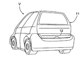
図1に示すように、自動車Vの後面を開閉するテールゲート11の下縁に沿って車体左右方向に延びる外装用ガーニッシュ12が装着される。
【0011】
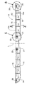
図2は外装用ガーニッシュ12の裏面(テールゲート11に対向する面)を示すものである。外装用ガーニッシュ12は中心線Lを挟んで左右対称な構造を有しているため、以下、図2における右半部(車体を基準にして左半部)の構造を説明する。外装用ガーニッシュ12は合成樹脂(例えば、ABS樹脂)を真空成形したガーニッシュ本体13を備えており、その長手方向に直交する横断面は溝状を成しており(図4参照)、その周囲には閉じた周縁開口部13aが形成される。
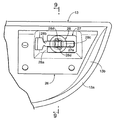
【0012】
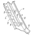
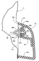
図3および図4を併せて参照すると明らかなように、ガーニッシュ本体13の内面には、その長手方向と直交する方向(上下方向)に延びる複数枚(実施例では4枚)の縦リブ14…が接着される。各縦リブ14はガーニッシュ本体13と同種の合成樹脂の板材を所定形状に切断したもので、ガーニッシュ本体13に接着した状態で該ガーニッシュ本体13の周縁開口部13aよりも距離α(図4参照)だけ内側に入り込んでいる。縦リブ14の中央よりも上寄りの位置と下端とに、それぞれ上部切欠14aおよび下部切欠14bが形成されており、上部切欠14aおよび下部切欠14bにそれぞれ横リブ15,16が係合して接着される。横リブ15,16はガーニッシュ本体13と同種の合成樹脂の板材を帯状に切断したもので、上側の横リブ15はガーニッシュ本体13に直接接触していないが、下側の横リブ16の下面は、ガーニッシュ本体13の底壁13bの内面に接着される。
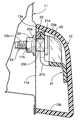
【0013】
図4に明瞭に示されるように、ガーニッシュ本体13の周縁開口部13aをテールゲート11のリヤパネル11aに密着させたとき、横リブ15,16の接合面15a,16aとリヤパネル11aの後面との間には若干の隙間β(例えば、0.5mm程度)が形成されており、この隙間βに介在する両面粘着テープ17,18で横リブ15,16の接合面15a,16aがリヤパネル11aに接合される。
【0014】
ガーニッシュ本体13は、前記両面粘着テープ17,18に加えて、その中心線L寄りの位置でリヤパネル11aにボルト止めされるとともに、その端部寄りの位置でリヤパネル11aにクリップ止めされる。
【0015】
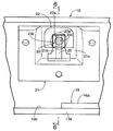
次に、図5〜図7を参照してボルト止め部分の構造を説明する。
【0016】
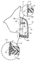
ガーニッシュ本体13と同種の合成樹脂で真空成形した第1ブラケット21が、ガーニッシュ本体13の内面に接着される。第1ブラケット21の中央部はガーニッシュ本体13の内面から離反するように膨らんだボルト支持部21aを備えており、このボルト支持部21aの一部に切欠21bが形成される。第1ブラケット21のボルト支持部21aの頂面に、コ字状に形成された所定厚さのスペーサ22が接着されており、そのスペーサ22の切欠22aはボルト支持部21aの切欠21bに重なっている。
【0017】
頭部23a、角軸部23bおよび雄ねじ部23cを備えたボルト23が、その頭部23aをボルト支持部21aの裏面に当接させ、その角軸部23bをボルト支持部21aの切欠21bおよびスペーサ22の切欠22aに回転不能に係合させ、かつ雄ねじ部23cがガーニッシュ本体13の周縁開口部13aから突出するように支持されており、このボルト23の雄ねじ部23cがリヤパネル11aのボルト孔11bを貫通してナット24に螺合することで、ガーニッシュ本体13がリヤパネル11aに固定される。このとき、ボルト23がガーニッシュ本体13の内部に脱落しないように、ボルト支持部21aの内面に接着したストッパ25がボルト23の頭部23aの背面に対向する。
【0018】
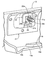
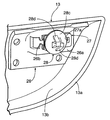
次に、図8〜図10を参照してクリップ止め部分の構造を説明する。
【0019】
ガーニッシュ本体13と同種の合成樹脂で真空成形した第2ブラケット26が、ガーニッシュ本体13の内面に接着される。第2ブラケット26の中央部はガーニッシュ本体13の内面から離反するように膨らんだクリップ支持部26aを備えており、このクリップ支持部26aの一部に切欠26bが形成される。第2ブラケット26のクリップ支持部26aの頂面に、コ字状に形成された所定厚さのスペーサ27が接着されており、そのスペーサ27の切欠27aはクリップ支持部26aの切欠26bに重なっている。
【0020】
頭部28a、軸部28b、受け部28cおよび一対の爪部28d,28dを備えたクリップ28が、その頭部28aをクリップ支持部26aの裏面に当接させ、その軸部28bをクリップ支持部26aの切欠26bおよびスペーサ27の切欠27aに係合させ、かつ爪部28d,28dがガーニッシュ本体13の周縁開口部13aから突出するように支持されており、このクリップ28の爪部28d,28dを弾性変形させながらリヤパネル11aの係止孔11cを貫通させて該リヤパネル11aの裏面に係止することで、ガーニッシュ本体13がリヤパネル11aに固定される。
【0021】
しかして、真空成形したガーニッシュ本体13に左右両半部に、それぞれ4枚の縦リブ14…、2枚の横リブ15,16、第1ブラケット21および第2ブラケット26を接着する。このとき、第1ブラケット21および第2ブラケット26には、適宜の厚さのスペーサ22,27が予め接着される。このようにして完成した外装用ガーニッシュ12の第1ブラケット21にボルト23を装着し、第2ブラケット26にクリップ28を装着し、更に2枚の横リブ15,16の接合面15a,16aに両面粘着テープ17,18を貼り付けた状態で、その外装用ガーニッシュ12をテールゲート11のリヤパネル11aの所定位置に固定する。
【0022】
即ち、左右2本のボルト23,23をリヤパネル11aの2個のボルト孔11b,11bに挿入してナット24,24で締結するとともに、左右2個のクリップ28,28をリヤパネル11aの2個の係止孔11c,11cに挿入して係止すると、前記両面粘着テープ17,18がリヤパネル11aに貼り付いて外装用ガーニッシュ12がテールゲート11に強固に固定される。このとき、第1ブラケット21に接着した所定厚さのスペーサ22によって、該スペーサ22がテールゲート11のリヤパネル11aに隙間なく密着し、ボルト23を締め付けたときのガーニッシュ本体13の歪みが防止される。また第2ブラケット26に接着した所定厚さのスペーサ27によって、クリップ28が軸方向に位置決めされて爪部28d,28dの確実な係止が可能になる。
【0023】
以上のように、外装用ガーニッシュ12のガーニッシュ本体13を真空成形したので、それを射出成形する場合に比べて金型の構造を簡素化し、大幅なコストダウンを可能にすることができる。真空成形を採用するとガーニッシュ本体13の内部に補強リブを一体成形することができないが、縦リブ14…および横リブ15,16を格子状の組み合わせたものをガーニッシュ本体13の内面に接着することで、ガーニッシュ本体13の内部をボックス構造にして充分な剛性を与えることができる。しかも縦リブ14…および横リブ15,16は合成樹脂の板材を所定の形状に切断しただけのものなので、極めて低コストである。
【0024】
またガーニッシュ本体13をテールゲート11のリヤパネル11aに両面粘着テープ17,18で接合する接合面15a,16aを、ガーニッシュ本体13の周縁開口部13aではなく、その内部に収納された横リブ15,16に設けたので、ガーニッシュ本体13の周縁開口部13aとリヤパネル11aとの隙間から両面粘着テープ17,18が見えなって外観が向上する。
【0025】
更に、真空成形品の特徴として、その周縁開口部13aに連なる底壁13bの肉厚が、他の部分(周縁開口部13aから離れた底部)に比べて大きく引き伸ばされるために薄くなってしまうが、下側の横リブ16を前記底壁13bに重ね合わせて接着したことにより、上述した肉厚の減少を補ってガーニッシュ本体13の剛性を確保することができる。
【0026】
更にまた、ガーニッシュ本体13、縦リブ14…、横リブ15,16、第1、第2ブラケット21,26等を全て同種の合成樹脂(例えば、ABS樹脂)で構成することにより、外装用ガーニッシュ12の効果的にリサイクルすることができる。
【0027】
以上、本発明の実施例を詳述したが、本発明はその要旨を逸脱しない範囲で種々の設計変更を行うことが可能である。
【0028】
例えば、実施例では外装用ガーニッシュ12の片側半部について4枚の縦リブ14…と2枚の横リブ15,16とを用いているが、それらの数は適宜変更可能である。
【0029】
また実施例では外装用ガーニッシュ12の片側半部について1個のボルト23と1個のクリップ28とを用いているが、ボルトおよびクリップの数は適宜変更可能であり、ボルトおよびクリップの一方だけを使用することもできる。
【0030】
また実施例では第1、第2ブラケット21,26を真空成形品で構成しているが、それらを射出成形品とすることもできる。
【0031】
また本発明の外装用ガーニッシュは、テールゲート11用に限定されるものではない。
【発明の効果】
以上のように請求項1に記載された発明によれば、合成樹脂を断面溝状に真空成形したガーニッシュ本体の内面に、その長手方向と交差する複数の縦リブを接着するとともに、これらの縦リブにガーニッシュ本体の長手方向に延びる複数の横リブを接着し、かつ前記横リブの少なくとも一つを、ガーニッシュ本体の周縁開口部に連なる壁部内面に接着したので、表皮だけで構成されて剛性に乏しく、かつ真空成形の過程で材料が引き伸ばされて前記壁部の肉厚が薄くなったガーニッシュ本体を格子状に組み合わされた縦リブおよび横リブで補強して充分な剛性を確保することができる。その結果、安価な真空成形品のガーニッシュ本体に射出成形品と同等の剛性を与えてコストダウンに寄与することができる。しかも横リブに設けた接合面を両面粘着テープを介して車体の外表面に接合する際に、前記壁部内面に接着される横リブの接合面とガーニッシュ本体の周縁開口部との間に両面粘着テープを収納する隙間を形成したので、ガーニッシュ本体の周縁開口部と車体の外表面との隙間から両面粘着テープが見えることがなくなり、外観の向上に寄与することができる。
【図面の簡単な説明】
【図1】 外装用ガーニッシュを装着した自動車の斜視図
【図2】 外装用ガーニッシュの裏面を示す図
【図3】 外装用ガーニッシュの部分斜視図
【図4】 図2の4−4線拡大断面図
【図5】 図2の5部拡大図
【図6】 図5の6−6線断面図
【図7】 ボルト止め部分の斜視図
【図8】 図2の8部拡大図
【図9】 図8の9−9線断面図
【図10】 クリップ止め部分の斜視図
【符号の説明】
11 テールゲート(車体)
11a リヤパネル(外表面)
13 ガーニッシュ本体
13a 周縁開口部
13b 底壁(壁部)
14 縦リブ
15 横リブ
15a 接合面
16 横リブ
16a 接合面
17 両面粘着テープ
18 両面粘着テープ
β 隙間 [0001]
BACKGROUND OF THE INVENTION
The present invention relates to an automotive exterior garnish that includes a garnish body that is formed by vacuum forming a synthetic resin so that a cross section perpendicular to the longitudinal direction forms a groove shape, and that is attached so that a peripheral opening thereof is in contact with an outer surface of a vehicle body.
[0002]
[Prior art]
An exterior garnish for enhancing decoration is attached to the body of an automobile, and the following patent document discloses a decorative panel made of synthetic resin attached to a tailgate of an automobile. In general, this type of exterior garnish is attached to the vehicle body via clips and bolts, and on the inner surface thereof, reinforcing ribs for increasing rigidity are formed in addition to the support portions of the clips and bolts. Manufactured by injection molding capable of forming a shaped member.
[0003]
[Patent Literature]
Japanese Patent No. 311668 [0004]
[Problems to be solved by the invention]
By the way, vacuum forming exterior garnishes can greatly reduce costs due to the simple structure of the mold, but the vacuum molded product is composed of only a thin skin and lacks rigidity. There is a problem, and further, there is a problem that hinders the mounting because the support portions of the clip and the bolt cannot be formed integrally. Also, when fixing the exterior garnish to the vehicle body, double-sided adhesive tape is used in addition to clips and bolts, but in the case of vacuum molded products without reinforcing ribs, the peripheral opening is attached to the vehicle body with double-sided adhesive tape. There is a possibility that the double-sided pressure-sensitive adhesive tape can be seen from the gap between the exterior garnish and the vehicle body and the appearance may be deteriorated.
[0005]
The present invention has been made in view of the above-mentioned circumstances, and can be adopted as an inexpensive vacuum-formed product for an automobile exterior garnish, and the appearance is improved by making the double-sided adhesive tape for mounting invisible from the outside. The purpose is to let you.
[0006]
[Means for Solving the Problems]
In order to achieve the above object, according to the first aspect of the present invention, a garnish body is formed by vacuum forming a synthetic resin so that a cross-section perpendicular to the longitudinal direction forms a groove shape, and the peripheral opening of the garnish body A garnish for automobile exterior mounted so as to be in contact with the outer surface of the garnish, wherein a plurality of vertical ribs intersecting the longitudinal direction are bonded to the inner surface of the garnish body, and a plurality of lateral ribs extending in the longitudinal direction of the garnish body Is bonded to the vertical rib , and at least one of the horizontal ribs is bonded to the inner surface of the wall portion continuous with the peripheral opening of the garnish body, and the surface of the horizontal rib on the peripheral opening side is made of a double-sided adhesive tape. It forms a clearance for accommodating the double-sided adhesive tape between the bonding surface of the outer surface and the bonding surface of the transverse rib is adhered to the wall inner surface and said peripheral opening of Exterior garnish of a motor vehicle is proposed, characterized in that the.
[0007]
Multiple According to the above configuration, the inner surface of the garnish main body was vacuum molding synthetic resin to cross groove, while bonding a plurality of longitudinal ribs that intersect with the longitudinal direction, extending in the longitudinal direction of the garnish main body to those of the longitudinal ribs process of horizontal ribs bonded, and at least one of the transverse ribs, so adhered to the wall inner surface contiguous to the peripheral opening of the garnish main body, consists only of the skin rather poor in stiffness, and vacuum forming Thus, the garnish body, whose material has been stretched and the wall portion has become thin, can be reinforced with vertical and horizontal ribs combined in a lattice shape to ensure sufficient rigidity. As a result, the garnish main body of an inexpensive vacuum molded product can be given rigidity equivalent to that of an injection molded product, thereby contributing to cost reduction. Moreover, when the joining surface provided on the lateral rib is joined to the outer surface of the vehicle body via the double-sided adhesive tape, both sides are provided between the joining surface of the lateral rib adhered to the inner surface of the wall and the peripheral opening of the garnish body. Since the gap for accommodating the adhesive tape is formed, the double-sided adhesive tape is not seen from the gap between the peripheral opening of the garnish body and the outer surface of the vehicle body, which can contribute to the improvement of the appearance.
[0008]
The
[0009]
DETAILED DESCRIPTION OF THE INVENTION
Hereinafter, embodiments of the present invention will be described based on examples of the present invention shown in the accompanying drawings. 1 to 10 show an embodiment of the present invention, FIG. 1 is a perspective view of an automobile equipped with an exterior garnish, FIG. 2 is a view showing the back surface of the exterior garnish, and FIG. 4 is an enlarged sectional view taken along line 4-4 of FIG. 2, FIG. 5 is an enlarged view of
[0010]
As shown in FIG. 1, an
[0011]
FIG. 2 shows the back surface of the exterior garnish 12 (the surface facing the tailgate 11). Since the
[0012]
3 and 4 together, the inner surface of the
[0013]
As clearly shown in FIG. 4, when the
[0014]
The
[0015]
Next, the structure of the bolting portion will be described with reference to FIGS.
[0016]
A
[0017]
A
[0018]
Next, the structure of the clip retaining portion will be described with reference to FIGS.
[0019]
A
[0020]
A
[0021]
Then, the four
[0022]
That is, the two left and
[0023]
As described above, since the garnish
[0024]
Also, the joining
[0025]
Further, as a feature of the vacuum molded product, the thickness of the
[0026]
Further, the
[0027]
As mentioned above, although the Example of this invention was explained in full detail, this invention can perform a various design change in the range which does not deviate from the summary.
[0028]
For example, in the embodiment, four
[0029]
In the embodiment, one
[0030]
Moreover, although the 1st,
[0031]
Further, the exterior garnish of the present invention is not limited to the
【The invention's effect】
As described above, according to the first aspect of the present invention, a plurality of vertical ribs intersecting the longitudinal direction are bonded to the inner surface of a garnish body vacuum-formed with a synthetic resin in a cross-sectional groove shape. A plurality of lateral ribs extending in the longitudinal direction of the garnish main body are bonded to the ribs, and at least one of the lateral ribs is bonded to the inner surface of the wall portion connected to the peripheral opening of the garnish main body. rigidity rather poor, and to ensure sufficient stiffness garnish body wall thickness of the wall material is stretched to become thin in the course reinforced with longitudinal ribs and transverse ribs are combined in a grid of vacuum forming be able to. As a result, the garnish main body of an inexpensive vacuum molded product can be given rigidity equivalent to that of an injection molded product, thereby contributing to cost reduction. Moreover, when the joining surface provided on the lateral rib is joined to the outer surface of the vehicle body via the double-sided adhesive tape, both sides are provided between the joining surface of the lateral rib adhered to the inner surface of the wall and the peripheral opening of the garnish body. Since the gap for accommodating the adhesive tape is formed, the double-sided adhesive tape is not seen from the gap between the peripheral opening of the garnish body and the outer surface of the vehicle body, which can contribute to the improvement of the appearance.
[Brief description of the drawings]
FIG. 1 is a perspective view of an automobile equipped with an exterior garnish. FIG. 2 is a view showing a rear surface of the exterior garnish. FIG. 3 is a partial perspective view of the exterior garnish. 5 is an enlarged view of
11 Tailgate (body)
11a rear panel (outer surface)
13
14
β gap
Claims (1)
ガーニッシュ本体(13)の内面に、その長手方向と交差する複数の縦リブ(14)を接着するとともに、ガーニッシュ本体(13)の長手方向に延びる複数の横リブ(15,16)を前記縦リブ(14)に接着し、かつ前記横リブ(15,16)の少なくとも一つを、ガーニッシュ本体(13)の周縁開口部(13a)に連なる壁部(13b)内面に接着し、
前記横リブ(15,16)の前記周縁開口部(13a)側の面を両面粘着テープ(17,18)による車体(11)の外表面(11a)への接合面(15a,16a)とし、かつ前記壁部(13b)内面に接着される前記横リブ(16)の前記接合面(16a)と前記周縁開口部(13a)との間に前記両面粘着テープ(18)を収納する隙間(β)を形成したことを特徴とする自動車の外装用ガーニッシュ。A garnish main body (13) is formed by vacuum-forming synthetic resin so that a cross section perpendicular to the longitudinal direction forms a groove shape, and the peripheral opening (13a) is attached so as to be in contact with the outer surface (11a) of the vehicle body (11). Car exterior garnish,
A plurality of vertical ribs (14) intersecting the longitudinal direction of the garnish body (13) are bonded to the inner surface of the garnish body (13), and a plurality of horizontal ribs (15, 16) extending in the longitudinal direction of the garnish body (13) are attached to the longitudinal ribs. (14) and at least one of the lateral ribs (15, 16) is bonded to the inner surface of the wall (13b) connected to the peripheral opening (13a) of the garnish body (13),
The side surface of the lateral rib (15, 16) on the peripheral opening (13a) side is a joint surface (15a, 16a) to the outer surface (11a) of the vehicle body (11) by the double-sided adhesive tape (17, 18) , And a gap (β for housing the double-sided adhesive tape (18) between the joint surface (16a) of the lateral rib (16) and the peripheral opening (13a) bonded to the inner surface of the wall (13b). ), A garnish for an exterior of an automobile.
Priority Applications (1)
| Application Number | Priority Date | Filing Date | Title |
|---|---|---|---|
| JP2002317134A JP3819829B2 (en) | 2002-10-31 | 2002-10-31 | Garnish for car exterior |
Applications Claiming Priority (1)
| Application Number | Priority Date | Filing Date | Title |
|---|---|---|---|
| JP2002317134A JP3819829B2 (en) | 2002-10-31 | 2002-10-31 | Garnish for car exterior |
Publications (2)
| Publication Number | Publication Date |
|---|---|
| JP2004149005A JP2004149005A (en) | 2004-05-27 |
| JP3819829B2 true JP3819829B2 (en) | 2006-09-13 |
Family
ID=32460597
Family Applications (1)
| Application Number | Title | Priority Date | Filing Date |
|---|---|---|---|
| JP2002317134A Expired - Lifetime JP3819829B2 (en) | 2002-10-31 | 2002-10-31 | Garnish for car exterior |
Country Status (1)
| Country | Link |
|---|---|
| JP (1) | JP3819829B2 (en) |
Families Citing this family (1)
| Publication number | Priority date | Publication date | Assignee | Title |
|---|---|---|---|---|
| JP6055747B2 (en) * | 2013-09-20 | 2016-12-27 | 株式会社豊田自動織機 | Backdoor garnish |
-
2002
- 2002-10-31 JP JP2002317134A patent/JP3819829B2/en not_active Expired - Lifetime
Also Published As
| Publication number | Publication date |
|---|---|
| JP2004149005A (en) | 2004-05-27 |
Similar Documents
| Publication | Publication Date | Title |
|---|---|---|
| US7537253B2 (en) | Method for attaching a polished metal grille surround | |
| JP3052766B2 (en) | Impact energy absorption structure by car interior materials | |
| JP4903044B2 (en) | Plastic panel attached to automobile | |
| JP7583545B2 (en) | Vehicle side outer structure | |
| JP2001130340A (en) | Complex component for automobile | |
| JP3819829B2 (en) | Garnish for car exterior | |
| JP2972130B2 (en) | Mounting structure of pull handle for door trim | |
| JP3610800B2 (en) | Sound insulation mounting structure in front fender | |
| JP2584305Y2 (en) | Automotive door lining | |
| JP3875625B2 (en) | Side sill garnish mounting structure | |
| JPH0133402Y2 (en) | ||
| JP3092475B2 (en) | Vehicle roof header tray | |
| JP3701418B2 (en) | Instrument panel structure for vehicles | |
| JP3144669B2 (en) | Pocket structure in automotive interior parts | |
| US20050189775A1 (en) | Vehicle trim panel with integrated seal | |
| JP3275693B2 (en) | Automotive bumper mounting structure | |
| JPH0221349Y2 (en) | ||
| JP3604027B2 (en) | Mudguards for cars | |
| JP2511208Y2 (en) | Rear parcel trim for automobile | |
| JP4231566B2 (en) | Car trim | |
| JPH0514948Y2 (en) | ||
| JPH11129933A (en) | Roof bow for automobile | |
| JP2006035997A (en) | Molded ceiling for automobile | |
| JPH054415Y2 (en) | ||
| CN119664905A (en) | Vehicle sealing components |
Legal Events
| Date | Code | Title | Description |
|---|---|---|---|
| A977 | Report on retrieval |
Free format text: JAPANESE INTERMEDIATE CODE: A971007 Effective date: 20060210 |
|
| A131 | Notification of reasons for refusal |
Free format text: JAPANESE INTERMEDIATE CODE: A131 Effective date: 20060315 |
|
| A521 | Written amendment |
Free format text: JAPANESE INTERMEDIATE CODE: A523 Effective date: 20060508 |
|
| TRDD | Decision of grant or rejection written | ||
| A01 | Written decision to grant a patent or to grant a registration (utility model) |
Free format text: JAPANESE INTERMEDIATE CODE: A01 Effective date: 20060531 |
|
| A61 | First payment of annual fees (during grant procedure) |
Free format text: JAPANESE INTERMEDIATE CODE: A61 Effective date: 20060615 |
|
| R150 | Certificate of patent or registration of utility model |
Free format text: JAPANESE INTERMEDIATE CODE: R150 |
|
| FPAY | Renewal fee payment (event date is renewal date of database) |
Free format text: PAYMENT UNTIL: 20090623 Year of fee payment: 3 |
|
| FPAY | Renewal fee payment (event date is renewal date of database) |
Free format text: PAYMENT UNTIL: 20100623 Year of fee payment: 4 |