JP3817618B2 - Billet feeder - Google Patents
Billet feeder Download PDFInfo
- Publication number
- JP3817618B2 JP3817618B2 JP27873199A JP27873199A JP3817618B2 JP 3817618 B2 JP3817618 B2 JP 3817618B2 JP 27873199 A JP27873199 A JP 27873199A JP 27873199 A JP27873199 A JP 27873199A JP 3817618 B2 JP3817618 B2 JP 3817618B2
- Authority
- JP
- Japan
- Prior art keywords
- billet
- holder
- shutter
- supply device
- carry
- Prior art date
- Legal status (The legal status is an assumption and is not a legal conclusion. Google has not performed a legal analysis and makes no representation as to the accuracy of the status listed.)
- Expired - Fee Related
Links
- 238000005242 forging Methods 0.000 claims description 13
- 230000002159 abnormal effect Effects 0.000 claims description 2
- 230000005856 abnormality Effects 0.000 description 10
- 238000010586 diagram Methods 0.000 description 4
- 238000010438 heat treatment Methods 0.000 description 2
- 230000005540 biological transmission Effects 0.000 description 1
- 230000002079 cooperative effect Effects 0.000 description 1
- 238000007599 discharging Methods 0.000 description 1
- 230000000694 effects Effects 0.000 description 1
- 238000012423 maintenance Methods 0.000 description 1
- 238000000034 method Methods 0.000 description 1
Images
Landscapes
- Forging (AREA)
Description
【0001】
【発明の属する技術分野】
本発明は、鍛造プレスに被加工素材であるビレットを送りこむためのビレット供給装置に関する。
【0002】
【従来の技術】
鍛造プレスで加工する素材(ビレット)を金型に随時送りこみ、自動的に加工する装置として、ビレットを所定の位置で受け入れて金型まで運ぶトランスフア装置を設置した自動鍛造プレスがある。この種の自動鍛造プレスで連続的に加工を行うためには、加熱炉で加熱され搬送コンベアで搬送されて来たビレットをトランスファ装置への引き渡し位置まで自動的に移送する装置が必要となる。
【0003】
このようなビレット供給装置としては種々のものが提案されている。例えば実公平7−7003号公報には、トランスファ装置の動作に連動してビレットを分離、供給する装置が記載されている。この装置は、トランスファ装置の動作と連動するのでタイミングにズレを生じないという利点がある。
【0004】
また、特開平11−156478号公報には、長尺な素材( ビレット) を分離、供給する装置であって、搬入シュート4から滑落して来たビレットを筒状のホルダ1fに挿入し、シリンダによってホルダを回動させてビレットをトランスファ装置がチャッキングする位置に供給する装置が記載されている。
【0005】
【発明が解決しようとする課題】
上記実公平7−7003号公報記載のビレット供給装置は、トランスファ装置の動作に連動させるための機構が必要で、これによって装置が複雑となり、かつ伝動機構部にトラブルが発生すると装置全体が停止するという問題点がある。一方、特開平11−156478号公報記載のビレット供給装置は、トランスファ装置と連動するのでなく、単独の供給装置であるから、運転調整( ビレットを受ける位置、供給する位置等の調整) が簡単であり、前記実公平7−7003号公報記載の装置のような複雑さがなく、供給装置単独でメンテナンスができるので実公平7−7003号公報の装置の上記問題点は解消されている。
【0006】
しかしながら、上記両従来技術に共通する問題点として、搬入シュートから滑落して来たビレットをホルダに受け入れて供給位置に供給する時、自動鍛造プレスラインのどこかでトラブルが発生した場合は、ビレットを自動鍛造プレスに供給せず、他の場所へ逃がす必要があるが、その対策がされていないのでトラブルが生じるという問題点がある。さらに、ビレットの径が変わった場合ホルダの交換が必要であるという問題点もある。本発明は、これら従来装置の問題点を解決することを課題としている。
【0007】
【課題を解決するための手段】
上記課題を解決するために本発明は、次のような構成とした。すなわち、本発明のビレット供給装置は、搬送コンベアの終端部に設けられた搬入シュ―トから滑落してくるビレットを受け取って鍛造プレスに送りこむビレット供給装置において、前記搬入シュ―トから滑落してくるビレットを受け入れるホルダの底部に、該ビレットが下方へ落下しないように受け止める開閉自在なシャッタを設けるとともに、前記ホルダをビレット受入位置から所定の引き渡し位置まで移動させるホルダ移動装置と、前記シャッタを正常時は閉じた状態に保ち、異常時には開いてビレットを下方に排出するように駆動するシャッタ駆動装置とを設けて、前記受入位置と引き渡し位置のいずれにおいてもホルダのビレットを下方へ排出可能としたことを特徴としている。
【0008】
このビレット供給装置は、搬送コンべアの終端部に設けられた搬入シュートと自動鍛造プレスの受入位置との間に設置される。上記搬送コンベアで送られてきたビレットが搬入シュートから滑落してビレット供給装置のホルダに受け入れられる。この時ホルダの底板として機能するシャッタが閉じていて、ビレットが当該シャッタによって受け止められる。このビレットをチャックが挟持したのち、ホルダが自動鍛造プレスの受入位置まで移動し、ここで当該自動鍛造プレスに設けられているトランスファ装置にビレットを引き渡す。
【0009】
上記ホルダのシャッタは正常時は閉じているので、搬入シュートから滑落してきたビレットが該シャッタ上に受け止められ、トランスファ装置への引き渡し位置に運ばれて該トランスファ装置に引き渡されるが、自動鍛造プレスに何らかの異常が生じた時は、該シャッタが開いて、搬入シュートから滑落してきたビレットをそのまま下方へ排出する。また、ビレットがホルダに受け止められ、トランスファへ装置への引き渡し位置まできた時に自動鍛造プレスに異常が発生した時は、今まで閉じていたチャックが開いて、ビレットを解放する。ホルダの下側にはシャッタが位置しないので、チャックから外れたビレットは下方へ排出される。このため、トランスファ装置には引き渡されない。
【0010】
ビレット供給装置のビレットを保持する部分をエアシリンダで開閉するチャックとしておけば、エアには被圧縮性があるので、ビレットの径が変わっても確実にチャックできることとなり、従来技術のごとくホルダを交換する必要がなくなる。
【0011】
【発明の実施の形態】
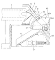
本発明の実施の形態を図に基づいて説明する。図1以下の各図はビレット供給装置を表すもので、このビレット供給装置1は、加熱炉で加熱されたビレットを搬送してくる搬送コンべアCの終端部に設けられている搬入シュートSと自動鍛造プレスのトランスファ装置(図示を省略)との間に設置されている。ビレット供給装置(以下「供給装置」と略称する)1の基台2は搬送コンベアCの架台3に取り付けられていて、この基台2に搬入シュートSが取り付けられている。
【0012】
搬入シュートSは、その基部をなすフランジ9が前記基台2の上面に固着したブラケット7のフランジ8に固着されている。この搬入シュートSの樋10の上端部は前記搬送コンベアの終端部に臨み、当該樋10の下端部に接続された傾斜の大きい誘導樋11の下端部が供給装置1に臨んでいる。これら樋10と誘導樋11の上方には、ビレットの飛び出しを防止する下向き樋状のカバー12,13が設けられている。
【0013】
供給装置1の前記基台2上部に固設したブラケット20に軸受け部材21が設けられ、該軸受け部材でシャフト25が支承されている。このシャフト25には、一対のレバー27,27が、その共通のボス部27aに内装しているテーパ型固定金具28a,28bによって固定され、該シャフト25の端部25aに回動レバー30が固着されている。この回動レバー30の先端部には、二股金具33が遊嵌されピン31で止められている。一方、上記基台2に端部支持型のエアシリンダ35が取り付けられ、このエアシリンダのピストンロッド先端部に前記二股金具33が連結されている。したがって、前記レバー27は、エアシリンダ35の伸縮によりシャフト25を中心として図1、2の如く左右に回動する。
【0014】
レバー27の外縁部には円弧状の受け部39a,39bが設けられ、これら受け部の間隔部にホルダ40が設けられている。ホルダ40は、ビレットが嵌り込む空間部を備え、この部分に開閉式のチャック41,41が設けられている。チャック41は、互いに対向する面がV溝状に形成され、その背面部にはロッド42が連結されている。このロッド42はエアシリンダ43に挿通されていて、その後端部にはピストン45が取り付けられている。エアシリンダ43の後端部には、前記ピストンの後側へエアを供給するエア供給口46が設けられ、外部のエア源と接続されている。また、エアシリンダ43の内部には、チャック41を後退させる方向(開方向)に付勢するスプリング48が設けられている。
【0015】
前記レバー27,27の間隔部にはシャッタ用のレバー50が設けられている。このレバー50の中間部50aは前記シャフト25に回動自在に遊嵌されていて、その下端部50bはエアシリンダ53の先端部の二股金具53aにピン53bで連結されている。したがって、エアシリンダ53を伸縮させるとシャッタ55を取り付けたレバー50が左右に回動する。
【0016】
レバー50の上部は、左右一対の側板50c,50cに分岐した二股状に形成され、その上縁部に、一対の側板50c,50cの間隔部を部分的に覆蓋するように側面視円弧状の板体からなるシャッタ55が取り付けられている(図4、5参照)。このシャッタ55の下側は空洞部57となっていて、レバー50の分岐部の基部には、前記空洞部57の下方に位置する傾斜案内面50dが形成されている。また、この傾斜案内面50dの先端部には、該傾斜案内面上を滑落してくるビレットを受け取って所定の位置まで滑落させる傾斜樋状のバイパスシュート54が設けられている。上記傾斜案内面50dとバイパスシュート54は、落下したビレットを所定の排出場所に案内するバイパスラインを形成する。
【0017】
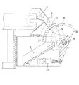
次に、このビレット供給装置1の動作について説明する。搬入シュートSからのビレットBの滑落を待機している初期状態では、エアシリンダ35が収縮していて、図5に示すように、レバー27が同図の左側に回動しホルダ40が搬入シュートSの出口に臨むビレット受入位置Xに位置している。また、シャッタ用のエアシリンダ53は伸長してレバー50がその回動範囲の左端位置に位置し、シャッタ55がホルダ40の底部を遮蔽している。
【0018】
この状態で、搬送コンベアCによって搬送されてきたビレットBは、搬入シュートSの樋10から誘導樋11を自重で滑動し、供給装置1のホルダ40内に落下供給される。このとき、ホルダ40の底部はシャッタ55で覆われているのでビレットが下方へ落下することはない。ホルダ40内にビレットが嵌り込むと、チャック装置のエアシリンダ43にエアが供給され、チャック41,41が前進してビレットを挟持する。
【0019】
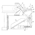
次に、図2、6に示すように、エアシリンダ35が伸長し、レバー27が図の右向きに回動して、ホルダ40が引き渡し位置(トランスファ装置の受入位置)Yに移動する。この位置で、トランスファ装置のチャックがホルダのビレットをつかみ、ホルダのチャック41,41が開いて該ビレットが自動プレスのトランスファ装置に引き渡される。引き渡されたビレットは自動プレスの金型に供給され加工される。上記引き渡しが終了すると、チャック41,41が開いたままレバー27が図6の左向きに回動し、ホルダ40が図5に示す通り元のビレット受入位置Xまで復帰する。
【0020】
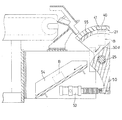
上記ビレットの受け入れ時において、自動プレスに何らかの異常が生じた時は、エアシリンダ53が収縮してレバー50が図7に示すように右向きに回動し、シャッタ55をホルダ40の直下部から右側へ移動させる。このため、ホルダ40の底板がなくなり、搬入シュートから落下してきたビレットBがそのまま下方へ落下して傾斜案内面50d、バイパスシュート54を通って外部へ排出される。この結果、停止している自動プレスにビレットが無理やり供給される事故が避けられるのである。
【0021】
また、ビレット受入時には正常であったが、引き渡し位置Yにビレットを運んだ時に自動プレスに異常が発生した時は、図8に示すように、トランスファ装置がビレットを受け取る前にホルダのチャック41,41が開く。この時、エアシリンダ53は伸長しており、シャッタ55は受入位置Xに残留したままで、ホルダの底板が解放された状態となっているため、ホルダ内のビレットは下方へ落下し、外部へ排出される。
【0022】
このように、後続の工程に異常が発生し、後続装置が停止した時は、該装置に供給されるべきビレットをバイパスラインを通して外部に排出するので、停止した装置にビレットが次々と供給されることによるトラブルが避けられるのである。なお、上記エアシリンダ35、53、チャック41等の動作は自動制御されていて、後続の装置である自動プレスの停止に連動してビレット排出操作を行うようになっているが、異常発生時におけるビレットの排出を手動によるスイッチ操作で行うようにしてもよいことは言うまでもない。
【0023】
【発明の効果】
以上の説明から明らかなように、本発明に係るビレット供給装置は、常時は自動的にビレットを受け取って後続の装置に供給することができると共に、後続の装置に何らかの異常が発生した時は、シャッタとチャックとの協働作用によって受け入れたビレットを後続装置に供給せず、別のラインを通して外部に排出することができるので、後続装置の異常にうまく対応し、余計なトラブルを避けることが可能となった。なお、異常の説明では被加工材であるビレットを自動プレスに供給する装置として説明したが、このビレット供給装置を他の物品の移送装置や供給装置として使用できることは言うまでもない。
【図面の簡単な説明】
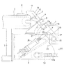
【図1】ビレット供給装置の正面図である。
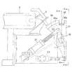
【図2】ホルダが引き渡し位置に移動した状態におけるその正面図である。
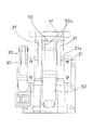
【図3】図2におけるF−F矢視図である。
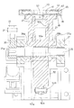
【図4】図2におけるG−G矢視で表わした側部断面図である。
【図5】受入状態における動作の説明図である。
【図6】引き渡し状態における動作の説明図である。
【図7】異常発生時における動作の説明図である。
【図8】異常発生時における動作の説明図である。
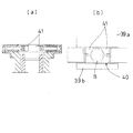
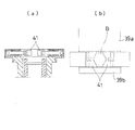
【図9】チャックの開状態における断面図(a)及び平面図(b)である。
【図10】チャックの閉状態における断面図(a)及び平面図(b)である。
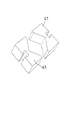
【図11】チャックの斜視図である。
【符号の説明】
1 ビレット供給装置
2 基台
20 ブラケット
25 シャフト
27 レバー
30 回動レバー
35 エアシリンダ(ホルダ移動装置)
40 ホルダ
50 レバー
53 エアシリンダ(シャッタ駆動装置)
55 シャッタ
B ビレット
S 搬入シュート
C コンベア[0001]
BACKGROUND OF THE INVENTION
The present invention relates to a billet supply device for feeding a billet, which is a material to be processed, to a forging press.
[0002]
[Prior art]
There is an automatic forging press equipped with a transfer device that receives a billet at a predetermined position and carries it to a die as a device that automatically feeds a material (billet) to be processed by a forging press into a die at any time. In order to perform continuous processing with this type of automatic forging press, a device for automatically transferring the billet heated in the heating furnace and transported by the transport conveyor to the transfer position to the transfer device is required.
[0003]
Various types of billet supply devices have been proposed. For example, Japanese Utility Model Publication No. 7-7003 describes a device for separating and supplying billets in conjunction with the operation of the transfer device. This device is advantageous in that it does not cause a timing shift because it is linked with the operation of the transfer device.
[0004]
Japanese Patent Application Laid-Open No. 11-156478 discloses a device for separating and supplying a long material (billet), in which a billet that has been slid down from a carry-in chute 4 is inserted into a cylindrical holder 1f. It is described in thus device for supplying billets is rotated to a position where the transfer device is chucking the holder.
[0005]
[Problems to be solved by the invention]
The billet supply device described in Japanese Utility Model Publication No. 7-7003 requires a mechanism for interlocking with the operation of the transfer device, which complicates the device and stops the entire device when trouble occurs in the transmission mechanism. There is a problem. On the other hand, the billet supply device described in Japanese Patent Application Laid-Open No. 11-156478 is not linked to the transfer device, but is a single supply device, so operation adjustment (adjustment of the billet receiving position, supply position, etc.) is simple. There is no complexity as in the apparatus described in the Japanese Utility Model Publication No. 7-7003, and maintenance can be performed by the supply device alone.
[0006]
However, as a problem common to both of the above prior arts, when a billet sliding down from the carry-in chute is received in the holder and supplied to the supply position, if a trouble occurs somewhere in the automatic forging press line, the billet Is not supplied to the automatic forging press, but it is necessary to let it go to another place. Furthermore, there is a problem that the holder needs to be replaced when the diameter of the billet changes. An object of the present invention is to solve the problems of these conventional devices.
[0007]
[Means for Solving the Problems]
In order to solve the above problems, the present invention has the following configuration. That is, the billet supply device of the present invention is a billet supply device that receives a billet sliding down from a carry-in shunt provided at the terminal end of a conveyor and sends it to a forging press. the bottom of the holder to receive the coming billet, together with the billet provided openable shutter to catch against falling downward, and the holder moving device for moving the front Symbol holder from billet receiving position to a predetermined delivery position, the shutter Provided with a shutter drive device that keeps closed during normal operation and opens to discharge the billet downward when abnormal, so that the billet of the holder can be discharged downward at both the receiving position and the delivery position. It is characterized by that.
[0008]
This billet supply device is installed between the carry-in chute provided at the terminal end of the conveyor and the receiving position of the automatic forging press. The billet sent by the conveyor is slid down from the carry-in chute and is received by the holder of the billet supply device. At this time, the shutter functioning as the bottom plate of the holder is closed, and the billet is received by the shutter. After the billet is clamped by the chuck, the holder moves to the receiving position of the automatic forging press, and the billet is handed over to a transfer device provided in the automatic forging press.
[0009]
Since the shutter of the holder is normally closed, the billet sliding down from the carry-in chute is received on the shutter and is transferred to the transfer device and transferred to the transfer device. When any abnormality occurs, the shutter is opened, and the billet sliding down from the carry-in chute is discharged as it is. Further, when the billet is received by the holder and an abnormality occurs in the automatic forging press when it reaches the transfer position to the transfer device, the chuck that has been closed is opened and the billet is released. Since the shutter is not positioned below the holder, the billet detached from the chuck is discharged downward. For this reason, it is not delivered to the transfer device.
[0010]
Once you have a chuck to open and close the portion holding the billet billet supply device in an air sheet cylinder, because the air has to be compressible, will be able to chuck reliably be changed diameter of the billet, the prior art as the holder No need to replace.
[0011]
DETAILED DESCRIPTION OF THE INVENTION
Embodiments of the present invention will be described with reference to the drawings. Each figure after FIG. 1 represents a billet supply device, and this billet supply device 1 is a carry-in chute S provided at a terminal end of a conveyance conveyor C that conveys a billet heated in a heating furnace. And an automatic forging press transfer device (not shown). A
[0012]
The carry-in chute S is fixed to the flange 8 of the bracket 7 in which the flange 9 forming the base is fixed to the upper surface of the
[0013]
A
[0014]
Arc-shaped receiving
[0015]
A
[0016]
The upper portion of the
[0017]
Next, operation | movement of this billet supply apparatus 1 is demonstrated. In the initial state waiting for the billet B to slide off from the carry-in chute S, the
[0018]
In this state, the billet B transported by the transport conveyor C slides on the
[0019]
Next, as shown in FIGS. 2 and 6, the
[0020]
When any abnormality occurs in the automatic press when the billet is received, the
[0021]
Also, when the billet is received normally, but when an abnormality occurs in the automatic press when the billet is carried to the delivery position Y, as shown in FIG. 8, before the transfer device receives the billet, the
[0022]
As described above, when an abnormality occurs in the subsequent process and the subsequent apparatus stops, the billet to be supplied to the apparatus is discharged to the outside through the bypass line, so that the billets are successively supplied to the stopped apparatus. Troubles caused by things can be avoided. The operations of the
[0023]
【The invention's effect】
As is clear from the above description, the billet supply device according to the present invention can always automatically receive the billet and supply it to the subsequent device, and when any abnormality occurs in the subsequent device, The billet received by the cooperative action of the shutter and the chuck can be discharged to the outside through another line without supplying it to the subsequent device, so it is possible to cope with abnormalities in the subsequent device and avoid unnecessary troubles. It became. In the description of the abnormality, the billet, which is a workpiece, is described as an apparatus that supplies the automatic press, but it goes without saying that the billet supply apparatus can be used as a transfer apparatus or supply apparatus for other articles.
[Brief description of the drawings]
FIG. 1 is a front view of a billet supply device.
FIG. 2 is a front view of the holder when it is moved to a delivery position.
FIG. 3 is a view taken along line FF in FIG. 2;
4 is a side cross-sectional view taken along line GG in FIG. 2. FIG.
FIG. 5 is an explanatory diagram of an operation in an acceptance state.
FIG. 6 is an explanatory diagram of an operation in a delivery state.
FIG. 7 is an explanatory diagram of an operation when an abnormality occurs.
FIG. 8 is an explanatory diagram of an operation when an abnormality occurs.
9A and 9B are a cross-sectional view (a) and a plan view (b) when the chuck is open.
10A and 10B are a cross-sectional view (a) and a plan view (b) when the chuck is closed.
FIG. 11 is a perspective view of a chuck.
[Explanation of symbols]
1
40
55 Shutter B Billet S Carrying chute C Conveyor
Claims (3)
Priority Applications (1)
| Application Number | Priority Date | Filing Date | Title |
|---|---|---|---|
| JP27873199A JP3817618B2 (en) | 1999-09-30 | 1999-09-30 | Billet feeder |
Applications Claiming Priority (1)
| Application Number | Priority Date | Filing Date | Title |
|---|---|---|---|
| JP27873199A JP3817618B2 (en) | 1999-09-30 | 1999-09-30 | Billet feeder |
Publications (2)
| Publication Number | Publication Date |
|---|---|
| JP2001105094A JP2001105094A (en) | 2001-04-17 |
| JP3817618B2 true JP3817618B2 (en) | 2006-09-06 |
Family
ID=17601428
Family Applications (1)
| Application Number | Title | Priority Date | Filing Date |
|---|---|---|---|
| JP27873199A Expired - Fee Related JP3817618B2 (en) | 1999-09-30 | 1999-09-30 | Billet feeder |
Country Status (1)
| Country | Link |
|---|---|
| JP (1) | JP3817618B2 (en) |
Cited By (1)
| Publication number | Priority date | Publication date | Assignee | Title |
|---|---|---|---|---|
| CN107757090A (en) * | 2016-08-16 | 2018-03-06 | 博罗承创精密工业有限公司 | One kind brushes black machine automatically |
Families Citing this family (3)
| Publication number | Priority date | Publication date | Assignee | Title |
|---|---|---|---|---|
| CN104128555A (en) * | 2014-07-24 | 2014-11-05 | 江苏利普机械有限公司 | Automatic material pouring device of hot die forging production line |
| KR102031890B1 (en) * | 2019-05-27 | 2019-10-14 | 장재천 | Billet loader and billet loading facility using servo motor |
| KR102044447B1 (en) * | 2019-05-27 | 2019-11-13 | 장재천 | Billet loader and billet loading facility using hydraulic cylinder |
-
1999
- 1999-09-30 JP JP27873199A patent/JP3817618B2/en not_active Expired - Fee Related
Cited By (1)
| Publication number | Priority date | Publication date | Assignee | Title |
|---|---|---|---|---|
| CN107757090A (en) * | 2016-08-16 | 2018-03-06 | 博罗承创精密工业有限公司 | One kind brushes black machine automatically |
Also Published As
| Publication number | Publication date |
|---|---|
| JP2001105094A (en) | 2001-04-17 |
Similar Documents
| Publication | Publication Date | Title |
|---|---|---|
| US11121516B2 (en) | Crimping machine | |
| US10537932B2 (en) | Transport method for transferring workpieces | |
| US10376954B2 (en) | Method and device for automatic replacement of a discharge shell on a sliding closure of a metallurgical vessel | |
| US5647725A (en) | Method for preparing a sheet stack for processing in a sheet-processing machine | |
| JP3817618B2 (en) | Billet feeder | |
| KR20140126284A (en) | Bar material transfer method and conveyor | |
| JPH0232847A (en) | Offset printing press provided with two printing units | |
| JP4361656B2 (en) | Print sample take-out device | |
| GB2181117A (en) | Method for handling reels in a web-fed rotary printing press | |
| US20190134694A1 (en) | Transport Apparatus for Transferring Workpieces in a Processing Device | |
| JP2000226221A (en) | Method for producing cut cylinder pipe from pipe composed mainly of glass and apparatus therefor | |
| JP3892267B2 (en) | Work discharging device | |
| CN214417960U (en) | Prevent hanging sediment laser pipe cutting machine | |
| JPS6017622B2 (en) | A device for transferring workpieces from a receiving point to a delivery point in a tool room of a die forging press or similar | |
| US3203590A (en) | Universal parts feeder | |
| US4739872A (en) | Automated parts handling apparatus | |
| JP2000153425A (en) | Workpiece discharge device for two-spindle opposed lathe | |
| US10632582B2 (en) | Method for machining workpieces and machine tool for carrying out the method | |
| JPH10216894A (en) | Material separation device | |
| JPH0754288A (en) | Bead wrapping machine | |
| US7229397B2 (en) | Tool changing device for a machine tool and method for changing tools on a machine tool | |
| JP2885501B2 (en) | Can lid transfer device | |
| CN219601923U (en) | Multi-string buffer storage tubing device | |
| JPH08323503A (en) | Oil feeding method and device for automatic bar supply machine | |
| JP2004337962A (en) | Apparatus for supplying blank |
Legal Events
| Date | Code | Title | Description |
|---|---|---|---|
| A977 | Report on retrieval |
Free format text: JAPANESE INTERMEDIATE CODE: A971007 Effective date: 20040910 |
|
| A131 | Notification of reasons for refusal |
Free format text: JAPANESE INTERMEDIATE CODE: A131 Effective date: 20040921 |
|
| A521 | Written amendment |
Free format text: JAPANESE INTERMEDIATE CODE: A523 Effective date: 20041019 |
|
| TRDD | Decision of grant or rejection written | ||
| A01 | Written decision to grant a patent or to grant a registration (utility model) |
Free format text: JAPANESE INTERMEDIATE CODE: A01 Effective date: 20050607 |
|
| A61 | First payment of annual fees (during grant procedure) |
Free format text: JAPANESE INTERMEDIATE CODE: A61 Effective date: 20050707 |
|
| A61 | First payment of annual fees (during grant procedure) |
Free format text: JAPANESE INTERMEDIATE CODE: A61 Effective date: 20060522 |
|
| R150 | Certificate of patent or registration of utility model |
Ref document number: 3817618 Country of ref document: JP Free format text: JAPANESE INTERMEDIATE CODE: R150 Free format text: JAPANESE INTERMEDIATE CODE: R150 |
|
| FPAY | Renewal fee payment (event date is renewal date of database) |
Free format text: PAYMENT UNTIL: 20120623 Year of fee payment: 6 |
|
| R250 | Receipt of annual fees |
Free format text: JAPANESE INTERMEDIATE CODE: R250 |
|
| FPAY | Renewal fee payment (event date is renewal date of database) |
Free format text: PAYMENT UNTIL: 20120623 Year of fee payment: 6 |
|
| FPAY | Renewal fee payment (event date is renewal date of database) |
Free format text: PAYMENT UNTIL: 20130623 Year of fee payment: 7 |
|
| R250 | Receipt of annual fees |
Free format text: JAPANESE INTERMEDIATE CODE: R250 |
|
| R250 | Receipt of annual fees |
Free format text: JAPANESE INTERMEDIATE CODE: R250 |
|
| R250 | Receipt of annual fees |
Free format text: JAPANESE INTERMEDIATE CODE: R250 |
|
| R250 | Receipt of annual fees |
Free format text: JAPANESE INTERMEDIATE CODE: R250 |
|
| R250 | Receipt of annual fees |
Free format text: JAPANESE INTERMEDIATE CODE: R250 |
|
| R250 | Receipt of annual fees |
Free format text: JAPANESE INTERMEDIATE CODE: R250 |
|
| R250 | Receipt of annual fees |
Free format text: JAPANESE INTERMEDIATE CODE: R250 |
|
| LAPS | Cancellation because of no payment of annual fees |