JP3815130B2 - Centerless grinding method and centerless grinding machine - Google Patents
Centerless grinding method and centerless grinding machine Download PDFInfo
- Publication number
- JP3815130B2 JP3815130B2 JP22800599A JP22800599A JP3815130B2 JP 3815130 B2 JP3815130 B2 JP 3815130B2 JP 22800599 A JP22800599 A JP 22800599A JP 22800599 A JP22800599 A JP 22800599A JP 3815130 B2 JP3815130 B2 JP 3815130B2
- Authority
- JP
- Japan
- Prior art keywords
- grinding
- wheel
- workpiece
- cutting feed
- outer peripheral
- Prior art date
- Legal status (The legal status is an assumption and is not a legal conclusion. Google has not performed a legal analysis and makes no representation as to the accuracy of the status listed.)
- Expired - Fee Related
Links
Images


Landscapes
- Constituent Portions Of Griding Lathes, Driving, Sensing And Control (AREA)
- Grinding Of Cylindrical And Plane Surfaces (AREA)
Description
【0001】
【発明の属する技術分野】
本発明は、センタレス研削方法およびセンタレス研削盤に関し、さらに詳細には、回転支持された工作物に対し、回転する研削砥石車を相対的に切込み送りして、工作物の円筒外周面を研削するインフィード方式のセンタレス研削技術に関する。
【0002】
【従来の技術】
センタレス研削盤におけるインフィード(切込み送り)研削は、ブレード(受板)と調整車により回転支持された工作物(以下、ワークと称する)に対して、高速回転する研削砥石車を、インフィード装置により相対的に切込み送りして、ワーク外周面を研削する。
【0003】
そして、このインフィード研削におけるワークの最終仕上がり寸法は、研削砥石車のワークに対する切込み送りの前進端位置により決定される。
【0004】
ここに、センタレス研削盤に使われている調整車は、ワークの回転速度をコントロールするとともに、ブレードとでワークを支え、ワークの最終仕上り寸法(加工精度)を決定する重要な役目を果たしていることから、ワークの支持面となる調整車外周面は、高い回転精度(振れ精度)を確保すべく構成されている。
【0005】
【発明が解決しようとする課題】
しかるに、近時の加工精度の要求には厳しいものがあり、従来のインフィード方式のセンタレス研削技術では十分に対応できない事態も生じていた。
【0006】
すなわち、上記のように高い回転精度をもって構成された調整車にあっても、センタレス研削盤の構成要素として実際に装置に組み込まれた調整車外周面の回転精度は、一般的に数マイクロメータ存在しており、このため、調整車外周面における回転振れがあり、これを完全に除去することは困難である。
【0007】
より具体的には、調整車が装着される調整車軸およびそれを回転支持している軸受等による回転振れ、調整車外周の修正装置による成形精度、研削作業に入ってからの熱による変形、あるいは研削抵抗を受けて上記調整車軸と調整車の芯ズレを来した場合等に起因して、上記調整車外周面の回転振れが生じる。
【0008】
一方、ワークの最終仕上がり寸法は、連続回転する調整車の回転方向の位置(以下、回転位置)には関係なく、研削砥石車のワークに対する切込み送りの前進端位置を設定することによって段取りされているため、ワークと接する調整車の回転位置が変われば、調整車の振れ量だけワーク最終仕上がり寸法も変化することになる。
【0009】
このように調整車外周面の回転振れは、ワークの加工精度に影響を及ぼすところ、従来のインフィード方式のセンタレス研削技術では、近時の厳しい加工精度要求には対応できない事態も生じており、新たなセンタレス研削技術の開発が要望されていた。
【0010】
また、量産品としての小径のワーク外径をセンタレス研削盤でインフィード研削する場合には、加工精度よりもむしろ生産性が重要視されており、このような量産品を研削する研削方式として、渦巻き形状の外周面(径寸法が一定の割合をもって連続的に変化(増大)する外周面)を備えるとともに、その最大外径寸法位置にワーク収容ポケットが設けられた調整車を用いて、調整車が一定の回転速度をもって1回転する間にワーク外周面にプランジ研削を施すとともに、この研削サイクルの終了後に、このワークを上記ワーク収容ポケットに収容して排出するように構成された研削方法が採用されている。
【0011】
しかしながら、上述したように、加工精度の要求レベルが厳しくなっている近時においては、やはり、このような研削方式では満足できない事態が生じてきている。
【0012】
特に、この研削方式における問題点としては、i)研削量等の研削条件を変更する場合には、調整車外周面の形状を変更するために成形し直す必要があり、この成形に時間がかかる、ii)調整車外周面形状を形成する成形装置が複雑である、およびiii)調整車の回転速度が一定のため、自由に研削条件の設定変更ができない、等があった。
【0013】
本発明は、かかる従来の問題点に鑑みてなされたものであって、その目的とするところは、インフィード方式のセンタレス研削において、調整車外周面に回転振れがあっても、高い加工精度をもってワーク外周面を研削できるとともに、高い生産性が要求される量産品としての小径のワーク外径の研削にも最適なセンタレス研削技術を提供することにある。
【0014】
【課題を解決するための手段】
上記目的を達成するために、本発明のセンタレス研削方法は、受板と調整車により回転支持されたワークに対し、回転する研削砥石車を相対的に切込み送りして、ワークの円筒外周面を研削するインフィード方式のセンタレス研削方法であって、上記調整車の回転位置と上記研削砥石車のワークに対する切込み送りとを同期させて、ワークの円筒外周面を研削することを特徴とする。
【0015】
また、本発明のセンタレス研削盤は、上記センタレス研削方法を実施するのに最適な装置であって、調整車を回転駆動する調整車駆動手段と、研削砥石車をワークに対して相対的に切込み送りする切込み送り手段と、上記調整車の回転位置を検出する回転位置検出手段と、上記研削砥石車の切込み送り位置を検出する切込み送り位置検出手段と、上記調整車駆動手段と切込み送り手段を相互に連動して駆動制御する制御手段とを備え、この制御手段は、上記回転位置検出手段と切込み送り位置検出手段からの検出結果に応じて、上記調整車駆動手段と切込み送り手段を駆動制御し、これにより、上記調整車の回転位置と上記研削砥石車のワークに対する切込み送りとを同期させるように構成されていることを特徴とする。
【0016】
上記調整車としては、全周にわたって連続する円筒外周面を備える通常の調整車のほか、量産品としての小径のワーク外径の研削に適した、外周面の所定位置にワーク排出用のワーク収容ポケットを備える調整車が採用される。
【0017】
好適な実施態様として、上記調整車の回転速度は、研削サイクルにおける各研削工程に応じて設定される。
【0018】
本発明においては、調整車の回転位置と研削砥石車のワークに対する切込み送りとを同期させて、ワークの円筒外周面をセンタレス研削することにより、たとえ調整車外周面に回転振れがあっても、高い加工精度をもってワーク外周面を研削することができる。
【0019】
すなわち、一般的に、研削送りつまり切込み送りは、上記切込み送り手段により、研削砥石車と調整車間の間隔を狭くする方向に与えられる。本発明においては、調整車の回転と研削砥石車の切込み送りを同期させて制御を行ことにより、研削砥石車の切込み送り位置と、調整車とワークの接する位置との関係が常時一定となる。
【0020】
したがって、ワークの最終仕上り寸法を決定する研削砥石車の切込み送り前進端位置において、ワークに対する調整車の回転位置は毎回同じに保たれるため、たとえ調整車外周面に回転振れがあっても、上記研削砥石車の切込み送り位置と調整車およびワークの接する位置との距離は常に一定となり、この結果、ワークの仕上り寸法も一定となり、寸法バラツキがなくなる。
【0021】
また、量産品としての小径のワーク外径をセンタレス研削盤でインフィード研削する場合には、調整車の回転位置と研削砥石車のワークに対する切込み送りとを同期させるとともに、次の2方式が採用され得る。
【0022】
i)上記調整車として、外周面の所定位置にワーク排出用のワーク収容ポケットを備える調整車を用いて、この調整車が1回転する間にワークの外周面に対する1研削サイクルを行うとともに、この研削サイクル終了時にワークを上記ワーク収容ポケットに収容して排出する。
【0023】
ii)上記調整車として、全周にわたって連続する円筒外周面を備える通常の調整車を用いて、この調整車が1回転または複数回転する間にワークの外周面に対する1研削サイクルを行うとともに、この研削サイクル終了時に上記調整車を後退させて、この調整車と上記受板との間にワークを落下させて排出する。
【0024】
このような方式により、調整車として、従来一般の調整車と同様、調整車外周面がその回転中心と同心円のものが採用可能となり、前述した渦巻き形状の外周面を備える調整車を用いた研削方式において存在していた問題点が解消され得る。
【0025】
【発明の実施の形態】
以下、本発明の実施形態について図面に基づいて説明する。
【0026】
実施形態1
本発明に係るセンタレス研削盤が図1および図2に示されており、この研削盤は、具体的には、ワークWの円筒外周面をインフィード方式で研削するセンタレス盤であって、研削砥石車1、調整車2およびブレード3等の基本構成を備えるとともに、上記研削砥石車1と調整車2が制御装置(制御手段)4により相互に連動して駆動制御される構成とされている。
【0027】
研削砥石車1はワークWの外周面に研削加工を施すもので、ワークWと同じプロフィールつまり円筒面からなる砥石面1aを有するとともに、従来周知の一般的基本構造を備える。つまり、具体的には図示しないが、研削砥石車1は、砥石軸5に取外し可能に取り付け固定され、この砥石軸5が図示しない装置ベッド上に固定的に設けられた砥石車台上に回転可能に軸承されるとともに、動力伝導ベルトや歯車機構を介して駆動モータ等の砥石車駆動部に連係されている。図示の実施形態においては、上記砥石車駆動部の主要部を構成する駆動モータとして、サーボモータが採用され、このサーボモータは、制御装置4に電気的に接続されている。
【0028】
また、ブレード3はワークWを下側から支持するもので、ワークWの外周面を支持する平坦な傾斜支持面3aを有し、図外の調整車基台上に設置されている。
【0029】
調整車2はワークWの外周面を回転制動するもので、回転支持すべきワークWに対応した幅寸法を有する円筒支持面2aを有するとともに、従来周知の一般的基本構造を備える。つまり、具体的には図示しないが、調整車2は、調整車軸6に取外し可能に取り付け固定されるとともに、この調整車軸6は、上記調整車基台上に回転可能に軸承されるとともに、動力伝導ベルトや歯車機構を介して駆動モータ等の調整車駆動部(調整車駆動手段)7に連係されている。図示の実施形態においては、上記調整車駆動部7の主要部を構成する駆動モータとして、サーボモータが採用され、このサーボモータは制御装置4に電気的に接続されている。
【0030】
上記調整車2とブレード3が装着された上記調整車基台は、図示しない前記装置ベッド上を、上記研削砥石車1の砥石軸5の軸線と直交する方向つまり研削砥石車1の切込み送り方向(研削送り方向)Xへ移動可能とされるとともに、切込み送り部8に駆動連結されている。
【0031】
この切込み送り部8は、研削砥石車1をワークWに対して相対的に切込み送りする切込み送り手段として機能するもので、従来周知の構造とされている。つまり、具体的には図示しないが、切込み送り部8は、上記調整車基台に駆動連結されたボールねじ機構等の送りねじ機構と、この送りねじ機構を回転駆動する駆動モータとから構成されている。この駆動モータとしては、サーボモータが採用されて、上記制御部4に電気的に接続されている。
【0032】
制御装置4は、CNC装置等のマイクロコンピュータを備えた自動制御装置であり、前述したように、研削砥石車1および調整車2の駆動部である上記砥石車駆動部、調整車駆動部7および切込み送り部8の駆動モータに電気的に接続されて、これらを介して、図4に示す研削サイクルの各研削工程を自動で順次連続的に実行する。
【0033】
また、制御装置4は、上記各研削工程を通じて、調整車2の回転位置と研削砥石車1のワークWに対する切込み送りとが同期するように、調整車駆動部7の駆動モータと切込み送り部8の駆動モータを駆動制御する。
【0034】
具体的には、実際上完全除去が困難とされる調整車2の外周面2aにおける回転振れの存在を考慮して、以下に述べる理論の下、常時ワークWの外周面を高い加工精度をもって研削できるように、調整車駆動部7および切込み送り部8の駆動モータは、制御装置4により駆動制御される。
【0035】
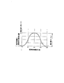
すなわち、図1および図3を参照して、センタレス研削盤の構成要素として実際に装置に組み込まれた調整車2の外周面2aの回転精度は、前述した各種要因により一般的に数マイクロメータ存在しており、このため、調整車外周面2aにおける回転振れがあり、これを完全に除去することは困難である。
【0036】
一方、ワークWの最終仕上がり寸法は、連続回転する調整車2の回転位置には関係なく、研削砥石車1のワークWに対する切込み送りの前進端位置を設定することによって段取りされているため、ワークWと接する調整車2の回転位置(向き)が変われば、最大で調整車外周面2aの振れ量(調整車2表面と研削砥石車1表面の最大間隔寸法(S1)−調整車2表面と研削砥石車1表面の最小間隔寸法(S2))だけ、ワークWの最終仕上がり寸法も変化することになる。
【0037】
一般的に、研削砥石車1の研削送りつまり切込み送りは、切込み送り部8により、研削砥石車1と調整車2間の間隔Aを狭くする方向に与えられる。
【0038】
したがって、本実施形態の制御装置4においては、調整車2の回転と研削送りを数値制御軸として、この2軸の同時制御を行うように、つまり、調整車2の回転と研削砥石車1の切込み送りを同期させて制御を行うように構成されている。
【0039】
これにより、上記研削送り位置と調整車2とワークWの接する位置の関係がいつも一定となり、ワークWの最終仕上り寸法を決定する研削送りの前進端位置において、ワークWに対する調整車2の位置(向き)は毎回同じに保たれる。この結果、たとえ調整車2に上述したような回転振れがあっても、調整車2表面と研削砥石車1表面の間の距離S1 ,S2 はいつも一定となり、ワークWの仕上り寸法も一定となって寸法バラツキがなくなることになる。
【0040】
この目的のため、調整車2の調整車軸6には、調整車2の回転位置を検出するロータリエンコーダ等の回転位置検出器(回転位置検出手段)10が設けられるとともに、調整車2とブレード3が装着された前記調整車基台または切込み送り部8には、研削砥石車1の切込み送り位置を間接的に検出するラインエンコーダ等の切込み送り位置検出器(切込み送り位置検出手段)11が設けられており、これら検出器10,11は、電気的に制御装置4に接続されている。
【0041】
そして、制御装置4には上記両検出器10、11の検出結果が常時入力されて、これにより制御装置4は、上記回転位置検出器10と切込み送り位置検出器11からの検出結果に応じて、調整車駆動部7の駆動モータと切込み送り部8の駆動モータを駆動制御することとなる。また、制御装置4は、調整車2の回転速度が研削サイクルにおける各研削工程に応じた値になるように、調整車駆動部7の駆動モータと切込み送り部8の駆動モータを駆動制御する。
【0042】
しかして、以上のように構成されたセンタレス研削盤において、ワークWは、ブレード3と調整車2により回転支持されながら、調整車2により切込み送りされ、つまり、高速回転する研削砥石車1が、切込み送り部8によりワークWに対して相対的に切込み送りして、ワークW外周面にインフィード方式により研削加工が施される。
【0043】
この場合、調整車外周面2aには回転振れを生じているところ、調整車2の回転位置と研削砥石車1のワークWに対する切込み送りとが同期して制御されることにより、調整車外周面2aの回転振れが有効に相殺除去されて、研削砥石車1の切込み送り位置と、調整車2とワークWの接する位置との関係が常時一定となる。この結果、ワークWの仕上り寸法は寸法のバラツキなく常時一定となり、高い加工精度をもってワークWの外周面を研削することができる。
【0044】
実施形態2
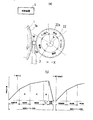
本実施形態は図5および図6に示されており、量産品としての小径のワーク外径をインフィード研削する場合に適した構成を備えるものである。
【0045】
本実施形態のセンタレス研削盤においては、図5(a) に示すように、調整車12が、回転支持すべきワークWに対応した幅寸法を有する外周面(円筒支持面)12aを有するとともに、この外周面12aの所定位置にワークW排出用のワーク収容ポケット13を備えた構造とされている。
【0046】
また、制御装置4は、図5(b) に示すように、調整車12が1回転する間にワークWの外周面に対する1研削サイクルを行うとともに、この研削サイクル終了時にワークWをワークW収容ポケットに収容して排出すべく、上記調整車駆動部7と切込み送り部8を駆動制御するように構成されている。
【0047】
しかして、以上のように構成されたセンタレス研削盤は、図5(b) および図6における研削サイクルの各研削工程(▲1▼〜▲5▼)を自動で順次連続して実行して、量産品としての小径のワークWの外周面をインフィード研削する。
【0048】
すなわち、i)ワークWの所定研削位置への投入供給(図6の▲1▼参照)→ii) 租研削工程(図6の▲2▼参照)→iii)精研削工程(図6の▲3▼参照)→iv) スパークアウト(図6の▲4▼参照)→v)ワークWのワーク収容ポケット13への収容排出(図6の▲5▼参照)の各研削工程からなる研削サイクルが、調整車12が1回転する間に行われる。
【0049】
なお、上記研削工程i)におけるワークWの供給は、研削砥石車1および調整車12の軸方向前後のいずれかの側からブレード3上に投入されるか、あるいは、研削砥石車1および調整車12間の上部からローダ装置によりブレード3上に載置される。
【0050】
また、上記研削工程v) においてワーク収容ポケット13へ収容排出されたワークWは、次のワークWの研削サイクルにおける精研削工程iii)で、装置外部へ落下排出されて収容される(図6の▲3▼参照)。
【0051】
本実施形態のような構成・方式とすることにより、調整車2として、従来一般の調整車と同様、調整車2の外周面がその回転中心と同心円のものが採用可能となり、前述した従来の渦巻き形状の外周面を備える調整車を用いた研削方式において存在していた問題点がすべて解消され得る。
【0052】
つまり、(a) 調整車12の外周面12aが円筒面であるとともに、調整車2の回転と研削砥石車1の切込み送りを同期させて制御する構成であるから、調整車2の回転位置にあわせた任意の切込み送り量が設定でき、研削量等の研削条件を変更する場合にも、調整車2の外周面の形状を変更するための成形が容易または不要である、(b) よって、調整車12の外周面形状を成形する成形装置は従来一般の構造のものでよい、および(c) 調整車12の回転速度が1回転の間で任意に設定でき、自由に研削条件の設定変更が可能である、等の利点がある。
その他の構成および作用は実施形態1と同様である。
【0053】
実施形態3
本実施形態は図7および図8に示されており、実施形態2の構成が若干改変されたものである。
【0054】
本実施形態のセンタレス研削盤においては、図7(a) に示すように、調整車22が、実施形態2と同様、回転支持すべきワークWに対応した幅寸法を有する外周面(円筒支持面)22aを有する。
【0055】
また、制御装置4は、図7(b) に示すように、調整車22が1回転または複数回転(図示の実施形態においては1回転)する間にワークWの外周面に対する1研削サイクルを行うとともに、この研削サイクル終了時に調整車22を後退させて、この調整車22と上記ブレード3との間にワークWを落下させて排出すべく、上記調整車駆動部7と切込み送り部8を駆動制御するように構成されている。
【0056】
しかして、以上のように構成されたセンタレス研削盤は、図7(b) および図8における研削サイクルの各研削工程(▲1▼〜▲5▼)を自動で順次連続して実行して、実施形態2と同様、量産品としての小径のワークWの外周面をインフィード研削する。
【0057】
すなわち、i)ワークWの所定研削位置への投入供給(図8の▲1▼参照)→ii) 租研削工程(図8の▲2▼参照)→iii)精研削工程(図8の▲3▼参照)→iv) スパークアウト(図8の▲4▼参照)→v)調整車22の後退による、ワークWの調整車22とブレード3間への落下排出(図8の▲5▼参照)の各研削工程からなる研削サイクルが、調整車22が1回転する間に行われる。
【0058】
本実施形態のようなワーク収容ポケットの存在しない構成とすることにより、1研削サイクル中に、調整車22を2回転あるいは3回転など複数回転するように構成することも可能であり、実施形態2に比較して、設計条件等をより柔軟に変更することが可能となる。
その他の構成および作用は実施形態1と同様である。
【0059】
なお、上述した実施形態1〜3は、あくまでも本発明の好適な実施態様を示すものであって、本発明はこれに限定されることなく、その範囲内において種々設計変更可能である。以下にその一例を示す。
【0060】
(1) 図示の実施形態においては、調整車2の調整車軸6に回転位置検出器10が設けられるとともに、前記調整車基台または切込み送り部8に切込み送り位置検出器11が設けられて、これら検出器10,11の検出結果が制御装置4に常時入力される構成とされているが、簡易的に、調整車2の調整車軸6の回転方向に位置センサが設けられて、研削送り開始時期をこの位置センサと同期させて、図示の実施形態と同程度の効果を得る方法も採用可能である。
【0061】
(2) 実施形態2において、ワークW排出用のワーク収容ポケット13が、調整車12の外周面12aに2箇所設けられても良く、この場合は、調整車12の1直径線上位置に一対のワーク収容ポケット13、13が対向して設けられるとともに、調整車12が半回転する間にワークWの外周面に対する1研削サイクルが行われることとなる。
【0062】
(3) センタレス研削盤の他の基本構造については、研削対象の形状寸法に応じて従来周知のすべての構造が採用可能である。
【0063】
(4) また、研削砥石車1自体が切込み送り動作を行う構造としてもよい。この場合は、砥石車台自体が切込み方向へ移動可能とされる。
【0064】
【発明の効果】
以上詳述したように、本発明によれば、調整車の回転位置と研削砥石車のワークに対する切込み送りとを同期させて、ワークの円筒外周面をセンタレス研削するようにしたから、たとえ調整車外周面に回転振れがあっても、高い加工精度をもってワーク外周面を研削することができる。
【0065】
また、本発明の研削方法を、高い生産性が要求される量産品としての小径ワーク外周面のインフィード研削に適用することにより、調整車として、従来一般の調整車と同様、調整車外周面がその回転中心と同心円のものが採用可能となり、従来の渦巻き形状の外周面を備える調整車を用いた研削方式において存在していた問題点を有効に解消し得る。
【図面の簡単な説明】
【図1】本発明の実施形態1に係るセンタレス研削盤を示す概略構成図である。
【図2】同センタレス研削盤における制御の主要構成を示すブロック線図である。
【図3】同センタレス研削盤における調整車に存在する1回転当たりの回転振れを示す線図である。
【図4】同センタレス研削盤における研削サイクルを示す線図である。
【図5】本発明の実施形態2に係るセンタレス研削盤を示し、図5(a) は同センタレス研削盤の概略構成を示す図、図5(b) は同センタレス研削盤における研削サイクルを示す線図である。
【図6】同センタレス研削盤によるインフィード研削を説明するための研削工程図である。
【図7】本発明の実施形態3に係るセンタレス研削盤を示し、図7(a) は同センタレス研削盤の概略構成を示す図、図7(b) は同センタレス研削盤における研削サイクルを示す線図である。
【図8】同センタレス研削盤によるインフィード研削を説明するための研削工程図である。
【符号の説明】
W ワーク
1 研削砥石車
1a 砥石面
2 調整車
2a 調整車外周面
3 ブレード
4 制御装置(制御手段)
7 調整車駆動部(調整車駆動手段)
8 切込み送り部(切込み送り手段)
10 回転位置検出器(回転位置検出手段)
11 切込み送り位置検出器(切込み送り位置検出手段)
12 調整車
12a 調整車外周面
13 ワーク収容ポケット
22 調整車
22a 調整車外周面[0001]
BACKGROUND OF THE INVENTION
The present invention relates to a centerless grinding method and a centerless grinding machine, and more specifically, a rotating grinding wheel is relatively cut and fed to a rotationally supported workpiece to grind a cylindrical outer peripheral surface of the workpiece. The present invention relates to in-feed centerless grinding technology.
[0002]
[Prior art]
In-feed (cut feed) grinding in a centerless grinding machine is performed by using a grinding wheel that rotates at high speed with respect to a work piece (hereinafter referred to as a workpiece) supported by a blade (receiving plate) and an adjustment wheel. The workpiece is relatively cut and fed to grind the outer peripheral surface of the workpiece.
[0003]
The final finished dimension of the workpiece in this in-feed grinding is determined by the advance end position of the cutting feed with respect to the workpiece of the grinding wheel.
[0004]
Here, the adjustment wheel used in the centerless grinding machine controls the rotation speed of the workpiece, supports the workpiece with the blade, and plays an important role in determining the final finished dimension (machining accuracy) of the workpiece. Therefore, the outer peripheral surface of the adjusting wheel that becomes the support surface of the workpiece is configured to ensure high rotational accuracy (runout accuracy).
[0005]
[Problems to be solved by the invention]
However, the recent demands for machining accuracy are severe, and there has been a situation where the conventional infeed type centerless grinding technology cannot sufficiently cope.
[0006]
That is, even in an adjustment wheel configured with high rotation accuracy as described above, the rotation accuracy of the outer surface of the adjustment wheel that is actually incorporated in the device as a component of the centerless grinding machine is generally several micrometers. For this reason, there is rotational runout on the outer peripheral surface of the adjusting wheel, and it is difficult to completely remove this.
[0007]
More specifically, rotational runout caused by an adjustment axle on which the adjustment wheel is mounted and a bearing that supports the adjustment wheel, molding accuracy by the correction device for the outer periphery of the adjustment wheel, deformation due to heat after entering the grinding operation, or Due to a misalignment between the adjusting axle and the adjusting wheel due to grinding resistance, rotational fluctuation of the outer peripheral surface of the adjusting wheel occurs.
[0008]
On the other hand, the final finished dimension of the workpiece is set by setting the advance end position of the cutting feed with respect to the workpiece of the grinding wheel regardless of the position in the rotation direction of the adjustment wheel (hereinafter referred to as the rotation position) that continuously rotates. For this reason, if the rotational position of the adjusting wheel in contact with the workpiece changes, the workpiece final finished size also changes by the amount of deflection of the adjusting vehicle.
[0009]
In this way, the rotational runout on the outer peripheral surface of the adjusting wheel affects the machining accuracy of the workpiece. However, with the conventional infeed type centerless grinding technology, there is a situation where the recent severe machining accuracy requirements cannot be met. Development of new centerless grinding technology has been demanded.
[0010]
Also, when infeed grinding a small workpiece outer diameter as a mass-produced product with a centerless grinder, productivity is regarded as important rather than machining accuracy. As a grinding method for grinding such mass-produced products, Adjusting wheel by using an adjusting wheel provided with a spiral outer peripheral surface (an outer peripheral surface whose diameter dimension continuously changes (increases) at a constant rate) and a work receiving pocket is provided at the position of the maximum outer diameter. A grinding method is adopted in which plunge grinding is performed on the outer peripheral surface of the workpiece during one rotation at a constant rotation speed, and the workpiece is accommodated and discharged after the grinding cycle is completed. Has been.
[0011]
However, as described above, in recent times when the required level of machining accuracy has become stricter, there is still a situation in which such a grinding method cannot be satisfied.
[0012]
In particular, the problems with this grinding method are: i) When changing the grinding conditions such as the grinding amount, it is necessary to re-form in order to change the shape of the outer peripheral surface of the adjusting wheel, which takes time. Ii) The shaping device for forming the outer peripheral surface shape of the adjusting wheel is complicated, and iii) The rotational speed of the adjusting wheel is constant, so that the setting of grinding conditions cannot be freely changed.
[0013]
The present invention has been made in view of such conventional problems, and the object of the present invention is to achieve high machining accuracy even in the case of rotational runout on the outer peripheral surface of the adjusting wheel in in-feed type centerless grinding. An object of the present invention is to provide a centerless grinding technique that can grind the outer peripheral surface of a workpiece and is also optimal for grinding a small-diameter workpiece outer diameter as a mass-produced product requiring high productivity.
[0014]
[Means for Solving the Problems]
In order to achieve the above object, the centerless grinding method according to the present invention cuts and feeds a rotating grinding wheel relative to a work rotatably supported by a backing plate and an adjustment wheel, thereby providing a cylindrical outer peripheral surface of the work. An in-feed centerless grinding method for grinding, characterized in that a cylindrical outer peripheral surface of a workpiece is ground by synchronizing a rotational position of the adjusting wheel and a cutting feed to the workpiece of the grinding wheel.
[0015]
The centerless grinding machine of the present invention is an optimum apparatus for carrying out the centerless grinding method, and includes an adjusting wheel driving means for rotating the adjusting wheel and a grinding wheel for cutting relative to the workpiece. A cutting feed means for feeding, a rotational position detecting means for detecting the rotational position of the adjusting wheel, a cutting feed position detecting means for detecting the cutting feed position of the grinding wheel, the adjusting wheel driving means and the cutting feed means. Control means for controlling driving in conjunction with each other, and the control means controls driving of the adjusting vehicle driving means and the cutting feed means in accordance with detection results from the rotational position detection means and the cutting feed position detection means. Thus, the rotational position of the adjusting wheel and the cutting feed to the workpiece of the grinding wheel are synchronized.
[0016]
In addition to the normal adjustment wheel that has a cylindrical outer peripheral surface that is continuous over the entire circumference, the adjustment wheel is suitable for grinding the outer diameter of a small workpiece as a mass-produced product. An adjustment car with a pocket is adopted.
[0017]
As a preferred embodiment, the rotational speed of the adjusting wheel is set according to each grinding step in the grinding cycle.
[0018]
In the present invention, by synchronizing the rotational position of the adjustment wheel and the cutting feed to the workpiece of the grinding wheel and centerless grinding of the cylindrical outer peripheral surface of the workpiece, even if there is rotational runout on the outer peripheral surface of the adjustment wheel, The workpiece outer peripheral surface can be ground with high machining accuracy.
[0019]
That is, in general, the grinding feed, that is, the cutting feed, is given in the direction of narrowing the interval between the grinding wheel and the adjusting wheel by the above-mentioned cutting feed means. In the present invention, by controlling the rotation of the adjusting wheel and the cutting feed of the grinding wheel in synchronization, the relationship between the cutting feed position of the grinding wheel and the position where the adjusting wheel is in contact with the workpiece is always constant. .
[0020]
Therefore, in the cutting feed advance end position of the grinding wheel that determines the final finished dimensions of the workpiece, the rotational position of the adjustment wheel relative to the workpiece is kept the same every time, so even if there is rotational runout on the outer peripheral surface of the adjustment wheel, The distance between the cutting feed position of the grinding wheel and the position where the adjusting wheel and the workpiece are in contact with each other is always constant. As a result, the finished dimension of the workpiece is also constant and there is no dimensional variation.
[0021]
In addition, when infeed grinding a small workpiece outer diameter as a mass-produced product with a centerless grinding machine, the rotation position of the adjusting wheel and the cutting feed to the workpiece of the grinding wheel are synchronized, and the following two methods are adopted. Can be done.
[0022]
i) As the adjustment wheel, an adjustment wheel provided with a work storage pocket for discharging a workpiece at a predetermined position on the outer peripheral surface is used, and one grinding cycle is performed on the outer peripheral surface of the work while the adjustment wheel makes one rotation. At the end of the grinding cycle, the workpiece is stored in the workpiece storage pocket and discharged.
[0023]
ii) As the adjusting wheel, a normal adjusting wheel having a cylindrical outer peripheral surface continuous over the entire circumference is used, and one grinding cycle is performed on the outer peripheral surface of the workpiece while the adjusting wheel is rotated once or a plurality of times. At the end of the grinding cycle, the adjusting wheel is moved backward, and the work is dropped between the adjusting wheel and the receiving plate and discharged.
[0024]
With such a system, as the adjustment vehicle, it is possible to adopt an adjustment wheel whose outer peripheral surface is concentric with the center of rotation as in the case of a conventional adjustment wheel, and grinding using the adjustment wheel having the spiral outer periphery described above. Problems existing in the method can be solved.
[0025]
DETAILED DESCRIPTION OF THE INVENTION
Hereinafter, embodiments of the present invention will be described with reference to the drawings.
[0026]
A centerless grinding machine according to the present invention is shown in FIGS. 1 and 2. Specifically, this grinding machine is a centerless grinding machine for grinding a cylindrical outer peripheral surface of a workpiece W by an infeed method, and includes a grinding wheel. The basic configuration of the
[0027]
The
[0028]
The
[0029]
The
[0030]
The adjusting wheel base on which the
[0031]
This cutting feed
[0032]
The
[0033]
In addition, the
[0034]
Specifically, in consideration of the presence of rotational runout on the outer
[0035]
That is, referring to FIG. 1 and FIG. 3, the rotational accuracy of the outer
[0036]
On the other hand, the final finished dimension of the workpiece W is set by setting the forward end position of the cutting feed with respect to the workpiece W of the
[0037]
In general, the grinding feed of the
[0038]
Therefore, in the
[0039]
As a result, the relationship between the grinding feed position and the position where the
[0040]
For this purpose, the
[0041]
And the detection result of both the said
[0042]
Thus, in the centerless grinding machine configured as described above, the workpiece W is cut and fed by the
[0043]
In this case, when the adjustment wheel outer
[0044]
This embodiment is shown in FIGS. 5 and 6 and has a configuration suitable for in-feed grinding of a small workpiece outer diameter as a mass-produced product.
[0045]
In the centerless grinding machine of the present embodiment, as shown in FIG. 5 (a), the
[0046]
Further, as shown in FIG. 5 (b), the
[0047]
Thus, the centerless grinding machine configured as described above automatically and sequentially executes each grinding step ((1) to (5)) of the grinding cycle in FIG. 5 (b) and FIG. Infeed grinding is performed on the outer peripheral surface of a small-diameter workpiece W as a mass-produced product.
[0048]
That is, i) input and supply of the workpiece W to a predetermined grinding position (see (1) in FIG. 6) → ii) pre-grinding process (see (2) in FIG. 6) → iii) fine grinding process ((3) in FIG. 6) ▼) → iv) Sparking out (see (4) in FIG. 6) → v) Grinding cycle consisting of each grinding step of receiving and discharging the workpiece W into the workpiece storage pocket 13 (see (5) in FIG. 6) This is performed while the
[0049]
The workpiece W in the grinding step i) is supplied onto the
[0050]
In addition, the workpiece W accommodated and discharged in the
[0051]
By adopting the configuration and method as in the present embodiment, it is possible to adopt a vehicle having the outer peripheral surface of the
[0052]
That is, (a) the outer
Other configurations and operations are the same as those of the first embodiment.
[0053]
This embodiment is shown in FIG. 7 and FIG. 8, and the configuration of the second embodiment is slightly modified.
[0054]
In the centerless grinding machine of the present embodiment, as shown in FIG. 7 (a), the adjusting
[0055]
Further, as shown in FIG. 7 (b), the
[0056]
Thus, the centerless grinding machine configured as described above automatically and sequentially executes each grinding step ((1) to (5)) of the grinding cycle in FIG. 7 (b) and FIG. As in the second embodiment, the outer peripheral surface of a small-diameter workpiece W as a mass-produced product is in-feed ground.
[0057]
That is, i) input and supply of the workpiece W to a predetermined grinding position (see (1) in FIG. 8) → ii) pre-grinding process (see (2) in FIG. 8) → iii) fine grinding process ((3) in FIG. 8) (See ▼) → iv) Spark out (See (4) in FIG. 8) → v) Discharge of workpiece W between adjusting
[0058]
By adopting a configuration in which there is no workpiece accommodation pocket as in the present embodiment, it is possible to configure the
Other configurations and operations are the same as those of the first embodiment.
[0059]
In addition, Embodiment 1-3 mentioned above shows the suitable embodiment of this invention to the last, This invention is not limited to this, A various design change is possible within the range. An example is shown below.
[0060]
(1) In the illustrated embodiment, a
[0061]
(2) In the second embodiment, the work storage pockets 13 for discharging the work W may be provided at two locations on the outer
[0062]
(3) As for the other basic structure of the centerless grinding machine, any conventionally known structure can be adopted according to the shape and dimension of the object to be ground.
[0063]
(4) Moreover, it is good also as a structure where the
[0064]
【The invention's effect】
As described above in detail, according to the present invention, since the rotational position of the adjusting wheel and the cutting feed to the workpiece of the grinding wheel are synchronized, the cylindrical outer peripheral surface of the workpiece is centerless ground. Even if there is rotational runout on the outer peripheral surface, the work outer peripheral surface can be ground with high machining accuracy.
[0065]
Further, by applying the grinding method of the present invention to in-feed grinding of the outer peripheral surface of a small-diameter workpiece as a mass-produced product that requires high productivity, the outer peripheral surface of the adjusting vehicle is the same as the conventional adjusting vehicle. However, a concentric circle with the center of rotation can be adopted, and the problems existing in the conventional grinding method using the adjusting wheel having the spiral outer peripheral surface can be effectively solved.
[Brief description of the drawings]
FIG. 1 is a schematic configuration diagram showing a centerless grinding machine according to a first embodiment of the present invention.
FIG. 2 is a block diagram showing a main configuration of control in the centerless grinding machine.
FIG. 3 is a diagram showing rotational runout per rotation existing in the adjustment wheel in the centerless grinding machine.
FIG. 4 is a diagram showing a grinding cycle in the centerless grinding machine.
5 shows a centerless grinding machine according to
FIG. 6 is a grinding process diagram for explaining in-feed grinding by the centerless grinding machine.
7 shows a centerless grinding machine according to
FIG. 8 is a grinding process diagram for explaining in-feed grinding by the centerless grinding machine.
[Explanation of symbols]
7 Adjustment vehicle drive (adjustment vehicle drive means)
8 Cutting feed section (cutting feed means)
10 Rotation position detector (Rotation position detection means)
11 Cutting feed position detector (cutting feed position detection means)
12
Claims (6)
前記調整車の回転位置と前記研削砥石車の工作物に対する切込み送りとを同期させて、工作物の円筒外周面を研削する
ことを特徴とするセンタレス研削方法。A centerless grinding method of an infeed method in which a rotating grinding wheel is relatively cut and fed to a workpiece rotatably supported by a receiving plate and an adjustment wheel, and the cylindrical outer peripheral surface of the workpiece is ground.
A centerless grinding method for grinding a cylindrical outer peripheral surface of a workpiece by synchronizing a rotational position of the adjusting wheel and a cutting feed to the workpiece of the grinding wheel.
ことを特徴とする請求項1に記載のセンタレス研削方法。The centerless grinding method according to claim 1, wherein the rotation speed of the adjusting wheel is set according to each grinding step in a grinding cycle.
調整車を回転駆動する調整車駆動手段と、
研削砥石車を工作物に対して相対的に切込み送りする切込み送り手段と、
前記調整車の回転位置を検出する回転位置検出手段と、
前記研削砥石車の切込み送り位置を検出する切込み送り位置検出手段と、
前記調整車駆動手段と切込み送り手段を相互に連動して駆動制御する制御手段とを備え、
この制御手段は、前記回転位置検出手段と切込み送り位置検出手段からの検出結果に応じて、前記調整車駆動手段と切込み送り手段を駆動制御し、これにより、前記調整車の回転位置と前記研削砥石車の工作物に対する切込み送りとを同期させるように構成されている
ことを特徴とするセンタレス研削盤。An infeed type centerless grinding machine that relatively cuts and feeds a rotating grinding wheel relative to a work piece supported by a receiving plate and an adjustment wheel, and grinds a cylindrical outer peripheral surface of the work piece,
Adjusting vehicle driving means for rotationally driving the adjusting vehicle;
A cutting feed means for cutting and feeding the grinding wheel relative to the workpiece;
Rotational position detection means for detecting the rotational position of the adjusting wheel;
A cutting feed position detecting means for detecting a cutting feed position of the grinding wheel,
Control means for driving and controlling the adjusting vehicle driving means and the cutting feed means in conjunction with each other,
The control means drives and controls the adjusting vehicle driving means and the cutting feed means according to detection results from the rotational position detecting means and the cutting feed position detecting means, whereby the rotating position of the adjusting wheel and the grinding wheel are controlled. A centerless grinding machine characterized by being configured to synchronize cutting feed to a workpiece of a grinding wheel.
前記制御手段は、前記調整車が1回転する間に工作物の外周面に対する1研削サイクルを行うとともに、この研削サイクル終了時に工作物を前記ワーク収容ポケットに収容して排出するように、前記調整車駆動手段と切込み送り手段を駆動制御する
ことを特徴とする請求項3に記載のセンタレス研削盤。The adjusting wheel includes a workpiece storage pocket for discharging a workpiece at a predetermined position on the outer peripheral surface,
The control means performs one grinding cycle on the outer peripheral surface of the workpiece while the adjustment wheel makes one rotation, and at the end of the grinding cycle, the adjustment is performed so that the workpiece is accommodated in the workpiece accommodation pocket and discharged. 4. The centerless grinding machine according to claim 3, wherein drive control of the vehicle driving means and the cutting feed means is performed.
前記制御手段は、前記調整車が1回転または複数回転する間に工作物の外周面に対する1研削サイクルを行うとともに、この研削サイクル終了時に前記調整車を後退させて、この調整車と前記受板との間に工作物を落下させて排出するように、前記調整車駆動手段と切込み送り手段を駆動制御する
ことを特徴とする請求項3に記載のセンタレス研削盤。The adjustment wheel includes a cylindrical outer peripheral surface,
The control means performs one grinding cycle on the outer peripheral surface of the workpiece while the adjusting wheel is rotated once or a plurality of times, and retracts the adjusting wheel at the end of the grinding cycle so that the adjusting wheel and the receiving plate 4. The centerless grinding machine according to claim 3, wherein the adjustment wheel drive means and the cutting feed means are driven and controlled so that the workpiece is dropped and discharged therebetween.
ことを特徴とする請求項3から5のいずれか一つに記載のセンタレス研削盤。The said control means drives and controls the said adjustment wheel drive means and a cutting feed means so that the rotational speed of the said adjustment wheel becomes a value according to each grinding process in a grinding cycle. The centerless grinding machine according to any one of the above.
Priority Applications (1)
| Application Number | Priority Date | Filing Date | Title |
|---|---|---|---|
| JP22800599A JP3815130B2 (en) | 1999-08-11 | 1999-08-11 | Centerless grinding method and centerless grinding machine |
Applications Claiming Priority (1)
| Application Number | Priority Date | Filing Date | Title |
|---|---|---|---|
| JP22800599A JP3815130B2 (en) | 1999-08-11 | 1999-08-11 | Centerless grinding method and centerless grinding machine |
Publications (3)
| Publication Number | Publication Date |
|---|---|
| JP2001054842A JP2001054842A (en) | 2001-02-27 |
| JP2001054842A5 JP2001054842A5 (en) | 2005-04-07 |
| JP3815130B2 true JP3815130B2 (en) | 2006-08-30 |
Family
ID=16869695
Family Applications (1)
| Application Number | Title | Priority Date | Filing Date |
|---|---|---|---|
| JP22800599A Expired - Fee Related JP3815130B2 (en) | 1999-08-11 | 1999-08-11 | Centerless grinding method and centerless grinding machine |
Country Status (1)
| Country | Link |
|---|---|
| JP (1) | JP3815130B2 (en) |
Cited By (1)
| Publication number | Priority date | Publication date | Assignee | Title |
|---|---|---|---|---|
| CN104385070A (en) * | 2014-09-30 | 2015-03-04 | 潘旭华 | Numerical control centerless grinding machine |
-
1999
- 1999-08-11 JP JP22800599A patent/JP3815130B2/en not_active Expired - Fee Related
Cited By (1)
| Publication number | Priority date | Publication date | Assignee | Title |
|---|---|---|---|---|
| CN104385070A (en) * | 2014-09-30 | 2015-03-04 | 潘旭华 | Numerical control centerless grinding machine |
Also Published As
| Publication number | Publication date |
|---|---|
| JP2001054842A (en) | 2001-02-27 |
Similar Documents
| Publication | Publication Date | Title |
|---|---|---|
| WO1997003391A1 (en) | Improvements in and relating to machine tools | |
| JP3815130B2 (en) | Centerless grinding method and centerless grinding machine | |
| GB2226783A (en) | Double-end surface grinding machine | |
| JP2003503215A (en) | Method and apparatus for feeding a tool holder rotating about a rotationally symmetric structural part | |
| JPH0632894B2 (en) | Cam grinding equipment | |
| EP0950214B1 (en) | Method of controlling a machine tool | |
| JP3903611B2 (en) | Centerless grinding machine and workpiece machining method | |
| JP3112408B2 (en) | Vertical double-ended surface grinder | |
| JP3870000B2 (en) | Centerless grinding method and grinding apparatus | |
| JPH05123949A (en) | Centerless grinding machine | |
| JP2004082300A (en) | Dressing method of grinding wheel in centerless grinder and dressing device | |
| US4891914A (en) | Computer controlled universal grinder and method for grinding trochoidal and circular bearing races | |
| JP3412507B2 (en) | Gear honing machine | |
| JP2020203344A (en) | Grinding method by centerless grinder and centerless grinder | |
| JPH10249686A (en) | Cylindrical grinding machine and grinding method of crankshaft | |
| JP2001328067A (en) | Grinding method in cylindrical grinding panel | |
| JPH06114731A (en) | Grinding wheel truing device | |
| JPH11226855A (en) | Internal periphery spherical surface grinding method for workpiece | |
| EP0336312A2 (en) | Computer controlled universal grinder and method for grinding hypotrochoidal, epitrochoidal and circular bearing races | |
| JPS60213472A (en) | Grinder | |
| JPS61274865A (en) | Profile grinding machine | |
| JP3682832B2 (en) | Non-circular workpiece processing equipment | |
| JPS61103770A (en) | Cam grinding apparatus | |
| JP3107481B2 (en) | Centerless grinding method and apparatus for stepped workpiece | |
| JPS6350143B2 (en) |
Legal Events
| Date | Code | Title | Description |
|---|---|---|---|
| A521 | Written amendment |
Free format text: JAPANESE INTERMEDIATE CODE: A523 Effective date: 20040531 |
|
| A621 | Written request for application examination |
Free format text: JAPANESE INTERMEDIATE CODE: A621 Effective date: 20040531 |
|
| TRDD | Decision of grant or rejection written | ||
| A01 | Written decision to grant a patent or to grant a registration (utility model) |
Free format text: JAPANESE INTERMEDIATE CODE: A01 Effective date: 20060523 |
|
| A61 | First payment of annual fees (during grant procedure) |
Free format text: JAPANESE INTERMEDIATE CODE: A61 Effective date: 20060529 |
|
| R150 | Certificate of patent or registration of utility model |
Free format text: JAPANESE INTERMEDIATE CODE: R150 |
|
| FPAY | Renewal fee payment (event date is renewal date of database) |
Free format text: PAYMENT UNTIL: 20090616 Year of fee payment: 3 |
|
| FPAY | Renewal fee payment (event date is renewal date of database) |
Free format text: PAYMENT UNTIL: 20120616 Year of fee payment: 6 |
|
| FPAY | Renewal fee payment (event date is renewal date of database) |
Free format text: PAYMENT UNTIL: 20120616 Year of fee payment: 6 |
|
| FPAY | Renewal fee payment (event date is renewal date of database) |
Free format text: PAYMENT UNTIL: 20120616 Year of fee payment: 6 |
|
| FPAY | Renewal fee payment (event date is renewal date of database) |
Free format text: PAYMENT UNTIL: 20130616 Year of fee payment: 7 |
|
| FPAY | Renewal fee payment (event date is renewal date of database) |
Free format text: PAYMENT UNTIL: 20130616 Year of fee payment: 7 |
|
| R250 | Receipt of annual fees |
Free format text: JAPANESE INTERMEDIATE CODE: R250 |
|
| R250 | Receipt of annual fees |
Free format text: JAPANESE INTERMEDIATE CODE: R250 |
|
| LAPS | Cancellation because of no payment of annual fees |