JP3813603B2 - Inter-terminal communication connection control method using IP network - Google Patents
Inter-terminal communication connection control method using IP network Download PDFInfo
- Publication number
- JP3813603B2 JP3813603B2 JP2003313725A JP2003313725A JP3813603B2 JP 3813603 B2 JP3813603 B2 JP 3813603B2 JP 2003313725 A JP2003313725 A JP 2003313725A JP 2003313725 A JP2003313725 A JP 2003313725A JP 3813603 B2 JP3813603 B2 JP 3813603B2
- Authority
- JP
- Japan
- Prior art keywords
- telephone
- terminal
- communication
- network
- packet
- Prior art date
- Legal status (The legal status is an assumption and is not a legal conclusion. Google has not performed a legal analysis and makes no representation as to the accuracy of the status listed.)
- Expired - Fee Related
Links
Images


Description
本発明は、IP網(IP通信網ともいう)及び無線LANに接続する端末がIP網に接続して他の端末と通信できるようにすると共に、IP網に接続する移動電話機や音声画像装置がその地理的位置を移動しながらIP網を経由して継続し、ユーザ要求に基づいてアドレス情報を登録してある任意の端末間に通信パスを設定し、不正IPパケットのIP網内大量流入を防止するIP網を用いた端末間通信接続制御方法に関する。 The present invention enables a terminal connected to an IP network (also referred to as an IP communication network) and a wireless LAN to connect to the IP network and communicate with other terminals, and a mobile phone and a voice image apparatus connected to the IP network Continues via the IP network while moving its geographical location, sets a communication path between any terminals that have registered address information based on user requests, and causes a large inflow of illegal IP packets into the IP network The present invention relates to an inter-terminal communication connection control method using an IP network to be prevented.
本発明に関係する従来技術として、本出願人による特許第3084681号(特許文献1)と、本出願人による特願2002−164497(特許文献2)とがある。 As conventional techniques related to the present invention, there are Japanese Patent No. 3084861 (Patent Document 1) by the present applicant and Japanese Patent Application No. 2002-164497 (Patent Document 2) by the present applicant.
特許文献1は、IPカプセル化の技法を採用したIPパケット転送網である統合情報通信システムにおいて、IPカプセル化の技法、電話番号をドメイン名サーバに提示してIPアドレスを取得し電話通信する方法などを実現している。
<<カプセル化の技法(特許文献1)>>
図144において、1はIP網、2及び3は網ノード装置、5乃至8はLAN,10及び11は端末、15(図145)及び16(図146)は装置制御表である。端末10はアドレス“E1”を有し、端末11はアドレス“E2”を有する。
<< Encapsulation Technique (Patent Document 1) >>
144, 1 is an IP network, 2 and 3 are network node devices, 5 to 8 are LANs, 10 and 11 are terminals, and 15 (FIG. 145) and 16 (FIG. 146) are device control tables.
ソースアドレス“E1”、宛先アドレス“E2”である外部IPパケット17が通信回線12を経由して、通信回線の終端の論理端子を経て網ノード装置2に入力する。ここで、入側の論理端子には内部アドレス“I1”を付与してある。網ノード装置2は外部IPパケット17が入力すると、装置制御表15内の複数のレコード内から、次の(1)式の関係が成り立つレコード(カプセル制御レコード)(ただし、内部アドレス“I1”を含む)を順次探していく。ここで、ANDは論理演算のANDを表わし、“E1”及び“E2”は外部IPパケット17に含まれている外部アドレスである。“M1,N1,M2,N2”は装置制御表15内のレコードに含まれる。
( ("E1"
AND "M1") = "N1" ) AND ("E2" AND "M2")
= "N2") ) …(1)
内部パケット18はIP網1内を転送され、網ノード装置3に到達すると、装置制御表16の管理の基に復元されて外部パケット19となり、外部パケット19は、内部アドレス“I2”が付与されて通信回線14の終端の論理端子を経由し、次に通信回線14を経て端末11に送信される。
The
(("E1"
AND "M1") = "N1") AND ("E2" AND "M2")
= "N2"))… (1)
When the
なお、外部パケットの宛先アドレス“E2”が変わると、装置制御表15内の他のレコードについて前記(1)式が調べられ、内部パケット18の宛先が変わる(網ノード装置の交換機能)。なお、本発明において、装置制御表をカプセル制御表とも呼び、装置制御表のレコードをカプセル制御レコード若しくは通信レコードとも呼ぶ。
IP網を用い端末間通信接続制御方法を実施するために、(1)無線LANに接続する端末がIP網や移動通信網を経由して他の端末と通信すること、(2)IP網に接続する移動電話機や無線端末、可搬型の音声画像装置の地理的位置を移動しながら端末間通信を継続すること、(3)IP網に接続する任意の端末間において、2端末間の通信パス設定を許可すると共に、通信パス設定を拒否できるようになっている、IP網を用いた端末間通信接続続制御システムが存在していない。(4)未登録IPアドレスを含むIPパケットがIP網に大量流入して発生する網内輻輳や、DOS攻撃を防ぐ適当な方法がない。本発明は、これらの未解決の課題を解決することを目的とする。 In order to implement the inter-terminal communication connection control method using the IP network, (1) the terminal connected to the wireless LAN communicates with another terminal via the IP network or the mobile communication network, and (2) the IP network Continue communication between terminals while moving the geographical position of a mobile phone or wireless terminal to be connected or a portable audio image device, and (3) a communication path between two terminals between any terminals connected to the IP network. There is no inter-terminal communication connection control system using an IP network that permits setting and denies communication path setting. (4) There is no appropriate method for preventing intra-network congestion caused by a large amount of IP packets including unregistered IP addresses flowing into the IP network and DOS attacks. The present invention aims to solve these unsolved problems.
本発明は、(1)端末が無線LAN、IP網、移動通信網を経由して、他の電話機や無線端末、音声画像装置と通信するためにIP網内に認証サーバを設置し、無線LAN内部の端末に対する認証手続きを遂行することにより達成される。より詳しく述べると、無線LANは、無線LAN内のメディアルータ1から通信回線を経てIP網の網ノード装置の1つに接続し、無線LANは端末1を含み、端末2はメディアルータ2を経由してIP網の網ノード装置の1つに通信回線を経て接続し、端末登録表はメディアルータ1の内部に設定し、端末1から端末2に接続するときは、端末1が端末登録表の管理の基に発信許可を得る手順を含む通信接続制御を行うようにし、端末2から端末1に接続するときは、端末1が端末登録表の管理の基に着信許可を得る手順を含む通信接続制御を行うことも可能とすることにより、端末登録表の管理の基に端末1と端末2とが無線LANとIP網や移動通信網を経由して通信することができる。
In the present invention, (1) an authentication server is installed in the IP network so that the terminal communicates with other telephones, wireless terminals, and voice image devices via the wireless LAN, IP network, and mobile communication network. This is achieved by performing an authentication procedure for an internal terminal. More specifically, the wireless LAN is connected to one of the network node devices of the IP network via a communication line from the
また、他の実施方法として、端末登録表はメディアルータ1の内部に設置せず、認証付電話番号サーバ内部に設置し、メディアルータ1が認証付電話番号サーバを呼び出して端末登録表を用いるようにする。
As another implementation method, the terminal registration table is not installed in the
更に、(2)IP網に接続する移動電話機や可搬型の音声画像装置の地理的位置を移動しながら端末間通信を継続できるようにするために、IP網内部に設置する2以上の電話管理サーバの間で、移動電話機の地理的位置を変更するための一連の呼接続制御手順を実施することにより達成する。より詳しく述べると、IP網は、移動電話機1と移動電話機2との間の移動電話機間通信、移動電話機と固定電話機との間でIP網を経由して電話通信を行い、移動電話機は電話通信中に、少なくとも無線基地局を変えて電話通信を継続するというハンドオーバ通信を行う。ハンドオーバ通信を実施すると、移動後の電話機の位置情報である内部アドレスが、移動電話機専用の電話番号サーバ内部の移動電話機登録表のレコードとして書換えられるようにする。無線基地局1の無線通信領域1の範囲内にある移動電話機1が、移動電話機1−無線基地局1−終端ゲートウェイ1−終端ゲートウェイ2−無線基地局2−移動電話機2又は固定電話機2を経由して移動電話機2又は固定電話機2と電話通信を継続しながら、移動電話機1が終端ゲートウェイ3が管理する無線基地局3と通信する地理的位置に移動し、即ち移動電話機1−無線基地局3−終端ゲートウェイ3−終端ゲートウェイ2−無線基地局2−移動電話機2又は固定電話機2を経由し、移動電話機2又は固定電話機2と電話通信を継続する(ハンドオーバ)方法が基本となる電話通信継続方法である。
(3)端末の端末位置識別子、外部アドレス、端末をIP網に接続するための内部アドレスをIP網内のドメイン名サーバに登録しておき、一方の端末からの要求により、ドメイン名サーバに端末1及び端末2の端末位置識別子を提示して、端末1及び端末2に関連するアドレス情報(外部アドレスと内部アドレス)を取得し、端末1側の網ノード装置1内に通信レコード1を設定すると共に、端末2側の網ノード装置2内に通信レコード2を設定し、端末1と端末2との間でIPパケットを送受することができる。また、端末1乃至端末2からの要求により、前記設定した通信レコード1及び通信レコード2を抹消するようにする。
(4)端末のIPアドレスをIP網の通信回線接続部に登録しておき、通信回線接続部が、未登録のIPアドレスをソースアドレスとして含むIPパケットを検出すると、当該IPパケットを廃棄して不要IPパケットのIP網流入を防ぎ、IP網の通信輻輳を予防する。
Further, (2) two or more telephone managements installed in the IP network in order to continue communication between terminals while moving the geographical position of the mobile telephone connected to the IP network or the portable voice image device. This is accomplished by performing a series of call connection control procedures for changing the geographical location of the mobile telephone between servers. More specifically, the IP network performs inter-mobile telephone communication between the
(3) A terminal location identifier of the terminal, an external address, and an internal address for connecting the terminal to the IP network are registered in the domain name server in the IP network, and the terminal is connected to the domain name server in response to a request from one terminal. 1 and the terminal location identifiers of the
(4) The IP address of the terminal is registered in the communication line connection unit of the IP network, and when the communication line connection unit detects an IP packet including an unregistered IP address as a source address, the IP packet is discarded. This prevents unnecessary IP packets from flowing into the IP network and prevents communication congestion in the IP network.
本発明によれば、無線LANに接続する端末がIP網に接続して他の端末と通信できるようにするために、IP網内の電話番号サーバに登録済みの電話番号及びIPアドレスを含む端末登録表を無線LAN内のメディアルータ内に設置し、無線LAN内部の端末に対する認証手続きを遂行してIP網を用いた端末間通信接続制御方法を解決する方法を実現している。また、IP網に接続する移動電話機や無線端末,音声画像装置の地理的位置を移動しながらIP網を経由して端末間通信を継続するために、IP網内に2以上の電話管理サーバを設置し、電話機の地理的位置を変更するための一連の呼接続制御手順を実施してIP網を用いた端末間通信接続制御方法を解決する方法を実現している。 According to the present invention, a terminal including a telephone number and an IP address registered in a telephone number server in the IP network so that a terminal connected to the wireless LAN can connect to the IP network and communicate with other terminals. A registration table is installed in a media router in the wireless LAN, and an authentication procedure for a terminal in the wireless LAN is performed to solve the inter-terminal communication connection control method using the IP network. Also, two or more telephone management servers are installed in the IP network in order to continue communication between terminals via the IP network while moving the geographical location of the mobile phone, wireless terminal, and voice image device connected to the IP network. It implements a method of solving a terminal-to-terminal communication connection control method using an IP network by installing a series of call connection control procedures for changing the geographical position of a telephone.
更に、IP網に接続する任意の端末間において、2端末間の通信パス設定を許可すると共に通信パス設定を拒否できるようにし、IP網を用いた端末問通信接続続制御システムをそれぞれ提供するために、端末アドレス関連情報をIP網内サーバに登録しておき、2端末間の通信パスの設定許可は前記サーバ内の登録情報を用いて判定することにより、IP網を用いた端末間通信接続制御方法を解決する方法を実現している。 Further, to allow a communication path setting between two terminals between arbitrary terminals connected to the IP network and to reject the communication path setting, and to provide a terminal communication connection connection control system using the IP network, respectively. In addition, the terminal address related information is registered in the IP network server, and the communication path setting permission between the two terminals is determined using the registration information in the server, so that the inter-terminal communication connection using the IP network is performed. A method to solve the control method is realized.
また、端末IPアドレスをIP網に登録して、IPアドレス未登録IPパケットのIP網流入を防ぐ方法を実施している。 In addition, a method is implemented in which the terminal IP address is registered in the IP network to prevent the IP address unregistered IP packet from entering the IP network.
本発明は、特許文献1に開示されているIPカプセル化の技法、電話番号をドメイン名としてIPアドレスを取得する方法、特許文献2に開示されている固定電話、移動電話の実施方法に、更に新しい方法を導入することにより、(1)移動電話機や無線端末、音声画像装置が無線LAN、IP網、移動通信網を経由して、他の電話機や音声画像装置と通信するIP網を用いた端末間通信接続続制御システム、(2)IP網に接続する電話機や音声画像装置の地理的位置を移動しながら端末間通信を継続するIP網を用いた端末間通信接続続制御システム、(3)端末の端末位置識別子や端末をIP網内のドメイン名サーバに登録しておき、一方の端末からの要求により、IP網の内部に通信パスを設定して、端末1と端末2との間でIPパケット送受できるようにし、また端末の要求により通信パス設定を許可し又は拒否できるようにする、(4)端末のIPアドレスをIP網の通信回線接続部に登録しておき、IP網が、未登録のIPアドレスを含むIPパケットを廃棄することにより、不要IPパケットがIP網に流入することを防ぐことにより達成される。
The present invention relates to an IP encapsulation technique disclosed in
なお、本発明は特許文献2の実施例8に開示されているIP網を前提としているので、本発明の前提となるIP網として説明し、次に本発明を詳細に説明する。
<<本発明の前提となるIP網(特許文献2)>>
固定電話、移動電話、マルチメディア通信をいずれも実施可能であるIP網である。
Since the present invention is premised on the IP network disclosed in
<< IP network as a premise of the present invention (Patent Document 2) >>
It is an IP network that can implement all of fixed telephone, mobile telephone, and multimedia communication.
図1において、IP網900は終端ゲートウェイ901−1乃至901−5を含む。固定電話機905−1乃至905−4は、それぞれ有線通信回線を経由してメディアルータ903−1乃至903−4のいずれかに接続されており、移動電話機905−5乃至905−8はそれぞれ無線通信回線を経由して無線基地局902−1乃至902−4のいずれかに接続可能である。移動電話機905−5乃至905−8をいずれの無線基地局に接続するかは固定していない。メディアルータ及び無線基地局は、IPパケット転送機能を有する通信回線経由で網ノード装置のいずれかに接続されている。905−10乃至905−17はIPパケット送受機能を有する端末であり、それぞれ通信回線経由でメディアルータに接続されている。なお、図1は、特許文献2の実施例8(固定電話、移動電話、マルチメディア通信を同一IP網で実施)を説明する図92を含み、無線基地局902−5、移動後の移動電話機905−6y及び905−6z、移動電話機905−6の通話中移動905−21、他の通話中移動905−22を図92に追加している図である。従って、本発明の図1は、特許文献2の実施例8を実施可能である。
In FIG. 1, an
915はIP網900の運用管理サーバであり、通信回線を経てルータ911−1に接続されている。移動電話機は音声電話機、画像入出力機能付電話機或いは音声画像送受信装置や移動端末のいずれとすることも可能である。終端ゲートウェイ901−1は網ノード装置906−1、終端制御部914−1を含み、網ノード装置906−1は装置制御表910−1を含み、終端制御部914−1は代理電話サーバ906−2、表管理サーバ906−3、電話管理サーバ906−4、電話番号サーバ906−5、代理移動電話サーバ906−6、ルータ916−1を含む。サーバ906−2乃至906−5、網ノード装置906−1、ルータ916−1は通信回線で直接的又は間接的に接続している。同様に、終端ゲートウェイ901−2は網ノード装置907−1、終端制御部914−2を含み、網ノード装置907−1は装置制御表910−2を含み、終端制御部914−2は代理電話サーバ907−2、表管理サーバ907−3、電話管理サーバ907−4、電話番号サーバ907−5、代理移動電話サーバ907−6、ルータ916−2を含む。
An
通信ケース1,2,3,4,6に分けて説明する(通信ケース5を除く)。
<<通信ケース1:固定電話機と固定電話機との間の通信>>
図2は固定電話機905−1から固定電話機905−4への電話通信のための呼接続制御を説明する図であり、電話機905−1の電話番号は“TN1”、電話機905−4の電話番号は“TN2”である。IP網900内の呼接続制御は、共通線信号方式に基づいている(ステップA21,A34,A44,A54,A74,A84)。
<<固定電話機の電話番号登録>>
通信ケース1における固定電話機の登録方法とカプセル制御表の通信レコードの設定について、図1及び図3乃至図4を参照して説明する。
The description will be divided into
<< Communication case 1: Communication between fixed telephone and fixed telephone >>
FIG. 2 is a diagram for explaining call connection control for telephone communication from the fixed telephone 905-1 to the fixed telephone 905-4. Is “TN2”. Call connection control in the
<< Phone number registration for fixed telephones >>
The fixed telephone registration method and the setting of the communication record of the capsule control table in the
固定電話機905−1のユーザ990−1は、固定電話機905−1の外部IPアドレス“EA1”及び電話番号“TN1”を定めて電話受付者991−1に申込み、一連のステップ(図3のステップP1乃至P8)を実施し、電話番号サーバ906−5は電話番号“TN1”を保持し、上位の電話番号サーバ995は、下位の電話番号サーバ906−5の識別記号とIPアドレスとを保持するようにできる。また、IP網900内の上位の電話番号サーバ995と、下位の電話番号サーバ906−5、907−5、908−5、909−5とが相互に情報交換を行うことができる(図4)。
<<通信ケース2:移動電話機と移動電話機との間の通信>>
図5及び図6は移動電話機905−6から移動電話機905−8への電話通信(呼接続制御)を説明しており、電話機905−6の電話番号は“TN3”、電話機905−8の電話番号は“TN4”である。IP網900内の呼接続制御は、共通線信号方式に基づいている(ステップB21,B34,B44,B54,B74,B84)。
<<移動電話機の電話番号登録>>
通信ケース2における移動電話機の登録方法と装置制御表の通信レコードの設定について、図1及び図7を参照して説明している。
The user 990-1 of the fixed telephone 905-1 determines the external IP address “EA1” and the telephone number “TN1” of the fixed telephone 905-1, applies to the telephone receptionist 991-1, and performs a series of steps (steps in FIG. 3). P1 to P8), the telephone number server 906-5 holds the telephone number “TN1”, and the upper
<< Communication Case 2: Communication between Mobile Phone and Mobile Phone >>
5 and 6 illustrate telephone communication (call connection control) from the mobile telephone 905-6 to the mobile telephone 905-8. The telephone number of the telephone 905-6 is “TN3” and the telephone of the telephone 905-8. The number is “TN4”. The call connection control in the
<< Mobile phone number registration >>
The registration method of the mobile telephone and the setting of the communication record of the device control table in the
ユーザ990−2は、移動電話機905−6が用いる外部IPアドレス“EB1”及び電話番号“TN3”を定めて電話受付者991−2に申込み、一連のステップ(図7のステップQ1乃至Q7)を実施し、電話番号サーバ995は、電話番号“TN3”と端末認証情報“PID3”とをその内部に保持するようになっている。
<<移動電話機の初期位置の登録>>
移動電話機905−6はその位置をIP網900に登録することができる。無線基地局902−3は、移動電話機905−6と情報交換して通信可能性を確認し、更に一連のステップを実施し(図7のステップQ10乃至Q16)、少なくとも電話番号“TN3”と端末認証情報“PID3”が上位の電話番号サーバ995に通知される。上位の電話番号サーバ995は、電話番号の登録ステップQ7において保持している電話番号“TN3”及び端末認証情報“PID3”と、ステップQ16において取得した電話番号“TN3”及び端末認証情報“PID3”とを比較して、端末認証結果が合格か不合格かを判定する。前記認証結果は、一連のステップを経て移動電話機905−6に報告される(ステップQ20乃至ステップQ25)。
<<移動電話機の位置変更>>
移動電話機の初期位置登録を完了している状態において、移動電話機905−6がその所在位置を変更して、たまたま無線通信回線917−7(図1)を経由して無線基地局902−4に接続したケースである。無線基地局902−4は移動電話機905−6xと情報交換し、以降は一連のステップが実施され(図8のステップQ10x乃至Q14x)、その結果として電話番号サーバ909−5は電話番号“TN3”、端末認証情報“PID3”及び関連アドレスを取得し(ステップQ15x)、上位の電話番号サーバ995に通知する(ステップQ16x)。
<<通信ケース3:移動電話機と固定電話機との間の通信>>
図9は移動電話機905−6から固定電話機905−4への電話通信(呼接続制御)を説明する図であり、電話機905−6の電話番号は“TN3”、電話機905−4の電話番号は“TN2”である。
<<通信ケース2乃至4のバリエーション>>
移動電話機と無線基地局との他の形態を開示しており、以下に説明する。図10において、950−1はIP網、950−2は網ノード装置、950−3はIP通信回線、951−1は無線基地局、951−2はIP通信回線インタフェース部、951−3は無線インタフェース部、952−1はアナログ移動電話機、952−2はディジタル移動電話機、952−3及び953−4はIP移動電話機、953−1乃至953−4は無線通信路である。図11において、網ノード装置950−2と無線基地局951−1との間のIP通信回線950−3に、電話回線接続制御メッセージやディジタル音声を含むIPパケットが送受される。また、無線通信路953−1乃至953−4上に、電話回線接続制御メッセージやディジタル音声が、無線信号の形態で送受されるようになっている。
<<通信ケース6:通信レコードを設定する端末間通信>>
図12は特許文献2の実施例8の通信ケース6として開示されている技法であり、端末905−11から端末905−11と端末905−14との間の通信を可能とするための通信パス設定要求パケット(端末905−14の識別名を含む)が送出され(ステップK01乃至K06)、電話管理サーバー906−4が電話番号サーバー906−5に問い合わせ(ステップK07)、端末905−14の識別名に対応するアドレス情報を取得する(ステップK08)。そして、電話管理サーバー906−4が端末905−11に通信パス設定可否情報を通知し(ステップK55乃至K58)、電話管理サーバー906−4が電話管理サーバー907−4に通信パス設定を要求する(ステップK21)。電話管理サーバー906−4は、通信パス設定のための通信レコード設定を網ノード装置906−1に指示し(ステップK66、K67)、電話管理サーバー907−4は、通信レコード設定を網ノード装置907−1に指示する(ステップK64、K65)。前記通信パスは、前記通信レコードが設定される網ノード装置906−1及び網ノード装置907−1との間の論理的な通信路である。
The user 990-2 determines the external IP address “EB1” and the telephone number “TN3” used by the mobile telephone 905-6, applies to the telephone acceptor 991-2, and performs a series of steps (steps Q1 to Q7 in FIG. 7). The
<< Registration of initial position of mobile phone >>
The mobile phone 905-6 can register its position in the
<< Mobile phone position change >>
In a state where the initial location registration of the mobile phone has been completed, the mobile phone 905-6 changes its location and happens to enter the radio base station 902-4 via the radio communication line 917-7 (FIG. 1). This is a connected case. The radio base station 902-4 exchanges information with the mobile telephone 905-6x, and thereafter, a series of steps are performed (steps Q10x to Q14x in FIG. 8). As a result, the telephone number server 909-5 has the telephone number “TN3”. The terminal authentication information “PID3” and the related address are acquired (step Q15x) and notified to the upper telephone number server 995 (step Q16x).
<< Communication Case 3: Communication between Mobile Phone and Fixed Phone >>
FIG. 9 is a diagram for explaining telephone communication (call connection control) from the mobile telephone 905-6 to the fixed telephone 905-4. The telephone number of the telephone 905-6 is “TN3”, and the telephone number of the telephone 905-4 is “TN2”.
<< Variations of
Other forms of mobile telephones and radio base stations are disclosed and described below. In FIG. 10, 950-1 is an IP network, 950-2 is a network node device, 950-3 is an IP communication line, 951-1 is a wireless base station, 951-2 is an IP communication line interface unit, and 951-3 is wireless. An interface unit, 952-1 is an analog mobile phone, 952-2 is a digital mobile phone, 952-3 and 953-4 are IP mobile phones, and 953-1 to 953-4 are wireless communication paths. In FIG. 11, an IP packet including a telephone line connection control message and digital voice is transmitted / received to / from an IP communication line 950-3 between the network node apparatus 950-2 and the radio base station 951-1. Also, telephone line connection control messages and digital voice are transmitted and received in the form of radio signals on the radio communication paths 953-1 to 953-4.
<< Communication Case 6: Inter-terminal communication for setting a communication record >>
FIG. 12 is a technique disclosed as the
次に、前記により設定した通信パスが用いられて、IPパケットの送受が行われる(ステップK68−1乃至K69−5)。通信パス解放要求のパケットが端末905−11乃至端末905−13から送出され、一連の通信手順を経て通信パスが解放される(ステップK70乃至K74,K96x乃至K99x)。
<<移動通信網とIP網を経由した端末間>>
特許文献2は、移動通信網とIP網を経由した共通線信号方式をベースとする端末間接続制御方法を説明しており、以下に概説する。特許文献2の実施例1は、端末152(図13)から端末間通信のための接続を要求し、端末152−メディアルータ153−IP網145−移動通信網146−無線基地局159−端末160なる通信路を経由して、端末160に接続する共通線信号方式をベースとした端末間接続制御方法を開示している。ここで、端末152及び端末160は電話機や音声画像の送受機能を有する端末であり、更に端末160は無線通信機能を有する。
Next, IP packets are transmitted and received using the communication path set as described above (steps K68-1 to K69-5). A communication path release request packet is transmitted from the terminals 905-11 to 905-13, and the communication path is released through a series of communication procedures (steps K70 to K74, K96x to K99x).
<< Between terminals via mobile communication network and IP network >>
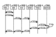
端末152から接続要求を送出し(図14内のステップG01)、メディアルータ153が受付確認する(ステップG02)。続いて、メディアルータ153は呼設定要求を終端ゲートウェイ145−2内の終端制御部154に送出し(ステップG04)、終端制御部154は、前記呼設定要求を受信すると共通線信号方式に基づく初期アドレスメッセージ(IAM)を形成して送出し(ステップG05)、中継ゲートウェイ145−3内の中継制御部155は、前記初期アドレスメッセージ(IAM)を移動網146において用いられる形式の初期アドレスメッセージ(IAM)に変えて送出し(ステップG06)、前記初期アドレスメッセージは中継ゲートウェイ146−2内の中継制御部156及び中継ゲートウェイ146−3内の終端制御部158を経由し、以下、一連の呼接続制御手順が遂行され(ステップG07乃至G49),端末152と端末160との間の通信路が確立される。端末152と端末160とが共に電話機であるケースでは、ステップG50−2においてディジタル化した電話音声の送受が行われる。端末152と端末160とが音声画像送受機能を有する端末のケースでは音声画像通信のための制御手順を実施し(ステップG50−1)、次に音声画像などのメディアを送受し(ステップG50−2)、音声画像通信の終了制御手順を実施する(ステップG50−3)。次に端末152が解放要求を出し(ステップG51)、以下一連の手順が実施され(ステップG52乃至G71)、前記端末間通信が終了する。また、特許文献2は前記と逆方向の接続要求、即ち端末160が発信側であり、端末152が着信側である共通線信号方式をベースとした端末間接続制御方法も開示している。
1.無線LAN及びIP網を経由した通信を行う第1実施例
無線LAN及びIP網を経由した通信を行う第1実施例を説明する。本実施例は、前提とするIP網の実施において、電話機952−1(図10)―無線基地局951−1―網ノード装置950−2、を経由する論理的な通信路において、無線基地局951−1を、無線部1203(図15)とメディアルータ1219とに置き換えて、LAN1200内部で無線インタフェースを有する電話機や端末を実施する形態に相当する。
A connection request is sent from the terminal 152 (step G01 in FIG. 14), and the
1. First Embodiment for Performing Communication via Wireless LAN and IP Network A first embodiment for performing communication via a wireless LAN and IP network will be described. In the present embodiment, in the implementation of the assumed IP network, the radio base station is in a logical communication path that passes through the telephone 952-1 (FIG. 10) —the radio base station 951-1—the network node device 950-2. 951-1 is replaced with a wireless unit 1203 (FIG. 15) and a
図15において、900はIP網(IP通信網)、901−1及び901−4は終端ゲートウェイ、906−1及び909−1は網ノード装置、906−4及び909−4は電話管理サーバ、906−5及び909−5は電話番号サーバ、903−4はメディアルータ、905−4は電話機、1230及び917−2は通信回線であり、以上列挙した項目は通信回線1230を除き、それぞれ図1により開示した機能と同一の符号であり、同一の名称及び機能を有する。電話管理サーバ906−5の外部IPアドレスは“EA81”である。1200は無線LANの範囲を示し、1201乃至1203は無線部、1204乃至1206は無線送受信部、1207乃至1209はIP処理部、1210乃至1212,1211xは無線通信路、1214乃至1216は通信回線、1217乃至1218はルータ、1219はメディアルータ、1220乃至1223はIPパケット送受信機能を有する端末(ただし、電話機の機能を含む端末)、1224は認証付電話番号サーバである。端末登録表1260は、無線LAN管理者により維持管理される。無線部1201乃至1203は、無線送受信部1204乃至1206をこの順に含み、同様にIP処理部1207乃至1209をこの順に含む。端末1220、ルータ1217、無線部1201は、通信回線1214を経由して互いにIPパケットを送受できる。端末1221及び1222、ルータ1218、無線部1202は、通信回線1215を経由して互いにIPパケットを送受できる。端末1223、メディアルータ1219、認証付電話番号サーバ1224、無線部1203は通信回線1216を経由して互いにIPパケットを送受できる。
In FIG. 15, 900 is an IP network (IP communication network), 901-1 and 901-4 are termination gateways, 906-1 and 909-1 are network node devices, 906-4 and 909-4 are telephone management servers, 906 -5 and 909-5 are telephone number servers, 903-4 is a media router, 905-4 is a telephone, 1230 and 917-2 are communication lines, and the items listed above are shown in FIG. 1 except for the
500(図15内)はIPパケット送受信機能を有する無線端末であり、無線通信機能及び電話機の機能を含む。無線端末500は無線通信機能モジュール1202x、及び電話機の機能を含むIPパケット送受信機能モジュール1222xを含む。
Reference numeral 500 (in FIG. 15) denotes a wireless terminal having an IP packet transmission / reception function, which includes a wireless communication function and a telephone function. The
1260(図16)は端末登録表を示しており、無線LANに含まれる端末の少なくとも電話番号及びIPアドレスを含む。また、端末が用いるポート番号や端末の電話利用状況(オン/オフ)、電話識別記号、メールアドレスを含むこともできる。例えば端末登録表1260の表題部を除いた第1行目のレコードは、“1,TN1,”E1”,5002,off,T1220,mm1@b1.cc.…,”となっており、第1行目のレコードの意味は、レコード番号は“1”、電話番号は“TN1”、IPアドレスは“E1”、ポート番号は“5002”、電話利用は“休止”、電話機識別番号は“T1220”、メールアドレスは“mm1@b1.cc.…,”となっている例である。 Reference numeral 1260 (FIG. 16) denotes a terminal registration table, which includes at least a telephone number and an IP address of a terminal included in the wireless LAN. It can also include a port number used by the terminal, a telephone usage status (on / off) of the terminal, a telephone identification symbol, and a mail address. For example, the record in the first line excluding the title part of the terminal registration table 1260 is “1, TN1,“ E1 ”, 5002, off, T1220, mm1@b1.cc.. The meaning of the record in the line is “1” for the record number, “TN1” for the telephone number, “E1” for the IP address, “5002” for the port number, “pause” for telephone use, and “T1220” for the telephone identification number. In this example, the email address is “mm1@b1.cc.
端末登録表1260はメディアルータ1219内部に設定してある(図15)。なお、他の実施例として、端末登録表1260は認証付電話管理サーバ1224(図15)の内部に設定しておくこともできる。メディアルータ1219は、ディジタル電話や画像などを扱えるように機能拡張したルータであり、メディアルータの内部構成は特許文献2などにおいて開示されている。
The terminal registration table 1260 is set in the media router 1219 (FIG. 15). As another embodiment, the terminal registration table 1260 can be set in the authenticated telephone management server 1224 (FIG. 15). The
次に図17を参照して説明する。無線MACフレーム1225は、少なくともMACヘッダ1227、IPパケット1226、MACトレイラ1228を含む。また、暗号初期値1229及び暗号判定値1230を含むことも可能である。MACヘッダ1227はMACアドレス等を含み、MACトレイラ1228は誤り訂正符号などを含み、暗号初期値1229はストリーム暗号技法における初期値であり、暗号判定値1230は例えばデータ完全性(暗号技術を用いた一種の誤り検出符号)を表わす判定データである。暗号機能を用いるとき、即ち暗号初期値1229及び暗号判定値1230を用いるとき、IPパケット1226の範囲は暗号文を格納する。IP処理部1208等は暗号鍵を含み、暗号化又は復号化の機能を含む。
Next, a description will be given with reference to FIG. The
図18及び図15を参照して、端末1222と端末1223との間でIPパケットを送受する例を説明する。ここで、端末1222のIPアドレスは“E1”、端末1223のIPアドレスは“E4”のケースである。端末1222はIPパケット1231を形成して通信回線1215(図15)へ送出する(ステップC01)。ただし、IPパケットのソースIPアドレスは“E1”、宛先IPアドレスは“E4”である。次に、IP処理部1208においてIPパケット1231が暗号文に変換され(ステップC02)、前記生成された暗号文、暗号初期値及び暗号判定値が添付されて無線送受信部1205に送られる(ステップC03)。このとき、IPパケット1231は暗号化されて暗号文IPパケット1241となっている。無線送受信部1205は無線通信用のMACフレーム1232を形成する(ステップC04)。次に、MACフレーム1232は無線通信路1211へ送出される(ステップC05)。無線送受信部1206はMACフレーム1232を受信して、MACフレーム1232から暗号文IPパケット1241を取り出し(ステップC06)、暗号文IPパケット1241及び暗号初期値及び暗号判定値をIP処理部1209へ送出する(ステップC07)。そして、IP処理部1209は、暗号文IPパケット1241を復号化して平文IPパケット1233を取得して(ステップC08)、通信回線1216へ送出し(ステップC09)、端末1223は前記復元したIPパケット1231を受信する。逆方向のIPパケット転送も前述同様に可能であり、端末1223が生成したIPパケット1234は、IP処理部1209、無線送受信部1206、無線通信路1211、無線送受信部1205、IP処理部1208を経由して端末1222に到達する(ステップC11乃至ステップC19)。なお、前記手順において暗号機能を用いないとき、MACフレーム1232内のIPパケット1241は平文である。
An example in which IP packets are transmitted and received between the terminal 1222 and the terminal 1223 will be described with reference to FIGS. Here, the IP address of the terminal 1222 is “E1”, and the IP address of the terminal 1223 is “E4”. Terminal 1222
次に、端末1222と端末1223との間でIPパケットを送受し、IP処理部1208及び1209においてIPパケットをIPカプセル化し、或いは逆カプセル化するケースを、図19を参照して説明する。このケースにおいて、IP処理部1208は、IPアドレス“J1”、IP処理部1209はIPアドレス“J2”を有する。端末1222はIPパケット1237を形成して送出し(ステップD01)、IP処理部1208はIPパケット1237を暗号文に変換する。続いて、IP処理部1208は前記生成された暗号文、暗号初期値及び暗号判定値をまとめてIPカプセル化を行い、内部IPパケット1244を形成する(ステップD02)。内部IPパケットのソースIPアドレスは“J1”、宛先IPアドレスは“J2”である。前記形成された内部IPパケット1244は無線送受信部1205に送られる(ステップD03)。無線送受信部1205は、内部IPパケット1244を含むMACフレーム1238を形成する(ステップD04)。次に、MACフレーム1238は無線通信路1211へ送出される(ステップD05)。無線送受信部1206はMACフレーム1238を受信して、MACフレーム1238内部から内部IPパケット1244を取り出し(ステップD06)、IP処理部1209へ送出する(ステップD07)。IP処理部1209は、内部IPパケット1244から暗号文となっているIPパケット1244を取り出し、IPパケット1244を復号化して平文のIPパケット1239に復号化し(ステップD08)、通信回線1216へ送出し(ステップD09)、端末1223はIPパケット1239を受信する。逆方向のIPパケット転送も前記同様に可能であり、端末1223が生成したIPパケット1240は、IP処理部1209、無線送受信部1206、無線通信路1211、無線送受信部1205、IP処理部1208を経由して端末1222に到達する(ステップD11乃至ステップD19)。
Next, a case where an IP packet is transmitted and received between the terminal 1222 and the terminal 1223 and the IP packet is IP-encapsulated or decapsulated in the
端末1221と端末1220との間で前記同様の手順により、また同様のMACフレームや暗号機能により、更にIPカプセル化と逆カプセル化を行い、IP処理部1208、無線送受信部1205、無線通信路1210、無線送受信部1204、IP処理部1207を経由してIPパケットを送受することができる。
IP encapsulation and decapsulation are further performed between the terminal 1221 and the terminal 1220 by the same procedure as described above, and by the same MAC frame and encryption function, and the
次に図20を参照して説明すると、無線LAN内の任意の端末から、例えば端末1222から認証機能付電話番号サーバ1224に電話番号を提示し(ステップ1271乃至1273)、前記電話番号を有する電話機乃至端末が用いるIPアドレスやポート番号を取得できる(ステップ1274乃至1276)。ここで、電話番号サーバに電話番号を含むIPパケットを提示し、IPアドレスやポート番号を取得する公知の技法を用いて実施できる。
<<無線LAN内部の端末からの発信>>
次に図21を参照して、電話機の機能を含む端末1222から電話機905−4に電話通信するための端末間通信接続制御方法を説明する。
Next, referring to FIG. 20, a telephone number is presented from an arbitrary terminal in the wireless LAN, for example, from the terminal 1222 to the telephone number server with authentication function 1224 (
<< Transmission from terminal inside wireless LAN >>
Next, a terminal-to-terminal communication connection control method for telephone communication from the terminal 1222 including the telephone function to the telephone 905-4 will be described with reference to FIG.
端末1222の電話番号は“TN1”、電話機905−4の電話番号は“TN2”であり、端末1222のIPアドレスは“E1”、電話機905−4にアクセスするためのメディアルータ903−4のIPアドレスは“E2”のケースである。本ケースにおいて、着信側となる電話機905−4側は、図2を用いて説明した着信側の通信接続制御手順とほぼ一致する。即ち、図2内のメディアルータ903−1とメディアルータ903−4との間の通信接続制御手順は、図21内のメディアルータ1219とメディアルータ903−4との間の通信接続制御手順とほぼ一致する(図2内に記載される網ノード装置906−1と網ノード装置903−4との間の手順が一部省略されて、図21内の網ノード装置906−1と網ノード装置903−4との間の手順として記載されている)。
The telephone number of the terminal 1222 is “TN1”, the telephone number of the telephone 905-4 is “TN2”, the IP address of the terminal 1222 is “E1”, and the IP of the media router 903-4 for accessing the telephone 905-4 The address is “E2”. In this case, the telephone 905-4 side serving as the incoming side substantially matches the communication connection control procedure on the incoming side described with reference to FIG. That is, the communication connection control procedure between the media router 903-1 and the media router 903-4 in FIG. 2 is almost the same as the communication connection control procedure between the
発呼側の端末1222とメディアルータ1219との間の通信は、図18乃至図20を参照して説明していることから、端末1222と電話機905−4との間の端末間通信接続制御手順が実施可能であり、次に説明する。
Since the communication between the calling terminal 1222 and the
端末1222が呼接続要求を含むIPパケットを送出すると、呼接続要求はメディアルータ1219に伝えられ(図21のステップM01、M3a,M3b,M3c,M3d)、メディアルータ1219はその内部の端末登録表1260(図16)を参照して、端末1222の電話番号“TN1”とIPアドレス“E1”とが端末登録表1260の表題部を除いた第1行目のレコードに登録されているかを確認し(ステップM3e)、メディアルータ1219は呼接続要求受付を返信する(ステップM4a,M4b,M4c,M4d,M02)。ここで、前記IPパケットは、送信元となる電話番号“TN1”及び宛先となる電話番号“TN2”を含む。IPパケットの送信元IPアドレスは“E1”、宛先IPアドレスは電話管理サーバ906−5のIPアドレス“EA81”である。なお、メディアルータ1219が端末登録表1260を含まず、その代わりに認証付電話番号サーバ1224(図15)が端末登録表1260を含む他のケースでは、メディアルータが認証付電話番号サーバ1224を呼出して端末登録表を取得し(図21のステップM3f)、前記取得した端末登録表1260を用いて、電話番号“TN1”とIPアドレス“E1”とが端末登録表1260に登録されているかを確認する。前記手順において、電話番号“TN1”とIPアドレス“E1”とが端末登録表に登録されていないケースでは、前記手順(ステップM4a乃至M02)において呼接続要求拒否を回答し、以降に示す接続制御手順を実施しない。
When the terminal 1222 sends an IP packet including a call connection request, the call connection request is transmitted to the media router 1219 (steps M01, M3a, M3b, M3c, and M3d in FIG. 21), and the
更に、前記手順において、端末1222が無線LAN1200内の認証付電話番号サーバ1224に問合わせ(図21のステップM00a)、IP網900にアクセスするための外部IPアドレスを取得し(ステップM00b)、次に端末1222から電話機905−4を呼び出す通信接続制御を行うこともできる。
Further, in the above procedure, the terminal 1222 inquires the authenticated
次に、メディアルータ1219が呼設定要求を含む前記IPパケットを送出すると(図21のステップM04)、呼設定要求を含むIPパケットは通信回線1230(図15)を経て網ノード装置906−1、電話管理サーバ906−4へ送信される(ステップM06)。電話管理サーバ906−4は、電話番号サーバ906−5に質間して回答を得る(ステップM07、M08)。次に、電話管理サーバ906−4は、呼設定要求を行うための初期アドレスメッセージとしてのIAMパケットを形成し、電話管理サーバ909−4へ送信する(ステップM21)。呼設定要求は網ノード装置909−1を経てメディアルータ903−4へ通知され(ステップM22、M24)、メディアルータ903−4は着信通知を電話機905−4へ通知する(ステップM25)。メディアルータ903−4は着信可能性を知らせるパケットを返信し、前記返信されたパケットは電話管理サーバ909−4へ通知され(ステップM31、M33)、前記返信されたパケットはアドレス完了メッセージ(ACMパケット)となって電話管理サーバ906−4へ通知され(ステップM34)、前記アドレス完了メッセージの内容はメディアルータ1219まで通知され(ステップM35,M37、オプション)、次に電話機905−4から端末1222へ呼出中通知が報告される(ステップM40乃至M48)。ただし、電話管理サーバ909−4から電話管理サーバ906−4の区間(ステップM44)は呼経過メッセージ(CPGパケット)が転送される。次に電話機905−4から端末1222へ応答通知が報告される(ステップM50乃至M58)。ただし、電話管理サーバ909−4から電話管理サーバ906−4の区間(ステップM54)は応答メッセージ(ANMパケット)が転送される。
Next, when the
次に電話管理サーバ906−4は、他の実施例で説明している表管理サーバに依頼し、網ノード装置906−1内にIPカプセル化等を規定する通信レコードを設定し(ステップM66)、同様に電話管理サーバ909−4は網ノード装置909−1内にIPカプセル化等を規定する通信レコードを設定する(ステップM64)。以上の手順により、端末1222と電話機905−4との間の音声通信路が確立した。 Next, the telephone management server 906-4 makes a request to the table management server described in another embodiment, and sets a communication record that specifies IP encapsulation or the like in the network node device 906-1 (step M66). Similarly, the telephone management server 909-4 sets a communication record defining IP encapsulation or the like in the network node device 909-1 (step M64). With the above procedure, the voice communication path between the terminal 1222 and the telephone set 905-4 was established.
端末1222と電話機905−4との間で、他の実施例で説明していると同じ方法により音声通信が行われる(ステップM68−1乃至M68−5及びステップM69−1乃至M69−5)。音声通信が終了すると音声通信路の解放手順が行われる(ステップM70乃至M79及びステップM80乃至M87)。ただし、電話管理サーバ906−4と電話管理サーバ909−4との区間(ステップM74)は解放要求メッセージ(RELパケット)が転送され、電話管理サーバ909−4と電話管理サーバ906−4との区間(ステップM84)は解放完了メッセージ(RLCパケット)が転送される。次に電話管理サーバ906−4は、表管理サーバに依頼して音声通信のために前記設定した通信レコードを抹消し(ステップM96)、同様に電話管理サーバ909−4は網ノード装置909−1内に設定した通信レコードを抹消する(ステップM98)。
<<無線LAN内部の端末の着信>>
次に、図22を参照して、無線LAN1200内部の端末1222が電話機905−4からの電話呼出しの受信(着信)を行う例を説明する。端末1222の電話番号は“TN1”、電話機905−4の電話番号は“TN2”であり、端末1222のIPアドレスは“E1”、電話機905−4にアクセスするためのメディアルータ903−4のIPアドレスは“E2”のケースである。本ケースにおいて、発呼側電話機905−4の側は、図2を用いて説明した発呼側の呼接続制御手順と一致する。即ち、図2内のメディアルータ903−1とメディアルータ903−4との間の通信接続制御手順は、図22内のメディアルータ903−4とメディアルータ1219との間の通信接続制御手順と一致する。
Voice communication is performed between the terminal 1222 and the telephone set 905-4 by the same method as described in other embodiments (steps M68-1 to M68-5 and steps M69-1 to M69-5). When the voice communication is completed, a voice communication path release procedure is performed (steps M70 to M79 and steps M80 to M87). However, the release request message (REL packet) is transferred in the section (step M74) between the telephone management server 906-4 and the telephone management server 909-4, and the section between the telephone management server 909-4 and the telephone management server 906-4. In (Step M84), a release completion message (RLC packet) is transferred. Next, the telephone management server 906-4 requests the table management server to delete the set communication record for voice communication (step M96). Similarly, the telephone management server 909-4 uses the network node device 909-1. The communication record set in is deleted (step M98).
<< Incoming call of terminal inside wireless LAN >>
Next, an example in which the
着信側の端末1222とメディアルータ1219との間の通信の範囲1200−3(図22)は、図19を参照して説明しているIPパケットをMACフレームに格納して送信し受信する手順を用いている。
The communication range 1200-3 (FIG. 22) between the terminal 1222 on the receiving side and the
メディアルータ1219は、認証付電話番号サーバ1224を呼出し、認証付電話番号サーバ1224が有する端末登録表を用いて、端末1222の電話番号“TN1”とIPアドレス“E1”とが端末登録表1260に登録されているかを確認する(図22のステップN24a)。
<<無線LAN−IP網−無線LAN間の通信>>
他の端末間通信接続制御方法を、図23及び図19を参照して説明する。900はIP網、1200は無線LANであり、図15において用いた符号及び機能と同一である。1200Rは無線LAN、1219Rはメディアルータ、1202R及び1203Rは無線部、1211Rは無線通信路、1222Rは電話機の機能を含む端末であり、無線LAN1200Rは、無線LAN1200の内部構成や機能と同様である。メディアルータ1219Rは、無線LAN1200R内の端末を登録するための端末登録表1260(図21)と同じ形式の端末登録表を含む。
The
<< Communication between wireless LAN-IP network and wireless LAN >>
Another terminal-to-terminal communication connection control method will be described with reference to FIGS.
前記説明したように、無線LAN1200内の端末1222が発信する端末間通信接続手順が可能であり(図21)、無線LAN1200内の端末1222が着信する端末間通信接続手順が可能であることから(図22)、図23に示すように端末1222、メディアルータ1219、IP網900、メディアルータ1219R、端末1222Rを結ぶ端末間通信が可能であり、端末1222から端末1222RにIPパケットを送信し(図24のステップ1280乃至1284)、逆方向にも送信できる(ステップ1285乃至1289)。
<<無線LAN内で用いる無線端末>>
無線端末500(図25)はIPパケット送受信機能を有する端末であり、無線通信機能及び電話機の機能を含む。無線端末500内の無線通信機能モジュール1202x(図15)は無線部1202が有する無線通信機能を含み、更にIPパケット送受信機能モジュール1222x(図15)は、端末1222が有するIPパケット送受信機能及び電話機の機能を含む。このようになっているから、無線端末500は無線LAN内で用いる移動電話機として用いることができる。更に、無線端末500はIPパケットを送受してディジタルデータを送受できる端末として、また、ディジタル化した画像や音声を送受可能な移動電話機、無線機能付音声画像装置として用いることもできる。
As described above, the inter-terminal communication connection procedure that the terminal 1222 in the
<< Wireless terminal used in wireless LAN >>
The wireless terminal 500 (FIG. 25) is a terminal having an IP packet transmission / reception function, and includes a wireless communication function and a telephone function. The wireless
更に、無線端末500は、無線通信路1211x、無線部1203、メディアルータ1219、通信路1230、IP網900、メディアルータ903−4を経由して固定電話機905−4と電話通信可能であり、更に同様にして、無線端末500は、無線通信路1211x、無線部1203、メディアルータ1219、通信路1230、IP網900、無線基地局902−4を経由して移動電話機905−8と電話通信可能である。同様に、無線端末500は、無線通信路1211x、無線部1203、メディアルータ1219、通信路1230、IP網900、メディアルータ903−4を経由してIP端末905−17とIPパケットを送受する通信が可能である。更に、無線端末500は、無線通信路1211x、無線部1203、無線通信路1212(図15)、無線部1201を経由して、端末1220と電話通信し、乃至、ディジタル化した画像や音声・画像を送受する通信が可能である。
Further, the
無線端末500と、固定電話機905−4や移動電話機505−8、IP端末905−17との間の電話呼接続制御を実施するために、IP網900内部の通信回線には共通線信号方式に従う電話呼接続制御メッセージが送受される。なお、共通線信号方式に関しては、例えば端末1222と電話機905−4との間の電話通信(図21及び図22)と同じ原理である。
<<無線端末を通信網に接続する方法>>
無線端末500を無線LAN1200の内部で用いず、他の通信網に接続する方法を説明する。500、500−1、500−2、500−3(図25)は同一の無線端末であり、異なる点は無線通信路を経由する接続先の違いである。無線端末500は、無線通信路1211xを経て無線部1203に接続しており、無線端末500−1は、無線通信路1231を経てIP網900の無線基地局902−5に接続しており、無線端末500−2は、無線通信路1232を経てIP網900の無線基地局902−3に接続している。更に、無線端末500−3は、無線通信路517を経て移動通信網510の無線基地局513に接続している。
In order to perform telephone call connection control between the
<< Method for Connecting Wireless Terminal to Communication Network >>
A method of connecting the
無線端末500−1は無線基地局902−5と通信を行う無線通信機能を有しているので、無線端末500−1−無線基地局902−5−IP網900内部−無線基地局902−4−移動電話機905−8を経由して移動電話機905−8と電話通信可能である。更に、無線端末500−1は、無線端末500−1−無線基地局902−5−IP網900内部−メディアルータ903−4−固定電話機905−4を経由して固定電話機905−4と電話通信可能である。更に、無線端末500−1は、無線端末500−1―無線基地局902−5―IP網900内部−メディアルータ903−4―IP端末905−17を経由して、共通線信号方式によりIP端末905−17間の通信路を確立し、次に無線端末500−1と端末905−17とは、IPパケットを送受してディジタルデータを送受したり、ディジタル化した画像や音声を送受することが可能である。同様にして、端末500−2と移動電話905−8との間でIP網900を経て通信可能であり、また、端末500−2と固定電話機905−4との間でIP網900を経て通信可能であり、更に端末500−2とIP端末905−17との間で、IP網900を経て通信可能である。
Since the wireless terminal 500-1 has a wireless communication function for communicating with the wireless base station 902-5, the wireless terminal 500-1-wireless base station 902-5—inside the
510(図25)はIP網900とは異なる移動通信網である。移動電話機505と移動電話機506とは、移動電話機505―無線基地局513―交換機511―通信回線515―交換機512―無線基地局514−移動電話機506を経由して電話通信可能である。通信回線515には、共通線信号方式に従う電話呼接続制御メッセージが送受されて、移動電話機505と移動電話機506との間の電話通信のための電話呼接続制御が実施される。
510 (FIG. 25) is a mobile communication network different from the
無線端末500−3は無線基地局513との無線通信機能を有しているので、無線端末500−3―無線基地局513―交換機511―移動網510内部の通信回線−交換機512−無線基地局514―移動電話機506を経由して、移動電話機506と通信が可能である。移動電話機506が、ディジタル音声や画像データIPパケットに格納して送受可能であれば、無線端末500−3と移動電話機506とは、IPパケットを送受し、ディジタル化した画像や音声を送受することもできる。移動電話機506の代わりに無線機能を有し、ディジタルデータや音声、画像を送受できる端末(無線機能付音声画像端末)を用い、無線端末500−3と無線機能付音声画像端末との間で移動通信網510を経由して通信することもできる。
<<無線LAN―IP網―PSTN又は移動通信網経由の通信>>
図26は、無線LAN―IP網―公衆交換電話網(PSTN)を経由する通信、及び無線LAN―IP網―移動通信網を経由する通信を説明する図である。600はIP網、601は移動通信網、602が公衆交換電話網、1200は無線LAN、603は終端ゲートウェイ、604及び605は中継ゲートウェイ、606は中継交換機、607は終端交換機、608は移動通信網の中継交換機(関門移動網加入者制御局ともいう)、609は移動通信網の交換機(移動網加入者制御局ともいう)、610は無線基地局、612は公衆交換電話網602の端末、613は移動通信網601の端末である。
Since the wireless terminal 500-3 has a wireless communication function with the
<< Wireless LAN-IP network-PSTN or communication via mobile communication network >>
FIG. 26 is a diagram for explaining communication via a wireless LAN-IP network-public switched telephone network (PSTN) and communication via a wireless LAN-IP network-mobile communication network. 600 is an IP network, 601 is a mobile communication network, 602 is a public switched telephone network, 1200 is a wireless LAN, 603 is a termination gateway, 604 and 605 are relay gateways, 606 is a relay switch, 607 is a termination switch, and 608 is a
図27は無線端末500から、無線通信路1211x、メディアルータ1219を経由し、終端ゲートウェイ603、IP網600の内部、中継ゲートウェイ604、中継交換機606、公衆交換電話網602の内部、終端交換機607を経由して、端末612への端末間通信接続制御方法を示している。通信手順範囲1200−5(図27)及び、通信手順範囲600−5は、例えば通信手順範囲1200−2(図21)及び通信手順範囲900−2と同様に、無線LAN内部の端末からIP網へ向かう共通線信号方式に基づく通信接続制御を実施している。通信手順範囲602−5(図27)は公知の技法である。ステップ631X乃至658Xは端末間通信の通信路確立フェーズであり、ステップ660Xにおいて、音声や画像などが端末間で送受される。ステップ664X乃至678Xは端末間通信の通信路解放フェーズである。通信手順範囲600−5内や602−5内のステップ634X,636Xなどにおいて、共通線信号方式による通信接続制御が遂行される。
In FIG. 27, from the
図28は前記と逆方向に、即ち端末612から公衆交換電話網602、IP網600、無線端末500への端末間通信接続制御方法を示している。通信手順範囲1200−6(図28)及び600−6は、例えば通信手順範囲1200−3(図22)及び900−3と同様に、IP網から無線LAN内部の端末へ向かう共通線信号方式に基づく通信接続制御を実施している。通信手順範囲602−6(図27)は公知の技法である。図28内の端末間通信接続制御のステップは、図27のステップ名の末尾の“X”を“Y”にして表現したステップと同様である。
FIG. 28 shows a terminal-to-terminal communication connection control method from the terminal 612 to the public switched
要約すると、無線端末―無線LAN−IP網―公衆交換電話網−端末を結ぶ通信路を経て、前記無線端末と公衆交換電話網に接続する前記端末間の通信を実施可能であり、IP網及び公衆交換電話網内部は共通線信号方式に基づく接続制御を行う。 In summary, communication between the wireless terminal and the terminal connected to the public switched telephone network can be performed via a communication path connecting the wireless terminal, the wireless LAN, the IP network, the public switched telephone network, and the terminal. The inside of the public switched telephone network performs connection control based on the common line signal system.
図29は、無線端末500から無線通信路1211x、メディアルータ1219を経由し、終端ゲートウェイ603、IP網600の内部、中継ゲートウェイ605、中継交換機608、交換機609、無線基地局610を経由して端末613への端末間通信接続制御方法を示している。通信手順範囲1200−7(図29)及び600−7は、例えば通信手順範囲1200−5(図27)及び600−5と同様である。通信手順範囲601−7(図29)は145−1(図14)と同様である。
FIG. 29 shows the terminal from the
図30は前記と逆方向に、即ち端末613から移動通信網601、IP網600、無線端末500への端末間通信接続制御方法を示している。通信手順範囲1200−8(図30)及び600−8は、例えば通信手順範囲1200−6(図28)及び600−6と同様であり、通信手順範囲602−5(図30)は、例えば特許文献2(図14)などに開示され端末間通信接続制御と同様である。図29及び図30内の端末間通信接続制御のステップは、図27及び図28に示すステップと同様である。要約すると、無線端末―無線LAN−IP網―移動通信網−端末を結ぶ通信路を経て、無線端末と端末間の通信を実施可能であり、IP網及び移動通信網内部は共通線信号方式に基づく接続制御を行う。
<<まとめ>>
無線LANに接続する端末がIP網を経由して他の端末と通信できるようにするため、IP網内に認証サーバを設置し、無線LAN内部の端末に対する認証手続きを遂行する。
FIG. 30 shows a terminal-to-terminal communication connection control method from the terminal 613 to the
<< Summary >>
In order to enable a terminal connected to the wireless LAN to communicate with another terminal via the IP network, an authentication server is installed in the IP network and an authentication procedure for the terminal inside the wireless LAN is performed.
IP網は2以上の網ノード装置を含み、外部IPパケットが入側網ノード装置において内部パケットに変換されてIP網内部を転送され、出側網ノード装置において内部パケットから外部IPパケットが復元されるようになっており、無線LANは、前記無線LAN内のメディアルータ1から、通信回線を経て前記IP網の網ノード装置の1つに接続されており、無線LANは端末1を含み、端末2はメディアルータ2を経由してIP網の網ノード装置の1つに通信回線を経て接続されており、端末登録表はメディアルータ1の内部に設定されており、端末1から端末2に接続するときは、端末1が端末登録表の管理の基に発信許可を得る手順を含む通信接続制御を行うようになっており、端末2から端末1に接続するときは、端末1が端末登録表の管理の基に着信許可を得る手順を含む通信接続制御を行うことも可能であり、端末登録表の管理の基に端末1と端末2とが無線LANとIP網を経由して通信することができる。
The IP network includes two or more network node devices. The external IP packet is converted into an internal packet at the ingress network node device and transferred inside the IP network, and the external IP packet is restored from the internal packet at the egress network node device. The wireless LAN is connected to one of the network node devices of the IP network via a communication line from the
また、端末登録表はメディアルータ1の内部に含まれず、認証付電話番号サーバ内部に含まれており、メディアルータ1が認証付電話番号サーバを呼び出して端末登録表を用いるようにすることもできる。
Further, the terminal registration table is not included in the
無線LAN内で送受される無線MACフレームは、IPカプセル化されている内部パケットを含むことが可能である。端末1が無線LAN1内の認証付電話番号サーバに問合わせてIP網にアクセスするための外部IPアドレスを取得し、次に端末1から端末2を呼び出す通信接続制御を行うこともできる。端末1と端末2とが、無線LANとIP網を経由する通信端末間通信に用いるIP網は、図1により開示しているIP網900、即ち固定電話、移動電話、マルチメディア通信のいずれも実施できるIP網を用いることもできる。
The wireless MAC frame transmitted / received within the wireless LAN can include an internal packet that is IP-encapsulated. It is also possible to perform communication connection control in which the
端末1と端末2との間の他の端末間通信接続制御方法として、無線LAN1は少なくとも端末1を含み、無線LAN2は少なくとも端末2を含み、無線LAN1は無線LAN1内のメディアルータ1、通信回線を経てIP網の1つの網ノード装置に接続されており、無線LAN2は無線LAN2内のメディアルータ2、通信回線を経てIP網の1つの網ノード装置に接続されており、端末登録表1はメディアルータ1の内部に設定されており、端末登録表2はメディアルータ1の内部に設定されており、端末1と端末2とが無線LAN1、IP網、無線LAN2を経由して通信することも可能である。
As another inter-terminal communication connection control method between the terminal 1 and the
無線LAN内で用いる無線端末500は移動電話機であり、更に無線通信機能を有し、IPパケット送受機能を有するIP端末でもある。無線端末は無線通信路を経て無線LANの無線部に接続し、更にメディアルータを経由してIP網に接続し、IP網に接続する電話機(固定電話機や移動電話機)やIPパケット送受機能を有するIP端末と通信できる。無線端末は、ディジタル化した画像や音声を送受可能な移動電話機や無線機能付音声画像装置として用いることもできる。また、無線端末は、無線通信路、無線基地局を経てIP網に接続して、IP網に接続する電話機(固定電話機や移動電話機)やIPパケット送受機能を有するIP端末と通信できる。また、無線端末は、無線通信路、無線基地局を経て移動通信網に接続して、移動通信網に接続する電話機(固定電話機や移動電話機)やIPパケット送受機能を有するIP端末と通信できる。無線端末と端末との間の通信を行うため、IP網及び移動通信網内部は共通線信号方式に基づく接続制御を行うことを特徴とする。
The
端末1と端末2とが、無線LAN1、IP網、無線LAN2を経由する通信端末間通信に用いるIP網は図1により開示しているIP網900、即ち固定電話、移動電話、マルチメディア通信のいずれも実施できるIP網を用いていることが特徴である。
2.無線基地局を切替えて電話通信を継続する第2実施例
図31は、IP網900(図1)内部の無線基地局902−1乃至902−5をその外部に取り出した形態であるIP網900Xを示しており、無線基地局902−2及び902−3はIP通信回線で終端ゲートウェイ901−3に接続し、無線基地局902−5はIP通信回線で終端ゲートウェイ901−1に接続し、無線基地局902−4はIP通信回線で終端ゲートウェイ901−4に接続している。202乃至205は無線通信領域であり、それぞれ無線基地局902−2乃至902−5と移動電話機との間で無線通信可能な範囲を示している。終端ゲートウェイ901−1乃至901−4(図1内)は、電話管理サーバその他各種のサーバを含む。各終端ゲートウェイは1以上の代理移動電話サーバを含むことが可能であるが、本実施例は代理移動電話サーバの数が1の例である。IP網900Xは、その外部の無線基地局と連携してIP網900と同等の機能を実施でき、また、IP網900X内リソース(網ノード装置、サーバ、通信回線など)は、IP網900と同一である。IP網900Xと無線基地局とを連携した通信機能と、IP網900の機能機能との本質的な違いはない。以降、IP網900とIP網900Xとを区別せずに説明する。
The IP network used by the
2. FIG. 31 shows an
移動電話機専用の電話番号サーバ966(図31)は、1以上のレコードで成る移動電話機登録表210を含む。移動電話機登録表210(図36)の表題部を除いた第1行目のレコードは、電話番号“TN3”を用いる電話通信用に用いる内部IPアドレス“IA301”及び外部IPアドレス“EA301”、無線基地局902−3へのUNIである“UNI3”、パスワード“PID3”を含み、他の行も同様である。 The telephone number server 966 (FIG. 31) dedicated to the mobile telephone includes a mobile telephone registration table 210 composed of one or more records. The record on the first line excluding the title part of the mobile telephone registration table 210 (FIG. 36) includes an internal IP address “IA301” and an external IP address “EA301” used for telephone communication using the telephone number “TN3”, wireless It includes “UNI3”, which is a UNI to the base station 902-3, and a password “PID3”, and the same applies to other lines.
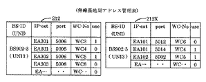
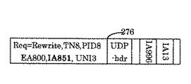
電話管理サーバ908−4が管理する終端ゲートウェイアドレス管理表211(図31、図37)は、ディジタル音声を格納したIPパケットをカプセル化するための内部IPアドレス“IA851”を内部IPアドレスの値が“IA43”である代理電話サーバを通過させることを指定している。なお、終端ゲートウェイアドレス管理表211内の内部IPアドレス“IA301、IA4、IA6、IA9”は、代理電話サーバと対応付けが未定であることを表わしている。他の電話管理サーバ906−4(図31)、907−4,909−4も、終端ゲートウェイアドレス管理表をそれぞれ管理している。 In the termination gateway address management table 211 (FIGS. 31 and 37) managed by the telephone management server 908-4, the internal IP address “IA851” for encapsulating the IP packet storing the digital voice is the internal IP address value. It is specified that the proxy telephone server “IA43” is allowed to pass. The internal IP addresses “IA301, IA4, IA6, IA9” in the termination gateway address management table 211 indicate that the association with the proxy telephone server is undecided. Other telephone management servers 906-4 (FIG. 31), 907-4, and 909-4 also manage the termination gateway address management table.
無線基地局902−3が管理している無線基地局アドレス管理表212(図39内)は、無線基地局902−3から通信回線経由で終端ゲートウェイに送信されるIPパケットのソースIPアドレス(若しくは発信アドレス)及びソースポート番号(若しくは発信ポート番号)と、無線基地局902−3から無線回線経由で移動電話機と通信するための無線回線識別記号とを含む。無線基地局アドレス管理表212の表題部を除いた第1行目はソースIPアドレス“EA301”、ソースポート番号“5006”、無線回線識別記号“WC3”であり、かつ第1行目が使用中であることを示している。第2行目はソースIPアドレス“EA301”、ソースポート番号“5008”、無線回線識別記号“WC4”であり、かつ第2行目が未使用であることを示している。無線基地局902−3は、電話呼要求発生に応じて、通信リソース、即ち、ソースIPアドレス、ソースポート番号、無線回線の配分管理を行い、配分管理の結果として無線基地局アドレス管理表212の書換えを行う。他の無線基地局902−1乃至902−5も、同様の無線基地局アドレス管理表を管理している。 The radio base station address management table 212 (in FIG. 39) managed by the radio base station 902-3 is a source IP address (or an IP packet) transmitted from the radio base station 902-3 to the termination gateway via the communication line. A transmission address) and a source port number (or a transmission port number) and a radio channel identification symbol for communicating with the mobile telephone from the radio base station 902-3 via the radio channel. The first line excluding the title part of the radio base station address management table 212 is the source IP address “EA301”, the source port number “5006”, the radio channel identification symbol “WC3”, and the first line is in use. It is shown that. The second line shows the source IP address “EA301”, the source port number “5008”, the wireless line identification symbol “WC4”, and the second line shows that it is unused. The radio base station 902-3 performs allocation management of communication resources, that is, a source IP address, a source port number, and a radio line in response to the occurrence of a telephone call request, and as a result of the allocation management, the radio base station 902-3 Rewrite. The other radio base stations 902-1 to 902-5 also manage the same radio base station address management table.
本実施例において、無線通信領域203内にある移動電話機905−6(図31)と移動電話機905−8とは、移動電話機905−6、無線基地局902−3、終端ゲートウェイ901−3、IP網900X内部、終端ゲートウェイ901−4、無線基地局902−4、移動電話機905−8を経由して電話通信を実施し、次の段階として、移動電話機905−6が、905−6Zの位置を経て、905−6yの位置に移動して電話通信を継続すること、即ち、移動電話機905−6y、無線基地局902−5、終端ゲートウェイ901−1、IP網900X内部、終端ゲートウェイ901−4、無線基地局902−4、移動電話機905−6を経由する電話通信として継続することを本実施例により説明する。
In this embodiment, the mobile telephone 905-6 (FIG. 31) and the mobile telephone 905-8 in the
以下の説明において、移動電話機905−6(図31)、移動電話機905−6z及び移動電話機905−6yは同一の電話機であるが、その所在位置が時間進行と共に異なっており、905−6は無線通信領域203内に位置している移動電話機であり、905−6zは無線通信領域203及び無線通信領域205が重なる場所に位置している移動電話機であり、905−6yは無線通信領域205内に位置している移動電話機を表わしている。
<<内部IPアドレスの配送>>
次に、図32及び図33を参照して、内部IPアドレスの配送方法を説明する。電話通信サービスの開始前において、運用管理サーバ915(図1、図33)は電話管理サーバ908−4に内部IPアドレスを配送し(ステップK1)、電話管理サーバ908−4は、終端ゲートウェイアドレス管理表211(図37)に、受信した内部IPアドレス“IA851,IA301,IA5,IA6,IA9”を書き込んで保持する。同様に、運用管理サーバ915は内部IPアドレスを配送し(ステップK4)、電話管理サーバ906−4は、受信した内部IPアドレスをその内部の終端ゲートウェイアドレス管理表211X(図64内)に保持する。更に、運用管理サーバ915は内部IPアドレスを配送し(ステップK7)、電話管理サーバ909−4は受信した内部IPアドレスをその内部の終端ゲートウェイアドレス管理表に保持する。なお、終端ゲートウェイアドレス管理表211(図37内)の内部アドレス“IA851”は、内部IPアドレス値が“IA43”である代理移動電話サーバと無線基地局とが、ユーザネットワークインタフェース“UNI3”により通信するために、内部アドレス“IA850”割り当てられているケースを示している。
<<主なIPアドレス>>
EA1は無線基地局902−5の外部IPアドレス、IA1は無線基地局902−5に接続する通信回線終端の論理端子の内部IPアドレス、EA3は無線基地局902−3の外部IPアドレス、IA3は無線基地局902−3に接続する通信回線終端の論理端子の内部IPアドレス、EA4は無線基地局902−4の外部IPアドレス、IA4は無線基地局902−4に接続する通信回線終端の論理端子の内部IPアドレスである。EMBは代理移動電話サーバに共通の外部IPアドレスであり、IA41は代理移動電話サーバ906−6の内部IPアドレス、IA42は代理移動電話サーバ907−6の内部IPアドレス、IA43は代理移動電話サーバ908−6の内部IPアドレス、IA44は代理移動電話サーバ909−6の内部IPアドレスである。
In the following description, the mobile phone 905-6 (FIG. 31), the mobile phone 905-6z, and the mobile phone 905-6y are the same phone, but their location differs with time, and 905-6 is wireless. 905-6z is a mobile phone located in a place where the
<< Internal IP address delivery >>
Next, the internal IP address delivery method will be described with reference to FIG. 32 and FIG. Before the start of the telephone communication service, the operation management server 915 (FIGS. 1 and 33) delivers the internal IP address to the telephone management server 908-4 (step K1), and the telephone management server 908-4 manages the termination gateway address. In table 211 (FIG. 37), the received internal IP address “IA851, IA301, IA5, IA6, IA9” is written and held. Similarly, the
<< Main IP addresses >>
EA1 is the external IP address of the radio base station 902-5, IA1 is the internal IP address of the logical terminal of the communication line connected to the radio base station 902-5, EA3 is the external IP address of the radio base station 902-3, and IA3 is The internal IP address of the logical terminal of the communication line connected to the wireless base station 902-3, EA4 is the external IP address of the wireless base station 902-4, and IA4 is the logical terminal of the communication line terminal connected to the wireless base station 902-4 Internal IP address. EMB is an external IP address common to the proxy mobile phone server, IA41 is the internal IP address of the proxy mobile phone server 906-6, IA42 is the internal IP address of the proxy mobile phone server 907-6, and IA43 is the proxy
IA11は電話管理サーバ906−4の(内部)IPアドレスであり、IA12は電話管理サーバ907−4の(内部)IPアドレスであり、IA13は電話管理サーバ908−4の(内部)IPアドレスであり、IA14は電話管理サーバ909−4の(内部)IPアドレスである。IA996は電話番号サーバ996の(内部)IPアドレスである。なお、電話管理サーバや電話番号サーバは外部IPアドレスを有しない。
IA11 is the (internal) IP address of the telephone management server 906-4, IA12 is the (internal) IP address of the telephone management server 907-4, and IA13 is the (internal) IP address of the telephone management server 908-4 IA14 is the (internal) IP address of the telephone management server 909-4.
EA301,EA401,EA101はディジタル音声送受などの通信フェーズにおいて用いる外部IPアドレスであり、IA301,IA401,IA101はディジタル音声送受などの通信フェーズにおいて用いる内部IPアドレスであり、ポート番号の“5006”は無線基地局902−3側がディジタル音声を送信するときに用いるソースポート番号であり、ポート番号の“5008”は無線基地局902−4側がディジタル音声を送信するときに用いるソースポート番号であり、ポート番号の“5012”は無線基地局902−5側がディジタル音声を送信するときに用いるソースポート番号である。ポート番号の“5060”は、端末間の電話呼接続制御手順(SIPなど)に適用可能なポート番号の数値例である。なお、IPパケット内のIPアドレスは先頭側からソースIPアドレス(送信元IPアドレス)、宛先IPアドレスの順序により図示しており、例えばIPパケット213(図40)内“EA3”はソースIPアドレスを意味し、“EMB”は宛先IPアドレスを意味する。IP網900内は、例えば前記IPアドレスのうち内部IPアドレスが付与されたIPパケットが送受される。
<<移動電話機の初期位置登録>>
移動電話機をIP網900に登録する手順を実施するが、これについては本実施例の後半部において説明する。
<<呼接続制御>>
図32及び図33を参照して、電話番号“TN3”である移動電話機905−6から電話番号“TN4”である移動電話機905−8を呼出す呼接続制御の前半部(即ち、ステップB01〜ステップB60−4)を説明する。前記呼接続制御の流れは、本発明の前提とするIP網(特許文献2の実施例8)の呼接続制御に示す移動電話機905−6から移動電話機905−8を呼出す呼制御の流れ(図5)の内、ステップB01〜ステップB60−4までとほぼ同一であるが、電話呼を管理するためのCIC管理表の表現形式、IPアドレスやポート番号の取得方法、サーバ類のアドレス値は本実施例において変更している。また、電話番号サーバとして、移動電話機専用の電話番号サーバ996(図31、図33)を用いている。
EA301, EA401, EA101 are external IP addresses used in the communication phase such as digital voice transmission / reception, IA301, IA401, IA101 are internal IP addresses used in the communication phase such as digital voice transmission / reception, and the port number “5006” is wireless. The source port number used when the base station 902-3 transmits digital voice, and the port number "5008" is the source port number used when the radio base station 902-4 transmits digital voice. “5012” is a source port number used when the radio base station 902-5 transmits digital voice. The port number “5060” is a numerical example of a port number applicable to a telephone call connection control procedure (SIP or the like) between terminals. Note that the IP address in the IP packet is illustrated in the order of the source IP address (source IP address) and the destination IP address from the head side. For example, “EA3” in the IP packet 213 (FIG. 40) indicates the source IP address. “EMB” means a destination IP address. In the
<< Initial location registration of mobile phone >>
A procedure for registering the mobile telephone in the
<< Call connection control >>
32 and 33, the first half of the call connection control for calling the mobile telephone 905-8 having the telephone number "TN4" from the mobile telephone 905-6 having the telephone number "TN3" (ie, step B01 to step B01). B60-4) will be described. The call connection control flow is a call control flow for calling the mobile telephone 905-8 from the mobile telephone 905-6 shown in the call connection control of the IP network (
電話機905−6から呼接続要求を送出すると(ステップB01)、無線基地局902−3が返信する(ステップB02)。次に、電話機905−6から送信元の電話番号“TN3”、宛先の電話番号“TN4”を含む呼設定要求を無線基地局902−3へ送出し(ステップB03)、無線基地局902−3は無線基地局アドレス管理表212(図39)を用いて、音声通信用の外部IPアドレス“EA301”及びポート番号“5006”、UNIの“UNI3”及び無線回線識別記号“WC3”を取得し、外部IPアドレス“EA301”及びポート番号“5006”及び付加情報“Info3”を含む呼設定要求用のIPパケット213(図40)を形成し、網ノード装置908−1へ送信する(ステップB04)。前記付加情報“Info3”として、少なくとも通信回線917−3(図31)のUNIの“UNI3”及び無線回線識別記号“WC3”とが含まれる。 When a call connection request is transmitted from the telephone set 905-6 (step B01), the radio base station 902-3 returns (step B02). Next, the telephone set 905-6 sends a call setting request including the transmission source telephone number “TN3” and the destination telephone number “TN4” to the wireless base station 902-3 (step B03), and the wireless base station 902-3. Uses the radio base station address management table 212 (FIG. 39) to obtain the external IP address “EA301” and port number “5006” for voice communication, the UNI “UNI3”, and the radio channel identification symbol “WC3”. A call setup request IP packet 213 (FIG. 40) including the external IP address “EA301”, port number “5006” and additional information “Info3” is formed and transmitted to the network node device 908-1 (step B04). The additional information “Info3” includes at least the UNI “UNI3” and the radio channel identification symbol “WC3” of the communication line 917-3 (FIG. 31).
網ノード装置908−1は装置制御表910−3(図52)内の第1行目のレコ−ド“IA3,IA43,Kzero,EMB,Mzero,M255,・・”を適用し、IPパケット213をカプセル化して内部パケット214(図41)を形成し、代理移動電話サーバ908−6へ送信する(ステップB05)。代理移動電話サーバ908−6はIPパケット214を基にIPパケット215(図42)を形成し、電話管理サーバ908−4へ送信する(ステップB06)。
The network node device 908-1 applies the record “IA3, IA43, Kzero, EMB, Mzero, M255,...” In the first row in the device control table 910-3 (FIG. 52), and the
次に、電話管理サーバ908−4は電話番号“TN3”及び電話番号“TN4”の組から回線番号“CIC-7”を算出し、CIC管理表908−4A(図55)を形成する。ここで、IPパケット215から、各種アドレスや関連情報(IA3,EA3, IA43, EMB, IA13,TN3, TN4, EA301,5006, UNI3,WC3)を取得している。また、項目“IAM”及び時刻“St3”を設定している。更に、電話管理サーバ908−4は、電話番号“TN3”及び “TN4”を含むIPパケット216(図43)を移動電話機専用の電話番号サーバ996に送出し(ステップB07x)、電話番号サーバ996は、その内部の移動電話機登録表210(図36)を用いて、電話番号“TN3”及び“TN4”に対応する各種IPアドレス、UNI,PIDを含むIPパケット217(図44)を回答する(ステップB08x)。
<<音声通信用のアドレスの比較と更新>>
電話管理サーバ908−4は、IPパケット217(図44)内部に、無線基地局902−3が送信するディジタル音声パケットをカプセル化するための内部IPアドレス(本ケースでは“IA301”)が存在するか(例えば無線基地局が開局した直後)、或は当該内部IPアドレス“IA301”が終端ゲートウェイアドレス管理表211(図37内)の内で割当て済み項目として含まれていないかを調べる。本ケースでは未割り当て領域に区分されているので、内部IPアドレス“IA301”を割り当て項目に変更する。このために、電話管理サーバ908−4は、終端ゲートウェイアドレス管理表211を終端ゲートウェイアドレス管理表211Z(図37内)として書き換える。なお、終端ゲートウェイアドレス管理表211内の未割り当てIPアドレスとして“IA301”が含まれていないケースでは、他のIPアドレス、例えば“IA5”を終端ゲートウェイアドレス管理表211Zのアドレス割り当て領域に移行する。
Next, the telephone management server 908-4 calculates the line number “CIC-7” from the set of the telephone number “TN3” and the telephone number “TN4”, and forms the CIC management table 908-4A (FIG. 55). Here, various addresses and related information (IA3, EA3, IA43, EMB, IA13, TN3, TN4, EA301, 5006, UNI3, WC3) are acquired from the
<< Comparison and update of address for voice communication >>
The telephone management server 908-4 has an internal IP address (in this case, “IA301”) for encapsulating the digital voice packet transmitted by the radio base station 902-3 in the IP packet 217 (FIG. 44). (For example, immediately after the radio base station opens) or whether the internal IP address “IA301” is included as an assigned item in the termination gateway address management table 211 (in FIG. 37). In this case, since it is divided into unallocated areas, the internal IP address “IA301” is changed to an allocated item. For this purpose, the telephone management server 908-4 rewrites the termination gateway address management table 211 as the termination gateway address management table 211Z (in FIG. 37). In the case where “IA301” is not included as an unassigned IP address in the termination gateway address management table 211, another IP address, for example, “IA5” is transferred to the address allocation area of the termination gateway address management table 211Z.
次に、電話管理サーバ908−4は、IPパケット217(図44)から取得したディジタル音声パケット用の外部IPアドレス(本ケースではEA301)と、IPパケット215(図42)から取得したディジタル音声パケット用の外部IPアドレス(本ケースではEA301)との値が一致するかを調べ、更にIPパケット217とから取得したディジタル音声パケット用の内部IPアドレス(本ケースではEA301)と、終端ゲートウェイアドレス管理表211Zから前記手順により取得したIPアドレス(本ケースではIA301)との値が一致しているかを調べる。
Next, the telephone management server 908-4 determines the external IP address (EA301 in this case) for the digital voice packet acquired from the IP packet 217 (FIG. 44) and the digital voice packet acquired from the IP packet 215 (FIG. 42). It is checked whether the value matches the external IP address (EA301 in this case) for the
本ケースでは、外部IPアドレス(EA301)及び内部IPアドレス(IA301)の値が共に一致するので次に進む。なお、前記外部IPアドレス又は内部IPアドレスの少なくとも一方が一致しないケースにおいて、IPパケット215から取得した外部IPアドレス(例えばEA301)と、終端ゲートウェイアドレス管理表211Zから前記手順により取得したIPアドレス(例えばIA301)とを電話番号サーバ966に書き込む(図32及び図33のステップB08y)。このようになっているから、移動電話機905−6側から送信されるディジタル音声用の外部IPアドレス(例えばEA301)が新しい値に変更になったとき(例えばEA301からEA301xに変更)、移動電話機905−6電話番号(例えばTN3)を変更せずに、電話番号サーバ966内部の移動電話機登録表210のアドレス値が最新の値に書き換えられる。
<<呼接続制御の続き>>
電話管理サーバ908−4は、IPパケット217(図44)から取得した各種のIPアドレスとUNI4とをCIC管理表908−4A(図55)に追加し、この結果はCIC管理表908−4B(図56)の1行目レコ−ドに示されている。
In this case, since the values of the external IP address (EA301) and the internal IP address (IA301) match, the process proceeds. In the case where at least one of the external IP address and the internal IP address does not match, the external IP address (for example, EA301) acquired from the
<< Continuation of call connection control >>
The telephone management server 908-4 adds various IP addresses acquired from the IP packet 217 (FIG. 44) and UNI4 to the CIC management table 908-4A (FIG. 55), and the result is the CIC management table 908-4B (FIG. 55). This is shown in the first line record of FIG.
次に、電話管理サーバ908−4は、少なくとも呼設定受付と認証要求を含むIPパケットを形成して代理移動電話サーバ908−6に送出し(ステップB09)、前記認証要求は網ノード装置908−1、無線基地局902−3を経て電話機905−6に到達する(ステップB10〜ステップB12)。認証要求に用いる認証パスワードは、前記IPパケット217(図44)から取得した“PID3”を用いる。電話機905−6は認証回答(端末認証合否)を返信し、前記認証回答は無線基地局902−3、網ノード装置908−1、代理移動電話サーバ908−6を経て電話管理サーバ908−4に到達する(ステップB13〜ステップB16)。電話管理サーバ908−4は少なくとも端末認証合否を含むIPパケットを代理移動電話サーバ908−6に送出し、少なくとも端末認証合否情報は網ノード装置908−1、無線基地局902−3を経由して電話機905−6へ通知する(ステップB17〜ステップB20)。
Next, the telephone management server 908-4 forms an IP packet including at least call setting acceptance and an authentication request and sends it to the proxy mobile telephone server 908-6 (step B09). The authentication request is sent to the
次に、電話管理サーバ908−4はCIC管理表908−4B(図56)、IPパケット215(図42)及びIPパケット217(図44)を参照し、呼設定要求を行うためのIPパケット218(図45)(IAMパケット)を形成し、IPパケット218を電話管理サーバ909−4へ送信する(ステップB21)。端末の認証機能として、移動電話機登録表210内に保持されているパスワード“PID3”が、発信側の電話機905−6の端末認証合否判定に用いられる(ステップB09乃至B20)。
<<回線番号CICの管理>>
電話管理サーバ909−4はIPパケット218(図45)を受信して、IPパケット218内の各種情報(CIC-7, IAM, TN3, TN4, 5006, IA3, EA3, IA301, EA301, IA43, EMB, UNI3,
IA4, EA4, IA401, EA401, IA44, PID4, UNI4, IA13, IA14)を参照し、CIC管理表909−4A(図59)を形成する。このとき、書き込み時刻“St4”も書き込む。なお、CIC管理表909−4A内部のアドレス情報は、CIC管理表908−4B(図56)とは自己と相手が逆になっている。
Next, the telephone management server 908-4 refers to the CIC management table 908-4B (FIG. 56), the IP packet 215 (FIG. 42), and the IP packet 217 (FIG. 44), and makes an
<< Management of line number CIC >>
The telephone management server 909-4 receives the IP packet 218 (FIG. 45) and receives various information (CIC-7, IAM, TN3, TN4, 5006, IA3, EA3, IA301, EA301, IA43, EMB) in the
IA4, EA4, IA401, EA401, IA44, PID4, UNI4, IA13, IA14), and the CIC management table 909-4A (FIG. 59) is formed. At this time, the write time “St4” is also written. Note that the address information in the CIC management table 909-4A is opposite to that of the CIC management table 908-4B (FIG. 56).
次に、電話管理サーバ909−4は、前記受信したIPパケット218を用いて呼設定要求を含むIPパケツト219(図46)を形成し、IPパケツト219を代理移動電話サーバ909−6に送出する(ステップB22)。代理移動電話サーバ909−6は、IPパケット220(図47)を形成して網ノード装置909−1へ送信する(ステップB23)。網ノード装置909−1は受信したIPパケット220を逆カプセル化し、IPパケット221(図48)を形成した後、IPパケット221を無線基地局902−4へ送信する(ステップB24)。無線基地局902−4は、受信したIPパケット221を基に無線通信路917−6(図31)を経由して電話機905−8へ電話呼着信を仮通知する(ステップB25)。電話機905−8は、無線通信路917−6の状態を無線基地局902−4に報告し(ステップB26)、続いて端末正当性を示す情報(パスワ−ドから生成)を送出し、この端末正当性関連情報は無線基地局902−4、網ノード装置909−1、代理移動電話サーバ909−6を経て電話管理サーバ909−4に到達する(ステップB27a乃至ステップB27d)。電話管理サーバ909−4は前記端末正当性要求情報を判別して端末認証合否情報含むIPパケットを送出し、前記端末認証合否情報は代理移動電話サーバ909−6、網ノード装置909−1、基地局902−4を経由して電話機905−8に到達する(ステップB28a〜ステップB28d)。端末の認証機能として、移動電話機登録表210内に保持されているパスワード“PID4”が、着信側の電話機905−8の端末認証合否判定に用いられる(ステップB26a乃至B33)。
Next, the telephone management server 909-4 forms an IP packet 219 (FIG. 46) including a call setting request using the received
次に、無線基地局902−4は電話機905−8に呼出し(着信)を通知する(ステップB30)。次に、無線基地局902−4は電話番号“TN3”及び“TN4”と着信可否報告情報とを含むIPパケットを生成し、電話管理サーバ909−4へ通知する(ステップB31乃至B33)。認証要求に用いる認証パスワードは、内部パケット218(図45)から取得したパスワードの“PID4”を用いる。電話管理サーバ909−4は、受信した前記IPパケットから送信元電話番号“TN3”、宛先電話番号“TN4”及び着信可否報告情報を取り出す。そして、前記2つの電話番号から回線番号“CIC-7”を算出し、CIC管理表909−4A(図59)内の手順項目を“IAM”から“ACM”に書き換え、回線番号“CIC-7を含むACMパケット222(図49)を形成し、ACMパケット222を、電話管理サーバ908−4へ送信する(ステップB34)。電話管理サーバ908−4は、前記着信可否報告情報を無線基地局902−3へ通知することも可能である(ステップB35乃至B37、オプション)。
Next, the radio base station 902-4 notifies the telephone set 905-8 of a call (incoming call) (step B30). Next, the radio base station 902-4 generates an IP packet including the telephone numbers “TN3” and “TN4” and the incoming / outgoing possibility report information and notifies the telephone management server 909-4 (steps B31 to B33). As the authentication password used for the authentication request, “PID4” of the password acquired from the internal packet 218 (FIG. 45) is used. The telephone management server 909-4 extracts the transmission source telephone number “TN3”, the destination telephone number “TN4”, and incoming / outgoing report information from the received IP packet. Then, the line number “CIC-7” is calculated from the two telephone numbers, the procedure item in the CIC management table 909-4A (FIG. 59) is rewritten from “IAM” to “ACM”, and the line number “CIC-7”. 49 is transmitted, and the
無線基地局902−4は電話機905−8から電話呼出中通知を受信すると(ステップB40)、前記呼出中通知は、網ノード装置909−1、代理移動電話サーバ909−6を経て電話管理サーバ909−4に送信する(ステップB41〜ステップB43)。なお、無線基地局902−4は、ディジタル音声送信に用いるポート番号“5008”及び無線回線917−6の無線回線識別記号“WC4”を前記呼出中通知に含めている。電話管理サーバ909−4は前記呼出中通知から、前記ポート番号“5008”及び 前記無線回線識別記号“WC4”を取出してCIC管理表909−4A(図59)内部に書き込み、更に手順項目を“CPG”に書き換える。結果は、手順項目の記載を除いて、CIC管理表909−4B(図60)となる。なお、手順項目は他のステップ時点の値が書かれている。
When the radio base station 902-4 receives a telephone call notification from the telephone 905-8 (step B40), the call notification is sent via the network node device 909-1 and the proxy mobile telephone server 909-6 to the
次に、電話管理サーバ909−4は、電話呼出中を示すCPGパケット223(図50)を形成し、電話管理サーバ908−4へ送信する(ステップB44)。なお、電話管理サーバ909−4は、前記ポート番号“5008”をCPGパケット223に含めている。電話管理サーバ908−4は受信したCPGパケット223から、前記ポート番号“5008”を取出してCIC管理表908−4B(図56)内に書込み、更に、CIC管理表908−4B内の手順項目を“CPG”に書き換え、結果はCIC管理表908−4C(図57)のようになる。次に、電話管理サーバ908−4は、電話呼出中情報を代理移動電話サーバ908−6、網ノード装置908−1、無線基地局902−3を経て電話機905−6に通知する(ステップB45〜ステップB48)。
Next, the telephone management server 909-4 forms a CPG packet 223 (FIG. 50) indicating that the telephone is being called and transmits it to the telephone management server 908-4 (step B44). Note that the telephone management server 909-4 includes the port number “5008” in the
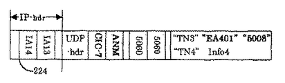
次に、電話機905−8が呼び出しに応答し(ステップB50)、この応答は無線基地局902−4、網ノード装置909−1、代理移動電話サーバ909−6を経て電話管理サーバ909−4に到達する(ステップ51乃至ステップ53)。電話管理サーバ909−4は、応答確認を無線基地局902−3へ返信することも可能である(ステップB60−1〜60−4、オプション)。電話管理サーバ909−4は電話応答を示すANMパケット224(図51)を形成して送出し、ANMパケット224が電話管理サーバ908−4に到達し、応答情報は代理移動電話サーバ908−6、網ノード装置908−1、無線基地局902−3を経て電話機905−6に到達する(ステップB54乃至B58)。なお、電話管理サーバ909−4は、前記ポート番号“5008”をANMパケット224に含めて、電話管理サーバ908−4へ知らせることも可能である(オプション)。電話機905−6は、応答確認を無線基地局902−3へ返信することも可能である(ステップB59、オプション)。
<<通信レコ−ドの設定>>
電話管理サーバ909−4は、CIC管理表909−4B(図60)を参照して通信レコ−ドの書込み情報を取得して表管理サーバ909−3に送信し(ステップB64)、表管理サーバ909−3は網ノード装置909−1内部の装置制御表910−4(図53)の4行目のレコ−ド“IA401,IA301,EA401,EA301,M255,M255,…”として設定する(ステップB65)。ここで、マスク情報M255 は、“255.255.255.255 ”とする。同様に、電話管理サーバ908−4は、CIC管理表908−4C(図57)を参照して通信レコ−ドの書込み情報を取得して表管理サーバ908−3に送信し(ステップB66)、表管理サーバ908−3は装置制御表910−3(図52)の3行目のレコ−ド“IA301,IA401,EA301,EA401,M255,M255,…”として設定する(ステップB67)。
<<通信フェーズ>>
電話機905−6と電話機905−8との電話通信には、装置制御表910−3(図52)内の前記設定した3行目のレコ−ド“IA301、IA401,EA301、EA401,M255,M255,…”と、装置制御表910−4(図53)の前記設定した4行目のレコ−ド“IA401、IA301,EA401、EA301,M255,M255,…”とが用いられる。電話機905−6の音声は無線通信路917−5(図31)を経由して転送され(ステップB68−1)、無線基地局902−3でデイジタル化された音声IPパケットはIP網内部を転送されて無線基地局902−4に到達し(ステップB68−2〜ステップB68−4)、無線基地局902−4において、電話音声が無線通信電波の形態で無線通信路917−6を伝送されて電話機905−8に到達する(ステップB68−5)。電話機905−8から送られたアナログ音声は、ディジタル化されてIPパケットに格納されて逆方向に送られる(ステップB69−1〜B69−5)。
<<無線通信領域の検出と移動準備手順>>
移動電話機905−6(図31)が移動して重複する無線通信領域205内に位置すると、移動電話機905−6zは無線基地局902−5から無線通信路917−10を経由して、無線基地局902−5の無線基地局識別記号“BS902-5”及び無線基地局902−5が接続する終端ゲートウェイ901−1の識別記号“GWE901-1”を取得する(図32のステップB80)。次に、図32及び図33内のステップの範囲230内のステップB81乃至B93について説明する。移動電話機905−6zは、電話番号“TN3”、宛先電話番号“TN4”、識別記号“GWE901-1”
及び“BS902-5”を無線通信路917−5yを経て無線基地局902−3に通知する(ステップB81、ハンドオーバ要求という)。無線基地局902−3は、電話番号“TN3”及び“TN4”、識別記号“GWE901-1”及び“BS902-5”を含むIPパケット225(図65)を形成して網ノード装置908−1に転送し(ステップB82)、網ノード装置908−1は、装置制御表910−3(図52)の第1行目のレコード“IA3,IA43,Kzero,EMB,Mzero,M255,…”を用いてIPパケット225をIPカプセル化して内部パケット226(図66)を形成して代理移動電話サーバ908−6に転送し(ステップB83)、代理移動電話サーバ908−6は、内部パケット226から内部パケット227(図67)を形成し、内部パケット227を電話管理サーバ908−4に転送する(ステップB84)。
Next, the telephone 905-8 responds to the call (step B50), and this response is sent to the telephone management server 909-4 via the radio base station 902-4, the network node device 909-1, and the proxy mobile telephone server 909-6. Reach (step 51 to step 53). The telephone management server 909-4 can also return a response confirmation to the radio base station 902-3 (steps B60-1 to 60-4, option). The telephone management server 909-4 forms and sends an ANM packet 224 (FIG. 51) indicating a telephone response, the
<< Communication Record Settings >>
The telephone management server 909-4 refers to the CIC management table 909-4B (FIG. 60), acquires communication record write information, and transmits it to the table management server 909-3 (step B64). 909-3 is set as the record “IA401, IA301, EA401, EA301, M255, M255,...” In the fourth row of the device control table 910-4 (FIG. 53) inside the network node device 909-1 (step). B65). Here, the mask information M255 is assumed to be “255.255.255.255”. Similarly, the telephone management server 908-4 refers to the CIC management table 908-4C (FIG. 57), acquires communication record write information, and transmits it to the table management server 908-3 (step B66). The table management server 908-3 sets the record “IA301, IA401, EA301, EA401, M255, M255,...” In the third row of the device control table 910-3 (FIG. 52) (step B67).
<< communication phase >>
For telephone communication between the telephone set 905-6 and the telephone set 905-8, the record “IA301, IA401, EA301, EA401, M255, M255 in the third row set in the device control table 910-3 (FIG. 52) is used. ,..., And the record “IA401, IA301, EA401, EA301, M255, M255,...” In the fourth row of the device control table 910-4 (FIG. 53) is used. The voice of the telephone 905-6 is transferred via the wireless communication path 917-5 (FIG. 31) (step B68-1), and the voice IP packet digitized by the wireless base station 902-3 is transferred inside the IP network. Then, the wireless base station 902-4 is reached (step B68-2 to step B68-4). In the wireless base station 902-4, telephone voice is transmitted through the wireless communication path 917-6 in the form of wireless communication radio waves. The telephone 905-8 is reached (step B68-5). The analog voice sent from the telephone 905-8 is digitized, stored in an IP packet, and sent in the reverse direction (steps B69-1 to B69-5).
<< Wireless Communication Area Detection and Movement Preparation Procedure >>
When the mobile phone 905-6 (FIG. 31) moves and is located in the overlapping
And “BS902-5” is notified to the wireless base station 902-3 via the wireless communication path 917-5y (step B81, referred to as a handover request). The radio base station 902-3 forms an IP packet 225 (FIG. 65) including telephone numbers “TN3” and “TN4” and identification symbols “GWE901-1” and “BS902-5” to form a network node device 908-1. (Step B82), and the network node device 908-1 uses the record “IA3, IA43, Kzero, EMB, Mzero, M255,...” In the first row of the device control table 910-3 (FIG. 52). The
電話管理サーバ908−4は、内部パケット227を受信して送信元電話番号“TN3”、宛先電話番号“TN4”、識別記号“GWE901-1”及び“BS902-5”を取出し、送信元電話番号“TN3”と宛先電話番号“TN4”とからCIC番号“CIC-7”を形成し、電話管理サーバ908−4が保持している複数のCIC管理表の内部から、“CIC-7”であるCIC管理表908−4C(図57)のレコードを見出し、そのメッセージ種別を“CON”に書き換える。“ハンドオーバ要求”であるので、次に電話管理サーバ908−4はサーバアドレス表211X(図38)を調べて、IPパケット227から取得した識別記号“GWE901-1”及び識別記号“BS902-5”を含むレコードは、サーバアドレス表211Xの表題部を除いた第1行目のレコード“GWE901-1,
TES906-4, IA11, BS902-5, EA1, IA1, MBS906-6, IA41, EMB”であることを知る。続いて、電話管理サーバ908−4は、前記レコード内の
“TES906-4”により定まる電話管理サーバ906−4のIPアドレス“IA11”、識別記号“BS902-5”により定まる無線基地局902−5のアドレス情報(外部IPアドレスは“EA1”、内部IPアドレスは“IA1”)及び移動代理電話サーバ906−6のアドレス情報(外部IPアドレスは“EMB”、内部IPアドレスは“IA41”)を得る。
The telephone management server 908-4 receives the
TES906-4, IA11, BS902-5, EA1, IA1, MBS906-6, IA41, EMB ”are known. Subsequently, the telephone management server 908-4 is determined by“ TES906-4 ”in the record. IP address “IA11” of telephone management server 906-4, address information of wireless base station 902-5 determined by identification symbol “BS902-5” (external IP address is “EA1”, internal IP address is “IA1”) and movement Address information of the proxy telephone server 906-6 (the external IP address is “EMB” and the internal IP address is “IA41”) is obtained.
電話管理サーバ908−4は、前記ソースアドレス“IA13”(電話管理サーバ908−4のアドレス)、宛先IPアドレス“IA11”である内部IPパケットを形成し、前記内部パケットは、電話管理サーバ906−4に向けて送出される(ステップB85)。但し、前記内部パケットはCIC番号“CIC-7”、送信元電話番号“TN3”、宛先電話番号“TN4”、CIC管理表908−4C(図57)から取得した情報“IA4,EA4,IA44,EMB、IA14,IA401,EA401,5008,UNI4”及び前記211Xを参照する手順により入手した情報“IA1,EA1,IA41,EMB”及び電話管理サーバ906−4のアドレス“IA11”を含む。電話管理サーバ906−4は前記内部パケットを受信し、前記内部パケットをコピーして、送信元電話番号“TN3”と宛先電話番号“TN4”とから定まるCIC番号“CIC-7”を有するCIC管理表のレコード906−4A(図62)を形成する(ステップB86)。ここで、CIC管理表906−4Aの手順区分はハンドオーバを示す“CON”とし、開始時刻“St6”としている。 The telephone management server 908-4 forms an internal IP packet having the source address “IA13” (address of the telephone management server 908-4) and the destination IP address “IA11”. 4 (step B85). However, the internal packet includes the CIC number “CIC-7”, the transmission source telephone number “TN3”, the destination telephone number “TN4”, and the information “IA4, EA4, IA44, EMB, IA14, IA401, EA401,5008, UNI4 ”and information“ IA1, EA1, IA41, EMB ”obtained by the procedure referring to the 211X and the address“ IA11 ”of the telephone management server 906-4 are included. The telephone management server 906-4 receives the internal packet, copies the internal packet, and manages the CIC having the CIC number “CIC-7” determined from the source telephone number “TN3” and the destination telephone number “TN4”. A table record 906-4A (FIG. 62) is formed (step B86). Here, the procedure classification of the CIC management table 906-4A is “CON” indicating handover and the start time “St6”.
電話管理サーバ906−4は、前記ハンドオーバ要求によって設定するディジタル音声通信路設定のための外部IPアドレスとポート番号を要求する内部IPパケット228(図68)を形成する。但し、内部IPパケット228内のアドレス情報(EA1,IA1,EMB,IA41)は、前記手順において取得している。電話管理サーバ906−4は、内部IPパケット228を代理移動電話サーバ906−6に送信し(ステップB87)、代理移動電話サーバ906−6は内部パケット228から、内部パケット229(図69)を形成して網ノード装置906−1に送信し(ステップB88)、網ノード装置906−1は受信した内部パケット229を逆カプセル化して外部パケット230(図70)を形成し、通信回線を経て無線基地局902―5に送信し(ステップB89)、無線基地局902−5は前記要求を受信すると音声通信路用の外部IPアドレスとポート番号の割り当てを行い、その内部に保持している無線基地局アドレス管理表212X(図39)に割り当て結果を記録する(ステップB90)。そして、割り当て結果の外部アドレス“EA101”、ポート番号“5012”、 無線回線識別記号“WC6”を含む外部パケット231(図71)を形成して網ノード装置906−1に送信する(ステップB91)。網ノード装置906−1は装置制御表910−1を用いて、受信した外部パケット231をカプセル化して内部パケット232(図72)を形成して代理移動電話サーバ906−6に送信する(ステップB92)。代理移動電話サーバ906−6は、受信した内部パケット222から内部パケット233(図73)を形成して電話管理サーバ906−4に送信する(ステップB93)。電話管理サーバ906−4は受信した内部パケット223から、無線回線識別記号
“WC6”、外部アドレス“EA101”及びポート番号“5012”を取得し、更に、電話管理サーバ906−4は、終端ゲートウェイアドレス管理表211(図37内)を、終端ゲートウェイアドレス管理表211Z(図37内)のように書換えて内部アドレス“IA101”を取得し、更に“IA101”に対応するレコード内の“UNI3”を取得し、前記により取得した“WC6、IA101、EA101、5012、UNI3”をCIC管理表906−4A(図62)に書き込み、結果はCIC管理表906−4B(図63)のようになる。
The telephone management server 906-4 forms an internal IP packet 228 (FIG. 68) for requesting an external IP address and port number for setting a digital voice communication path set by the handover request. However, the address information (EA1, IA1, EMB, IA41) in the
以上説明したステップB81〜ステップB93は、図32及び図33内のステップの範囲230に含まれる。要約すると、移動電話機905−6が移動電話機905−6yの位置に移動すると(図31)、CIC管理表906−4A(図62)の初期値は、移動電話機905−6の移動前に用いているCIC管理表908−4Cを参照して求める。
<<無線通信領域の検出と移動準備手順のバリエーション>>
前記ステップB81〜ステップB93のバリエーションとして、以下に述べるステップB80x、ステップB101乃至B105として実施可能である。移動電話機905−6が移動して無線通信領域203と205とが重複する範囲内に位置すると、移動電話機905−6zは、無線基地局902−3が接続する終端ゲートウェイ901−3を識別するための識別記号“GWE901-3”、無線基地局902−3の無線基地局識別記号“BS902-3”、送信元電話番号“TN3”及び宛先電話番号“TN4”を、無線通信路917−10を経て無線基地局902−5へ通知する(ステップB80x)。無線基地局902−5はハンドオーバ要求と判断し(ステップB100)、取得した前記識別記号“GWE901-3”、電話番号“TN3”及び“TN4”を、網ノード装置906−1を経て(ステップB101)、更に代理移動電話サーバ906−6を経て(ステップB102)、電話管理サーバ906−4へ通知する(ステップB103)。ステップB100乃至ステップB103は、ステップB90〜ステップB93と同様の手順である。電話管理サーバ906−4は、受信した内部パケットから、識別記号“GWE901-3”、電話番号“TN3”及び“TN4”を取得し、前記識別記号“GWE901-3”と電話管理サーバアドレス表211X(図38)とを用いて電話管理サーバ908−4のアドレス“IA13”を得る。次に、電話管理サーバ906−4は電話管理サーバ908−4に対して、移動電話機905−6のハンドオーバ要求(無線通信領域203から無線通信領域205への移動)が出された事実と、電話番号“TN3”、“TN4”
及び無線基地局902−3は、無線基地局アドレス管理表212Xを用いて取得したアドレス関連情報“EA101,5012,WC6”とを通知し(ステップB104)、電話管理サーバ908−4は、CIC番号“CIC−7”電話番号“TN3”及び“TN4”に対応するCIC管理表908−4C(図57)のレコード内の通信相手情報(IA4,EA4,IA44,EMB,IA14,IA401,EA401,5008,UNI4)を電話管理サーバ906−4に転送する(ステップB105)。
Step B81 to Step B93 described above are included in the
<< Variation of Wireless Communication Area Detection and Movement Preparation Procedure >>
Variations of Step B81 to Step B93 can be implemented as Step B80x and Steps B101 to B105 described below. When the mobile telephone 905-6 moves and is located within a range where the
The wireless base station 902-3 notifies the address related information “EA101, 5012, WC6” acquired using the wireless base station address management table 212X (step B104), and the telephone management server 908-4 receives the CIC number. Communication partner information (IA4, EA4, IA44, EMB, IA14, IA401, EA401, 5008) in the record of the CIC management table 908-4C (FIG. 57) corresponding to the “CIC-7” telephone numbers “TN3” and “TN4” , UNI4) is transferred to the telephone management server 906-4 (step B105).
以上説明したステップB100〜ステップB105は、図32及び図33内のステップの範囲231に含まれる。ステップB93又はステップB105の完了に続き、電話管理サーバ906−4は、終端ゲートウェイアドレス管理表211(図37内)を用いて“IA101、UNI3”を取得し、サーバアドレス表211X(図38)を用いて、アドレス情報“EA1,IA1,IA41,EMB”を取得し、電話管理サーバ906−4のアドレス“IA11”及び前記取得した各種情報“WC6,EA101,5012”を用いて、CIC管理表906−4B(図63)を形成する。なお、IP網900X内の全ての電話管理サーバは、サーバアドレス表211Xを保持している。ここで、無線基地局902−3が、移動電話機が個別の音声通信に用いる外部IPアドレス“EA101”、ポート番号“5012”及び無線回線識別記号“WC6”を含む無線基地局アドレス管理表を用いるようになっていることがポイントである。
<<装置制御レコードの設定指示>>
電話管理サーバ906−4はIPアドレス“IA101,IA401,EA101,EA401”を含む内部パケット234(図74)を形成し、表管理サーバ906−3経由(ステップB112)で網ノード装置906−1に転送し、網ノード装置906−1は前記IPアドレス情報を網ノ−ド装置906−1内部の装置制御表910−1(図54)の3行目のレコ−ド“IA101,IA401,EA101,EA401,M255,M255,…”として設定し(ステップB113)、その結果を返信する(ステップB114、B115)。更に、電話管理サーバ906−4は、IPアドレス“IA401,IA101,EA401,EA101”を含む内部パケット235(図75)を形成して電話管理サーバ909−4に送信し(ステップB120)、電話管理サーバ909−4は内部パケット235を受信して、表管理サーバ909−3経由で網ノード装置909−1に内部パケット236(図76)を転送し(ステップB122、B123)、網ノード装置909−1が装置制御表910−4(図53)内に前記IPアドレス情報を書き込み、その結果を返信する(ステップB124〜B126)。ステップB115及びステップB126の完了確認により(ステップB127)、移動電話機905−6が移動電話機905−6zの位置を経由して移動電話機905−6yの位置に移動し、電話通信を継続する切り替え準備が完了する。
<<切り替え動作の開始>>
電話管理サーバ906−4は切替え準備を確認すると(ステップB127)、ハンドオーバ切替え指示を含むIPパケット237(図77)を形成して電話管理サーバ908−4に送出し(図34及び図35内のステップB130)、IPパケット237に含まれる切替え指示情報は代理移動電話サーバ908−6、網ノード装置908−1を経て(ステップB131、B132)、IPパケット238(図78)として無線基地局902−3に到達し(ステップB133)、更に切替え指示情報は無線通信路917−5y(図31内)を経て移動電話機915−6zに到達する(ステップB134)。なお、電話管理サーバ908−4はステップB130の後、この時点以前に用いていたCIC管理表908−4C(図57)の利用を止めるため終了時刻“St3e”を書き込み、この結果得られるCIC管理表908−4Dは図58に示される。端末間通信接続制御に用いたCIC管理表908−4D(図58)を通信料金の課金などに用いることが可能であり、これに関しては特許文献2において開示されている。
Step B100 to step B105 described above are included in the
<< Device control record setting instruction >>
The telephone management server 906-4 forms an internal packet 234 (FIG. 74) including the IP addresses “IA101, IA401, EA101, EA401”, and passes through the table management server 906-3 (step B112) to the network node device 906-1. The network node device 906-1 transfers the IP address information to the records “IA101, IA401, EA101, 3rd row of the device control table 910-1 (FIG. 54) inside the network node device 906-1. EA401, M255, M255,... ”(Step B113), and the result is returned (steps B114, B115). Further, the telephone management server 906-4 forms an internal packet 235 (FIG. 75) including the IP addresses “IA401, IA101, EA401, EA101” and transmits it to the telephone management server 909-4 (Step B120). The server 909-4 receives the
<< Start of switching action >>
Upon confirming the switching preparation (step B127), the telephone management server 906-4 forms an IP packet 237 (FIG. 77) including a handover switching instruction and sends it to the telephone management server 908-4 (in FIG. 34 and FIG. 35). In step B130), the switching instruction information included in the
移動電話機915−6zは切替え指示に対する報告を無線基地局902−3に返信し(ステップB135)、無線基地局902−3は切替え報告を含むIPパケット239(図79)を形成して返信し、切替え報告は網ノード装置908−1、代理移動電話サーバ908−6を経て電話管理サーバ908−4に到達する(ステップB136乃至B138)。 The mobile telephone 915-6z returns a report to the switching instruction to the radio base station 902-3 (step B135), and the radio base station 902-3 forms and returns an IP packet 239 (FIG. 79) including the switching report, The switching report reaches the telephone management server 908-4 via the network node device 908-1 and the proxy mobile telephone server 908-6 (steps B136 to B138).
次に前記切替え報告は、IPパケット240(図80)に格納されて電話管理サーバ906−4に到達する(ステップB139)。前述と同様にして、電話管理サーバ906−4はハンドオーバ切替え指示を含むIPパケット241(図81)を形成して代理移動電話サーバ906−6に送出し(ステップB141)、前記切替え指示は網ノード装置906−1を経て(ステップB142)、IPパケット242(図82)として無線基地局902−5に到達し(ステップB143)、更に前記切替え指示は無線通信路917−10(図31内)を経て移動電話機915−6zに到達する(ステップB144)。移動電話機915−6zは切替え報告を無線基地局902−5に返信し(ステップB146)、無線基地局902−5は切替え報告を含むIPパケット243(図83)を形成して返信し、前記切替え報告は網ノード装置906−1、代理移動電話サーバ906−6を経て(ステップB147、B148)、IPパケット244(図84)に格納されて電話管理サーバ906−4に到達する(ステップB149)。更に、電話管理サーバ906−4は上述同様にハンドオーバ切替え指示を含むIPパケット245(図85)を形成して代理移動電話サーバ909−4に送出し(ステップB151)、電話管理サーバ909−4はステップ126(図33内)に作成していたCIC管理表909−4C(図61)の利用を開始し(ステップB152)、CIC管理表の切替え完了報告を返信する(ステップB153)。 Next, the switching report is stored in the IP packet 240 (FIG. 80) and reaches the telephone management server 906-4 (step B139). In the same manner as described above, the telephone management server 906-4 forms an IP packet 241 (FIG. 81) including a handover switching instruction and sends it to the proxy mobile telephone server 906-6 (step B141). After passing through the device 906-1 (step B142), it reaches the radio base station 902-5 as an IP packet 242 (FIG. 82) (step B143). Then, the mobile phone 915-6z is reached (step B144). The mobile phone 915-6z returns a switching report to the radio base station 902-5 (step B146), and the radio base station 902-5 forms and returns an IP packet 243 (FIG. 83) including the switching report. The report passes through the network node device 906-1 and the proxy mobile telephone server 906-6 (steps B147 and B148), is stored in the IP packet 244 (FIG. 84), and reaches the telephone management server 906-4 (step B149). Further, similarly to the above, the telephone management server 906-4 forms an IP packet 245 (FIG. 85) including a handover switching instruction and sends it to the proxy mobile telephone server 909-4 (step B151). The telephone management server 909-4 Use of the CIC management table 909-4C (FIG. 61) created in step 126 (in FIG. 33) is started (step B152), and a CIC management table switching completion report is returned (step B153).
次に、電話管理サーバ906−4は、ステップB66及びB67において設定していた装置制御表910−3(図52)内の第3行目のカプセル制御レコード“IA301,IA401,EA301,EA401,M255,M255,…”の利用終了を指示し、IPパケット246(図86)を形成して送信する(ステップB154)。IPパケット246を受信した電話管理サーバ908−4は、カプセル制御レコード利用終了指示を含むIPパケットを表管理サーバ908−3経由で網ノード装置908−1に送出し(ステップB157、B158)、電話管理サーバ908−4は、無線基地局アドレス管理表212(図39)内情報“EA301,5006,WC3”の利用終了指定を含むIPパケットを、代理移動電話サーバ908−6、網ノード装置908−1経由で無線基地局902−3に送出する(ステップB159乃至B161)。更に、電話管理サーバ906−4(図53)は、ステップB64及びB65(図33)において設定していた装置制御表910−4(図53)内の第4行目のカプセル制御レコード“IA401,IA301,EA401,EA301,M255,M255,…”の利用終了の指示を含むIPパケット247(図87)を形成して送信し(ステップB155)、IPパケット247を受信した電話管理サーバ909−4は、カプセル制御レコード利用終了指示を含むIPパケット247を、表管理サーバ909−3経由で網ノード装置909−1に送出する(ステップB157x、B158x)。
<<移動電話機専用の電話番号サーバの書き換え>>
電話管理サーバ906−4はCIC管理表906−4B(図63)の内部のレコードから、電話番号“TN3”と関連する内部アドレス情報(IA1,EA1,IA41,EMB,IA11,IA101,EA101)と自己のUNIの値“UNI3”を取り出し、電話番号“TN3”、IPアドレス“IA101,EA101,UNI3”を含むIPパケット248(図88)を形成して移動電話機専用の電話番号サーバ996に送信し(ステップB163)、IPパケット248の内容に従う書き換え完了が報告される(ステップB164)。この結果、電話番号サーバ996内部の移動電話機登録表210(図36)の第1行目のレコードは、“TN3,IA3,EA3,IA43,EMB,IA13,IA301,EA301、UNI3,PID3”から、“TN3,IA1,EA1,IA41,EMB,IA11,IA101,EA101、UNI3,PID3”(図89の表題部を除いた1行目)のように変更される。従って、後述する移動電話機の位置の変更手順を実施したと同等の結果となる。
<<内部IPアドレスの随時配布>>
電話管理サーバ909−4は、移動電話機専用の電話番号サーバ996に要求して内部IPアドレスを追加要求し、或いは配布済みの内部IPアドレスを電話番号サーバ996に返却することができる(ステップB165、オプション)。他の電話管理サーバも前述同様に電話番号サーバ996と交渉し、内部IPアドレスの追加配布や返却を要求することができる(オプション)。
<<解放フェ−ズ>>
図34及び図35内のステップB170〜ステップB192cに示す通話の解放フェーズは、本発明の前提とするIP網の呼接続制御手順(図6内のステップB70〜ステップB92c)とほぼ同様であり、以下に概説する。
Next, the telephone management server 906-4 uses the capsule control record “IA301, IA401, EA301, EA401, M255 in the third row in the device control table 910-3 (FIG. 52) set in steps B66 and B67. , M255,... "Is instructed, and the IP packet 246 (FIG. 86) is formed and transmitted (step B154). Upon receiving the
<< Rewriting the phone number server dedicated to mobile phones >>
The telephone management server 906-4 reads internal address information (IA1, EA1, IA41, EMB, IA11, IA101, EA101) associated with the telephone number “TN3” from the internal record of the CIC management table 906-4B (FIG. 63). It takes out its own UNI value “UNI3”, forms an IP packet 248 (FIG. 88) including the telephone number “TN3” and the IP addresses “IA101, EA101, UNI3” and sends it to the
<< Distribution of internal IP address as needed >>
The telephone management server 909-4 can request the mobile telephone dedicated
<< Liberation Phase >>
The call release phase shown in steps B170 to B192c in FIG. 34 and FIG. 35 is substantially the same as the call connection control procedure (step B70 to step B92c in FIG. 6) of the IP network as the premise of the present invention. Outlined below.
電話機905−6yの利用者が電話通信の解放を通知すると(図34のステップB170)、解放通知は無線基地局902−5、網ノ−ド装置906−1、代理移動電話サーバ906−6を経由して電話管理サーバ906−4に通知され(ステップB170〜B173)、電話管理サーバ906−4は、CIC管理表906−4B(図63)の中の回線番号が“CIC-7”であるレコ−ドの終了時刻の欄に終了時刻“St6e”を書き込む。次に、解放IPパケット250(図90,RELパケット)を形成して電話管理サーバ909−4へ通知し(ステップB174)、電話管理サーバ909−4は電話通信の解放指示を代理移動電話サーバ909−6、網ノード装置909−1を経て無線基地局902−4に通知する(ステップB176〜B178)。更に、電話管理サーバ909−4は、CIC管理表909−4C(図61)の中の回線番号が“CIC-7”であるレコ−ドの終了時刻の欄に終了時刻“St4e”を書込み、解放IPパケット250を受信したことを報告するために解放完了IPパケット251(図91、RLCパケット)を形成して電話管理サーバ906−4に返信する(ステップB184)。
When the user of the telephone set 905-6y notifies the release of the telephone communication (step B170 in FIG. 34), the release notice is sent to the radio base station 902-5, the network node device 906-1, and the proxy mobile telephone server 906-6. Is notified to the telephone management server 906-4 (steps B170 to B173), and the telephone management server 906-4 has the line number “CIC-7” in the CIC management table 906-4B (FIG. 63). Write the end time “St6e” in the record end time column. Next, a release IP packet 250 (FIG. 90, REL packet) is formed and notified to the telephone management server 909-4 (step B174), and the telephone management server 909-4 issues a telephone communication release instruction to the proxy
電話管理サーバ906−4はIPパケット251を受信すると、解放指示を無線基地局902−5に知らせる(ステップB185〜B187)。無線基地局902−5は、切断指示を電話機905−6yに通知することもできる(ステップB170−1、オプション)。一方、無線基地局902−4は切断指示を電話機905−8に通知すると共に(ステップB179)、解放報告を電話管理サーバ909−4に知らせる(ステップB181〜B183)。電話機905−8は、切断指示確認信号を無線基地局902−4へ送信することもできる(ステップB180、オプション)。
<<通信レコードの抹消>>
ステップB173の後に電話管理サーバ906−4は、解放IPパケット250(図90)の中に書き込んだ回線番号“CIC-7”を表管理サーバ906−3に送信し(ステップB196)、表管理サーバ906−3は対応する通信レコ−ド、本ケ−スでは装置制御表910−1(図54)の3行目のレコ−ド“IA101,IA401,EA101,EA401,M255,M255,…”を抹消する(ステップB197)。同様に、電話管理サーバ909−4はステップB176の後に、IPパケット250(図90)の中の回線番号“CIC-7”を取り出して、対応する通信レコ−ド(本ケ−スでは装置制御表910−4(図53)の2行目のレコ−ド“IA401,IA101,EA401,EA101,M255,M255,…”)の抹消を指示する(ステップB198、B199)。
<<解放報告オプションと無線チャネルの切断>>
以下、電話管理サーバ、無線基地局、移動電話機とを結ぶ通信路の解放手順(ステップB188a乃至B192c)が行われるが、これの手順は図6に示す通信路解放手順(ステップB88a乃至B92c)と同様である。
<<着信側移動電話機のハンドオーバ>>
上記実施例において、移動電話機905−6から移動電話機905−8へ電話呼出ししており、つまり移動電話機905−6が発呼電話機、移動電話機905−8が着呼電話機である。ステップB80(図32)において、移動電話機905−6が無線通信領域203内から無線通信領域205内に移動し、移動電話機905−6の接続する無線基地局が切り替わりを含むハンドオーバが生じている。つまり、発呼電話機の移動によりハンドオーバが生じている。
Upon receiving the
<< Deletion of communication record >>
After step B173, the telephone management server 906-4 transmits the line number “CIC-7” written in the release IP packet 250 (FIG. 90) to the table management server 906-3 (step B196). Reference numeral 906-3 denotes a corresponding communication record. In this case, the record “IA101, IA401, EA101, EA401, M255, M255,...” In the third row of the device control table 910-1 (FIG. 54) is displayed. It is deleted (step B197). Similarly, the telephone management server 909-4 extracts the line number “CIC-7” in the IP packet 250 (FIG. 90) after step B176, and the corresponding communication record (device control in this case). Deletion of the record “IA401, IA101, EA401, EA101, M255, M255,...” In the second row of Table 910-4 (FIG. 53) is instructed (steps B198, B199).
<< Release Report Option and Radio Channel Disconnect >>
Hereinafter, a communication path releasing procedure (steps B188a to B192c) connecting the telephone management server, the radio base station, and the mobile phone is performed. This procedure is the same as the communication path releasing procedure (steps B88a to B92c) shown in FIG. It is the same.
<< Handover of incoming mobile phone >>
In the above embodiment, the mobile telephone 905-6 makes a telephone call to the mobile telephone 905-8, that is, the mobile telephone 905-6 is the calling telephone and the mobile telephone 905-8 is the incoming telephone. In Step B80 (FIG. 32), the mobile phone 905-6 moves from the
一方、ハンドオーバを実施するための通信手順(ステップB80〜B165)は、発呼電話機と着呼電話機間の電話呼接続制御の通信手順(ステップB01〜B60−4)とは、直接の関係はなく、移動電話機905−6(発呼側電話機)からの通信手順と移動電話機905−8(着呼側電話機)からの通信手順が対照的といえる。この理由から、着呼電話機の移動によるハンドオーバが可能であり、例えば移動電話機905−6から移動電話機905−8へ電話を電話呼出しして、電話通信を継続し、次に、移動電話機905−8が無線基地局902−1(図1)の無線通信領域に属する電話機905−7の位置に移動し、移動電話機905−6から移動電話機905−8y(電話機905−7の位置に移動した移動電話機905−8)と電話通信を継続することが可能である。即ち、移動電話機905−6、無線基地局902−3、終端ゲートウェイ901−3、終端ゲートウェイ901−2、無線基地局902−1、移動電話機905−8yを経由する電話通信路により電話通信を継続できる。ただし、無線基地局902−1の無線通信領域と無線基地局902−4の無線通信領域との領域が一部分重複するケースである。まとめると、着呼電話機の移動によりハンドオーバが生じて、電話通信を継続することができる。
<<同じ終端ゲートウェイに接続する無線基地局に移動するバリエーション>>
図92乃至図95は、移動電話機905−6が、無線基地局902−3、終端ゲートウェイ901−3、終端ゲートウェイ901−4、無線基地局902−4を経由して移動電話機905−8と電話通信を継続し、次の段階として、移動電話機905−6が無線通信領域203内から無線通信領域202(図31)内に移動し、移動電話機905−6w、無線基地局902−2、終端ゲートウェイ901−3、終端ゲートウェイ901−4、無線基地局902−4を経由して、移動電話機905−8を結ぶ電話通信を継続できる通信手順を示している。ここで、移動電話機905−6wは、無線通信範囲202内に移動した電話機905−6である。
On the other hand, the communication procedure (steps B80 to B165) for carrying out the handover is not directly related to the communication procedure (steps B01 to B60-4) of the telephone call connection control between the calling phone and the called phone. The communication procedure from the mobile telephone 905-6 (calling telephone) and the communication procedure from the mobile telephone 905-8 (calling telephone) are in contrast. For this reason, handover by moving the incoming telephone is possible, for example, a telephone call is made from the mobile telephone 905-6 to the mobile telephone 905-8 to continue telephone communication, and then the mobile telephone 905-8. Moved to the position of the telephone 905-7 belonging to the wireless communication area of the wireless base station 902-1 (FIG. 1), and moved from the mobile telephone 905-6 to the mobile telephone 905-8y (mobile telephone moved to the position of the telephone 905-7) 905-8) and telephone communication can be continued. That is, the telephone communication is continued through the telephone communication path via the mobile telephone 905-6, the radio base station 902-3, the termination gateway 901-3, the termination gateway 901-2, the radio base station 902-1, and the mobile telephone 905-8y. it can. However, the wireless communication area of the wireless base station 902-1 and the wireless communication area of the wireless base station 902-4 partially overlap. In summary, a hand-over occurs due to the movement of the incoming telephone, and the telephone communication can be continued.
<< Variation to move to a radio base station connected to the same terminal gateway >>
92 to 95, the mobile telephone 905-6 makes a call to the mobile telephone 905-8 via the radio base station 902-3, the termination gateway 901-3, the termination gateway 901-4, and the radio base station 902-4. As a next step, the mobile telephone 905-6 moves from the
図92及び図93は、図32と図33とから終端ゲートウェイ901−1が関与する通信範囲901−1xを除いた形態の通信手順となっている。同様に、図94と図95は、図34と図35とから終端ゲートウェイ901−1が関与する通信範囲901−1xを除いた形態の通信手順となっている。図92及び図93において、ステップK1及びステップK7は、図32及び図33におけるステップK1及びステップK7と同一の機能、即ち移動電話機専用の電話番号サーバ996からの内部アドレスの配送手順を示している。また、図92及び図93において、ステップB01〜ステップB60−4は、図32及び図33におけるステップB01〜ステップB60−4と同一の機能、即ち移動電話機専用の電話番号サーバ996からの内部アドレスの配送手順を示している。図92及び図93において、ステップB68−1〜ステップB69−5は、図32及び図33におけるステップB68−1〜ステップB69−5と同一の機能、即ち移動電話機905−6及び移動電話機905−6との間のディジタル音声パケットを送受する電話通信を示している。
92 and 93 show communication procedures in a form in which the communication range 901-1x involving the termination gateway 901-1 is excluded from FIGS. 32 and 33. Similarly, FIG. 94 and FIG. 95 show communication procedures in a form in which the communication range 901-1x involving the terminating gateway 901-1 is excluded from FIG. 34 and FIG. 92 and 93, Step K1 and Step K7 show the same function as Step K1 and Step K7 in FIG. 32 and FIG. 33, that is, the internal address delivery procedure from the
図92及び図95において、ステップB80〜ステップB164xは、移動電話機905−6の位置が移動電話機905−6w(図31)の位置に移動し、移動電話機905−6w、無線基地局902−2、終端ゲートウェイ901−3、終端ゲートウェイ901−4、無線基地局902−4、移動電話機905−8である電話通信路の切替え手順(切替え手順2)を示している。一方、切替手順1、即ち図32及び図35において、ステップB80〜ステップB164は、移動電話機905−6の位置が移動電話機905−6y(図31)の位置に移動し、移動電話機905−6y、無線基地局902−5、終端ゲートウェイ901−1、終端ゲートウェイ901−4、無線基地局902−4、移動電話機905−8である電話通信路の切替え手順となっている。切替手順1において無線基地局902−5を無線基地局902−2に置き換え、終端ゲートウェイ901−1を終端ゲートウェイ901−3に置き換え、移動電話機905−6yを移動電話機905−6wに同時に置き換えて切替手順2が得られる。図92乃至図95内に示すステップB86x、B120x、B151x、B164x等は、図32乃至図35内に示すステップB86、B120、B151、B164等と同様の機能を遂行し、異なる点は、終端ゲートウェイ901−1内部の手順を終端ゲートウェイ901−3内部の手順に置き換えていることである。
92 and 95, in steps B80 to B164x, the position of the mobile telephone 905-6 moves to the position of the mobile telephone 905-6w (FIG. 31), and the mobile telephone 905-6w, the radio base station 902-2, The telephone communication path switching procedure (switching procedure 2), which is the termination gateway 901-3, termination gateway 901-4, radio base station 902-4, and mobile phone 905-8, is shown. On the other hand, in the
図92及び図93において、ステップB168−1乃至ステップB169−5及びステップB170以降の通信手順と同様である。以上の理由から、着呼電話機の移動によりハンドオーバが生じ、電話通信を継続することができる。
<<移動電話機の電話番号登録>>
移動電話機を用いるための電話番号登録手順を図96に示しており、この登録手順は、特許文献2として図7に示す移動電話機の電話番号登録手順の一部を変更した技法となっており、下記に説明する。
92 and 93, the communication procedure is the same as that after step B168-1 to step B169-5 and step B170. For the above reasons, handover occurs due to the movement of the incoming telephone, and telephone communication can be continued.
<< Mobile phone number registration >>
The telephone number registration procedure for using a mobile telephone is shown in FIG. 96, and this registration procedure is a technique in which a part of the mobile telephone telephone number registration procedure shown in FIG. This is explained below.
移動電話機905−6を使用するユーザ990−2(図1内)は、移動電話機905−6が用いる電話番号“TN3”、移動電話機905−6の認証情報”PID3”及びユーザ名や通信料金の支払い方法を含めて電話受付者991−2に申込み(ステップV1)、ユーザサービスサーバ992−2(図1内)を経て(ステップV2、V3)、電話番号サーバに通知される(ステップV4)。電話番号サーバ996は、電話番号“TN3”及び移動電話機905−6の認証情報“PID3”を、移動電話機専用の電話番号サーバ996の内部の移動電話機登録表210(図36)に保持する(ステップV5)。なお、ステップV3において、ユーザサービスサーバ992−2は、電話番号“TN3”、認証情報”PID3”、申し込みユーザ名、通信料金の支払い方法を、ユーザサービス管理下のデータベースに保持している。移動電話機登録表210の表題部を除いた第1行目のレコード“TN3,IA3,EA3,IA43,EMB,IA13,IA301,EA301,UNI3,PID3”のうち“TN3”及び“PID3”は前記手順(ステップV1乃至V5)により格納されている。IP網900(図1)の電話受付者991−2が前記手順に介入していることが特徴であり、電話番号“TN3”の利用者を特定できるので通信料金の課金が確実となっている。
<<電話機の初期位置の登録>>
次に、電話機の初期位置の登録手順を説明する。無線基地局902−3は、移動電話機905−6と情報交換して通信可能性を確認し(図96のステップV10)、通信可能性が確認されると、移動電話機905−6は位置登録情報を無線基地局902−3に向けて発信する(ステップV11)。位置登録情報は電話番号“TN3”、認証情報”PID3”を含む。無線基地局902−3は位置登録情報を含む外部IPパケット271(図98)を形成し、網ノード装置908−1に送信する(ステップV12)。外部IPパケット271は、無線基地局アドレス管理表212(図39)を参照して取得した外部IPアドレス“EA301”、前記取得した電話番号“TN3”、認証情報”PID3”及び無線基地局902−3の識別記号“BS902-3”を含む。外部IPパケット271は網ノード装置902−3を経て、内部パケット272(図99)となり、内部パケット272は代理移動電話サーバ908−6に送られる(ステップV13)。代理移動電話サーバ908−6は受信した内部パケット272から内部パケット273(図100)を形成し、内部パケット273は電話管理サーバ908−4に送られる(ステップV14)。
The user 990-2 (in FIG. 1) who uses the mobile telephone 905-6 has the telephone number “TN3” used by the mobile telephone 905-6, the authentication information “PID3” of the mobile telephone 905-6, the user name and the communication fee. An application is made to the telephone receptionist 991-2 including the payment method (step V1), and the user service server 992-2 (in FIG. 1) (steps V2 and V3) is notified to the telephone number server (step V4). The
<< Registering the initial position of the phone >>
Next, a procedure for registering the initial position of the telephone will be described. The radio base station 902-3 exchanges information with the mobile phone 905-6 to confirm the communication possibility (step V10 in FIG. 96). When the communication possibility is confirmed, the mobile phone 905-6 receives the location registration information. Is transmitted to the radio base station 902-3 (step V11). The location registration information includes a telephone number “TN3” and authentication information “PID3”. The radio base station 902-3 forms an external IP packet 271 (FIG. 98) including location registration information, and transmits it to the network node device 908-1 (step V12). The
電話管理サーバ908−4は、受信したIPパケット273から電話番号“TN3”、認証情報“PID3”、各種アドレス(EA301、IA3,EA3,IA43,EMB)を取得し、更に内部パケット273の送信元IPアドレス“IA43”(代理移動電話サーバ908−6の内部IPアドレス)を用いて、終端ゲートウェイアドレス管理表211(図37)を検索して、送信元IPアドレス“IA43”に対応する内部IPアドレス“IA301”及びUNI(ユーザネットワークインタフェース)の“UNI3”を取得し、電話番号“TN3”、各種IPアドレス(IA3,EA3,IA43,EMB,IA13,IA301,EA301),前記“UNI3”,前記“PID3”を含むIPパケット274(図101)を形成し、電話番号サーバ996に送信する(ステップV15)。ここで、電話管理サーバ908−4は、そのアドレス“IA13”を追加している。
The telephone management server 908-4 acquires the telephone number “TN3”, the authentication information “PID3”, and various addresses (EA301, IA3, EA3, IA43, EMB) from the received
電話番号サーバ996は内部パケット274を受信し、電話番号サーバ996は、電話番号の登録ステップV7において保持している電話番号“TN3”及び認証情報“PID3”と、ステップV15において取得した電話番号“TN3”及び認証情報”PID3”とを比較し、端末認証結果が合格か不合格かを判定する(ステップV16)。合格であれば外部IPアドレス“EA301”、電話番号“TN3”及び認証情報“PID3”を移動電話機登録表210(図36)のレコードに書き込む。この結果、移動電話機登録表210(図36)の表題部を除いた第1行目のレコード“TN3、IA3,EA3,IA43,EMB,IA13,IA301,EA301,UNI3、“PID3”が得られる。前記認証結果は前記逆方向に、移動電話機905−6に報告される(ステップV17〜ステップV21)。
<<移動電話機の位置変更>>
移動電話機の初期位置登録の手順を完了している状態において、移動電話機905−6がその所在位置を変更し、新しい移動電話機の位置を登録することができる。電話番号“TN8”である移動電話機が初期位置登録の手順を完了しており、移動電話機専用の電話番号サーバ996内部の移動電話機登録表(図36)第3行目のレコード“TN8,IA8,EA8,IA48,EMB,IA18,IA801,EA801,UNI8,PID8”となっているケースである。前記移動電話機(電話番号“TN8”)が電話機905−5(図1内)へ位置を変更するケースを、図97を参照して説明する、
移動電話機905−5は無線基地局902−2と情報交換して通信可能性を確認し(ステップV10x)、通信可能性が確認されると、移動電話機905−5は位置変更情報を無線基地局902−2に向けて発信する(ステップV11x)。位置変更情報は電話番号“TN8”、認証情報”PID8”を含む。無線基地局902−2は位置変更情報を含む外部IPパケット275(図102)を形成し、網ノード装置908−1に送信する(ステップV12x)。以下、前記移動電話機の初期位置登録と同様の手順を行い(ステップV13x、ステップ14x)、電話管理サーバ908−4は内部パケット276(図103)を形成し、電話番号サーバ996に送信する(ステップ15x)。前記認証の結果は前記逆方向に、移動電話機905−6に報告される(ステップV17x〜ステップV21x)。電話番号サーバ996は内部パケット276を受信し、移動電話機登録表210(図36)の第3行目のレコード“TN8,IA8,EA8,IA48,EMB,IA18,IA851,EA801,UNI8,PID8”は移動電話機登録表210X(図89)のように書き換えられる(ステップ16x)。ここで、内部IPアドレス“IA851”への書き換えは、IPパケット276内の内部IPアドレス“IA851”により変更指定されている。
<<ルート電話番号サーバ>>
IP網900X(図31)を大規模化した他の移動電話通信の実施方法を、図104を参照して説明する。
The
<< Mobile phone position change >>
In a state where the procedure for registering the initial position of the mobile telephone is completed, the mobile telephone 905-6 can change its location and register the position of the new mobile telephone. The mobile telephone having the telephone number “TN8” has completed the initial location registration procedure. The mobile telephone registration table (FIG. 36) in the third
The mobile telephone 905-5 exchanges information with the radio base station 902-2 to confirm the communication possibility (step V10x). When the communication possibility is confirmed, the mobile telephone 905-5 transmits the position change information to the radio base station. A call is sent to 902-2 (step V11x). The location change information includes a telephone number “TN8” and authentication information “PID8”. The radio base station 902-2 forms the external IP packet 275 (FIG. 102) including the location change information and transmits it to the network node device 908-1 (step V12x). Thereafter, the same procedure as the initial location registration of the mobile phone is performed (step V13x, step 14x), and the telephone management server 908-4 forms an internal packet 276 (FIG. 103) and transmits it to the telephone number server 996 (step). 15x). The result of the authentication is reported to the mobile phone 905-6 in the reverse direction (step V17x to step V21x). The
<< Root phone number server >>
Another method for carrying out mobile telephone communication in which the
259−1乃至259−3はIP網、260−1乃至260−5は無線基地局、261−1乃至261−3はメディアルータ、962−1乃至963−5は終端ゲートウェイ、263−1乃至263−3は中継ゲートウェイ、264−1乃至254−3は移動電話機、265−1乃至265−3は固定電話機、996−1乃至996−3は移動電話機専用の電話番号サーバ、996−4は移動電話機専用のルート電話番号サーバである。中継ゲートウェイの間はIP通信回線で接続される。IP網259−1乃至259−3は、例えば通信事業者により個別に管理される。 259-1 to 259-3 are IP networks, 260-1 to 260-5 are radio base stations, 261-1 to 261-3 are media routers, 962-1 to 963-5 are termination gateways, 263-1 to 263 -3 is a relay gateway, 264-1 to 254-3 are mobile telephones, 265-1 to 265-3 are fixed telephones, 996-1 to 996-3 are dedicated telephone number servers, and 996-4 is a mobile telephone. It is a dedicated route telephone number server. The relay gateways are connected by an IP communication line. The IP networks 259-1 to 259-3 are individually managed by, for example, a communication carrier.
終端ゲートウェイ262−1乃至262−5は終端ゲートウェイ901−1(図1)と同様のサーバを含む構成であり、例えば個別の電話管理サーバや代理移動電話サーバを含む。中継ゲートウェイ263−1乃至263−4は、特許文献2においてIP網間をIP通信回線により接続する中継ゲートウェイとして説明されている。移動電話機専用の電話番号サーバ996−1乃至996−3は本実施例において、移動電話機専用の電話番号サーバ996と同様の機能を有し、それぞれIP網259−1乃至259−3内部において、電話番号からIPアドレスなどを回答する処理を実施している。ルート電話番号サーバ996−4は電話番号サーバ996−1乃至996−3及びIPパケットを送受し、電話番号からIPアドレスを回答するなどの処理を実施できることは、特許文献2の電話番号サーバを説明している図と同様である。例えば、電話番号サーバ996−1からルート電話番号サーバ996−4を経て、電話番号サーバ996−2が管理している電話番号“TN30”に対応するIPアドレスなどを問い合わせて回答を得ることができる(図105、図106)。
<<複数の移動電話機専用の電話番号サーバのまとめ>>
IP網は複数のIP網Nl、…、Nk(k=1,2,…)で成っており、IP網N−mとIP網N−nとはIP通信回線を経て直接に或いは他のIP網N−kを経て間接的に接続されており、IP網Nmは移動電話機専用の電話番号サーバNmを含み、移動電話機専用のルート電話番号サーバはIP網Nmの何れかに含まれる。電話番号サーバはNmは移動電話機専用のルート電話番号サーバを経て、電話番号サーバNnの有する電話番号に関連するIPアドレスと関連情報を取得することができ、前記複数の移動電話機専用のルート電話管理サーバを用いて、移動電話機1−無線基地局3−IP網Nm−IP網Nn−無線基地局2−移動電話機2又は固定電話機2である通信路を経由する電話通信しながら、移動電話機1が無線基地局の無線通信領域3の範囲内に移動し、移動電話機1−無線基地局3−IP網Nm−IP網Nn−無線基地局2−移動電話機2又は固定電話機2と電話通信を継続すること(ハンドオーバ)が可能である。
<<固定電話機から移動電話機への電話呼び出し>>
図107は特許文献2において開示されている固定電話機905−1から移動電話機905−8への接続制御手順である。図107の左側半分の通信手順は、電話機905−1(図1)が発信側となる呼接続制御手順を示しており、図2の左側半分の通信手順と同様である。また、図107の右側半分の通信手順は、電話機905−8(図1)が着信側となる呼接続制御手順を示しており、図5の右側半分の通信手順と同様である。このようになっているから、固定電話機905−1から移動電話機905−8への呼接続制御を実施し、前記電話機間において電話通信を行うことができる。
The termination gateways 262-1 to 262-5 are configured to include a server similar to the termination gateway 901-1 (FIG. 1), and include, for example, individual telephone management servers and proxy mobile telephone servers. The relay gateways 263-1 to 263-4 are described in
<< Summary of telephone number servers dedicated to multiple mobile phones >>
The IP network is composed of a plurality of IP networks Nl,..., Nk (k = 1, 2,...), And the IP network Nm and the IP network Nn can be directly connected to each other via IP communication lines or other IP networks. An IP network Nm includes a telephone number server Nm dedicated to a mobile telephone, and a root telephone number server dedicated to a mobile telephone is included in any of the IP networks Nm. The telephone number server Nm can obtain the IP address and related information related to the telephone number of the telephone number server Nn via the root telephone number server dedicated to the mobile telephone, and the root telephone management dedicated to the plurality of mobile telephones. While using the server, the
<< Telephone call from fixed telephone to mobile telephone >>
FIG. 107 shows a connection control procedure from the fixed telephone 905-1 to the mobile telephone 905-8 disclosed in
固定電話機905−1から移動電話機905−8へ電話呼出しして、移動電話機905−8が、無線基地局902−1の無線通信領域に属する電話機905−7(図1)の位置に移動して、移動電話機905−8から移動電話機905−8y(電話機905−7の位置に移動した移動電話機905−8)と電話通信を継続することが可能である。即ち、固定電話機905−1、メディアルータ903−1、終端ゲートウェイ901−1、終端ゲートウェイ901−2、無線基地局902−1、移動電話機905−8yを経由する電話通信路により電話通信を継続できる。ただし、無線基地局902−1の無線通信領域と無線基地局902−4の無線通信領域との領域が一部分重複するケースである。まとめると、固定電話機と移動電話機との間の電話通信において、着呼側移動電話機の移動によりハンドオーバが生じて電話通信を継続することができる。
<<移動電話機から固定電話機への電話呼び出し時のハンドオーバ>>
図108乃至図111は、移動電話機905−6が発信側電話機、固定電話機905−4が着信側電話機となり、移動電話機905−6が無線通信領域203(図31)から無線通信領域205へ移動(ハンドオーバー)するケースについての通信手順(以降、通信手順108という)を説明している。一方、図32乃至図35は、移動電話機905−6が発信側電話機、移動電話機905−8が着信側電話機となり、移動電話機905−6が無線通信領域203(図31)から無線通信領域205へ移動するケースについての通信手順(以降、通信手順32という)を説明している。通信手順32は、着信側電話機が移動電話機905−8であり、通信手順108は固定電話機905−4(図108乃至図111)に変更しているが、発信側電話機905−6のハンドオーバーに関しては同一である。
When a telephone call is made from the fixed telephone 905-1 to the mobile telephone 905-8, the mobile telephone 905-8 moves to the position of the telephone 905-7 (FIG. 1) belonging to the radio communication area of the radio base station 902-1. The telephone communication can be continued from the mobile telephone 905-8 to the mobile telephone 905-8y (the mobile telephone 905-8 moved to the position of the telephone 905-7). That is, the telephone communication can be continued through the telephone communication path via the fixed telephone 905-1, the media router 903-1, the termination gateway 901-1, the termination gateway 901-2, the radio base station 902-1, and the mobile telephone 905-8y. . However, the wireless communication area of the wireless base station 902-1 and the wireless communication area of the wireless base station 902-4 partially overlap. In summary, in the telephone communication between the fixed telephone and the mobile telephone, a handover occurs due to the movement of the called mobile telephone, and the telephone communication can be continued.
<< Handover when calling from a mobile phone to a fixed phone >>
108 to 111, the mobile telephone 905-6 is a caller telephone, the fixed telephone 905-4 is a callee telephone, and the mobile telephone 905-6 moves from the wireless communication area 203 (FIG. 31) to the wireless communication area 205 ( A communication procedure (hereinafter referred to as a communication procedure 108) for a case of handover) is described. On the other hand, in FIGS. 32 to 35, the mobile telephone 905-6 is a calling telephone, the mobile telephone 905-8 is a receiving telephone, and the mobile telephone 905-6 moves from the wireless communication area 203 (FIG. 31) to the
固定電話機への変更に対応して図108乃至図111に示す通信手順の第1の相違点は、電話管理サーバ908−4が、電話番号の検索を行うステップB07、B08、B07y,B08y(図108、図109)と、電話番号の検索を行うステップB07x及びB08x(図32、図33)とである。通信手順の第2の相違点は、終端ゲートウェイ901−4内部の通信手順901−4xの相違であり、着信側電話機が固定電話機905−4であるので、移動電話機で必要であった認証手順(図33内のステップB26,B27a乃至B28d、B204乃至B206,B190a乃至B192c等)を省いていることである。前記以外の他の通信手順は変更しておらず、呼接続制御の本質は変わらない。このようになっているから、移動電話機905−6から固定電話機905−4への呼接続制御を実施し、前記電話機間において電話通信を行うことができる。このようにして、固定電話機と移動電話機間の電話通信において、着呼側移動電話機の移動によりハンドオーバが生じ、電話通信を継続することができる。
<<固定端末を呼出し中の移動電話機のハンドオーバ>>
固定電話機905−4と通信中の移動電話機905−6(図31)とが、位置905−6から位置905−6yに移動するハンドオーバの実施例を、図108、図109、図110及び図111を参照して前述している。以下では、この実施例において、固定電話機905−4(図31)をIP端末905−17に切り替えた実施例を説明する。ここで、固定電話機905−4及びIP端末905−17とも、メディアルータ903−4に接続されている(図31)。図108、図112、図110、図113を用いて説明する。
Corresponding to the change to the fixed telephone, the first difference in the communication procedure shown in FIGS. 108 to 111 is that the telephone management server 908-4 searches for telephone numbers in steps B07, B08, B07y, B08y (FIG. 108 and FIG. 109) and steps B07x and B08x (FIGS. 32 and 33) for searching for telephone numbers. The second difference in the communication procedure is the difference in the communication procedure 901-4x inside the terminating gateway 901-4. Since the receiving side telephone is the fixed telephone 905-4, the authentication procedure (required for the mobile telephone) Steps B26, B27a to B28d, B204 to B206, B190a to B192c, etc.) in FIG. 33 are omitted. Other communication procedures other than the above are not changed, and the essence of the call connection control is not changed. Thus, call connection control from the mobile telephone 905-6 to the fixed telephone 905-4 can be performed, and telephone communication can be performed between the telephones. In this way, in the telephone communication between the fixed telephone and the mobile telephone, a handover occurs due to the movement of the called mobile telephone, and the telephone communication can be continued.
<< Handover of mobile phone calling a fixed terminal >>
FIG. 108, FIG. 109, FIG. 110, and FIG. 111 show an example of handover in which the fixed telephone 905-4 and the mobile telephone 905-6 (FIG. 31) in communication move from the position 905-6 to the position 905-6y. As described above. Hereinafter, an example in which the fixed telephone 905-4 (FIG. 31) is switched to the IP terminal 905-17 will be described. Here, both the fixed telephone 905-4 and the IP terminal 905-17 are connected to the media router 903-4 (FIG. 31). This will be described with reference to FIGS. 108, 112, 110, and 113.
始めに、図109と図112は類似しているので、それらの相違点を確認する。図109に示す固定電話機905−4を、図112においてIP端末905−17へ切り替えており、この切り替えに伴って、図109内に示す電話機905−4に関連するステップ“A25”,“A40”,“A50”,“A60”,“B68−5”,“B69−1”を、図112内に示すIP端末905−17に関連するステップ“A25x”,“A40x”,“A50x”,“A60x”,“B68−5x”,“B69−1x”へ切り替えている。更に、図111と図113は類似しているので、それらの相違点を確認する。図111に示す固定電話機905−4を、図113においてIP端末905−17へ切り替えており、この切り替えに伴って、図111内に示す電話機905−4に関連するステップ“B168−5”,“B169−1”,“A179”,“A180”を、図113内に示すIP端末905−17に関連するステップ“B168−5x”,“B169−1x”,“A179x”,“A180x”へ切り替えている。 First, since FIG. 109 and FIG. 112 are similar, the difference between them is confirmed. The fixed telephone 905-4 shown in FIG. 109 is switched to the IP terminal 905-17 in FIG. 112, and the steps “A25” and “A40” related to the telephone 905-4 shown in FIG. , “A50”, “A60”, “B68-5”, “B69-1” are replaced with steps “A25x”, “A40x”, “A50x”, “A60x” related to the IP terminal 905-17 shown in FIG. "," B68-5x "," B69-1x ". Furthermore, since FIG. 111 and FIG. 113 are similar, the difference between them is confirmed. The fixed telephone 905-4 shown in FIG. 111 is switched to the IP terminal 905-17 in FIG. 113, and the steps “B168-5”, “related to the telephone 905-4 shown in FIG. B169-1 ”,“ A179 ”, and“ A180 ”are switched to steps“ B168-5x ”,“ B169-1x ”,“ A179x ”, and“ A180x ”related to the IP terminal 905-17 shown in FIG. Yes.
このようになっているから、IP端末905−17が前記ステップ“A25x”,“A40x”,“A50x”,“A60x”,“B68−5x”,“B69−1x”を実行し、更に“B168−5x”,“B169−1x”,“A179x”,“A180x”を実行することにより、移動電話機905−6からIP端末905−17との電話通信において、移動電話機905−6の移動によるハンドオーバが生じたときも、電話通信を継続することができることが説明できる。なお、移動電話機905−6が、905−6の位置(図31)から905−6yに移動するハンドオーバが可能であることは、図108、図109、図110及び図111を参照して、上述で説明している通信手順をそのまま採用している。 Since this is the case, the IP terminal 905-17 executes the steps "A25x", "A40x", "A50x", "A60x", "B68-5x", "B69-1x", and further "B168" −5x ”,“ B169-1x ”,“ A179x ”,“ A180x ”allows the mobile telephone 905-6 to perform handover due to movement of the mobile telephone 905-6 in the telephone communication from the mobile telephone 905-6 to the IP terminal 905-17. It can be explained that telephone communication can be continued even when it occurs. The fact that the mobile phone 905-6 can be handed over from the position 905-6 (FIG. 31) to 905-6y is described above with reference to FIGS. 108, 109, 110 and 111. The communication procedure described in is used as it is.
IP端末905−17は移動電話機905−6からの要求(ステップB68−5x、ステップB168−5x)に応じて、各種のデータを提供すること(ステップB69−1x、ステップB169−1x)が可能である。即ち、IP端末905−17は移動電話機905−6からの要求に応じて、各種データを提供するデータ提供サーバや、WWWサーバとして機能することが可能となっている。
<<まとめ>>
IP網に接続する電話機や無線端末、音声画像装置の地理的位置を移動しながら端末間通信を継続するため電話管理サーバを複数設置し、電話管理サーバは電話機の地理的位置を変更するための一連の呼接続制御手順を実施する。IP網は、移動電話機1と移動電話機2との間の移動電話機間通信、移動電話機と固定電話機又はIP端末との間でIP網を経由して電話通信を行うことが可能であり、移動電話機は電話通信中に少なくとも無線基地局を変えて電話通信を継続するハンドオーバ通信が可能である。ハンドオーバを実施すると、移動後の電話機の位置情報である内部アドレスが、移動電話機専用の電話番号サーバ内部の移動電話機登録表のレコードとして書換えられる。
The IP terminal 905-17 can provide various data (step B69-1x, step B169-1x) in response to a request (step B68-5x, step B168-5x) from the mobile telephone 905-6. is there. That is, the IP terminal 905-17 can function as a data providing server that provides various data or a WWW server in response to a request from the mobile telephone 905-6.
<< Summary >>
A plurality of telephone management servers are installed to continue communication between terminals while moving the geographical positions of telephones, wireless terminals, and voice image apparatuses connected to the IP network, and the telephone management server is used to change the geographical positions of telephones. A series of call connection control procedures is performed. The IP network can perform inter-mobile telephone communication between the
無線基地局1の無線通信領域1の範囲内にある移動電話機1が、移動電話機1−無線基地局1−終端ゲートウェイ1−終端ゲートウェイ2−無線基地局2−端末2を経由して端末2と電話通信を継続しながら(ただし、端末2は移動電話機、固定電話機、IP端末のいずれも可能)、移動電話機1が終端ゲートウェイ3が管理する無線基地局3と通信する地理的位置に移動し、即ち移動電話機1−無線基地局3−終端ゲートウェイ3−終端ゲートウェイ2−無線基地局2−端末2を経由し、端末2と通信を継続する方法(ハンドオーバ技法)を解決している。ハンドオーバを実施するとき、移動電話機1は相手の端末2を呼出す発呼電話機であるか、或いは相手の端末2から呼出される着呼電話機のいずれも可能である。
The
更に、無線基地局1の無線通信領域1の範囲内にある移動電話機1が、移動電話機1−無線基地局1−終端ゲートウェイ1−終端ゲートウェイ2−無線基地局2−端末2を経由し、端末2と電話通信を継続しながら(ただし、端末2は移動電話機、固定電話機、IP端末のいずれも可能)、移動電話機1が前記無線基地局2と通信する地理的位置に移動し、即ち移動電話機1−無線基地局2−終端ゲートウェイ1−終端ゲートウェイ2−無線基地局2−端末2を経由し、端末2と通信を継続する方法を解決している。
Further, the
少なくとも端末間通信のための論理通信路を識別する回線番号と送信元電話番号及び宛先電話番号を記録する項目を含むCIC管理表を端末間通信接続制御のために用いるようになっている。また、移動電話機が移動後に新たに用いるCIC管理表の初期値は、当該移動電話機が移動前に用いているCIC管理表を参照して求める。無線基地局は、音声通信に用いる外部IPアドレス、ポート番号及び無線回線識別記号を少なくとも含む無線基地局アドレス管理表を用いるようになっている。電話管理サーバ、無線基地局、及び移動代理電話サーバのアドレス情報を含むサーバアドレス表が終端ゲートウェイ内部に保持されて接続制御のために用いられるようになっている。電話管理サーバは、終端ゲートウェイアドレス管理表を保持しており、音声通信用の外部パケットをカプセル化するために用いる内部IPアドレスを、終端ゲートウェイアドレス管理表内部に記録し、内部IPアドレスを利用中と未利用中に区分して管理するようになっている。移動電話機専用の電話番号サーバ内の移動電話機登録表に保持されているパスワードが、発信側電話機乃至着信側電話機の認証に用いられるようになっている。
<<特許文献との関係>>
IP網は2以上の終端ゲートウェイを含み、終端ゲートウェイは網ノード装置を含み、外部IPパケットが入側網ノード装置において内部パケットに変換されてIP網内を転送され、出側網ノード装置において内部パケットから外部IPパケットを復元されてIP網外部に転送される。IP網を経由して移動電話機と固定電話機又はIP端末との間で電話通信を行うことも可能であり、移動電話機間通信及び移動電話機間通信が共に可能であるIP網を前提とする。本実施例は、移動電話機のハンドオーバを実施する新しい通信手順などを前記開示されているIP網に適用していることに特徴がある。
3.通信レコードを設定し解放する第3実施例
利用者からの要求により、外部IPパケット又は内部パケットを一方から他方へ変換するために用いる通信レコード(カプセル制御レコードともいう)を網ノード装置の内部に設定し解放する第3実施例を説明する。図12により説明した通信パス設定方法を詳細化し、更に通信パスの設定拒否機能を付与している。
A CIC management table including items for recording at least a line number for identifying a logical communication path for terminal-to-terminal communication, a source telephone number, and a destination telephone number is used for terminal-to-terminal communication connection control. In addition, the initial value of the CIC management table that is newly used by the mobile telephone after the movement is obtained with reference to the CIC management table used by the mobile telephone before the movement. The radio base station uses a radio base station address management table including at least an external IP address, a port number, and a radio channel identification symbol used for voice communication. A server address table including address information of the telephone management server, the radio base station, and the mobile proxy telephone server is held inside the terminating gateway and used for connection control. The telephone management server holds a termination gateway address management table, records the internal IP address used to encapsulate the external packet for voice communication in the termination gateway address management table, and is using the internal IP address And are managed separately when not in use. The password held in the mobile telephone registration table in the telephone number server dedicated to the mobile telephone is used for authentication of the calling telephone or the called telephone.
<< Relationship with Patent Literature >>
The IP network includes two or more termination gateways, and the termination gateway includes a network node device. The external IP packet is converted into an internal packet at the ingress network node device and transferred through the IP network, and the internal network at the egress network node device. The external IP packet is restored from the packet and transferred outside the IP network. It is also possible to perform telephone communication between a mobile telephone and a fixed telephone or an IP terminal via an IP network, and it is assumed that an IP network is capable of both mobile telephone communication and mobile telephone communication. The present embodiment is characterized in that a new communication procedure for performing a handover of a mobile telephone is applied to the disclosed IP network.
3. Third embodiment for setting and releasing a communication record A communication record (also referred to as a capsule control record) used to convert an external IP packet or an internal packet from one to the other in response to a request from a user is stored inside the network node device. A third embodiment for setting and releasing will be described. The communication path setting method described with reference to FIG. 12 is detailed, and a communication path setting refusal function is added.
図114において、300はIP網、301乃至303は終端ゲートウェイ、304乃至307はLAN、308及び309は網ノード装置、310及び311は終端制御部、312及び313はパス設定サーバ、314及び315は表管理サーバ、316及び317はパス管理サーバ、318及び319はドメイン名サーバ、321は受付、322はユーザサービスサーバ(USS; user service server)、323はオープン接続サーバ(OCS; open connection server)、324はリソース管理サーバ(RMS;
resource management server)、325はドメイン名サーバ、359はゲートウェイである。終端ゲートウェイ301乃至303、ユーザサービスサーバ322、オープン接続サーバ323、リソース管理サーバ324、ドメイン名サーバ325、ゲートウェイ359は内部通信回線やIP網300内部のルータを経由して間接的に接続されており、IPパケットを送受して情報交換できる。326はユーザ、327及び328はIPパケット送受機能を有する端末、332及び333はメディアルータ(MR)である。336は内部アドレス“IA1”が付与されている論理端子であり、外部通信回線334を経由してメディアルータ332に接続されている。同様に、337は内部アドレス“IA2”が付与されている論理端子であり、外部通信回線335を経由してメディアルータ333に接続されている。端末327及び328は音声や画像データをディジタル化して送受できる音声画像送装置(又はビデオ画像送信機や受信機、ファックス端末)としたり、音声をディジタル化して送受できる電話機とすることも可能である。音声画像送装置は静止画でも或いは動画像でもよい。動画像とするケースでは、端末327及び328はディジタル化した音声や動画像を送信するTV送信機、或いは音声や動画像を受信するTV受信機である。
<<端末のIP網への登録>>
次に、ユーザの端末327をIP網300内部のドメイン名サーバ318に登録する手順を説明する。端末327を管理しているユーザ326は、端末327内に設定するIPアドレス(外部アドレス“EA1”)を添付して受付321に申込む(図115のステップS1)。申込内容は、ユーザサービスサーバ322を経てオープン接続サーバ323に届けられる(ステップS2、S3)。前記手順の実施において、ユーザサービスサーバ322は、ユーザ326が管理する端末327を識別するための端末位置識別子“URL1”をIP網300内部で統一しているルールに従って定め、この端末位置識別子“URL1”をユーザ326に通知している。また、リソース管理サーバ324は、端末327に接続する通信回線334の終端の論理端子336に付与している内部IPアドレス“IA1”をオープン接続サーバ323に通知している(ステップS4)。オープン接続サーバ323は、ドメイン名サーバ318に、端末327に関係する端末位置識別子“URL1”、外部IPアドレス“EA1”、内部IPアドレス“IA1”で成る1組を、ドメイン名サーバ318の内部に保持するよう指示する(ステップS5)。
114, 300 is an IP network, 301 to 303 are termination gateways, 304 to 307 are LANs, 308 and 309 are network node devices, 310 and 311 are termination control units, 312 and 313 are path setting servers, 314 and 315 are Table management server, 316 and 317 are path management servers, 318 and 319 are domain name servers, 321 is reception, 322 is a user service server (USS), 323 is an open connection server (OCS), 324 is a resource management server (RMS;
resource management server), 325 is a domain name server, and 359 is a gateway. The
<< Registration of terminal to IP network >>
Next, a procedure for registering the
次に、オープン接続サーバ323は、表管理サーバ314を経由して通信レコード“IA1,IA81,EA1,EA8,MK,MK”を網ノード装置308内のカプセル制御表330内に設定するよう指示する(ステップS6、S7)。前記通信レコードは装置制御表330の第1行目のレコードとなっている。ここで、パス設定サーバ312の外部IPアドレスは“EA8”、内部IPアドレスは“IA81”により表わしている。前記“MK”はビット値が全て“1”のマスクを表わす。第1行目のレコードは、端末327が送出するパスの設定と解放に関連するIPパケットをIPカプセル化するために用いられ、詳細は後述する。前記同様の手順により、ユーザの端末328(外部IPアドレスは“EA2”)をドメイン名サーバ319に登録し、装置制御表331の第1行目のレコード“IA2,IA82,EA2,EA8,MK,MK”を設定している。
Next, the
なお、端末328は端末位置識別子“URL2”を付与されている。端末位置識別子“URL1”及び“URL2”は、IP網300の外側にある全ての端末やユーザに公開される。本ケースでは端末“URL1”は端末327を特定し、端末“URL2”は端末328を特定する。端末位置識別子は汎用リソース位置識別子(URL:Universal Resource Locator)の命名ルールを採用できる。
<<通信パスの動的な設定と解放>>
内部パケットが転送されるIP網300内の通信路、例えば論理端子336及び337を結ぶ論理的な通信路を通信パス(又は単にパス)と呼ぶ。装置制御表330及び331内の通信レコードを設定することにより、論理端子336及び337を結ぶ通信パスを設定する方法、及び前記通信パスを解放する方法を図116を参照して説明する。
The terminal 328 is given a terminal location identifier “URL2”. The terminal location identifiers “URL1” and “URL2” are disclosed to all terminals and users outside the
<< Dynamic setting and release of communication path >>
A communication path in the
端末327は、少なくとも“URL1”と“URL2”とを含むパス設定要求パケット340(図117)を送出し(図116内のステップU1)、パス設定要求パケット340はメディアルータ332を通過し(ステップU2)、網ノード装置308に到達し、ここで、前記した装置制御表330(図114)内の第1行目のレコード“IA1,IA81,EA1,EA8,MK,MK”が用いられてカプセル化され、内部パケット341(図118)となる。内部パケット341はパス設定サーバ312に到達し(ステップU3)、ここで内部パケット342(図119)に変換されてパス管理サーバ316に到達する(ステップU4)。パス管理サーバ316は、受信したパケット342に含まれる前記“URL1”及び“URL2”を含む質問パケット343(図120)を形成してドメイン名サーバ318に送出し(ステップU5)、回答パケット344(図121)を受信する(ステップU6)。回答パケット344は、“URL1”に対応するアドレス“EA1、IA1”及び“URL2”に対応するアドレス“EA2、IA2”を含む。なお、ドメイン名サーバ318は、必要に応じて上位のドメイン名サーバ325及び355に問合せることもできる(ステップU5−1乃至U5−4)。
The terminal 327 sends a path setting request packet 340 (FIG. 117) including at least “URL1” and “URL2” (step U1 in FIG. 116), and the path setting
パス管理サーバ316は、前記取得した端末327及び端末328の関連情報、即ち“URL1,URL2,IA1,IA2,EA1,EA2”を含むパケット345(図122)を形成してパス管理サーバ317に送信する(ステップU7)。ここで、パス管理サーバ316及び317の内部IPアドレスは、それぞれ“IA91”及び“IA92”としているケースである。
The
パス管理サーバ317はパケット345を受信すると、パス管理サーバ317の内部に保持しているパス設定拒否表346(図123)を調べ、“URL2”を有する端末が“URL1”を用いる端末との間の通信のために用いるパスの設定を拒否しているか否かを調べる(ステップU8)。本ケースでは、パス設定拒否表346の表題部を除いた第1行目のレコードは“URL2;URL8,URL12”であり、“URL2”と“URL1”との間の通信パス設定は拒否されていない。パス管理サーバ317は、検査結果を含む内部パケット347(図124)をパス管理サーバ316に送る(ステップU9)。
When the
パス管理サーバ316は、端末“URL1”と端末“URL2”との間の通信に用いる通信パスの設定が可能であるので、“URL1”と“URL2”と関連するアドレス“IA1,IA2,EA1,EA2”を含む通信レコードを網ノード装置308に設定するように、設定内容を含む内部パケット348(図125)を表管理サーバ314に送る(ステップU10、U11)。更に、パス管理サーバ316は、端末327にパスの設定完了を通知する(ステップU12乃至U15)。このようにして、装置制御表330(図114)の第2行目のレコード“IA1,IA2,EA1,EA2,MK,MK”が設定された。更に、パス管理サーバ317は、通信レコードを網ノード装置309に設定するように表管理サーバ315に指示する(ステップU10−2、U11−2)。同様に、パス管理サーバ317は、端末328に通信パスの設定を通知する(ステップU12−2乃至U15−2)。このようにして、装置制御表331(図114)の第2行目のレコード“IA2,IA1,EA2,EA1,MK,MK”が設定された。以上の手順により、論理端子336と論理端子337とを結ぶ通信パスの設定が完了し、端末327と端末328との間のIPパケットの送受が可能となる。
Since the
図114及び図116において、端末327から端末328へパケット349(図126)が送出され、パケット349はメディアルータ332を経由し、更に通信回線334を経由して網ノード装置308へ到達し(ステップV1、V2)、パケット349は、前記設定された装置制御表330内の表題部を除いた第2行目の通信レコード“IA1,IA2,EA1,EA2,MK,MK”が用いられ、カプセル化されて内部パケット350(図127)となり、内部パケット350はIP網300内を転送されて網ノード装置309に到達し(ステップV3)、網ノード装置309において、内部パケット350からパケット349(図126)が復元され、通信回線335を経てメディアルータ333を経由し(ステップV4)、端末328へ到達する(ステップV5)。前記とは逆方向への通信、即ち端末328から送出されたIPパケットは、メディアルータ333、網ノード装置309、IP網300の内部、網ノード装置308、メディアルータ332を経て端末327へ到達する(ステップV6乃至V10)。前記設定された装置制御表331内の表題部を除いた第2行目のレコード“IA2,IA1,EA2,EA1,MK,MK”が、端末328から送出されたパケットをカプセル化するために用いられている。また、送信元アドレス“EA1”の確認は、送信元端末の身元確認や通信料金徴収(課金)に役立つ。
114 and 116, a packet 349 (FIG. 126) is transmitted from the terminal 327 to the terminal 328, and the
前記設定した論理端子336及び337を結ぶ通信パスの解放手順は次の通りである。端末327から、少なくとも前記“URL1”及び“URL2”を含むパス解放要求パケット351(図128)を送出し(ステップU20)、パケット351内の前記パス解放要求は、メディアルータ332、網ノード装置308、パス設定サーバ312を経由してパス管理サーバ316に到達する(ステップU21乃至U23)。パス管理サーバ316は、装置制御表330内部の前記設定した第2行目のレコード“IA1,IA2,EA1,EA2,MK,MK”を抹消するように、表管理サーバ314を経由して網ノード装置308に通知すると共に(ステップU25,U26)、前記設定した通信パスの解放完了を端末327へ通知する(ステップU27乃至U30)。
The procedure for releasing the communication path connecting the set
ステップU23に続いて、パス管理サーバ316は、少なくとも前記“URL1”及び“URL2”を含むパス解放要求パケット352(図129)を形成し、パケット352をパス管理サーバ317に通知する(ステップU24)。パス管理サーバ317は、装置制御表331内部の前記設定した第2行目のレコード“IA2,IA1,EA2,EA1,MK,MK”の抹消を指示し(ステップU25−2,U26−2)、前記設定した通信パスの解放完了を端末328へ通知する(ステップU27−2乃至U30−2)。
<<通信パス設定拒否登録の手順>>
端末328は、パス設定を拒否したい通信相手の端末位置識別子“URL12”をパケット353(図130)に格納して送出すると、前記パス設定拒否要求はメディアルータ333、網ノード装置309、パス設定サーバ313を経由してパス管理サーバ317に到達する(ステップU31乃至U34)。パス管理サーバ317は、パス管理サーバ317の内部に保持しているパス設定拒否表346(図123)に要求内容を書き込む(ステップU35)。パス設定拒否表346(図123)の表題部を除いた第1行目は、“URL2”を有する端末は、“URL8”を有する端末及び“URL12”を有する端末との間においてパスの設定を拒否することを示している。同様にして、端末327の側からパス設定拒否要求を含むパケットを送出し、パス管理サーバ316の内部に保持している通信パス設定拒否表に書き込むことができる(ステップU41乃至U45)。
<<通信パス設定判定の他の方法>>
通信パス設定判定の他の方法を説明する。図131は、端末位置識別子の付与例を木構造状に表現しており、354−1はルートドメインであり、ドメイン354−1の名は“root”である。ドメイン354−1はその配下に3つのドメイン、即ちドメイン“aa”、“bb”、“cc”を持ち、ドメイン“aa”はその配下にドメイン“pp”、“qq”、“rr”を持ち、ドメイン“bb”はその配下にドメイン“ss”、“tt”を持ち、ドメイン“pp”はその配下にホスト“H1”、“H2”を持ち、以下同様である。
Subsequent to step U23, the
<< Communication path setting rejection registration procedure >>
When the terminal 328 stores and transmits the terminal location identifier “URL12” of the communication partner whose path setting is to be rejected in the packet 353 (FIG. 130), the path setting rejection request is sent to the
<< Other methods for determining communication path settings >>
Another method for determining the communication path setting will be described. FIG. 131 shows an example of assigning terminal location identifiers in a tree structure, where 354-1 is a root domain, and the name of the domain 354-1 is “root”. Domain 354-1 has three domains under it, namely domains "aa", "bb" and "cc", and domain "aa" has domains "pp", "qq" and "rr" under it. The domain “bb” has the domains “ss” and “tt” under the domain “bb”, the domain “pp” has the hosts “H1” and “H2” under the domain “pp”, and so on.
ホスト“H1”、“H2”…は例えば端末やコンピュータであり、IPアドレスを保持する。ホスト354−4のURLは“H4.uu.ss.bb.root”であり、ドメイン354−2のURLは“aa.root”であり、ドメイン354−3のURLは“ss.bb.root”である。上位のドメインを指定すると、その下位の全てのドメインとホストが指定されると定めている。 The hosts “H1”, “H2”... Are terminals or computers, for example, and hold IP addresses. The URL of the host 354-4 is “H4.uu.ss.bb.root”, the URL of the domain 354-2 is “aa.root”, and the URL of the domain 354-3 is “ss.bb.root”. It is. If an upper domain is specified, all lower domains and hosts are specified.
図132は、通信パス設定のステップU8(図116)の代わりに実施する他のステップを示しており、次に説明する(オプション)。パス管理サーバ317はパケット345(図122)を受信する(図116のステップU7)。パケット345は、端末“URL1”から端末“URL2”への通信パス設定を要求している。ここで、“URL1”の具体的なホスト名は、“H1.pp.aa.root”であるケースである。
FIG. 132 shows another step performed instead of step U8 (FIG. 116) for setting the communication path, which will be described next (optional). The
パス管理サーバ317は、ステップ354−11(図132)としてパス設定許可表354−10(図133)を調べる。その第1行目のレコードは“URL2,aa.root”となっており、次の意味を有する。即ち、宛先の端末“URL2”は、送信元の端末の端末位置識別子(本ケースでは“H1.pp.aa.root”)がドメイン“aa.root”に含まれる条件が成立すれば、送信元の端末との間において通信パスの設定を許可することを意味している。なお、本ケースでは、“H1.pp.aa.root”がドメイン“aa.root”に含まれる。
The
パス管理サーバ317は前記条件が成立すると判断し、次にステップ354−13に進む。次に、パス管理サーバ317はパス設定拒否表346(図123)を調べる(ステップ354−13)。なお、ステップ354−13の手順は、ステップU8(図116)において説明した通信パス設定手順と同じである。パス設定許可表354−10(図133)の第3行目は、“URL9,“all
allowed”となっており、ソース端末側の端末位置識別子の値に拘わらず、ステップ354−11からステップ354−13へ進む。通信パスの設定が拒否されていないと、通信レコードの設定の準備を行う(ステップ354−15)。なお、前記通信パスの設定が許可されていないと判断されると(ステップ354−12、354−14)、通信レコードの設定を行わない(ステップ354−16)。
<<複数のIP網の接続とDNSの関係>>
図134はドメイン名サーバの階層構造を示しており、ルートとなるドメイン名サーバ355の下位にドメイン名サーバ325、356、357が位置している。ドメイン名サーバ325は、その下位にドメイン名サーバ318及び319(図114)が位置している。図135はIP網300、300−1、300−2を通信回線で接続している様子を示しており、IP網300はドメイン名サーバ325を含み、IP網300−1はドメイン名サーバ356を含み、IP網300−2はルートとなるドメイン名サーバ355を含み、更にIP網300−1はルートとなるドメイン名サーバ355を含む様子を示している。このようになっており、ステップU5−1乃至U5−4(図116)に示すようにドメイン名サーバ間の情報交換を行うことができる。
<<内部パケットがソースアドレスを含まないバリエーション>>
内部パケットが内部宛先アドレスを含むが、内部ソースアドレスを含まないバリエーションを説明する。通信網300X(図136)は、IP網300(図114)とほぼ同様な構造を有している。内部パケット350X(図136)は、通信3層未満のMPLS(Multi
Protocol Label Switching)フレームにより実施しており、このMPLSフレームは宛先アドレスを含むがソースアドレスを含まない。通信網300X(図136)がIP網300(図114)と異なる主要な点は、網ノード装置308が網ノード装置308Xとなり、網ノード装置309が網ノード装置309Xとなっていることであり、外部パケット349は通信回線334の終端の論理端子336Xから網ノード装置308Xに入力し、制御表330Xが用いられて、内部パケット350Xに変換されて通信網300Xの内部に転送される。同様に、内部パケット350Xは網ノード装置309Xに入力し、外部パケット349−2として復元され、論理端子337Xを経由して通信回線335へ送出される。終端ゲートウェイ301X(図136)は終端ゲートウェイ301(図114)とほぼ同様な構造であり、異なる点は、網ノード装置308を含まず、代わりに網ノード装置308Xを含んでいることである。終端ゲートウェイ302Xも前記同様であり、網ノード装置309を含まず、網ノード装置309Xを含んでいる。通信網300Xの内部はIP網300の内部と差異があるが、通信網300Xの外部はIP網300の外部と差異を生じていない。内部パケットをMPLSフレームにより実施する技法は、特許文献2の実施例7などにおいて開示されている。このようになっているから、端末を通信網300Xへ登録し、通信レコードの設定と解放により、2つの端末間通信のための通信パスの動的な設定と解放が可能であり、また、通信パスの設定拒否登録が可能であり、利用者からの要求により通信レコードを設定又は解放する通信網300Xを実施できる。
The
“Allowed” and the process proceeds from step 354-11 to step 354-13 regardless of the value of the terminal location identifier on the source terminal side. If the communication path setting is not rejected, preparation for setting the communication record is made. If it is determined that the communication path setting is not permitted (steps 354-12 and 354-14), the communication record is not set (step 354-16).
<< Connection between multiple IP networks and DNS >>
FIG. 134 shows the hierarchical structure of the domain name servers.
<< Variation in which internal packet does not include source address >>
A variation will be described in which the internal packet includes an internal destination address but does not include an internal source address. The communication network 300X (FIG. 136) has substantially the same structure as the IP network 300 (FIG. 114). The
Protocol Label Switching) frame. This MPLS frame includes a destination address but does not include a source address. The main difference between the communication network 300X (FIG. 136) and the IP network 300 (FIG. 114) is that the
なお、本バリエーションの特徴は、通信網の内部パケットが通信網の外部パケットを含み、内部パケットから外部パケットを復元でき、内部パケットが内部宛先アドレスを含み、内部ソースアドレスを含まないことである。例えば光通信網を構築し、光通信網内部の光フレームは外部IPパケットを含むようにし(ただし、光フレームは内部宛先アドレスを含み、内部ソースアドレスを含まないようにし)、前記光フレームから外部IPパケットを復元できる通信網とすることもできる。
<<内部パケットが外部パケットと同じバリエーション>>
通信網300Y(図137)は、IP網300(図114)とほぼ同様な構造を有しているが、外部パケットをそのまま内部パケットとする点が大きく異なる。主な相違点は、網ノード装置308及び309がそれぞれ網ノード装置308Y及び309Yとなっていることである。装置制御表330及び331はそれらのレコード形式が変わり、それぞれ装置制御表330Y及び331Yとなっている。通信回線334を転送された外部パケット349が、論理端子336Y(識別名“ID1”)から網ノード装置308Yに入力し、外部パケット349内のアドレス(送信元アドレス“EA1”、宛先アドレス“EA2”)が装置制御表330Y内に登録されているかが調べられる。
The feature of this variation is that the internal packet of the communication network includes the external packet of the communication network, the external packet can be restored from the internal packet, the internal packet includes the internal destination address, and does not include the internal source address. For example, an optical communication network is constructed, and an optical frame inside the optical communication network includes an external IP packet (however, the optical frame includes an internal destination address and does not include an internal source address). A communication network that can restore IP packets can also be used.
<< Internal packet is the same variation as external packet >>
The
本ケースでは装置制御表330Yの第2行目のレコード“ID1,EA1,EA2”であり、前記外部パケットと前記レコードに含まれるアドレスが一致するので(アドレス一致)、外部パケット349はそのまま内部パケット350Yとなる。なお、前記アドレス一致が成立しないケースでは、外部パケット349は廃棄される。内部パケット350Yは通信網300Y内部を転送され、出側の網ノード装置309Yに到達し、外部パケット349−2となり、外部パケット349−2は、論理端子337Y(識別名“ID2”)を経由して通信回線335へ送出される。
In this case, the record “ID1, EA1, EA2” in the second row of the device control table 330Y matches the address included in the record with the external packet (address match), so the
本バリエーションにおいて、ドメイン名サーバは端末のURL及び外部アドレスを含むが、端末に関連する内部アドレスを含まない。本ケースにおいて、装置制御表330Yの2行目のレコードは“ID1,EA1,EA2”である。このように装置制御表のレコードは、少なくとも外部パケットが入力する論理端子の識別名“ID1”、外部パケットのソースアドレス“EA1”及び宛先アドレス“EA2”を含む。以上述べたように、内部パケットの形式は外部パケットの形態と同一であるが、端末を通信網300Yへ登録し、2つの端末間通信のために通信パス設定許可と通信パス設定拒否の手順を含む、通信パスの動的な設定と解放が可能であり、利用者からの要求により通信レコードを設定し及び解放する通信網300Yを実施できる。
In this variation, the domain name server includes the terminal URL and external address, but does not include the internal address associated with the terminal. In this case, the record in the second row of the device control table 330Y is “ID1, EA1, EA2”. As described above, the record of the device control table includes at least the identification name “ID1” of the logical terminal to which the external packet is input, the source address “EA1”, and the destination address “EA2” of the external packet. As described above, the format of the internal packet is the same as that of the external packet, but the procedure for registering the terminal in the
なお、本バリエーションにおいて、装置制御表のレコードを“ID1,EA1”と変更して、宛先アドレス“EA2”を含まずに送信元アドレス“EA1”のみ確認することも可能である。送信元アドレス“EA1”確認は、送信元端末の身元確認や通信料金徴収(課金)に役立つ。更に、装置制御表のレコードに、従来技術として(1)式により示しているマスク技法を導入することもできる。
<<ポート番号の指定>>
本実施例において、端末327と端末328とは、TCPパケット乃至UDPパケットを送受することを可能とし、他のパケット送受は許可しない。即ち、IPパケットの上位プロトコルの指定は、TCPとUDPのみ通過許可することもできる。また、ポート番号は、IP網の内部のルールとして予め定めた値を用いるようにすることができる。端末328が、ポート番号の値は20及び21(FTP)、25(SMTP)、80(HTTP)、4000のいずれかのケースのみ着信及び返信できるように定めておく。ここで、前記ポート番号“4000”は、本実施例の公開URLを用いるデータ交換サービス特有のポート番号として定めて用いる値である。ポート番号の値を、23(Telnet)や他のポート番号の利用を禁止して、通信相手からの不正アクセスを防ぐ。前記上位プロトコルの指定やポート番号の指定は、特許文献2の実施例7において開示されている網ノード装置の機能(プロトコルフィルタ、ポートフィルタ)を用いて実施できる。即ち、網ノード装置内の装置制御表のレコードを、特定のプロトコルを選択し、或いは特定のポート番号を選択するように設定することにより実施できる。
<<複数端末へのコンテンツデータの配送>>
図138において、300−5はIP網、301−10乃至301−12は終端ゲートウェイ、400乃至404はIPパケット送受信機能を有する端末、405はドメイン名サーバである。端末400はデータ配送機能を有するコンテンツ配送サーバでもある。IP網300−5は、本実施例において説明した各種のサーバ、例えばパス設定サーバ、オープン接続サーバなどを含むが省略している。端末400乃至404は、それぞれの端末を識別するための個別の端末位置識別子(URL)とIPアドレスを有し、端末400乃至404はIP網300−5に登録してある。即ち、各端末のURLとIPアドレスは、IP網300−5内の終端ゲートウェイサーバ301−10乃至301−12内のいずれかのドメイン名サーバに登録してある。従って、ドメイン名サーバ405から、終端ゲートウェイサーバ内のドメイン名サーバ内の各端末のURLを呼出せるようになっている。端末400及び端末401は、本実施例において前記説明した方法により端末400と端末401との間の通信パスを設定しており、端末400及び端末402は両端末の通信パスを設定しており、以下同様であり、端末400及び端末404は両端末間の通信パスを設定している。
In this variation, the record of the device control table can be changed to “ID1, EA1”, and only the transmission source address “EA1” can be confirmed without including the destination address “EA2”. The transmission source address “EA1” confirmation is useful for confirming the identity of the transmission source terminal and for collecting (charging) a communication fee. Furthermore, the mask technique shown by the equation (1) as a conventional technique can be introduced into the record of the apparatus control table.
<< Specifying port number >>
In this embodiment, the terminal 327 and the terminal 328 can transmit and receive TCP packets and UDP packets, and do not permit other packet transmission and reception. That is, it is possible to permit only TCP and UDP to be specified for the upper layer protocol of the IP packet. The port number may be a value determined in advance as a rule inside the IP network. The terminal 328 determines that the port number value can be received and returned only in any of the cases 20 and 21 (FTP), 25 (SMTP), 80 (HTTP), and 4000. Here, the port number “4000” is a value that is determined and used as a port number unique to the data exchange service using the public URL of this embodiment. Use of port number 23 (Telnet) or other port numbers is prohibited to prevent unauthorized access from a communication partner. The designation of the upper protocol and the designation of the port number can be carried out by using the network node device function (protocol filter, port filter) disclosed in Example 7 of
<< Delivery of content data to multiple terminals >>
In FIG. 138, 300-5 is an IP network, 301-10 to 301-12 are termination gateways, 400 to 404 are terminals having an IP packet transmission / reception function, and 405 is a domain name server. The terminal 400 is also a content delivery server having a data delivery function. The IP network 300-5 includes various servers described in the present embodiment, such as a path setting server and an open connection server, but is omitted. The
このようになっているから、端末400は、端末401にコンテンツデータを含むIPパケットを確実に送信して前記IPパケットの受信確認を受けることが可能であり(図139のステップ406)、端末400は、端末402にIPパケットを確実に送信して前記IPパケットの受信確認を受け(ステップ407)、以下同様であり、端末400は、端末404にIPパケットを確実に送信して前記IPパケットの受信確認を受ける(ステップ409)。前述しているように、端末400側にとって、通信相手のURLはIP網300−5に登録してあるので、端末の身元確認が容易であり、従って配信したコンテンツデータに対する課金が確実である。更に、通信パスを設定していない端末からのアクセスを抑止できるので、情報セキュリティを確保した通信が期待できる。端末400が送信するコンテンツデータは、情報提供用のコンテンツデータが可能であり、例えば電子新聞、株価情報案内、商品説明資料などとすることができる。また、通信教育などのように、端末400側がテスト問題を送信し、端末401側がテスト回答するというような端末相互間のデータ送受も可能である。また、端末400は、希望しない端末との間の通信パスの設定を拒否することにより、コンテンツデータの送信を拒否することもできる。これら端末はLAN内部に設置する。LANは、企業などのLANばかりでなく、家庭内のLAN(情報家電LAN)とすることもできる。
Thus, the terminal 400 can reliably transmit the IP packet including the content data to the terminal 401 and receive the reception confirmation of the IP packet (
要約すると、端末1が複数の端末−j(ただし、j=1,2,…,n)と通信パスを設定し、前記端末1が前記複数端末−jにコンテンツを配送するようにできる。端末の個別のURLとIPアドレスはIP網に登録してあるので、端末の身元が明確であり、従って配信したコンテンツデータに対する課金は確実なものとすることができ、更に、IP網に登録していない端末や通信パスを設定していない端末からのアクセスは排除できるので、情報セキュリティの高い通信を確保することができる。
<<公開サーバ>>
図140において、300−6はIP網、301−20乃至301−22は終端ゲートウェイ、410乃至414はIPパケット送受信機能を有する端末、415はドメイン名サーバである。端末410は、その端末位置識別子(URL)をIP網300−6に登録しておくことにより、公開サーバとして位置づけされており、例えばデータ提供機能を含むWWWサーバであり、専門プログラムなどを実行するASPサーバであり、利用側の端末のデータを保持するデータ蓄積サーバである。IP網300−6は、本実施例において説明した各種のサーバ、例えばパス設定サーバ、オープン接続サーバなどを含むが省略している。端末410乃至414はそれぞれの端末を識別するための個別のURLとIPアドレスを有し、端末410乃至414はIP網300−6に登録してある。従って、ドメイン名サーバ415からIP網内の各端末のURLを呼出せるようになっている。
In summary, the
<< Public server >>
In FIG. 140, 300-6 is an IP network, 301-20 to 301-22 are termination gateways, 410 to 414 are terminals having an IP packet transmission / reception function, and 415 is a domain name server. The terminal 410 is positioned as a public server by registering its terminal location identifier (URL) in the IP network 300-6. For example, the terminal 410 is a WWW server including a data providing function, and executes a specialized program or the like. It is an ASP server, and is a data storage server that holds data of the terminal on the use side. The IP network 300-6 includes various servers described in the present embodiment, for example, a path setting server, an open connection server, etc., but is omitted. The
端末411は、本実施例において前述した方法により、端末410との間に通信パスを設定し、次に端末411は、端末410が提供するホーム頁の内容をアクセスして、その内容を収集することができる(図141のステップ416)。端末412は端末410との間に通信パスを設定し、次に端末412は、端末410が提供するホーム頁の内容をアクセスしてその内容を収集することができる(ステップ417)。以下同様であり、端末414は端末410との間に通信パスを設定し、次に端末414は端末410にアクセスし、そのホーム頁の内容を収集することができる(ステップ419)。端末410は、本実施例で前述している通信パスの設定拒否機能を用いて、希望しない端末との間の通信パスの設定を拒否することにより、端末410へのホーム頁アクセスを拒否することもできる。端末410が提供する専門プログラムは、例えば建築設計プログラム(建築設計事務所向け)、商品仕入れ管理プログラム(天候や季節を考慮した仕入れ管理が必須のコンビニエンスストア向け)、ホテル経営管理プログラム(ホテルのフロント業務向け)とすることもできる。業務プログラム利用端末間の通信パスを設定しないので、専門プログラムが利用端末側の秘密を守る限り、端末の秘密情報が他の端末に漏れることはない。 The terminal 411 sets a communication path with the terminal 410 by the method described in the present embodiment, and then the terminal 411 accesses the contents of the home page provided by the terminal 410 and collects the contents. (Step 416 of FIG. 141). The terminal 412 establishes a communication path with the terminal 410, and the terminal 412 can then access the contents of the home page provided by the terminal 410 and collect the contents (step 417). The same applies to the following. The terminal 414 establishes a communication path with the terminal 410, and then the terminal 414 can access the terminal 410 and collect the contents of its home page (step 419). The terminal 410 rejects the home page access to the terminal 410 by rejecting the setting of the communication path with the terminal that is not desired by using the communication path setting rejection function described in the present embodiment. You can also. The specialized programs provided by the terminal 410 include, for example, an architectural design program (for an architectural design office), a product purchase management program (for a convenience store that requires purchase management in consideration of the weather and seasons), a hotel management program (a hotel front desk) For business). Since the communication path between the business program using terminals is not set, the secret information of the terminal does not leak to other terminals as long as the specialized program protects the secret on the using terminal side.
要約すると、公開サーバが複数との端末−j(ただし、j=1,2,…,n)からの要求に応じて、それぞれの端末との間で通信パスを設定する。公開サーバは、例えばASPサーバ、WWWサーバである。ASPサーバのケースでは、ASPサーバと端末−j(ただし、j=1,2,…,n)との間で通信パスを設定し、前記通信パスを用いるASPサービスを実施する。ASPサービスとして、少なくとも専門プログラムの実行やデータ蓄積業務が可能である。WWWサーバのケースでは、WWWサーバと端末−j(ただし、j=1,2,…,n)との間で通信パスを設定し、前記通信パスを用いるWWWサーバを用いた情報提供サービスを実施する。
<<まとめ>>
前記実施例の技術を要約すると、次のようになる。ここで、本実施例の端末327(図114)を端末“m”と表わし、端末328を端末“n”と表わす。ユーザの端末“m”は通信回線経由でIP網に接続され、通信回線の終端の論理端子に内部アドレス“IA−m”を付与されており、また、ユーザ“m”の端末は端末位置識別子“URL―m”を付与され、外部アドレス“EA−m”を用いる。端末情報のIP網への登録とは、ユーザの端末“m”に関する情報、即ち端末位置識別子“URL−m”、外部アドレス“EA−m”、内部アドレス“IA−m”の組を、IP網内部のドメイン名サーバの内部に保持することである。端末“m”と端末“n”との間のIPパケットが転送される通信路を、端末“m”と端末“n”を結ぶ通信パス(又はパス)という。端末“m”の側の網ノード装置に、通信レコード“IA−m,IA−n、EA−m、EA−n、MK,MK”が設定され、端末“n”の側の網ノード装置に通信レコード“IA−n,IA−m、EA−n、EA−m、MK,MK”が設定されることにより、端末“m”と端末“n”を結ぶ通信パスが設定される。ユーザの端末“m”乃至“n”が“URL−m”及び“URL−n”を含むパス設定要求パケットを送出することにより、IP網内部のパス設定拒否表が調べられて通信パスの設定が許可されていると、端末“m”と端末“n”を結ぶ通信パスが設定される。ただし、パス設定拒否表に通信パスの設定が許可されていないケースでは、前記通信パスは設定されない。
In summary, the public server sets a communication path with each terminal in response to a request from a plurality of terminals-j (where j = 1, 2,..., N). The public server is, for example, an ASP server or a WWW server. In the case of the ASP server, a communication path is set between the ASP server and the terminal-j (where j = 1, 2,..., N), and an ASP service using the communication path is implemented. As an ASP service, at least a specialized program can be executed and data can be stored. In the case of the WWW server, a communication path is set between the WWW server and the terminal-j (where j = 1, 2,..., N), and an information providing service using the WWW server using the communication path is performed. To do.
<< Summary >>
The technique of the embodiment is summarized as follows. Here, the terminal 327 (FIG. 114) of this embodiment is represented as a terminal “m”, and the terminal 328 is represented as a terminal “n”. The user terminal “m” is connected to the IP network via the communication line, the internal address “IA-m” is given to the logical terminal at the end of the communication line, and the terminal of the user “m” is the terminal location identifier. “URL-m” is assigned and the external address “EA-m” is used. Registration of the terminal information to the IP network is information about a user terminal “m”, that is, a set of a terminal location identifier “URL-m”, an external address “EA-m”, and an internal address “IA-m”. It is to be kept inside the domain name server inside the network. A communication path through which an IP packet between the terminal “m” and the terminal “n” is transferred is referred to as a communication path (or path) connecting the terminal “m” and the terminal “n”. The communication record “IA-m, IA-n, EA-m, EA-n, MK, MK” is set in the network node device on the terminal “m” side, and is set in the network node device on the terminal “n” side. By setting the communication records “IA-n, IA-m, EA-n, EA-m, MK, MK”, a communication path connecting the terminal “m” and the terminal “n” is set. When the user terminals “m” to “n” send a path setting request packet including “URL-m” and “URL-n”, the path setting rejection table inside the IP network is checked to set the communication path. Is permitted, a communication path connecting the terminal “m” and the terminal “n” is set. However, in the case where the setting of the communication path is not permitted in the path setting rejection table, the communication path is not set.
端末“m”と端末“n”は、前記設定された端末“m”と端末“n”を結ぶ通信パスを経由してディジタルデータを含むIPパケットを送受できる。前記ディジタルデータはテキストデータ、音声データ、画像データ(動画若しくは静止画)などが可能である。前記端末の一方から“URL−m”及び“URL−n”を含むパス解放要求パケットを送出することにより、端末“m”と端末“n”を結ぶ通信パスが解放される。即ち、端末“m”の側の網ノード装置内部の通信レコードが抹消され、端末“n”の側の網ノード装置内部の通信レコードが抹消される。端末“m”乃至端末“n”のいずれも、パス設定を拒否したい通信相手の端末位置識別子“URL−x”を含むパス設定拒否要求パケットを送出することが可能であり、パス設定拒否要求パケット内部の端末位置識別子“URL−x”は、IP網内部にあるパス設定拒否表に書き込まれる。以上をより簡単に表現すると次のようになる。 The terminals “m” and “n” can send and receive IP packets including digital data via the communication path connecting the set terminals “m” and “n”. The digital data can be text data, audio data, image data (moving image or still image), and the like. By sending a path release request packet including “URL-m” and “URL-n” from one of the terminals, the communication path connecting the terminal “m” and the terminal “n” is released. That is, the communication record in the network node device on the terminal “m” side is deleted, and the communication record in the network node device on the terminal “n” side is deleted. Any of the terminals “m” to “n” can send a path setting rejection request packet including the terminal location identifier “URL-x” of the communication partner whose path setting is to be rejected. The internal terminal location identifier “URL-x” is written in the path setting refusal table inside the IP network. The above can be expressed more simply as follows.
IP網に接続する任意の端末間において、2端末間の通信パス設定を許可すると共に、通信パス設定を拒否できるようにする。このため、端末アドレス関連情報をIP網内サーバに登録しておき、2端末間の通信パスの設定許可はサーバ内の登録情報を用いて判定することにより達成する。端末の端末位置識別子、外部アドレス、前記端末をIP網に接続するための内部アドレスをIP網内のドメイン名サーバに登録しておき、一方の端末からの要求により、ドメイン名サーバに端末1及び端末2の端末位置識別子を提示し、端末1及び端末2に関連するアドレス情報(外部アドレスと内部アドレス)を取得し、端末1側の網ノード装置1内に通信レコード1を設定し、端末2側の網ノード装置2内に通信レコード2を設定し、端末1と端末2との間でIPパケット送受することができる。また、端末1乃至端末2からの要求により、前記設定した通信レコード1及び通信レコード2を抹消するようになっている。更に、端末1乃至端末2からの要求により、通信パスの設定を拒否したい端末の端末位置識別子“URL”をパス設定拒否表に登録することにより、通信レコード1及び通信レコード2の設定を拒否できるようになっている。
Between any terminals connected to the IP network, the communication path setting between the two terminals is permitted and the communication path setting can be rejected. For this reason, the terminal address related information is registered in the IP network server, and the permission to set the communication path between the two terminals is determined by using the registration information in the server. A terminal location identifier of the terminal, an external address, and an internal address for connecting the terminal to the IP network are registered in a domain name server in the IP network. The terminal location identifier of the
また、前記端末1乃至端末2からの要求により、通信パスの設定を許可したいドメイン名の範囲をパス設定許可表に登録することにより、前記通信レコード1及び通信レコード2の設定を許可できるようにできる。
In addition, by registering a domain name range to be permitted to set a communication path in a path setting permission table in response to a request from the
前記設定した通信パスを用いて、2つの端末間でデータ転送を実施できる。端末は、音声や画像データをディジタル化して送受できる音声画像送装置(ビデオ画像送信機や受信機、ファックス端末)、ディジタル電話機、TV送信機、TV受信機である。IP網は、例えばコンテンツ配送網(CDN)として用いることができる。端末の個別のURLとIPアドレスはIP網に登録するので、通信パスを設定する2端末の身元が明確であり、また、IP網に登録していない端末からの通信パスは設定しないので、情報セキュリティの高い通信を確保することができる。本実施例は、外部パケット及び内部パケット共にIPV4又はIPV6のいずれも可能であり、内部パケットは通信3層未満のフレームにより実施でき、例えば宛先アドレス及びソースアドレスとを含むMACフレームにより実施でき、他の例として、宛先アドレスを含むがソースアドレスを含まないMPLSフレームや光フレームとしても実施できる。
4.端末アドレスをIP網に登録する第4実施例
図133はIP網2000を示しており、2001乃至2005はIP網2000内部のサブIP網であり、また、通信回線により直接又は間接的に接続されている。2007乃至2009はサブIP網2001に含まれる通信回線接続部であり、2010はサブIP網2002に含まれる通信回線接続部である。2011は通信回線接続部2007内部のアドレス検査モジュールであり、2012はルータである。なお、2012はIPパケット転送機能を有するスイッチとしても良い。通信回線接続部2007乃至1010は、網ノード装置2(図135)と同様にIP網とLANとを接続する機能を有するが、網ノード装置2と異なり、外部IPパケットにIPヘッダを付与して内部IPパケットを形成するIPカプセル化機能を含まない。
Data transfer can be performed between two terminals using the set communication path. The terminal is a voice image transmission device (video image transmitter, receiver, fax terminal), digital telephone, TV transmitter, TV receiver capable of digitizing and transmitting voice and image data. The IP network can be used as a content distribution network (CDN), for example. Since the individual URL and IP address of the terminal are registered in the IP network, the identities of the two terminals that set the communication path are clear, and communication paths from terminals that are not registered in the IP network are not set. Communication with high security can be ensured. In this embodiment, both the external packet and the internal packet can be either IPV4 or IPV6, and the internal packet can be implemented by a frame less than three layers of communication, for example, by a MAC frame including a destination address and a source address. As an example, it can be implemented as an MPLS frame or an optical frame that includes a destination address but does not include a source address.
4). Fourth Embodiment for Registering Terminal Address in IP Network FIG. 133 shows an
2015乃至2019はLANであり、それぞれ通信回線経由でIP網2000内部のサブIP網の何れかに接続されている。LAN2015乃至2019はIPパケット送受機能を有する端末を含み、端末2020はIPアドレス“A1”を、端末2021はIPアドレス“A2”を、端末2022はIPアドレス“P”をそれぞれ付与されている。端末2024は固定したIPアドレス値を付与されていない端末であり、適宜生成した数値“x”をソースIPアドレスとして含むIPパケットを送信できる。端末2025はIPアドレス“B”を付与されている。アドレス検査モジュール2011は、通信回線接続部2007から通信回線2027経由で接続されているLAN2015内の端末2020、2021のIPアドレス“A1”、“A2”、及び通信回線2028経由で接続されている端末2025ののIPアドレス“B”をそれぞれその内部に保持している。前記“保持”の代わりに、IPアドレス“A1”、“A2”、“B”が通信回線接続部2001内のアドレス検査モジュール2011内に登録されているともいう。なお、アドレス検査モジュール2011は装置として実施するか、サーバとして実施するか、いずれも可能である。
アドレス検査モジュール2011は、通信回線2027及び2028から入力するIPパケット内のソースIPアドレスを検査し、検査に不合格なIPパケットを廃棄する機能を有する。2013は通信回線接続部2007に含まれるMIB(メッセージ情報ベース)であり、例えばIPパケットの廃棄情報を記録する。ソースIPアドレスが“A1”、宛先IPアドレスが“C”であるIPパケット2030が端末2020から送出され、通信回線2027を経由してアドレス検査モジュール2011に入力すると、アドレス検査モジュール2011は、IPパケット2030のソースIPアドレス“A1”がアドレス検査モジュール2011内部に含まれているかを調べる。本ケースでは、ソースIPアドレス“A1”がアドレス検査モジュール2011内部に含まれているので、IPパケット2030をルータ2012に送る。ルータ2012は、IPパケット2030を通信回線2034に送出する。IPパケット2030はIP網2000内を転送され、通信回線接続部2002を経由してIPアドレス“C”であるLAN2016内の端末に到達する。
The
ソースIPアドレスが“x”、宛先IPアドレスが“C”であるIPパケット2031が端末2024から送出され、通信回線2027を経由してアドレス検査モジュール2011に入力すると、アドレス検査モジュール2011は、IPパケット2031のソースIPアドレス“x”が、アドレス検査モジュール2011の内部に含まれているかを調べる。本ケースでは、ソースIPアドレス“x”がアドレス検査モジュール2011の内部に含まれていないので、IPパケット2031を廃棄する。ソースIPアドレスが“P”、宛先IPアドレスが“C”であるIPパケット2032が端末2022から送出された場合も、前記同様にソースIPアドレス“P”がアドレス検査モジュール2011に含まれていないので、IPパケット2032は廃棄される。アドレス検査モジュール2011は廃棄したIPパケット2031、2032に関する情報、例えば廃棄時刻、IPパケット内のヘッダ値(IPアドレス値を含む)をMIB2013の内部に保持することができる(オプション)。なお、MIB2013内のIPパケット廃棄情報は、サブIP網2001を運用管理する情報として用いることができる。
When an
ソースIPアドレスが“B”、宛先IPアドレスが“A2”であるIPパケット2033が端末2025から送出されると、通信回線2028を経由してアドレス検査モジュール2011に入力する。IPパケット2033のソースIPアドレス“B”がアドレス検査モジュール2011に含まれているので、IPパケットをルータ2012に送り、ルータ2012はこのIPパケットを通信回線2036に送出する。送出されたIPパケットはルータ2012に戻り、通信回線接続部2007を経由して、IPアドレス“A2”である端末2021に到達する。
When an IP packet 2033 having a source IP address “B” and a destination IP address “A2” is transmitted from the terminal 2025, the IP packet 2033 is input to the
アドレス検査の方法について、他の方法を説明する。例えば端末2020のIPアドレス値が、“172.1.2.18”であり、端末2021のIPアドレス値が“172.1.2.19”であるとき、マスクMの値を“255.255.255.254”とし、ネットワークアドレスNを“172.1.2.18”と表わし、LAN2015から通信回線2027を経て通信回線接続部2007へ入力するIPパケットのソースIPアドレスをSと表わしたとき、下記(2)式が成立するか否かを調べる。
N = (S AND M) …(2)
そして、(2)式が成立するときは、LAN2015内の端末のIPアドレスがアドレス検査モジュールに保持されていると見なせる。ここで、(2)式の”AND”は、1ビット対応の論理積演算を表わす。
Other methods of address inspection will be described. For example, when the IP address value of the terminal 2020 is “172.1.2.18” and the IP address value of the terminal 2021 is “172.1.2.19”, the value of the mask M is “255.255.255.254” and the network address N is “ When the source IP address of the IP packet input to the communication
N = (S AND M) (2)
When the formula (2) is established, it can be considered that the IP address of the terminal in the
ルータ2012をMPLSエッジルータに置き換えることも可能であり、図134を参照して説明する。2100はMPLSエッジルータ、2101はMPLS制御表で複数のレコード(行)を含む。2102、乃び2103はIPパケットが転送される通信回線、2104及び2105はMPLSフレームが転送される通信回線である。ソースIPアドレスが“X”、宛先IPアドレスが“Y”であるIPパケットIPパケット2106が、回線識別子“IN#1”により識別される通信回線2102からMPLSエッジルータ2100に入力すると、MPLS制御表2101の回線識別子“IN#1”を含むレコードについて、次の(2)式の関係が成立するか否かが調べられる。
N#1 =
(X AND M#1) …(3)
本ケースでは、MPLS制御表2101の第1行目のレコード“IN#1,M#1,N#1,V#1,L#1,OUT#1”が対象であり、上記(3)式が成立するので、VPN(仮想プライベート網)を識別するためのVPN識別子“V#1”とMPLSフレームのヘッダに設定するMPLSラベル“L#1”とを用いてMPLSフレーム2108を形成し、次に前記形成されたMPLSフレーム2108は、回線識別子“OUT#1”により識別される通信回線2104に送出される。ソースIPアドレスが“X”、宛先IPアドレスが“Z”であるIPパケット2107が、回線識別子“IN#1”により識別される通信回線2102からMPLSエッジルータ2100に入力したケースも同様であり、MPLS制御表2101の2行目のレコードが用いられてMPLSフレーム2109が形成され、回線識別子“OUT#2”により識別される通信回線2105に送出される。なお、MPLS制御表2101の形態は変更することが可能であり、例えばM#1及びN#1を用いず、第1行目のレコードを“IN#1,V#1,L#1,OUT#1”と変更することも可能である。このケースでは上記(3)式の演算は実施せず、MPLSフレーム2108を形成して通信回線2104へ送出する。
It is also possible to replace the
(X AND M # 1) (3)
In this case, the record “IN # 1,
アドレス検査モジュール2011とルータ2012又はMPLSエッジルータ2100とを一体化した装置、或いはアドレス検査モジュール2011をルータ2012又はMPLSエッジルータ2100の内部に組み込む装置を、アドレス検査機能ルータとして実施しても良い。アドレス検査機能ルータは、入力したIPパケットのソースIPアドレスを内部に保持しているかを検査し、保持していないとき、前記IPパケットを廃棄する。
A device in which the
以上のようになっているから、不要IPパケットがIP網2000の内部に溢れて正常な通信が妨害される事態を防止でき、IPアドレスを登録した端末間通信がスムーズに行えるようになる。また、送信元IPアドレスをIP網に登録していないIPパケット、或いは送信元IPアドレスを秘匿したIPパケットがIP網内部に流入することを防止できるので、IP網2000内やサブIP網2001内へゴミIPパケットを送りつける形態のDOS攻撃を減らすことができる。
As described above, it is possible to prevent a situation in which unnecessary IP packets overflow inside the
サブIP網2001乃至2005は、例えばそれぞれ通信会社が個別に管理するIP網、IP網2000はサブIP網2001乃至2005の集合から成るIP網とすることができる。更に、例えばサブIP網2001乃至2005は、インターネットのISP(インターネットサービスプロバイダ)が管理するIP網、IP網2000はインターネットとすることもできる。
(まとめ)
端末は通信回線経由でIP網の通信回線接続部に接続されており、端末のIPアドレスをIP網の通信回線接続部に登録しておき、通信回線接続部がIPパケットを受信し、当該通信回線接続部が未登録のIPアドレスをソースアドレスとして含むIPパケットを検出すると、当該IPパケットを廃棄することにより、不要IPパケットがIP網及びサブIP網に入力することを予防できる。以上の手順によって、不要IPパケットがIP網内部に溢れて正常な通信が妨害される事態を防止でき、IPアドレスを登録した端末間通信がスムーズに行えるようになる。
For example, the
(Summary)
The terminal is connected to the communication line connection unit of the IP network via the communication line, the IP address of the terminal is registered in the communication line connection unit of the IP network, the communication line connection unit receives the IP packet, and the communication When the line connection unit detects an IP packet including an unregistered IP address as a source address, discarding the IP packet can prevent unnecessary IP packets from being input to the IP network and the sub-IP network. With the above procedure, it is possible to prevent a situation in which unnecessary IP packets overflow inside the IP network and prevent normal communication, and communication between terminals registered with IP addresses can be smoothly performed.
本発明は、IP網及び無線LANに接続する端末がIP網に接続して他の端末と通信できるようにすると共に、IP網に接続する移動電話機や音声画像装置がその地理的位置を移動しながらIP網を経由して継続し、ユーザ要求に基づいてアドレス情報を登録してある任意の端末間に通信パスを設定し、不正IPパケットのIP網内大量流入を防止するようにしているので、IP網を用いた端末間通信の接続制御に極めて有効である。 The present invention enables a terminal connected to an IP network and a wireless LAN to communicate with another terminal by connecting to the IP network, and a mobile telephone or a voice image device connected to the IP network moves in its geographical position. However, it continues through the IP network, and a communication path is set between any terminals that have registered address information based on user requests, so that a large amount of illegal IP packets are prevented from flowing into the IP network. It is extremely effective for connection control of communication between terminals using an IP network.
1 IP網
2、3 網ノード装置
5〜8 LAN
10、11 端末
12、14 外部通信回線
13 内部通信回線
15、16 装置制御表
17、19 外部パケット
18 内部パケット
152 端末
153 メディアルータ
145 IP網
146 移動通信網
159 無線基地局
160 端末
202〜205 無線通信領域
210,210X 移動電話機登録表
211,211Z 終端ゲートウェイアドレス管理表
211X サーバアドレス表
212,212X 無線基地局アドレス管理表
249 移動電話機登録表
300、300−5、300−6 IP網
300X、300Y 通信網
301〜303 終端ゲートウェイ
304〜307 LAN
308、309 網ノード装置
310、311 終端制御部
312、313 パス設定サーバ
314、315 表管理サーバ
316、317 パス管理サーバ
318、319 ドメイン名サーバ
322 ユーザサービスサーバ
323 オープン接続サーバ
324 リソース管理サーバ
325 ドメイン名サーバ
346 パス設定拒否表
354−1 ルートドメイン
354−10 パス設定許可表
359 ゲートウェイ
400 コンテンツ配送サーバ
410 公開サーバ
500、500−1乃至500−3 無線LAN内の無線端末
510 移動通信網
511,512 交換機
600 IP網
601 移動通信網
602 公衆交換電話網
603 終端ゲートウェイ
604、605 中継ゲートウェイ
606、608 中継交換機
607、609 交換機、
610 無線基地局
612、613 端末
900、900X IP網
900−10乃至900−12 IP網
902−1〜902−5 無線基地局
910−1乃至910−4 装置制御表
906―4A乃至906―4B CIC管理表
908―4A乃至908―4D CIC管理表
909−4A乃至909−4C CIC管理表
966 電話番号サーバ
901−1〜901−4 終端ゲートウェイ
914−1〜914−4 終端制御部
910−1〜910−4 装置制御表
906−1〜909−1 網ノード装置
906−2〜909−2 代理電話サーバ
906−3〜909−3 表管理サーバ
906−4〜909−4 電話管理サーバ
906−5〜909−5 電話番号サーバ(又は下位の電話番号サーバ)
906−6〜909−6 代理移動電話サーバ
916−1〜916−4 ルータ
995 上位の電話番号サーバ
990−1〜990−2 ユーザ
991−1〜991−2 受付者
992−1〜992−2 ユーザサービスサーバ
1040 IP網
1041〜1044 網ノード装置
1200 無線LANの範囲
1201〜1203 無線部
1204〜1206 無線送受信部
1207〜1209 IP処理部、
1210〜1212 無線通信路、
1214〜1216 通信回線、
1217〜1218 ルータ、
1219 メディアルータ
1220〜1223 端末
1224 認証付電話番号サーバ
1241,1242 IPパケット
1232,1242 MACフレーム
1260 端末登録表
2000 IP網
2001〜2005 サブIP網
2007〜2009 通信回線接続部
2011 アドレス検査モジュール
2100 MPLSエッジルータ
2101 MPLS制御表
1
10, 11
308, 309
610
906-6 to 909-6 Proxy mobile phone servers 96-1 to 916-4
1210-1212 wireless communication path,
1214-1216 communication line,
1217-1218 routers,
1219 Media router 1220-1223
Claims (13)
Priority Applications (1)
| Application Number | Priority Date | Filing Date | Title |
|---|---|---|---|
| JP2003313725A JP3813603B2 (en) | 2002-09-12 | 2003-09-05 | Inter-terminal communication connection control method using IP network |
Applications Claiming Priority (3)
| Application Number | Priority Date | Filing Date | Title |
|---|---|---|---|
| JP2002266747 | 2002-09-12 | ||
| JP2002355576 | 2002-12-06 | ||
| JP2003313725A JP3813603B2 (en) | 2002-09-12 | 2003-09-05 | Inter-terminal communication connection control method using IP network |
Related Child Applications (2)
| Application Number | Title | Priority Date | Filing Date |
|---|---|---|---|
| JP2006117706A Division JP4193945B2 (en) | 2002-09-12 | 2006-04-21 | IP communication system using IP network |
| JP2006117713A Division JP4193946B2 (en) | 2002-09-12 | 2006-04-21 | IP communication system using IP network |
Publications (2)
| Publication Number | Publication Date |
|---|---|
| JP2004201276A JP2004201276A (en) | 2004-07-15 |
| JP3813603B2 true JP3813603B2 (en) | 2006-08-23 |
Family
ID=32776775
Family Applications (1)
| Application Number | Title | Priority Date | Filing Date |
|---|---|---|---|
| JP2003313725A Expired - Fee Related JP3813603B2 (en) | 2002-09-12 | 2003-09-05 | Inter-terminal communication connection control method using IP network |
Country Status (1)
| Country | Link |
|---|---|
| JP (1) | JP3813603B2 (en) |
Families Citing this family (3)
| Publication number | Priority date | Publication date | Assignee | Title |
|---|---|---|---|---|
| JP4422009B2 (en) * | 2004-12-14 | 2010-02-24 | Necインフロンティア株式会社 | COMMUNICATION SYSTEM, COMMUNICATION SERVER, AND COMMUNICATION METHOD |
| US7813319B2 (en) * | 2005-02-04 | 2010-10-12 | Toshiba America Research, Inc. | Framework of media-independent pre-authentication |
| US9271195B2 (en) | 2008-01-31 | 2016-02-23 | Nec Corporation | Radio communication system, base station, gateway, and radio communication method |
-
2003
- 2003-09-05 JP JP2003313725A patent/JP3813603B2/en not_active Expired - Fee Related
Also Published As
| Publication number | Publication date |
|---|---|
| JP2004201276A (en) | 2004-07-15 |
Similar Documents
| Publication | Publication Date | Title |
|---|---|---|
| CN100440846C (en) | Dynamic connection method for virtual private network | |
| JP3964871B2 (en) | System, method and data structure for multimedia communication | |
| US7139818B1 (en) | Techniques for dynamic host configuration without direct communications between client and server | |
| JP3749720B2 (en) | Device and method for connecting between network devices in different home networks | |
| EP2253123B1 (en) | Method and apparatus for communication of data packets between local networks | |
| US7440456B2 (en) | Terminal-to-terminal communication connection control system for IP full service | |
| US8072979B2 (en) | Terminal-to-terminal communication control system for IP full service | |
| US9083656B2 (en) | Service communication method and system for access network apparatus | |
| US7869437B2 (en) | Controlled transmissions across packet networks | |
| US20150188888A1 (en) | Virtual private network gateway and method of secure communication therefor | |
| WO2015165311A1 (en) | Method for transmitting data packet and provider edge device | |
| WO2011044808A1 (en) | Method and system for tracing anonymous communication | |
| CN101252605A (en) | Multimedia communication method, system and apparatus traversing network address conversion equipment | |
| JP3666654B2 (en) | Internet communication method {MethodforanInternetCommunication} | |
| JP3813603B2 (en) | Inter-terminal communication connection control method using IP network | |
| JP2003502906A (en) | Apparatus and method in a switched telecommunications system | |
| CN108023971A (en) | A kind of DHCP message retransmission method and device | |
| JP4193946B2 (en) | IP communication system using IP network | |
| JP4193945B2 (en) | IP communication system using IP network | |
| CN101138198A (en) | Method for managing bridging connection equipment | |
| US11196666B2 (en) | Receiver directed anonymization of identifier flows in identity enabled networks | |
| US7703124B2 (en) | System and method for implementing a private virtual backbone on a common network infrastructure | |
| JP4112962B2 (en) | Content transmission / reception system, content transmission device, content reception device, and content transmission / reception method | |
| WO2012113198A1 (en) | Communication system and information interaction method | |
| CN103209129B (en) | A kind of realize device network interface exempt from change method and apparatus |
Legal Events
| Date | Code | Title | Description |
|---|---|---|---|
| A621 | Written request for application examination |
Free format text: JAPANESE INTERMEDIATE CODE: A621 Effective date: 20040705 |
|
| A977 | Report on retrieval |
Free format text: JAPANESE INTERMEDIATE CODE: A971007 Effective date: 20060301 |
|
| A131 | Notification of reasons for refusal |
Free format text: JAPANESE INTERMEDIATE CODE: A131 Effective date: 20060404 |
|
| A521 | Written amendment |
Free format text: JAPANESE INTERMEDIATE CODE: A523 Effective date: 20060421 |
|
| TRDD | Decision of grant or rejection written | ||
| A01 | Written decision to grant a patent or to grant a registration (utility model) |
Free format text: JAPANESE INTERMEDIATE CODE: A01 Effective date: 20060530 |
|
| A61 | First payment of annual fees (during grant procedure) |
Free format text: JAPANESE INTERMEDIATE CODE: A61 Effective date: 20060531 |
|
| R150 | Certificate of patent or registration of utility model |
Free format text: JAPANESE INTERMEDIATE CODE: R150 |
|
| FPAY | Renewal fee payment (event date is renewal date of database) |
Free format text: PAYMENT UNTIL: 20090609 Year of fee payment: 3 |
|
| FPAY | Renewal fee payment (event date is renewal date of database) |
Free format text: PAYMENT UNTIL: 20100609 Year of fee payment: 4 |
|
| FPAY | Renewal fee payment (event date is renewal date of database) |
Free format text: PAYMENT UNTIL: 20110609 Year of fee payment: 5 |
|
| FPAY | Renewal fee payment (event date is renewal date of database) |
Free format text: PAYMENT UNTIL: 20120609 Year of fee payment: 6 |
|
| FPAY | Renewal fee payment (event date is renewal date of database) |
Free format text: PAYMENT UNTIL: 20120609 Year of fee payment: 6 |
|
| S111 | Request for change of ownership or part of ownership |
Free format text: JAPANESE INTERMEDIATE CODE: R313117 |
|
| FPAY | Renewal fee payment (event date is renewal date of database) |
Free format text: PAYMENT UNTIL: 20120609 Year of fee payment: 6 |
|
| R350 | Written notification of registration of transfer |
Free format text: JAPANESE INTERMEDIATE CODE: R350 |
|
| FPAY | Renewal fee payment (event date is renewal date of database) |
Free format text: PAYMENT UNTIL: 20130609 Year of fee payment: 7 |
|
| S533 | Written request for registration of change of name |
Free format text: JAPANESE INTERMEDIATE CODE: R313533 |
|
| FPAY | Renewal fee payment (event date is renewal date of database) |
Free format text: PAYMENT UNTIL: 20130609 Year of fee payment: 7 |
|
| R350 | Written notification of registration of transfer |
Free format text: JAPANESE INTERMEDIATE CODE: R350 |
|
| R250 | Receipt of annual fees |
Free format text: JAPANESE INTERMEDIATE CODE: R250 |
|
| R250 | Receipt of annual fees |
Free format text: JAPANESE INTERMEDIATE CODE: R250 |
|
| R250 | Receipt of annual fees |
Free format text: JAPANESE INTERMEDIATE CODE: R250 |
|
| LAPS | Cancellation because of no payment of annual fees |