JP3812239B2 - Network relay device - Google Patents
Network relay device Download PDFInfo
- Publication number
- JP3812239B2 JP3812239B2 JP28242699A JP28242699A JP3812239B2 JP 3812239 B2 JP3812239 B2 JP 3812239B2 JP 28242699 A JP28242699 A JP 28242699A JP 28242699 A JP28242699 A JP 28242699A JP 3812239 B2 JP3812239 B2 JP 3812239B2
- Authority
- JP
- Japan
- Prior art keywords
- multicast
- vlan
- information
- port
- learning
- Prior art date
- Legal status (The legal status is an assumption and is not a legal conclusion. Google has not performed a legal analysis and makes no representation as to the accuracy of the status listed.)
- Expired - Fee Related
Links
Images


Classifications
-
- H—ELECTRICITY
- H04—ELECTRIC COMMUNICATION TECHNIQUE
- H04L—TRANSMISSION OF DIGITAL INFORMATION, e.g. TELEGRAPHIC COMMUNICATION
- H04L12/00—Data switching networks
- H04L12/28—Data switching networks characterised by path configuration, e.g. LAN [Local Area Networks] or WAN [Wide Area Networks]
- H04L12/46—Interconnection of networks
- H04L12/4641—Virtual LANs, VLANs, e.g. virtual private networks [VPN]
-
- H—ELECTRICITY
- H04—ELECTRIC COMMUNICATION TECHNIQUE
- H04L—TRANSMISSION OF DIGITAL INFORMATION, e.g. TELEGRAPHIC COMMUNICATION
- H04L45/00—Routing or path finding of packets in data switching networks
- H04L45/02—Topology update or discovery
-
- H—ELECTRICITY
- H04—ELECTRIC COMMUNICATION TECHNIQUE
- H04L—TRANSMISSION OF DIGITAL INFORMATION, e.g. TELEGRAPHIC COMMUNICATION
- H04L45/00—Routing or path finding of packets in data switching networks
- H04L45/16—Multipoint routing
Landscapes
- Engineering & Computer Science (AREA)
- Computer Networks & Wireless Communication (AREA)
- Signal Processing (AREA)
- Computer Security & Cryptography (AREA)
- Data Exchanges In Wide-Area Networks (AREA)
- Small-Scale Networks (AREA)
Description
【0001】
【発明の属する技術分野】
本発明は、情報中継技術に関し、特に、LANスイッチ等の情報ネットワーク間接続機器に適用して有効な技術に関する。
【0002】
【従来の技術】
情報通信の分野では、一般に一台のホストから複数のホストに対して同時に同一のデータを配信する方法としてマルチキャスト配信と呼ばれる方法がある。マルチキャスト配信では複数のホストで特定のグループを形成し、1つのマルチキャストパケットを用いて、特定のグループ内の全ホストへ同一のデータを配信する。インターネットにおける標準プロトコルであるTCP/IP(Transmission Control Protocol/Internet Protocol)においても、このマルチキャスト配信を使ったIPマルチキャストと呼ばれる技術がある。
【0003】
IPマルチキャストは、IPアドレスでマルチキャストを行う方式である。IPマルチキャストでは特定のグループ毎にIPマルチキャストアドレスと呼ばれる特定のIPアドレスを規定し、IPマルチキャストアドレスを宛先IPアドレスとしたIPマルチキャストパケットを用いることにより、特定のグループ内の全ホストへ同一のデータを配信する。IPマルチキャストとは、特定のグループ内の構成を意識することなく、マルチキャストサーバが送信したマルチキャストパケットを、特定のグループ間の中継処理によってマルチキャストへの加入を宣言したホスト等の受信端末へ中継することをいう。このIPマルチキャスト技術によれば、複数のホスト等の受信端末に対して同一のデータを配信するに際し、各受信端末ごとにデータを送信するのではなく、1つのパケットのみを送信するだけで特定のグループ内の全受信端末に対する配信が可能になるという利点がある。
【0004】
IPマルチキャストは、OSI(Open Systems Interconnection)参照モデルの第3層(ネットワーク層)のプロトコルであり、第2層(データリンク層)ネットワーク間のマルチキャスト通信を実現するためのプロトコルである。
【0005】
一方、IPマルチキャストのデータ配信の基準となる第2層(データリンク層)ネットワークを仮想的に構築するための技術としてVLAN(Virtual
LAN(Local Area Network))がある。
【0006】
VLANでは、ネットワーク構成の追加、削除、変更等が発生した場合に、物理的なネットワーク構成に制限されないで、論理的に第2層(データリンク層)ネットワークを構築する。物理的構成において別々の情報中継装置に接続されたホスト等の通信装置同士により、論理的に第2層(データリンク層)ネットワークを構築し、第2層(データリンク層)による通信をすることが可能となる。このVLANによれば、第2層(データリンク層)ネットワークの構成を変更するに際し、物理的なネットワーク構成を変更する必要がないという利点がある。
【0007】
VLANは、第2層(データリンク層)のネットワークを構築するための技術であり、IP等の第3層(ネットワーク層)プロトコルには依存しない。一方、IP等の第3層プロトコルも、第2層(データリンク層)ネットワークの構築方法には依存しない。
【0008】
VLANを実現するには、いくつかの方法があるが、例えば、VLANに、TCP/IPにおけるIPサブネットを割り当てることによる等の方式により実現されるレイヤ3VLAN方式では、VLAN間でのIP通信が可能となる。
【0009】
【発明が解決しようとする課題】
IPマルチキャストにおける特定のグループをIPサブネットにより構成する場合が存在する。この場合、VLANにIPサブネットを割り当てると、IPマルチキャストにおける特定のグループは、VLANによって構成することが可能となる。マルチキャストサーバから送信されたマルチキャストパケットは、マルチキャストサーバの属するIPサブネットであるVLANから、受信端末の所属するIPサブネットである複数のVLANへと、VLAN間でマルチキャスト中継処理がなされる。
【0010】
しかし、VLAN間の中継処理に適用するIPマルチキャストは、第3層(ネットワーク層)のプロトコルであり、第2層(データリンク層)のネットワークを構築させるためのVLANとの連携がなされていない。従って、異なるVLAN間での中継およびVLAN内での中継のために、同一のマルチキャストパケットが物理的に同じ中継装置を複数回往復する場合や、複製された同一内容のマルチキャストパケットが物理的に同じ中継装置を複数回通過する場合があり、必要以上のトラフィックが発生する。この課題は、VLANにIPサブネットを割り当ててIPマルチキャストを実現させることに起因する。
【0011】
また、論理的に設定するVLANの数が増加すると、VLAN間の中継処理を行うIPマルチキャストの論理的な中継先が増加することになる。従って、物理的に同じ中継装置に多数のマルチキャストパケットが中継されることにより、マルチキャストパケットの中継処理される量が増加し、IPマルチキャスト中継処理における負荷が増大する。
【0012】
従って、マルチキャストサービスにおいて、ネットワークのトラフィックを制御し、または削減することは、例えば、LANスイッチ等のVLAN機能を持った通信装置が普及したLAN環境等における情報配信やテレビ会議等のマルチキャストサービスの普及において、重要な技術的課題である。
【0013】
本発明の目的は、このような課題を解決して、ネットワークのトラフィックを必要以上に増加させることなく、マルチキャストサービスを提供することが可能な情報中継技術を提供することにある。
【0014】
また、本発明の他の目的は、情報中継装置のマルチキャスト中継処理における負荷を軽減し、より高速で、高品質なマルチキャスト中継処理を実現することが可能な情報中継技術を提供することにある。
【0015】
さらに、本発明の他の目的は、マルチキャストサービスにおけるネットワークトラフィックの増加を抑制させて、情報中継装置におけるマルチキャスト中継処理の高速化による高品質なマルチキャストサービスの実現および利用をすることが可能な情報中継技術を提供することにある。
【0016】
【課題を解決するための手段】
本発明は、複数の論理的な情報ネットワークにおける情報の中継動作を行う情報中継装置に、マルチキャスト中継先登録用テーブル、例えばマルチキャスト学習テーブルを設ける。情報中継装置は、学習処理として、VLAN構築後最初にマルチキャストパケットを受信して以降、マルチキャスト中継先登録用テーブルにマルチキャストパケットの中継に関する所定の情報を登録させる。これにより、情報中継装置は、学習結果として、一のマルチキャストパケットを一の宛先に対して中継する場合のマルチキャスト中継先登録用テーブルを得る。
【0017】
すなわち、情報中継装置は、VLAN構築後最初にマルチキャストパケットを受信した以降、学習処理が完了するまでの時間内には、一の宛先に対する一のマルチキャストパケットの中継に関する所定の情報をマルチキャスト中継先登録用テーブルに登録させる。さらに、マルチキャスト中継先登録用テーブルへの登録処理とともに、物理的には同一の中継装置であるが論理的に異なるネットワークに含まれる中継装置から同一の宛先へ向けてマルチキャストパケットを中継する場合、マルチキャスト中継先登録用テーブルを参照して、これらのマルチキャストパケットが同一のマルチキャストパケットであれば、これらのマルチキャストパケットと同一のマルチキャストパケットを1度のみ送信する。これにより、情報中継装置は、従来、複数回中継していた同一のマルチキャストパケットを、1度のみの中継に抑えることが可能となる。また、学習処理が完了した後に情報中継装置がマルチキャストパケットを中継する場合、情報中継装置は、受信したマルチキャストパケットを、マルチキャスト中継先登録用テーブルに登録された全ての送信先に送信する。これにより、マルチキャストパケットは論理的に異なるネットワークに含まれてかつ物理的に同一の中継装置を1度だけ中継される。
【0018】
例えば、IPv4マルチキャストにおいては、宛先に対するマルチキャストパケットの所定の中継先を、TTL(Time to Live)等のマルチキャストパケットの書き換えのための情報とともに、マルチキャスト中継先登録用テーブルに登録する。これにより、最初にマルチキャストパケットを受信した後、学習処理が完了するまでの時間内には、情報中継装置は、物理的には同一の中継装置であるが論理的に異なるネットワークから、同一の宛先へ向けてマルチキャストパケットを中継する場合に、これらのデータが同一のデータであれば、IPヘッダのTTL値が最大のもののみを中継する。また、学習処理が完了した後には、情報中継装置は、一の宛先へ向けてのTTL値が最大のマルチキャストパケットを中継する場合に、マルチキャスト中継先登録用テーブルに登録されている書換え情報によってTTL等のパケット書換えを行った後、所定の全ての中継先に中継する。
【0019】
【発明の実施の形態】
以下、本発明の実施の形態を説明する。
【0020】
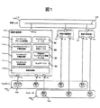
図1は、本発明による情報中継装置の一実施例を有する情報ネットワーク構成概念図である。情報中継装置とは、LANスイッチ等の論理的に構成されるネットワークを接続するネットワーク間接続機器である。
【0021】
図1に示す情報ネットワークは、複数のVLAN102(VLAN−A(102―1)、VLAN−B(102―2)、学習VLAN(102―3))と、複数のVLAN102間における情報中継動作を行う複数の情報中継装置101(情報中継装置1、情報中継装置2、情報中継装置3)と、複数の情報中継装置101間をつなぐネットワーク105と、VLAN―A(102―1)に接続されたマルチキャストサーバ103と、VLAN−A(102―1)に接続されたホスト等の端末104(端末A1、端末A2、端末A3)、VLAN−B(102―2)に接続されたホスト等の端末104(端末B1、端末B2、端末B3)とで構成されている。
【0022】
本実施形態の場合、個々の情報中継装置101は、通信処理部110と、マルチキャスト受信処理部111と、マルチキャスト中継処理部112と、マルチキャストアドレス学習処理部113と、マルチキャストプロトコル処理部114と、複数のポート115と、VLANテーブル20と、学習済みマルチキャスト情報テーブル50と、マルチキャスト学習テーブル40と、マルチキャストテーブル30とを有する。
【0023】
通信処理部110は、情報中継装置101に設けられる複数のポート115(ポート1〜10)を介して、外部の端末等との間で行なわれる情報の授受を制御する。通信処理部110は、ハードウェアまたはソフトウェア等で構成される。
【0024】
マルチキャスト受信処理部111は、後述する図9のフローチャートに示すように、マルチキャストパケットの種別に応じて、マルチキャストパケットの処理を、マルチキャスト中継処理、またはマルチキャストプロトコル処理のいずれかに振り分ける動作を行う。マルチキャスト受信処理部111は、ソフトウェア等で構成される。
【0025】
マルチキャスト中継処理部112は、後述の図10のフローチャートに示すように、受信したマルチキャストパケットを所定の送信先に送り出す動作を行うほか、マルチキャストアドレス学習処理への振り分け等を行う。マルチキャスト中継処理部112は、ソフトウェア等で構成される。
【0026】
マルチキャストアドレス学習処理部113は、マルチキャスト中継処理部112における送信先等をもとに、マルチキャスト学習テーブルを作成する動作を行う。マルチキャストアドレス学習処理部113は、ソフトウェア等で構成される。
【0027】
マルチキャストプロトコル処理部114は、例えば、IPマルチキャストやVLAN内におけるマルチキャスト等のマルチキャストパケットの制御プロトコル用メッセージの処理を行う。マルチキャストプロトコル処理部114は、ソフトウェア等で構成される。
【0028】
図1のVLANテーブル20の詳細を図2のVLANテーブル20に示す。VLANテーブル20において、VLAN−ID21と、ポートリスト22と、学習有効ポートリスト23とは、それぞれ対応付けられて登録される。情報中継装置101は、各ポート115を介して他の情報中継装置101または端末104と接続される。VLAN−ID21は、各々の情報中継装置101との間に存在する学習VLAN102−3、またはこの端末104が属するVLAN102のID識別子である。ポートリスト22は、各VLAN−ID21に対応して設けられており、他の情報中継処理101またはVLAN102内の端末104と接続されるポート115のリストである。学習有効ポートリスト23は、ポートリスト22に記録されるポート115が、学習処理の有効なポートであるか、あるいは無効なポートであるかを表す。
【0029】
本発明における学習とは、それぞれの情報中継装置101がマルチキャストパケットを受信した場合に、自装置が送信するべき全ての中継先をマルチキャスト学習テーブル40に記録することである。新たに構築されたVLANにおいて、最初にマルチキャストパケットを受信した後の所定の時間が経過して、学習処理が完了した後には、同一の宛先へ向けての同一のマルチキャストパケットは、物理的には同一の情報中継装置101であるが論理的に異なるネットワークに含まれる情報中継装置101を、複数回中継されることがなくなる。
【0030】
また、自情報中継装置101、および自情報中継装置101と接続する他の情報中継装置101がともに学習機能を有していれば、学習は有効である。これに対して、自情報中継装置101、または自情報中継装置101と接続する他の情報中継装置101の少なくとも一方が学習機能を有していなければ、学習は無効である。尚、学習の有効であるか、または無効であるかは、ネットワークが構成された後に、それぞれの情報中継装置が、お互いに通信することにより自動的に設定される。この通信は、専用のパケット、またはパケットヘッダ等に特定の情報を追加すること等により行われることが好ましい。また、学習の有効または無効を示す情報の設定は、手動で行われるものであってもかまわない。
【0031】
学習VLAN102−3は、自情報中継装置101および自情報中継装置101と接続される他の情報中継装置101がともに学習機能を有する場合に設定されるものである。学習VLAN102−3は、例えば、自情報中継装置101および自情報中継装置101に接続される他の情報中継装置101および自情報中継装置101と他の情報中継装置101との間の伝送媒体によって構成されるネットワークである。
【0032】
学習VLAN102−3のVLAN−ID21は、予め割り当てることがこのましい。しかし、予め割り当てる場合に限らず、VLAN−ID21が未指定の場合を学習VLAN102−3のVLAN−ID21とみなすよう設定することもよい。マルチキャストパケットを受信した情報中継装置101は、学習VLAN102−3のVLAN−ID21をもとに、受信したマルチキャストパケットを学習VLAN102−3から受信したものと認識する。また、マルチキャストパケットを学習VLAN102−3に送信するときは、学習VLAN102−3のVLAN−ID21宛てにマルチキャストパケットを送信する。
【0033】
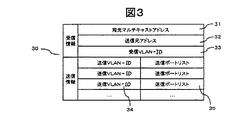
図1のマルチキャストテーブル30の詳細を、図3のマルチキャストテーブル30に示す。マルチキャストテーブル30は、受信情報と送信情報に分類された情報をそれぞれ1要素として対応付けられた各エントリにより構成される。
【0034】
受信情報として、宛先マルチキャストアドレス31と、送信元アドレス32と、受信VLAN−ID33とが登録される。宛先マルチキャストアドレス31は、マルチキャストパケットの宛先アドレスである。送信元アドレス32は、マルチキャストパケットの送信元アドレスである。受信VLAN−ID33は、情報中継装置101がマルチキャストパケットを受信したVLANのVLAN−ID21であり、情報中継装置101が受信したマルチキャストパケットの送信元方向のVLANのVLAN−ID21である。送信元アドレス32および受信VLAN−ID33を設けたのは、情報中継装置101がルータで構築されているネットワーク環境へ容易に導入することができることを目的とするためである。ルータでは、経路情報作成に際して送信元アドレス32および受信VLAN−ID33を必要とするアルゴリズムが普及している。なお、ルータは、第3層(ネットワーク層)以上のレベルで動作し、異なるネットワークの相互接続を行う。
【0035】
受信情報に対応する送信情報として、送信VLAN−ID34と、送信ポートリスト35とが対応付けられて登録されている。送信VLAN−ID34は、受信情報に対応するマルチキャストパケットの送信先VLANのVLAN−ID21であり、送信先のVLAN数分だけ設けられる。送信ポートリスト35は、送信VLAN−ID34に対応して設けられており、送信先であるVLAN102との間の情報中継装置101またはVLAN102内の端末104と接続するポート115のリストである。
【0036】
送信元アドレス32は、マルチキャストプロトコル処理部114と対応するプロトコルにより、必要な場合と必要でない場合とがある。また、図3に示すマルチキャストテーブル30は、VLAN間の情報中継処理とVLAN内の情報中継処理の双方に用いられる。
【0037】
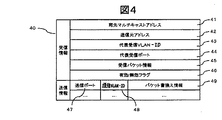
図1のマルチキャスト学習テーブル40の詳細を図4のマルチキャスト学習テーブル40に示す。マルチキャスト学習テーブル40は、最初にマルチキャストパケットを受信した時点から学習処理が完了するまでの時間に中継したマルチキャストパケットの学習結果を記録するテーブルである。マルチキャスト学習テーブル40は、受信情報と送信情報に分類された情報をそれぞれ1要素として対応付けられたエントリにより構成される。
【0038】
受信情報として、宛先マルチキャストアドレス41、送信元アドレス42、代表受信VLAN−ID43、代表受信ポート44、受信パケット情報45、有効/無効フラグ46が登録される。宛先マルチキャストアドレス41は、マルチキャストパケットの宛先アドレスである。送信元アドレス42は、マルチキャストパケットの送信元アドレスである。代表受信VLAN−ID43は、マルチキャストパケットの受信元のVLANのVLAN−ID21を表す。代表受信ポート44は、マルチキャストパケットを受信したポートを表す学習結果である。受信パケット情報45は、書換えられる前の、マルチキャストパケットの有する情報を表す。有効/無効フラグ46は、マルチキャスト学習テーブル40の登録が有効であるか無効であるかを示すものである。有効/無効フラグ46は、情報中継装置101が論理的に構成されたネットワークに接続された後所定の時間が経過したことを契機に、無効から有効へ自動的に切り替わる。この所定の時間とは、好ましくは、最初にマルチキャストパケットを受信した時点から学習処理が完了するまでの時間である。また、既に、送信済みのマルチキャストパケットと、宛先マルチキャストアドレス41および送信元アドレス42が同一であるパケットを、同一の代表受信ポート44から受信した場合は、有効であれば無効へ切り替わり、無効であれば無効の状態を維持する。
【0039】
送信情報は、受信情報に対応して設けられて、マルチキャストパケットの送信に際して用いられる。送信情報では、送信ポート47、送信VLAN−ID48、パケット書換え情報49が対応付けられて登録される。送信ポート47は、マルチキャストパケットが送信されるポート115である。送信ポート47のエントリ数は、{(ポート数)−1}である。{(ポート数)−1}は、自情報中継装置101が有するポート115の数からマルチキャストパケットの受信ポート数である1を引いた分を意味する。送信VLAN−ID48は、受信情報に対応するマルチキャストパケットの送信先VLANのVLAN−ID21である。パケット書換え情報49は、マルチキャストパケットの書換えに用いられる情報である。
【0040】
送信元アドレス42は、マルチキャストテーブル30と同様、マルチキャストプロトコル処理部114と対応するプロトコルにより、必要な場合と必要でない場合とがある。また、図4に示すマルチキャスト学習テーブル40は、図3に示すマルチキャストテーブル30と同様、VLAN間の情報中継処理とVLAN内の情報中継処理の双方に用いられる。
【0041】
学習処理が完了した場合は、マルチキャスト学習テーブル40を用いてマルチキャストパケットを中継することにより、本発明の効果を達成することが可能となる。すなわち、マルチキャストパケットを中継する際、情報中継装置101は、マルチキャスト学習テーブル40の受信情報に含まれる宛先マルチキャストアドレス41、送信元アドレス42、代表受信VLAN−ID43、代表受信ポート44、受信パケット情報45のそれぞれが受信したマルチキャストパケットの宛先アドレス、送信元アドレス、受信VLANのVLAN−ID21、受信ポートのそれぞれに全て該当する場合に、本テーブルの送信情報に含まれる全ての送信先(送信ポート47)にマルチキャストパケットを送信する。これにより、同一のマルチキャストパケットが物理的に同じ中継装置を複数回往復すること、または複製された同一のマルチキャストパケットが物理的に同じ中継装置を複数回通過することをなくして、必要以上のトラフィックの発生を防ぐことができる。
【0042】
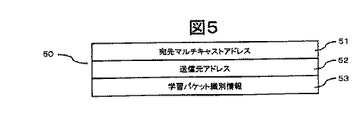
情報中継装置101は、最初にマルチキャストパケットを受信した後学習処理が完了するまでの間、マルチキャストパケットを受信する毎に、マルチキャストパケットに関する情報を学習済みマルチキャスト情報テーブル50に登録する。
【0043】
学習済みマルチキャスト情報テーブル50においては、図5に示すように、宛先マルチキャストアドレス51、送信元アドレス52、学習パケット識別情報53が対応付けられて登録されている。宛先マルチキャストアドレス51は、マルチキャスト学習処理によって学習済みのマルチキャストパケットの宛先アドレスである。送信元アドレス52は、マルチキャスト学習処理によって学習済みのマルチキャストパケットの送信元アドレスである。宛先マルチキャストアドレス51および送信元アドレス52は、マルチキャストテーブル30、マルチキャスト学習テーブル40のそれらと対応させるために設けられる。学習パケット識別情報53には、学習済みのマルチキャストパケットに関する情報が登録される。学習パケット識別情報53は、マルチキャスト学習テーブル40の有効/無効フラグ46が無効である場合に、マルチキャスト学習テーブル40に登録された学習済みのマルチキャストパケットと、宛先マルチキャストアドレス41および送信元アドレス42が同一であるマルチキャストパケットを受信すると、登録が追加される。この学習パケット識別情報53より、情報中継装置101が受信したマルチキャストパケットが、既に学習済みであるか否かが識別される。
【0044】
送信元アドレス52はマルチキャストテーブル30と同様、マルチキャストプロトコル処理部114と対応するプロトコルにより、必要な場合と必要でない場合とがある。
【0045】
以下、マルチキャストパケットの中継処理について説明する。
【0046】
以下の説明では、情報中継装置101のマルチキャスト学習処理の一例として、TCP/IPにおけるマルチキャストプロトコルであるIPマルチキャストの学習処理について説明する。このTCP/IPには、IPv4(Internet Protocol version 4)やIPv6(Internet Protocol version 6)等の異なるバージョンのプロトコルが存在する。しかし、以下の説明においては、これらのバージョン毎のIPv4マルチキャストやIPv6マルチキャスト等を区別せずにIPマルチキャストと表記する。そして、特に指定のない場合は、いずれのプロトコルにおいても同様の動作を行うものとする。
【0047】
IPマルチキャストに関しては、マルチキャストテーブル30、マルチキャスト学習テーブル40、学習済みマルチキャスト情報テーブル50のそれぞれに対応するものが、IPマルチキャストテーブル60(図6)、IPマルチキャスト学習テーブル70(図7)、学習済みIPマルチキャスト情報テーブル80(図8)である。
【0048】
IPマルチキャストテーブル60においては、図6に示すように、マルチキャストテーブル30の宛先マルチキャストアドレス31、送信元アドレス32のそれぞれに対応するものが、宛先IPマルチキャストアドレス61、送信元IPアドレス62である。その他に関してはマルチキャストテーブル30と同様にして、受信VLAN−ID63、複数の送信VLAN−ID64、送信ポートリスト65が登録される。
【0049】
IPマルチキャスト学習テーブル70においては、図7に示すように、マルチキャスト学習テーブル40の宛先マルチキャストアドレス41、送信元アドレス42、受信パケット情報45のそれぞれに対応するものが、宛先IPマルチキャストアドレス701、送信元IPアドレス702、学習パケットTTL705である。学習パケットTTL705には、IPヘッダにおける中継限界数を示す値、例えば、IPv4ヘッダにおけるTTL、またはIPv6ヘッダにおけるHop Limitの値を登録する。以下、IPヘッダにおける中継限界数を示す領域をTTLと既述し、IPv4ヘッダの場合はTTL値を、IPv6ヘッダの場合はHop Limit値を表すものとする。
【0050】
また、パケット書換え情報49に対応するものは、TTL減算数709および送信元第2層アドレス710である。TTL減算数709は、IPヘッダのTTL領域の書換えに使用するものであり、書換え後のTTLから書換え前のTTLを減じた値である。受信したマルチキャストパケットのTTLの値から、TTL減算数709分を減じた後、そのマルチキャストパケットを中継することにより、ネットワークのトラヒックを削減する目的がある。送信元第2層アドレス710は、OSI参照モデルの第2層(データリンク層)におけるアドレスでありIPマルチキャストのIPマルチキャストパケットの中継処理に際して書き換えられる送信もとのアドレスである。この第2層におけるアドレスとは、例えば、Ethernet(EthernetはXerox社の登録商標)におけるMAC(Media Access Control)アドレス等である。なお、IPマルチキャストは、第2層(データリンク層)のプロトコルには依存しない。その他に関してはマルチキャスト学習テーブル40と同様に、代表受信VLAN−ID703、代表受信ポート704、有効/無効フラグ706、複数の送信ポート707、送信VLAN−ID708が登録される。
【0051】
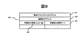
学習済みIPマルチキャスト情報テーブル80は、図8に示すように、学習済みマルチキャスト情報テーブル50における宛先マルチキャストアドレス51には宛先IPマルチキャストアドレス81が、送信元アドレス52には送信元IPアドレス82が、学習パケット識別情報53には、受信VLAN83と、学習済み受信ポート84とがそれぞれ対応付けられて登録される。受信VLAN83と、学習済み受信ポート84とは、一つの宛先IPマルチキャストアドレス81、送信元IPアドレス82当たり、複数設けられる。学習済み受信VLAN−ID83は、IPマルチキャスト学習テーブル70の有効/無効フラグ706が無効である場合に、IPマルチキャスト学習テーブル70に登録された学習済みのマルチキャストパケットと、宛先IPマルチキャストアドレス81および送信元IPアドレス82が同一であるマルチキャストパケットを受信したVLANのVLAN−ID21である。学習済み受信ポート84は、学習済み受信VLANからマルチキャストパケットを受信したポートである。
【0052】
以下、情報中継装置101の動作の一例について説明する。
【0053】
はじめに、図9のフローチャートを用いてマルチキャスト受信処理部111の動作を説明する。
【0054】
受信したパケットが、マルチキャストパケットであるか否かを判断して(ステップ91)、マルチキャストパケットである場合には、それがマルチキャストプロトコルパケットであるか否かを判断する(ステップ92)。マルチキャストパケットでない場合には、通常のパケットの中継処理を行う。マルチキャストプロトコルパケットとは、マルチキャストパケットの制御プロトコル用パケットである。この制御プロトコルには、例えば、図1において、VLAN−AからVLAN−Bへの中継を行うテーブルを、どの情報中継装置101に設けるかを決定させるプロトコル等がある。この制御プロトコルにより、マルチキャスト中継処理が行われる。なお、マルチキャストプロトコルパケットは、当然に学習対象ではない。
【0055】
マルチキャストパケットが、マルチキャストプロトコルパケットである場合には、所定のマルチキャストプロトコル処理を行う(ステップ94)。マルチキャストプロトコルパケットでない場合には、マルチキャスト中継処理部112において、後述の図10のフローチャート等に示すマルチキャスト中継処理(ステップ93)を行う。
【0056】
次に、この(ステップ93)で行なわれるマルチキャスト中継処理について説明する。
【0057】
マルチキャスト中継処理の一例を図10のフローチャートに示す。このマルチキャスト中継処理は、マルチキャスト中継処理部112が行う。
【0058】
受信したマルチキャストパケットの宛先IPマルチキャストアドレス61、送信元IPアドレス62、受信VLAN−ID63をもとに、IPマルチキャストテーブル60を検索する(ステップ1001)。
【0059】
IPマルチキャストテーブル60の検索がヒットしなかった場合は(ステップ1002)、自情報中継装置101が中継処理する必要のないマルチキャストパケットであるから、このマルチキャストパケットを廃棄する(ステップ1003)。
【0060】
検索がヒットした場合には(ステップ1002)、IPマルチキャスト学習テーブル70の検索を行う(ステップ1004)。この検索では、受信したマルチキャストパケットの宛先マルチキャストアドレス、送信元アドレスをもとに、IPマルチキャスト学習テーブル70の宛先IPマルチキャストアドレス701、送信元IPアドレス702を検索する。
【0061】
IPマルチキャスト学習テーブル70の検索でヒットしなかった場合(ステップ1005)、IPマルチキャスト学習テーブル70の新規エントリの作成と受信情報の登録処理を行う(ステップ1006)。この処理を行う理由は、受信したマルチキャストパケットと、宛先IPマルチキャストアドレス701および送信元IPアドレス702が同一であるマルチキャストパケットが、未学習であるからである。IPマルチキャスト学習テーブル70に新規エントリを作成し、その新規エントリに受信したマルチキャストパケットの宛先マルチキャストアドレス、送信元アドレスを登録する。代表受信ポート704に受信したポートを登録する。代表受信VLAN−ID703には、受信したポートが学習の有効なポートであれば学習VLANのVLAN−ID21を、学習の無効なポートであれば受信したVLANのVLAN−IDを登録する。学習パケットTTL705には、受信したマルチキャストパケットのIPヘッダ内のTTL値を登録する。
【0062】
次に、学習済みIPマルチキャスト情報テーブル80の新規エントリの作成を行う(ステップ1007)。学習済みIPマルチキャスト情報テーブル80に新規エントリを作成する。その新規エントリの宛先IPマルチキャストアドレス81、送信元IPアドレス82、学習済み受信VLAN−ID83、学習済み受信ポート84に、受信したマルチキャストパケットの宛先マルチキャストアドレス、送信元アドレス、受信したVLANのVLAN−ID21、受信したポートをそれぞれ登録する。
【0063】
次に、後述する図13のフローチャートに示すIPマルチキャスト学習テーブル70の送信情報更新処理(ステップ1008)を行う。この後、新規に作成したIPマルチキャスト学習テーブル70の有効/無効フラグ706を無効に設定し、タイマをセットする(ステップ1009)。このタイマは、所定の時間経過後に、この有効/無効フラグ706を有効に変更する機能を有する。従って、所定の時間経過後に、新規に作成されたIPマルチキャスト学習テーブル70のエントリが有効になる。
【0064】
最後に、後述する図12のフローチャートに示す未学習マルチキャストの中継処理によって、マルチキャストパケットの中継処理を行う(ステップ1010)。
【0065】
なお、IPマルチキャスト学習テーブル70の新規エントリの作成と受信情報の登録処理(ステップ1006)と、学習済みIPマルチキャスト情報テーブル80の新規エントリの作成(ステップ1007)との処理は、互いの処理の順序を入れ換えることも好ましい。
【0066】
一方、IPマルチキャスト学習テーブル70の検索でヒットし(ステップ1005)、かつ、ヒットしたテーブルエントリの有効/無効フラグ706が無効である場合(ステップ1011)、学習済みIPマルチキャスト情報テーブル80の検索を行う(ステップ1012)。この場合、有効/無効フラグ706が無効であるから、IPマルチキャスト学習テーブル70への学習は完了していないこととなる。(ステップ1012)においては、受信したマルチキャストパケットの宛先マルチキャストアドレス、送信元アドレスと一致する宛先IPマルチキャストアドレス81、送信元IPアドレス82を有する学習済みIPマルチキャスト情報テーブル80が検索される。マルチキャストパケットの受信VLANのVLAN−ID21、受信ポートのそれぞれが、この学習済みIPマルチキャスト情報テーブル80に登録されている学習済み受信VLAN−ID83、学習済み受信ポート84と一致するか否かが検索される。
【0067】
学習済みIPマルチキャスト情報テーブル80の検索(ステップ1012)の結果、受信VLANのVLAN−ID21、受信ポートが、ともに対応して、学習済み受信VLAN−ID83、学習済み受信ポート84として登録されていない場合には、学習が必要と判断して(ステップ1013)、後述する図11のフローチャートに示すマルチキャスト学習テーブルの受信情報更新処理を行う(ステップ1014)。
【0068】
さらに、受信したマルチキャストパケットの宛先マルチキャストアドレス、送信元アドレスに対応する学習済みIPマルチキャスト情報テーブル80のエントリに、受信したマルチキャストパケットの受信VLANと受信ポートを対応させて追加登録する(ステップ1015)。
【0069】
その後、上述した(ステップ1008)、(ステップ1009)、(ステップ1010)の処理を行う。なお、マルチキャスト学習テーブルの受信情報更新処理(ステップ1014)と、学習済みIPマルチキャスト情報テーブル80のエントリへの追加登録(ステップ1015)との処理は、互いの処理の順序を入れ換えることも好ましい。
【0070】
また、学習済みIPマルチキャスト情報テーブル80の検索(ステップ1012)の結果、受信VLANのVLAN−ID21、受信ポートが、ともに対応して、学習済み受信VLAN−ID83、学習済み受信ポート84として登録されている場合(ステップ1013)、学習が不要と判断して、未学習マルチキャストの中継処理(ステップ1010)のみを行う。この場合に学習を不要とする理由は、既に、受信したマルチキャストパケットと、宛先IPマルチキャストアドレス701および送信元IPアドレス702が同一であるマルチキャストパケットを同一の代表受信ポート704から受信し、同一の経路で中継済みだからである。
【0071】
他方、IPマルチキャスト学習テーブル70の有効/無効フラグ706が有効である場合(ステップ1011)を説明する。この場合、学習が完了している。受信したマルチキャストパケットの受信VLANのVLAN−ID21および受信ポートが、IPマルチキャスト学習テーブル70に登録されている代表受信VLAN−ID703および代表受信ポート704とそれぞれ一致している場合には(ステップ1017)、IPマルチキャスト学習テーブル70のエントリを用い、後述する図14に示す学習済みマルチキャストの中継処理を行う(ステップ1016)。
【0072】
受信したマルチキャストパケットの受信VLANのVLAN−ID21および受信ポートが、IPマルチキャスト学習テーブル70に登録されている代表受信VLAN−ID703および代表受信ポート704と一致しない場合(ステップ1017)には、受信したマルチキャストパケットを廃棄する(ステップ1003)。既に学習が完了しているため、IPマルチキャスト学習テーブル70に登録されていない受信VLANまたは受信ボートから受信したマルチキャストパケットは、中継する必要のないマルチキャストパケットとなる。
【0073】
以上が図9の(ステップ93)におけるマルチキャスト中継処理の一例である。
【0074】
次に、図10の(ステップ1014)におけるマルチキャスト学習テーブルの受信情報更新処理を、図11のフローチャートを用いて説明する。
【0075】
まず、受信したマルチキャストパケットのIPヘッダのTTL値と、IPマルチキャスト学習テーブル70に登録済みの学習パケットTTL705とを比較する(ステップ1101)。
【0076】
受信したマルチキャストパケットのTTL値が、学習パケットTTL705の値以下の場合には、特別な処理を行わず、図10に示す(ステップ1015)へ移行することとする。
【0077】
受信したマルチキャストパケットのTTL値が、学習パケットTTL705の値よりも大きい場合には、受信したマルチキャストパケットのTTL値を、IPマルチキャスト学習テーブル70の学習パケットTTL705として、従前の学習パケットTTL705の値と変更して登録する。さらに、受信したマルチキャストパケットの受信ポートを、代表受信ポート704として登録する(ステップ1102)。
【0078】
次に、VLANテーブル20を検索する(ステップ1103)。この検索により、受信したマルチキャストパケットの受信VLANに対応する受信ポートが、学習の無効なポートである場合には(ステップ1104)、IPマルチキャスト学習テーブル70の代表受信VLAN−ID703に、受信したマルチキャストパケットの受信VLANのVLAN−ID21を登録する(ステップ1105)。受信したマルチキャストパケットの受信VLANに対応する受信ポートが、学習の有効なポートである場合には(ステップ1104)、IPマルチキャスト学習テーブル70の代表受信VLAN−ID703に、学習VLANのVLAN−ID21を登録する(ステップ1106)。
【0079】
最後に、IPマルチキャスト学習テーブル70の送信情報として登録済みのTTL減算数709を、受信したマルチキャストパケットのTTL値と従前の学習パケットTTL705の値との差と、従前の学習パケットTTL705の値を加えた値に変更する(ステップ1107)。
【0080】
以上が図10の(ステップ1014)におけるIPマルチキャスト学習テーブル70の受信情報更新処理の一例である。
【0081】
次に、図10のステップ1010における未学習マルチキャストの中継処理を、図12のフローチャートを用いて説明する。
【0082】
まず、図10の(ステップ1001)によるIPマルチキャストテーブル60の検索結果に従い、IPマルチキャストテーブル60の送信情報に登録されている送信VLAN、送信ポートの全てに対して以下の処理を行う(ステップ1201)。
【0083】
受信したマルチキャストパケットの受信VLANと、これから送信するVLANが異なる場合(ステップ1202)、マルチキャストパケットのIPヘッダ内のTTLの値を1だけ減算{(TTLの値)−1}する(ステップ1203)。減算後のTTLの値が、0より大きい{TTL>0}ならば(ステップ1204)、TTL減算に伴うIPヘッダのチェックサム計算を行う。また、マルチキャストパケットの送信元第2層(データリンク層)アドレスを、送信するVLANに対応するアドレスに変更する(ステップ1205)。チェックサム計算とは、例えば、エラーチェック等のことである。なお、チェックサム計算はIPv4マルチキャストの場合に行われるものであり、IPv6マルチキャストにおいてはチェックサム計算の処理の必要はない(以下、チェックサム計算に関してはIPv4マルチキャストにおいてのみ行われるものとする)。
【0084】
(ステップ1205)の後、パケット送信処理(ステップ1206)を行う。パケット送信処理とは、情報中継装置101に設けられる通信処理部110が、所定の送信ポートを介して所定の送信VLAN宛にマルチキャストパケットを送出する処理である。
【0085】
一方、受信したマルチキャストパケットの受信VLANと、送信するVLANが同一である場合(ステップ1202)、同一VLAN内のマルチキャストパケットの中継であるので、TTLの値を減算させないこととする。これは、従来、異なるセグメント間を接続するルータが、同一セグメントに属するホストどうしのパケットの送受信においてはTTLを減算しないことと統一させることを目的としたことに伴う。従って、この場合、上述した(ステップ1203)、(ステップ1204)、(ステップ1205)の処理は行わず、パケット送信処理(ステップ1206)を行う。
【0086】
他方、(ステップ1204)において{TTL>0}ではない場合、上述した(ステップ1205)、(ステップ1206)の処理は行わず、中継処理を終了する。
【0087】
以上が図10の(ステップ1010)における未学習マルチキャストの中継処理の一例である。
【0088】
次に、図10の(ステップ1008)におけるIPマルチキャスト学習テーブル70の送信情報更新処理を、図13のフローチャートを用いて説明する。
【0089】
まず、図10の(ステップ1001)におけるIPマルチキャストテーブル60の検索結果に従い、IPマルチキャストテーブル60に登録されている送信ポート、送信VLANの全てに対して以下の処理を行う(ステップ1301)。
【0090】
まず、VLANテーブル20を検索し、送信VLANに対応する送信ポートが学習の無効なポートである場合(ステップ1302)について説明する。(ステップ1006)により受信情報の登録処理、または(ステップ1014)により受信情報の更新処理を行ったIPマルチキャスト学習テーブル70の送信情報に、新規に、送信ポート707、送信VLAN−ID708、TTL減算数709、送信元第2層(データリンク層)アドレス710のそれぞれのエントリ領域を作成して、登録する(ステップ1303)。送信ポート707、送信VLAN−ID708には、IPマルチキャストテーブル60の検索結果より得られる送信ポート、送信VLANのVLAN−ID21を登録する。TTL減算数709には、受信したマルチキャストパケットのTTLの値と、IPマルチキャスト学習テーブル70の学習パケットTTL705の値との差{(受信したマルチキャストパケットのTTLの値)−(学習パケットTTL705の値)}を計算して登録する。ただし、TTL減算数709は、マルチキャストパケットの受信VLANと送信VLANが異なる場合には、さらに1だけ減算した値{(受信したマルチキャストパケットのTTLの値)−(学習パケットTTL705の値)−1}を登録する。以下、このようにして得られた値のことを、受信パケットのTTL減算数と表記する。送信元第2層(データリンク層)アドレス710には、送信VLANに対応する送信元第2層(データリンク層)アドレスを登録する。
【0091】
次に、VLANテーブル20を検索し、送信VLANに対応する送信ポートが学習の有効なポートである場合(ステップ1302)について説明する。検索結果の送信ポートと、IPマルチキャスト学習テーブル70の代表受信ポート704とが一致し、かつ、代表受信VLAN−ID703が学習VLANのVLAN−ID21である場合(ステップ1304)には、以下の処理を行わずに、IPマルチキャスト学習テーブル70の送信情報更新処理を終了する。この場合、代表受信VLAN−ID703が学習VLANのVLAN−ID21であることより、自情報中継装置101は、学習機能を有している他情報中継装置101と接続していることになる。従って、送信ポートと代表受信ポート704とが一致している場合、自情報中継装置101は、他情報中継装置101への送信の必要はなく、以下の処理を行う必要もない。なお、代表受信VLAN−ID703が学習VLANのVLAN−ID21ではない場合には、自中継装置101には、端末104、または、学習機能を有していない他情報中継装置のいずれかが接続していることとなる。
【0092】
一方、送信ポートと代表受信ポート704とが一致しない、または、代表受信VLAN−ID703が学習VLANのVLAN−ID21ではない場合(ステップ1304)には、IPマルチキャスト学習テーブル70の送信情報において、マルチキャストパケットの送信ポートと同一の送信ポート707に対応する送信VLAN−ID708が、学習VLANのVLAN−ID21での登録か否かの判断を行う(ステップ1305)。この送信VLAN−ID708が、学習VLANのVLAN−ID21でない場合(ステップ1305)には、新規に、送信ポート707、送信VLAN−ID708、TTL減算数709、送信元第2層アドレス710のそれぞれのエントリ領域を作成し、登録する(ステップ1306)。送信ポート707には、IPマルチキャストテーブル60の検索結果より得られる送信ポートを登録する。送信VLAN−ID708には、学習VLANのVLAN−ID21を登録する。TTL減算数には、受信パケットのTTL減算数を登録する。送信元第2層アドレス710には、学習VLANに対応する送信元第2層アドレスを登録する。ここで、IPマルチキャスト学習テーブル70の送信情報の新規エントリに、送信VLAN−ID708を学習VLANのVLAN−ID21として登録を追加する理由は、自情報中継装置101が、Ethernet、レイヤ2スイッチ等の第3層(ネットワーク層)以上のレベルで動作する機能を持たないものを介して、学習機能を有する他情報中継装置101と接続している場合を考慮したためである。
【0093】
他方、マルチキャストパケットの送信ポートと同一の送信ポート707に対応する送信VLAN−ID708が、学習VLANのVLAN−ID21である場合(ステップ1305)、IPマルチキャスト学習テーブル70に登録済みのTTL減算数709と、受信パケットのTTL減算数とを比較する。登録済みのTTL減算数709が、受信パケットのTTL減算数より大きい場合には(ステップ1307)、登録済みの送信ポート707、送信VLAN−ID708、TTL減算数709、送信元第2層アドレス710をそれぞれ更新する(ステップ1308)。この更新により、TTL減算数709は、受信パケットのTTL減算数となり、他の送信情報は、更新前と同様である。すなわち、送信ポート707は、IPマルチキャストテーブル60の検索結果より得られる送信ポートである。送信VLAN−ID708は、学習VLANのVLAN−ID21である。送信元第2層アドレス710は、学習VLANに対応する送信元第2層アドレスである。
【0094】
また、登録済みのTTL減算数709が、受信パケットのTTL減算数以下の場合(ステップ1307)には、(ステップ1308)の処理は行わずに、IPマルチキャスト学習テーブル70の送信情報更新処理を終了する。
【0095】
以上が図10の(ステップ1008)におけるIPマルチキャスト学習テーブル70の送信情報更新処理の概要である。
【0096】
次に、図10の(ステップ1016)における学習済みマルチキャストの中継処理の動作を、図14のフローチャートを用いて説明する。
【0097】
IPマルチキャスト学習テーブル70を検索して、送信情報として登録された送信ポート707の全てに対して以下の処理を行う(ステップ1401)。
【0098】
まず、送信ポートに対応して登録されたTTL減算数709に従い、マルチキャストパケットのIPヘッダのTTL値から、登録されたTTL減算数分を減算する(ステップ1402)。
【0099】
減算の結果、TTL>0であった場合(ステップ1403)、マルチキャストパケットのIPヘッダの送信元第2層アドレスを、送信ポートに対応する登録の送信元第2層アドレス710に付け替える。また、TTL減算に伴うチェックサムの再計算を行う(ステップ1404)。その後、通信処理部110が、マルチキャストパケットを情報中継装置101から登録された送信VLAN708宛に送信ポートを介して送信する(ステップ1405)。
【0100】
ステップ1403でTTL>0でなかった場合、(ステップ1404)、(ステップ1405)の処理は行わない。
【0101】
以上が図10の(ステップ1016)における学習済みマルチキャストの中継処理の一例である。
【0102】
次に、以上で説明した情報中継装置を用いて情報ネットワークを構成する。この情報ネットワークを用いて、IPマルチキャスト通信の一例を示す。
【0103】
図15は、図1の情報ネットワークにおけるIPマルチキャスト通信のパケットフローの一例である。図1の情報ネットワークにおいて、マルチキャストサーバ103はVLAN−A(102−1)に属する。VLAN−A(102−1)に属する端末104(端末A1、端末A2、端末A3)およびVLAN−B(102−2)に属する端末104(端末B1、端末B2、端末B3)は、それぞれマルチキャストサーバ103の送信するIPマルチキャストデータの宛先であるIPマルチキャストグループメンバーに加入しているものとする。また、ポート4、ポート7、ポート10はVLAN−A、VLAN−B双方に属し、それぞれで学習の有効なポートであるとする。各情報中継装置101の持つIPマルチキャストテーブル60のうち、VLAN−A(102−1)からVLAN−B(102−2)への中継を行うIPマルチキャストテーブル60は、情報中継装置1が持つものとする。
【0104】
まず、マルチキャストサーバ103がマルチキャストデータ1501を送信する。情報中継装置1は、VLAN−A(102−1)から受信した新規のIPマルチキャストアドレスに対するIPマルチキャスト学習テーブル1230の新規エントリを作成し、受信情報を登録する(ステップ1006)。この際、受信したVLAN−A(102−1)における受信ポート1は学習の有効なポートではなく、代表受信VLAN−ID703としてはVLAN−A(102−1)のVLAN−ID21を登録する。
【0105】
次に、IPマルチキャストテーブル60の検索(ステップ1001)の結果により、まずVLAN−A(102−1)内における中継処理を行う。情報中継装置1から、VLAN−A(102−1)内に属する端末104および情報中継装置101の存在するポート3、ポート4に対して、IPマルチキャスト学習テーブル1230の送信情報の登録処理を行う(ステップ1008)。VLAN−A(102−1)に宛てて、ポート2からデータ1502を送信して、ポート4からデータ1503を送信する。この時、送信先であるVLAN−A(102−1)のポート4は学習が有効なポートであるため、送信VLAN−ID708を学習VLANのVLAN−ID21として登録する(ステップ1306)。また、VLAN−A(102−1)内における中継のため、送信元第2層アドレスの付替えは行わず、送信情報としてはマルチキャストパケットのIPヘッダ内の送信元第2層アドレスを登録する。
【0106】
続けてIPマルチキャストテーブル60の検索(ステップ1001)の結果に従い、VLAN−A(102−1)からVLAN−B(102−2)への中継処理を行う。VLAN−B(102−2)内に属する端末および情報中継装置の存在するポート3、ポート4に対してIPマルチキャスト学習テーブル1230の送信情報の登録処理を行う(ステップ1008)。VLAN−Bに宛て、ポート3からデータ1506を送信し、ポート4からデータ1507を送信する。この時、ポート3は新規送信先であり、送信情報の登録を行う(ステップ1008)。VLAN−A(102−1)からVLAN−B(102−2)への中継においては、送信元第2層アドレスを情報中継装置1におけるVLAN−B(102−2)に対応する第2層アドレスに付け替え、送信情報として付け替える送信元第2層アドレス710を登録する。
【0107】
ポート4はVLAN−A宛の中継に際し、学習処理(ステップ1006、1007、1008、1009)において既に送信情報を登録済みである(ステップ1302)。ポート4は学習有効なポートでもあることから、送信VLAN−ID708を学習VLANのVLAN−ID21として送信情報が登録されている(ステップ1305)。この場合、送信情報のTTL減算数709を、よりTTL減算数の小さい送信情報に更新する(ステップ1307)。しかし、図15のパケットフローの例の場合には、VLAN−B宛送信においてはVLAN−Aから受信したパケットのTTLを1だけ減算(−1)する中継であり、VLAN−A宛の中継処理時に登録した送信情報のTTL減算数709よりもVLAN−B宛のTTL減算数が大きいことから、ポート4に関する送信情報は更新されない。
【0108】
最後に、タイマをセットする(ステップ1009)。このタイマにより、新規に作成したIPマルチキャスト学習テーブル70のエントリに対する有効/無効フラグ706は、所定の時間後に有効となる。
【0109】
情報中継装置2では、まず、情報中継装置1が送信したVLAN−A(102−1)宛のデータ1503を受信し、VLAN−A(102−1)から受信した新規のIPマルチキャストアドレスに対するIPマルチキャスト学習テーブル70の新規エントリを作成し、受信情報を登録する(ステップ1006)。この時、受信したVLAN−A(102−1)のポート7は学習が有効なポートであるため、代表受信VLAN−ID703として学習VLANのVLAN−ID21を登録する。
【0110】
次に、IPマルチキャストテーブル60の検索(ステップ1001)の結果により、VLAN−A(102−1)内の中継処理を行う。端末A2の存在するポート5に対して、送信情報を登録して(ステップ1008)、VLAN−A(102−1)宛のデータ1504を送信する。ポート5は学習が有効では無いため(1302)、送信情報の送信VLAN−ID708にはVLAN−AのVLAN−ID21を登録し(ステップ1303)、送信元第2層アドレス710は、VLAN−B内の中継のため、マルチキャストパケットのIPヘッダ内の内の第2層アドレスを登録する。また、有効/無効フラグ用のタイマをセットする(ステップ1009)。
【0111】
その後、情報中継装置1の送信したVLAN−B(102−2)宛のデータ1507を受信して、学習処理(ステップ1014、1015、1008、1009)を行う。この場合、データ1507と同一のデータを既にVLAN−A(102−1)から受信済みであり、受信情報更新処理を行う(ステップ1014)。IPマルチキャスト学習テーブル70の学習パケットTTL705より、受信したマルチキャストパケットのTTLの方が大きい場合(ステップ1101)、受信情報を更新する(ステップ1102)。しかし、図15のパケットフローの例の場合には、VLAN−A(102−1)宛のデータ1503のTTLの方が大きいため、IPマルチキャスト学習テーブル70の代表受信VLAN−ID703、代表受信ポート704、学習パケットTTL705の受信情報は更新されない。さらに、VLAN−B(102−2)内の中継処理を行い、端末B2の存在するポート6に対して、送信情報を登録する(ステップ1008)。VLAN−B(102−2)宛のデータ1508を中継する。ポート6は、学習が有効ではない(ステップ1302)。従って、送信情報の送信VLAN−ID708は、VLAN−B(102−2)のVLAN−ID21を登録する(ステップ1303)。VLAN−B(102−2)内の中継であるため、送信情報の送信元第2層アドレス710には、マルチキャストパケットのIPヘッダ内の第2層アドレスを登録する。また、有効/無効フラグ706用のタイマを再セットする(ステップ1009)。
【0112】
情報中継装置3における動作は情報中継装置2における動作と同様であり、学習処理を行い、ポート8からVLAN−A宛のデータ1505を送信し、ポート9からVLAN−B宛のデータ1509を送信する(ステップ1006、1007、1014、1015、1008、1009)。
【0113】
その後、各情報中継装置101におけるIPマルチキャスト学習テーブル70の有効/無効フラグ706が有効になった後に(ステップ1011)、マルチキャストサーバ103が同じ宛先のマルチキャストデータ1510を送信する。情報中継装置1は、IPマルチキャスト学習テーブル70を検索する(ステップ1004)。宛先IPマルチキャストアドレス701、代表受信VLAN−ID703、代表受信ポート704が一致するテーブルエントリがヒットする(ステップ1005)。その検索の結果に従い、登録されているポート2、ポート3、ポート4に対して、マルチキャストパケットを送信する(ステップ1405)。その際、TTLから登録されたTTL減算数709を減算し、登録された送信元第2層アドレス710に付け替える(ステップ1404)。ポート2およびポート3は学習が有効ではないため、それぞれのポートに対して、VLAN−A(102−1)宛データ1511、VLAN−B(102−2)宛データ1512を送信する。ポート4に対しては、学習VLAN(102−3)宛のデータ1513を送信する。
【0114】
情報中継装置2では、情報中継装置1が送信した学習VLAN(102−3)宛のデータ1513を受信し、IPマルチキャスト学習テーブル70を検索する(ステップ1004)。学習VLAN(102−3)宛のデータ1513に対応する宛先IPマルチキャストアドレスに対して、代表受信VLAN−ID703が学習VLANのVLAN−ID21であるテーブルエントリがヒットする(ステップ1005)。この検索の結果に従い、登録されたポート5、ポート6に対する中継処理を行う(ステップ1016)。ポート5からVLAN−A(102−1)宛のデータ1514を送信し、ポート6からVLAN−B(102−2)宛のデータ1515を送信する。
【0115】
情報中継装置3における動作は情報中継装置2における動作と同様であり、ポート8からVLAN−A(102−1)宛のデータ1516を送信し、ポート9からVLAN−B(102−2)宛のデータ1517を送信する(ステップ1016)。
【0116】
以上が、本発明である情報中継装置101による、IPマルチキャスト通信の一例である。
【0117】
図16に、IPv4マルチキャストにおいてのマルチキャストパケットのヘッダフォーマット1600の一例を示す。
【0118】
IPv4マルチキャストの場合、図5に示す学習済みマルチキャスト情報テーブル50における学習パケット識別情報53として、図16に示すIPヘッダ内のID1601を使用することも好ましい。この場合、学習済みマルチキャスト情報テーブル50に対応する学習済みIPv4マルチキャスト情報テーブル1700は、図17のように示される。宛先IPv4マルチキャストアドレス1701、送信元IPv4アドレス1702、学習パケットID1703が、それぞれ対応付けられて登録される。学習パケットID1703には、IPヘッダ内のID値を登録する。
【0119】
以下、学習済みIPv4マルチキャスト情報テーブル1700を用いた場合の動作の一例を説明する。
【0120】
学習済みIPv4マルチキャスト情報テーブル1700を用いる場合、図10に示すマルチキャスト中継処理の(ステップ1007)においては、新規作成する学習済みIPv4マルチキャスト情報テーブル1700のエントリに、受信したマルチキャストパケットのIPヘッダのID値を登録する。
【0121】
(ステップ1012)における学習済みIPv4マルチキャスト情報テーブル1700の検索においては、受信したマルチキャストパケットのIPヘッダ内のIDと、学習済みIPv4マルチキャスト情報テーブル1700の学習パケットID1703との値の比較を行う。
【0122】
(ステップ1013)においては、(ステップ1012)におけるIDの比較で一致した場合には、学習が必要であると判断して、(ステップ1014)へと処理を進める。また、(ステップ1012)において、IDが一致しなかった場合には、学習の必要はないと判断する。(ステップ1015)においては、受信したマルチキャストパケットと、学習パケットID1703との値は一致しているため、更新処理は行わない。
【0123】
以上が、図17に示す学習済みIPv4マルチキャスト情報テーブル1700を用いた場合における動作の一例である。
【0124】
図18は、本発明である情報中継装置101を用いて、他の情報ネットワークを構築した場合の一例である。
【0125】
図18の情報ネットワークでは、本発明である複数の情報中継装置1801(情報中継装置1、情報中継装置2、情報中継装置3)が、同じく本発明である情報中継装置1801(情報中継装置4)を介して接続されている。
【0126】
情報中継装置1には、マルチキャストサーバ1802、端末A1が接続する。マルチキャストサーバ1802は、VLAN−A(1810)に属する。端末A1も、VLAN−A(1810)に属しており、複数のマルチキャスト受信端末1803(端末A1、端末A2、端末B1、端末B2)のうちの1つである。情報中継装置2には、VLAN−A(1810)に属する端末A2、およびVLAN−Bに属する端末B1が接続する。情報中継装置3には、VLAN−B(1811)に属する端末B2が接続する。
【0127】
なお、端末A1、端末A2および端末B1、端末B2は、マルチキャストサーバ1802が送信するマルチキャストのグループメンバーに加入しているものとする。
【0128】
また、情報中継装置4と、情報中継装置4以外の各情報中継装置1801との間の接続のポート(ポート3、ポート6、ポート8、ポート9、ポート10、ポート11)は、VLAN−A(1810)およびVLAN−B(1811)に属しており、学習の有効なポートとして設定されているものとする。
【0129】
各情報中継装置1801の持つマルチキャストテーブル30のうち、VLAN−A(1810)からVLAN−B(1811)への中継を行うマルチキャストテーブル30は、情報中継装置2が持つものとする。
【0130】
図18の情報ネットワークにおけるIPマルチキャスト通信の一例を、図19に示するパケットフローを用いて説明する。
【0131】
まず、マルチキャストサーバ1802が、マルチキャストデータ1901を送信する。情報中継装置1は、ポート1を介して、マルチキャストパケットをVLAN−A(1810)から受信する。新規に受信したマルチキャストパケットの宛先IPマルチキャストアドレスに対して、IPマルチキャスト学習テーブル70の新規エントリを作成して、受信情報を登録する(ステップ1006)。この時、ポート1は学習が有効ではないので、代表受信VLAN−ID703にはVLAN−A(1810)のVLAN−ID21を登録する。
【0132】
次に、IPマルチキャストテーブル60の検索(ステップ1001)の結果をもとに、VLAN−A(1810)内における中継処理を行う。情報中継装置1から、VLAN−A(1810)内に属する端末および情報中継装置の存在するポート2およびポート3に対して、IPマルチキャスト学習テーブル70の送信情報の登録を行う(ステップ1008)。VLAN−A(1810)宛てに、ポート2からデータ1902を送信し、ポート3からデータ1903を送信する。この時、送信先であるVLAN−A(1810)のポート2は学習が有効なポートではないため(ステップ1302)、送信VLAN−ID708としてVLAN−A(1810)のVLAN−ID21を登録する(ステップ1303)。VLAN−A(1810)内での中継のため、送信元第2層アドレス710には、マルチキャストパケットのIPヘッダ内の第2層アドレスを登録する。送信先のポート3は学習が有効なポートであるため(ステップ1302)、送信VLAN−ID708として学習VLANのVLAN−ID21を登録して(ステップ1306)、ポート2と同様に送信元第2層アドレスにIPヘッダ内の第2層アドレスを登録する。また、タイマをセットする(ステップ1009)。このタイマは、新規に作成したIPマルチキャスト学習テーブル70のエントリに対する有効/無効フラグ706を、所定の時間後に有効にするためのものである。
【0133】
情報中継装置4では、情報中継装置1が送信したVLAN−A(1810)宛のデータ1903をポート9から受信する。VLAN−A(1810)から新規に受信したマルチキャストパケットの宛先IPマルチキャストアドレスに対して、IPマルチキャスト学習テーブル70の新規エントリを作成して、受信情報を登録する(ステップ1006)。この時、受信したVLAN−A(1810)のポート9は、学習が有効なポートであるため(ステップ1302)、代表受信VLAN−ID703に学習VLANのVLAN−ID21を登録する(ステップ1306)。
【0134】
次に、IPマルチキャストテーブル60の検索(ステップ1001)の結果により、VLAN−A(1810)内の中継処理を行う。VLAN−A(1810)に属する情報中継装置2の存在するポート10に対して、送信情報を登録する(ステップ1008)。VLAN−A(1810)宛のデータ1904を中継する。この時、送信するポート10はVLAN−A(1810)において学習有効なポートであるため(ステップ1302)、送信VLAN−ID708に学習VLANのVLAN−ID21を登録する(ステップ1306)。VLAN−A(1810)内での中継のため、送信元第2層アドレス710には、マルチキャストパケットのIPヘッダ内の第2層アドレスを登録する。また、有効/無効フラグ706用のタイマをセットする(ステップ1009)。
【0135】
情報中継装置2では、情報中継装置4が送信したVLAN−A(1810)宛のデータ1904をポート6から受信する。VLAN−A(1810)から新規に受信したマルチキャストパケットの宛先IPマルチキャストアドレスに対して、IPマルチキャスト学習テーブル70の新規エントリを作成し、受信情報を登録する(ステップ1006)。この時、受信したVLAN−A(1810)のポート6は、学習が有効なポートであり(ステップ1302)、代表受信VLAN−ID703に学習VLANのVLAN−ID21を登録する(ステップ1306)。
【0136】
次に、IPマルチキャストテーブル60の検索(ステップ1001)の結果に従い、VLAN−A(1810)内の中継処理を行う。情報中継装置2から、VLAN−A(1810)内に属する端末A2の存在するポート4に対して、IPマルチキャスト学習テーブル70の送信情報の登録を行う(ステップ1008)。VLAN−A(1810)に宛てて、ポート4からデータ1905を送信する。ポート4は学習の有効でないポートであるため(ステップ1302)、送信VLAN−ID708は、VLAN−A(1810)のVLAN−ID21として登録する(ステップ1303)。送信元第2層アドレス710は、VLAN−A(1810)内の中継であるため、マルチキャストパケットのIPヘッダ内の第2層アドレスを登録する。
【0137】
また、IPマルチキャストテーブル60の検索(ステップ1001)の結果に従い、VLAN−A(1810)からVLAN−B(1811)宛の中継処理を行う。VLAN−B(1811)内に属する端末1803および情報中継装置1801の存在するポート5、ポート6に対して、送信情報の登録処理を行う(ステップ1008)。VLAN−B(1811)に宛てて、ポート5からデータ1906を送信し、ポート6からデータ1907を送信する。VLAN−B(1811)宛の送信においては、TTLを1だけ減算(−1)して送信する。この時、ポート5は学習の有効でないポートであるため(ステップ1302)、IPマルチキャスト学習テーブル70の送信VLAN−ID708はVLAN−B(1811)のVLAN−ID21を登録する(ステップ1303)。送信元第2層アドレス710には、情報中継装置2におけるVLAN−B(1811)に対応するマルチキャストパケットのIPヘッダ内の第2層アドレスを登録する。ポート6は、IPマルチキャスト学習テーブル70の代表受信ポート704であり、かつ代表受信VLAN−ID703は学習VLANのVLAN−ID21が登録されているため(ステップ1304)、ポート6に対する送信情報の登録は行わない。つまり、情報中継装置2において送信VLAN−ID708をVLAN−B(1811)のVLAN−ID21とする登録は、ポート5に対するもののみである。また、有効/無効フラグ706用のタイマをセットする(ステップ1009)。
【0138】
情報中継装置4では、情報中継装置2が送信したVLAN−B(1811)宛のデータ1907を受信する。IPマルチキャストテーブル60の検索結果により、VLAN−B内の中継処理を行う。データ1907は、情報中継装置4が既にVLAN−A(1811)から受信したデータ1903と同一のデータであり、IPマルチキャスト学習テーブル70の受信情報更新処理(ステップ1014)を行う。この時、受信したマルチキャストパケットのTTL値よりもIPマルチキャスト学習テーブル70に登録済みの学習パケットTTL705の値の方が大きいため、受信情報の更新は行われない。VLAN−B(1811)内での中継処理により、VLAN−B(1811)内に属する情報中継装置3の存在するポート11に対して、送信情報の登録を行う(ステップ1008)。VLAN−B(1811)に宛てて、ポート11からデータ1908を送信する。ポート11は、学習の有効なポートであるため(ステップ1302)、送信VLAN−ID708として学習VLANのVLAN−ID21を登録する(ステップ1306)。送信元第2層アドレス710は、VLAN−B(1811)内での中継であるため、マルチキャストパケットのIPヘッダ内の第2層アドレスを登録する。また、データ1903受信時における学習処理に際してセットした有効/無効フラグ706用のタイマを再セットする(ステップ1009)。
【0139】
以下、同様の学習処理および中継処理により、情報中継装置3は、ポート8からVLAN−B(1811)宛のデータ1908を受信する。学習処理を行い、ポート7からVLAN−B(1811)宛のデータ1909を送信する。
【0140】
その後、各情報中継装置1801においてIPマルチキャスト学習テーブル70の有効/無効フラグ706が有効(ステップ1011)になった後に、マルチキャストサーバ1802が次に同じ宛先のマルチキャストデータ1910を送信する。この場合、情報中継装置1は、IPマルチキャスト学習テーブル70の検索(ステップ1004)の結果に従い、登録されているポート2、ポート3に対して、学習済みパケットの中継処理を行う(ステップ1016)。この際、ポート2にはVLAN−A(1810)宛データ1911を送信し、ポート3には学習VLAN宛データ1912を送信する。
【0141】
情報中継装置4では、情報中継装置1が送信した学習VLAN宛のデータ1912を受信し、IPマルチキャスト学習テーブル70で代表受信VLAN−ID703が学習VLANのVLAN−ID21であるテーブルエントリがヒットする(ステップ1004、1005)。この検索の結果に従って、登録されているポート10、ポート11に対して、学習済みマルチキャストの中継処理(ステップ1016)を行う。この際、ポート10、ポート11へはそれぞれ、学習VLAN宛のデータ1913、データ1914を送信する。
【0142】
情報中継装置2では、情報中継装置4が送信した学習VLAN宛のデータ1914を受信して、IPマルチキャスト学習テーブル70で代表受信VLAN−ID703が学習VLANのVLAN−ID21であるテーブルエントリがヒットする(ステップ1004、1005)。この検索の結果に従って、登録されているポート4、ポート5に対して、学習済みマルチキャストの中継処理(ステップ1016)を行う。この際、ポート4にはVLAN−A(1810)宛データ1915、ポート5にはVLAN−B(1811)宛データ1916を送信する。しかし、ポート6にはマルチキャストパケットの中継処理は行われない。中継処理が行われない理由は、ポート6に対しては、最初のパケットを受信した際に、IPマルチキャスト学習テーブル70への登録が行われていないためである(ステップ1304)。従って、同一または複製されたマルチキャストパケットが、情報中継装置2から情報中継装置4へと折り返し中継されることを防ぐことが可能である。
【0143】
情報中継装置3における動作も同様であり、ポート8から受信した学習VLAN宛のデータ1913に対する中継処理により、ポート7へVLAN−B(1811)宛データ1917を送信する。
【0144】
以上が、図18の情報ネットワークにおけるIPマルチキャスト通信の一例である。
【0145】
図20は、本発明の他の情報ネットワークの一例である。
【0146】
図20に示す情報ネットワークにおいては、本発明の諸機能を備えた複数の情報中継装置2001(情報中継装置1、情報中継装置2、情報中継装置3、情報中継装置4)と、本発明で示す学習機能等を備えていない情報中継装置2002(情報中継装置5)とにより構成される。情報中継装置1と情報中継装置4は、情報中継装置2、情報中継装置3にそれぞれ接続される。情報中継装置2と情報中継装置3は、情報中継装置5を介して接続される。情報中継装置1には、VLAN−A(2010)に属するマルチキャストサーバ2003および端末A1と、VLAN−B(2011)に属する端末B1が接続される。端末A1は、複数のマルチキャスト受信端末2004(端末A1、端末A2、端末B1、端末B2)のうちの1つである。情報中継装置4には、VLAN−A(2010)に属する端末A2と、VLAN−B(2011)に属する端末B2が接続されている。
【0147】
なお、端末A1、端末A2、端末B1、端末B2はマルチキャストサーバ2003が送信するマルチキャストのグループメンバーに加入しているものとする。また、各情報中継装置間で接続されているポート(ポート4〜11)は、それぞれVLAN−A(2010)およびVLAN−B(2011)に属する。情報中継装置1と情報中継装置2との間の接続ポート(ポート4、ポート5)と、情報中継装置3と情報中継装置4との間の接続ポート(ポート10、ポート11)は、学習の有効なポートとして設定されるものとする。これは、情報中継装置2001(情報中継装置1、情報中継装置2、情報中継装置3、情報中継装置4)は、本発明の諸機能を備えたものどうしの接続であるからである。情報中継装置2および情報中継装置3と、情報中継装置5との間の接続ポート(ポート6、ポート9)は、情報中継装置5が本発明で示す学習機能等を備えていないことから、学習の有効なポートとしては設定されていない。また、各情報中継装置の持つIPマルチキャストテーブル60のうち、VLAN−A(2010)からVLAN−B(2011)への中継を行うIPマルチキャストテーブル60に関しては、情報中継装置1が持つものとする。
【0148】
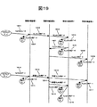
図20の情報ネットワークにおけるIPマルチキャスト通信の一例を、図21に示すパケットフローによって説明する。
【0149】
まず、マルチキャストサーバ2003が、マルチキャストデータ2101を送信する。情報中継装置1は、学習処理と中継処理を行う。VLAN−A(2010)に宛てて、ポート2へデータ2102を送信し、VLAN−B(2011)に宛てて、ポート3へデータ2104を送信する。ポート4への送信については、学習VLAN宛として学習処理(ステップ1006、1007、1008、1009)を行った後に、VLAN−A(2010)宛にデータ2103を送信し、VLAN−B(2010)宛にデータ2105を送信する(ステップ1010)。
【0150】
情報中継装置2では、情報中継装置1の送信したVLAN−A(2010)宛のデータ2103を受信して、学習処理(ステップ1006、1007、1008、1009)を行う。学習処理の後、中継処理(ステップ1010)を行い、ポート6へVLAN−A(2010)宛データ2106を送信する。この学習処理(ステップ1006、1007、1008、1009)において、受信ポートであるポート5は学習が有効なポートであるため、IPマルチキャスト学習テーブル70に登録する代表受信VLAN−ID703は、学習VLANのVLAN−ID21となる(ステップ1006)。また、送信ポートであるポート6は学習が有効なポートではないため(ステップ1302)、IPマルチキャスト学習テーブル70に登録する送信VLAN−ID708は、VLAN−AのVLAN−ID21(2010)となる(ステップ1303)。
【0151】
その後、情報中継装置2は、VLAN−B(2011)宛データ2105を受信する。IPマルチキャスト学習テーブル70の更新処理によって送信VLAN−ID708をVLAN−BのVLAN−ID21(2011)とする送信情報を追加登録し(ステップ1303)、中継処理によってVLAN−B(2011)宛にデータ2107を送信する(ステップ1010)。
【0152】
情報中継装置5は、本発明で示す学習機能等を備えない中継装置であるため、TCP/IP等のプロトコルで規定されている所定の中継処理が行われる。VLAN−A(2010)宛データ2106を受信すると、VLAN−A(2010)宛のデータ2108をポート8へ中継する。同様に、VLAN−B(2011)宛データ2107を受信すると、VLAN−B(2011)宛のデータ2109をポート8へ中継する。
【0153】
情報中継装置3では、情報中継装置5の送信したVLAN−A(2010)宛のデータ2108を受信すると、学習処理(ステップ1006、1007、1008、1009)を行う。学習処理(ステップ1006、1007、1008、1009)の後、中継処理(ステップ1010)を行い、ポート10へVLAN−A(2010)宛データ2110を送信する。この学習処理(ステップ1006、1007、1008、1009)においては、代表受信VLAN−ID703は、VLAN−A(2010)のVLAN−ID21である。また、ポート10は学習の有効なポートであるため、IPマルチキャスト学習テーブル70の送信VLAN−ID708に学習VLANのVLAN−ID21を登録する(ステップ1306)。
【0154】
その後、情報中継装置3は、VLAN−B(2011)宛のデータ2109を受信し、学習処理(ステップ1014、1015、1008、1009)を行う。学習処理(ステップ1014、1015、1008、1009)の後、中継処理(ステップ1010)を行い、ポート10へVLAN−B(2011)宛のデータ2111を送信する。ここで、VLAN−A(2010)宛データ2108受信時の学習処理(ステップ1006、1007、1008、1009)において、既にポート10に対する送信VLAN−ID708を学習VLANのVLAN−ID21とした登録がある(ステップ1305)。従って、学習処理(ステップ1014、1015、1008、1009)においては、IPマルチキャスト学習テーブル70の送信情報は更新されない。ポート10に対しての送信情報では、送信VLAN−ID708の登録は、学習VLANのVLAN−ID21のみである。なお、代表受信VLAN−ID703は、マルチキャストパケットのTTL値の比較(ステップ1101)の結果により、VLAN−A(2010)のVLAN−ID21のままで更新されない。
【0155】
情報中継装置4では、VLAN−A(2010)宛データ2110を受信すると、学習処理(ステップ1006、1007、1008、1009)と中継処理(ステップ1010)が行われる。この中継処理(ステップ1010)により、ポート12にはVLAN−A(2010)宛のデータ2112が送信される。また、VLAN−B(2011)宛データ2111を受信すると、学習処理(ステップ1014、1015、1008、1009)と中継処理(ステップ1010)が行なわれる。この中継処理(ステップ1010)により、VLAN−B(2011)宛のデータ2113が送信される。この学習処理(ステップ1014、1015、1008、1009)において、代表受信VLAN−ID703は学習VLANのVLAN−ID21となる(ステップ1306)。
【0156】
本発明に示す学習機能を備える各情報中継装置2001において、IPマルチキャスト学習テーブル70の有効/無効フラグ706が有効になった後に、マルチキャストサーバ2003が、同じ宛先のマルチキャストデータ2114を送信する。情報中継装置1は、IPマルチキャスト学習テーブル70の検索(ステップ1004)の結果に従い、送信情報に登録されているポート2、ポート3、ポート4に対し、学習済みマルチキャストの中継処理(ステップ1016)を行う。この際、ポート2には、VLAN−A(2010)宛データ2115を送信する。ポート3には、VLAN−B(2011)宛データ2116を送信する。ポート4には、学習VLAN宛データ2117を送信する。
【0157】
情報中継装置2では、情報中継装置1が送信した学習VLAN宛のデータ2117を受信する。IPマルチキャスト学習テーブル70の検索(ステップ1004)において、学習VLAN宛データ2117に対応する代表受信VLAN−ID703が、学習VLANのVLAN−ID21であるテーブルエントリがヒットする。ヒットしたIPマルチキャスト学習テーブル70には、送信ポート707に登録されているポート6に対応して、VLAN−AのVLAN−ID21(2010)およびVLAN−BのVLAN−ID21(2011)の2つの送信VLAN−ID708が登録されている。学習済みマルチキャストの中継処理(ステップ1016)により、学習が有効でないポート6に対し、VLAN−A(2010)宛のデータ2118とVLAN−B(2011)宛のデータ2119をそれぞれ送信する。
【0158】
情報中継装置5では、VLAN−A(2010)宛データ2106およびVLAN−B(2011)宛データ2107を受信した際の処理と同様な処理を行う。ポート8に対し、VLAN−A(2010)宛のデータ2120、およびVLAN−B(2011)宛のデータ2121をそれぞれ送信する。
【0159】
情報中継装置3では、情報中継装置5の送信したVLAN−A(2010)宛のデータ2120を受信する。IPマルチキャスト学習テーブル70の検索(ステップ1004)において、VLAN−A(2010)宛データ2120に対応する代表受信VLAN(703)が、VLAN−A(2010)であるテーブルエントリがヒットする(ステップ1005)。ヒットしたIPマルチキャスト学習テーブル70には、送信ポート707に登録されているポート11に対応して、学習VLANのVLAN−ID21が送信VLAN−ID708として登録されている。この登録に従い、ポート11に対し学習VLAN宛のデータ2122を送信する。
【0160】
情報中継装置3は、情報中継装置5の送信したVLAN−B(2011)宛データ2121を受信する。IPマルチキャスト学習テーブル70の検索(ステップ1004)の結果、VLAN−B(2011)宛データ2121に対応する代表受信VLAN−ID703は、VLAN−A(2010)のVLAN−ID21であり、VLAN−B(2011)のVLAN−ID21についての登録はない。従って、中継処理は行わずパケットを廃棄する。
【0161】
情報中継装置4では、情報中継装置4が送信した学習VLAN宛のデータ2122を受信する。学習済みマルチキャストの中継処理(ステップ1016)に従い、ポート12に対して、VLAN−A(2010)宛のデータ2123を送信する。ポート13に対しては、VLAN−B(2011)宛のデータ2124を送信する。
【0162】
以上が、図20の情報ネットワークにおけるIPマルチキャスト通信の一例である。
【0163】
このように、本発明で示す学習機能を有する情報中継装置を用いることにより、物理的な構成とは無関係に論理的に構成されるネットワーク間、例えばLANスイッチ等の装置において広く普及したVLAN等でのマルチキャスト通信において、物理的には同じ中継装置であるが論理的に異なるネットワーク等への送信を1回のみに抑制することが可能である。
【0164】
また、同一内容のデータを有するマルチキャストパケットを1回受信するのみで、所定の中継先の全てへ中継することにより、物理的に複雑に構成されたネットワーク上ほど、より少ないトラフィックでのマルチキャストパケットの配信が可能である。なお、同一内容とは、マルチキャストパケットの送信データの中身を意味する。
【0165】
従って、ネットワーク上のトラフィックを必要以上に増加させることなく、物理的なネットワーク構成に適応させたマルチキャストサービスを実現することが可能となる。
【0166】
また、情報中継装置におけるマルチキャスト中継処理の処理量を減らすことにより、情報中継装置にかかる負荷の軽減が実現できるため、より高速なマルチキャストの中継処理が可能となる。
【0167】
従って、高品質なマルチキャストサービスの実現および利用を図ることができる。
【0168】
なお、本発明は、上述の実施の形態に限定されるものではない。たとえば、本発明の学習処理の対象となるマルチキャストサービスを行うプロトコルとしては、上述の実施の形態において例示したIPv4マルチキャスト、IPv6マルチキャストに限らない。本発明と同様のマルチキャスト学習テーブルを用いることにより、他のプロトコルにおいても適用することが可能である。
【0169】
【発明の効果】
以下、本発明により達成される効果を簡単に説明する。
【0170】
本発明の情報中継装置によれば、ネットワークのトラフィックを必要以上に増加させることなく、マルチキャストサービスを実現することが可能である。
【0171】
マルチキャストサービスを提供する情報中継装置におけるマルチキャスト中継処理の高速化を実現することが可能である。
【0172】
マルチキャストサービスに起因するネットワークのトラフィックの増加の抑制と、情報中継装置におけるマルチキャスト中継処理の高速化による高品質なマルチキャストサービスの実現および利用を図ることが可能である。
【図面の簡単な説明】
【図1】本発明による情報中継装置の一例を有する情報ネットワークの構成概念図である。
【図2】VLANテーブルの一例を示す概念図である。
【図3】マルチキャストテーブルの一例を示す概念図である。
【図4】マルチキャスト学習テーブルの一例を示す概念図である。
【図5】学習済みマルチキャスト情報テーブルの一例を示す概念図である。
【図6】IPマルチキャストテーブルの一例を示す概念図である。
【図7】IPマルチキャスト学習テーブルの一例を示す概念図である。
【図8】学習済みIPマルチキャスト情報テーブルの一例を示す概念図である。
【図9】マルチキャスト受信処理の一例を示すフローチャートである。
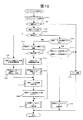
【図10】マルチキャスト中継処理の一例を示すフローチャートである。
【図11】マルチキャスト学習テーブルの受信情報更新処理の一例を示すフローチャートである。
【図12】未学習IPマルチキャストの中継処理の一例を示すフローチャートである。
【図13】マルチキャスト学習テーブルの送信情報更新処理の一例を示すフローチャートである。
【図14】学習済みマルチキャストの中継処理の一例を示すフローチャートである。
【図15】本発明による情報中継装置を有する情報ネットワークにおけるIPマルチキャスト通信のパケットフローの一例を示す概念図である。
【図16】IPv4マルチキャストにおいてのマルチキャストパケットのヘッダフォーマットの一例を示す概念図である。
【図17】学習済みIPv4マルチキャスト情報テーブルの一例を示す概念図である。
【図18】本発明による情報中継装置の一例を有する情報ネットワークの構成概念図である。
【図19】本発明による情報中継装置を有する情報ネットワークにおけるIPマルチキャスト通信のパケットフローの一例を示す概念図である。
【図20】本発明による情報中継装置の一例を有する情報ネットワークの構成概念図である。
【図21】本発明による情報中継装置を有する情報ネットワークにおけるIPマルチキャスト通信のパケットフローの一例を示す概念図である。
【符号の説明】
20・・・VLANテーブル
30・・・マルチキャストテーブル
40・・・マルチキャスト学習テーブル
50・・・学習済みマルチキャスト情報テーブル
60・・・IPマルチキャストテーブル
70・・・IPマルチキャスト学習テーブル
80・・・学習済みIPマルチキャスト情報テーブル
101・・・情報中継装置
102・・・VLAN
103・・・マルチキャストサーバ
104・・・端末
105・・・ネットワーク
110・・・通信処理部
111・・・マルチキャスト受信処理部
112・・・マルチキャスト中継処理部
113・・・マルチキャストアドレス学習処理部
114・・・マルチキャストプロトコル処理部
115・・・ポート
1600・・・ヘッダフォーマット
1700・・・学習済みIPv4マルチキャスト情報テーブル[0001]
BACKGROUND OF THE INVENTION
The present invention relates to an information relay technique, and more particularly to a technique effective when applied to information network connection equipment such as a LAN switch.
[0002]
[Prior art]
In the field of information communication, there is generally a method called multicast distribution as a method for simultaneously distributing the same data from a single host to a plurality of hosts. In multicast distribution, a specific group is formed by a plurality of hosts, and the same data is distributed to all the hosts in the specific group using one multicast packet. TCP / IP (Transmission Control Protocol / Internet Protocol), which is a standard protocol on the Internet, also has a technique called IP multicast using this multicast distribution.
[0003]
IP multicast is a method of performing multicast by IP address. In IP multicast, a specific IP address called an IP multicast address is defined for each specific group, and by using an IP multicast packet with the IP multicast address as a destination IP address, the same data is sent to all hosts in the specific group. To deliver. IP multicast refers to relaying multicast packets sent by a multicast server to a receiving terminal such as a host that has declared to join the multicast by relay processing between specific groups without being aware of the configuration within the specific group. Say. According to this IP multicast technology, when distributing the same data to receiving terminals such as a plurality of hosts, it is not necessary to transmit data for each receiving terminal, but to transmit only one packet. There is an advantage that distribution to all receiving terminals in the group becomes possible.
[0004]
The IP multicast is a protocol in the third layer (network layer) of the OSI (Open Systems Interconnection) reference model, and is a protocol for realizing multicast communication between the second layer (data link layer) networks.
[0005]
On the other hand, VLAN (Virtual) is a technology for virtually constructing a second layer (data link layer) network that is a standard for IP multicast data distribution.
LAN (Local Area Network).
[0006]
In the VLAN, when addition, deletion, change, or the like of a network configuration occurs, a second layer (data link layer) network is logically constructed without being limited to a physical network configuration. A second layer (data link layer) network is logically constructed by communication devices such as hosts connected to different information relay devices in a physical configuration, and communication by the second layer (data link layer) is performed. Is possible. This VLAN has an advantage that it is not necessary to change the physical network configuration when changing the configuration of the second layer (data link layer) network.
[0007]
VLAN is a technique for constructing a second layer (data link layer) network and does not depend on a third layer (network layer) protocol such as IP. On the other hand, the third layer protocol such as IP does not depend on the construction method of the second layer (data link layer) network.
[0008]
There are several methods for implementing VLANs. For example, in the
[0009]
[Problems to be solved by the invention]
There is a case where a specific group in IP multicast is configured by an IP subnet. In this case, when an IP subnet is assigned to the VLAN, a specific group in the IP multicast can be configured by the VLAN. The multicast packet transmitted from the multicast server is subjected to multicast relay processing between the VLANs from the VLAN that is the IP subnet to which the multicast server belongs to a plurality of VLANs that are the IP subnet to which the receiving terminal belongs.
[0010]
However, IP multicast applied to relay processing between VLANs is a third layer (network layer) protocol, and is not linked to a VLAN for constructing a second layer (data link layer) network. Therefore, when relaying between different VLANs and relaying within the VLAN, the same multicast packet makes a round trip to the same relay device multiple times, or the duplicated multicast packet with the same content is physically the same In some cases, the relay device passes through a plurality of times, and more traffic than necessary is generated. This problem is caused by allocating an IP subnet to the VLAN to realize IP multicast.
[0011]
Further, when the number of logically set VLANs increases, the number of IP multicast logical relay destinations that perform relay processing between VLANs increases. Therefore, when a large number of multicast packets are relayed to the physically same relay device, the amount of multicast packets relayed increases, and the load in the IP multicast relay processing increases.
[0012]
Therefore, in the multicast service, controlling or reducing network traffic is, for example, the spread of multicast services such as information distribution and video conferencing in a LAN environment in which communication devices having a VLAN function such as a LAN switch are widespread. Is an important technical issue.
[0013]
An object of the present invention is to solve such a problem and provide an information relay technique capable of providing a multicast service without increasing network traffic more than necessary.
[0014]
Another object of the present invention is to provide an information relay technique capable of reducing the load in the multicast relay processing of the information relay device and realizing higher-speed and high-quality multicast relay processing.
[0015]
Furthermore, another object of the present invention is to provide an information relay capable of suppressing and increasing the network traffic in the multicast service and realizing and using a high-quality multicast service by speeding up the multicast relay processing in the information relay device. To provide technology.
[0016]
[Means for Solving the Problems]
According to the present invention, a multicast relay destination registration table, for example, a multicast learning table is provided in an information relay apparatus that relays information in a plurality of logical information networks. As a learning process, the information relay apparatus receives multicast packets for the first time after constructing a VLAN, and thereafter registers predetermined information related to relay of the multicast packets in the multicast relay destination registration table. As a result, the information relay apparatus obtains a multicast relay destination registration table when relaying one multicast packet to one destination as a learning result.
[0017]
That is, the information relay apparatus registers predetermined information related to relay of one multicast packet for one destination after receiving the multicast packet for the first time after VLAN construction until the learning process is completed. To register in the table. Further, when the multicast packet is relayed from the relay device that is physically the same relay device but included in a logically different network to the same destination together with the registration processing in the multicast relay destination registration table, the multicast With reference to the relay destination registration table, if these multicast packets are the same multicast packet, the same multicast packet as these multicast packets is transmitted only once. As a result, the information relay apparatus can suppress the same multicast packet that has been relayed a plurality of times conventionally to only one relay. When the information relay apparatus relays the multicast packet after the learning process is completed, the information relay apparatus transmits the received multicast packet to all the transmission destinations registered in the multicast relay destination registration table. As a result, the multicast packet is included in a logically different network and is relayed only once through the physically same relay apparatus.
[0018]
For example, in IPv4 multicast, a predetermined relay destination of a multicast packet for a destination is registered in a multicast relay destination registration table together with information for rewriting the multicast packet such as TTL (Time to Live). As a result, within the time from when the multicast packet is first received until the learning process is completed, the information relay device is physically the same relay device but the same destination from the logically different network. When the multicast packet is relayed toward the destination, if these data are the same data, only the packet with the maximum TTL value in the IP header is relayed. Further, after the learning process is completed, the information relay apparatus, when relaying a multicast packet having the maximum TTL value toward one destination, uses the TTL based on the rewrite information registered in the multicast relay destination registration table. After rewriting the packet, etc., it is relayed to all predetermined relay destinations.
[0019]
DETAILED DESCRIPTION OF THE INVENTION
Embodiments of the present invention will be described below.
[0020]
FIG. 1 is a conceptual diagram of an information network configuration having an embodiment of an information relay device according to the present invention. The information relay device is an inter-network connection device that connects logically configured networks such as a LAN switch.
[0021]
The information network shown in FIG. 1 performs an information relay operation between a plurality of VLANs 102 (VLAN-A (102-1), VLAN-B (102-2), learning VLAN (102-3)) and a plurality of
[0022]
In the case of the present embodiment, each
[0023]
The
[0024]
As shown in the flowchart of FIG. 9 to be described later, the multicast reception processing unit 111 performs an operation of distributing multicast packet processing to either multicast relay processing or multicast protocol processing according to the type of multicast packet. The multicast reception processing unit 111 is configured by software or the like.
[0025]
As shown in the flowchart of FIG. 10 to be described later, the multicast
[0026]
The multicast address
[0027]
The multicast
[0028]
Details of the VLAN table 20 of FIG. 1 are shown in the VLAN table 20 of FIG. In the VLAN table 20, the VLAN-
[0029]
The learning in the present invention is to record in the multicast learning table 40 all the relay destinations to be transmitted by the own device when each
[0030]
Further, learning is effective if both the own
[0031]
The learning VLAN 102-3 is set when the own
[0032]
The VLAN-
[0033]
Details of the multicast table 30 of FIG. 1 are shown in the multicast table 30 of FIG. The multicast table 30 is composed of entries associated with information classified as reception information and transmission information as one element.
[0034]
As reception information, a
[0035]
As transmission information corresponding to reception information, a transmission VLAN-
[0036]
The
[0037]
Details of the multicast learning table 40 of FIG. 1 are shown in the multicast learning table 40 of FIG. The multicast learning table 40 is a table that records the learning result of the multicast packet relayed from the time when the multicast packet is first received until the learning process is completed. The multicast learning table 40 includes entries associated with information classified as reception information and transmission information as one element.
[0038]
As reception information, a
[0039]
The transmission information is provided corresponding to the reception information and is used when transmitting a multicast packet. In the transmission information, the
[0040]
Similar to the multicast table 30, the
[0041]
When the learning process is completed, it is possible to achieve the effect of the present invention by relaying the multicast packet using the multicast learning table 40. That is, when relaying a multicast packet, the
[0042]
The
[0043]
In the learned multicast information table 50, as shown in FIG. 5, a destination multicast address 51, a
[0044]
Similar to the multicast table 30, the
[0045]
The multicast packet relay process will be described below.
[0046]
In the following description, an IP multicast learning process that is a multicast protocol in TCP / IP will be described as an example of the multicast learning process of the
[0047]
Regarding IP multicast, those corresponding to the multicast table 30, the multicast learning table 40, and the learned multicast information table 50 are the IP multicast table 60 (FIG. 6), the IP multicast learning table 70 (FIG. 7), and the learned IP. It is a multicast information table 80 (FIG. 8).
[0048]
In the IP multicast table 60, as shown in FIG. 6, the destination IP multicast address 61 and the
[0049]
In the IP multicast learning table 70, as shown in FIG. 7, the destination
[0050]
Also, the TTL subtraction number 709 and the transmission source second layer address 710 correspond to the
[0051]
In the learned IP multicast information table 80, as shown in FIG. 8, the destination multicast address 51 in the learned multicast information table 50 is the destination
[0052]
Hereinafter, an example of the operation of the
[0053]
First, the operation of the multicast reception processing unit 111 will be described using the flowchart of FIG.
[0054]
It is determined whether the received packet is a multicast packet (step 91), and if it is a multicast packet, it is determined whether it is a multicast protocol packet (step 92). If the packet is not a multicast packet, normal packet relay processing is performed. A multicast protocol packet is a control protocol packet for a multicast packet. This control protocol includes, for example, a protocol for determining which
[0055]
If the multicast packet is a multicast protocol packet, predetermined multicast protocol processing is performed (step 94). If the packet is not a multicast protocol packet, the multicast
[0056]
Next, the multicast relay process performed in (step 93) will be described.
[0057]
An example of the multicast relay process is shown in the flowchart of FIG. The multicast
[0058]
The IP multicast table 60 is searched based on the destination IP multicast address 61, the
[0059]
If the search of the IP multicast table 60 is not hit (step 1002), the multicast packet is discarded because the
[0060]
If the search is hit (step 1002), the IP multicast learning table 70 is searched (step 1004). In this search, the destination
[0061]
If there is no hit in the search of the IP multicast learning table 70 (step 1005), a new entry is created in the IP multicast learning table 70 and reception information is registered (step 1006). The reason for performing this processing is that the received multicast packet and the multicast packet having the same destination
[0062]
Next, a new entry is created in the learned IP multicast information table 80 (step 1007). A new entry is created in the learned IP multicast information table 80. The destination
[0063]
Next, transmission information update processing (step 1008) of the IP multicast learning table 70 shown in the flowchart of FIG. Thereafter, the valid /
[0064]
Finally, the multicast packet relay process is performed by the unlearned multicast relay process shown in the flowchart of FIG. 12 (step 1010).
[0065]
The process of creating a new entry and registering received information in the IP multicast learning table 70 (step 1006) and creating a new entry in the learned IP multicast information table 80 (step 1007) are in the order of each other's process. It is also preferable to replace.
[0066]
On the other hand, if the IP multicast learning table 70 is hit (step 1005) and the valid /
[0067]
As a result of the search of the learned IP multicast information table 80 (step 1012), the VLAN-
[0068]
Furthermore, the received VLAN and the reception port of the received multicast packet are additionally registered in the entry of the learned IP multicast information table 80 corresponding to the destination multicast address and the source address of the received multicast packet (step 1015).
[0069]
Thereafter, the processing of (Step 1008), (Step 1009), and (Step 1010) described above is performed. Note that it is also preferable that the processing order of the received information update process (step 1014) of the multicast learning table and the additional registration (step 1015) to the entry of the learned IP multicast information table 80 is interchanged.
[0070]
Further, as a result of the search of the learned IP multicast information table 80 (step 1012), the VLAN-
[0071]
On the other hand, a case where the valid /
[0072]
If the VLAN-
[0073]
The above is an example of the multicast relay process in (step 93) of FIG.
[0074]
Next, the reception information update process of the multicast learning table in (Step 1014) of FIG. 10 will be described using the flowchart of FIG.
[0075]
First, the TTL value of the IP header of the received multicast packet is compared with the learning
[0076]
When the TTL value of the received multicast packet is less than or equal to the value of the learning
[0077]
When the TTL value of the received multicast packet is larger than the value of the learning
[0078]
Next, the VLAN table 20 is searched (step 1103). If the reception port corresponding to the reception VLAN of the received multicast packet is an invalid learning port as a result of this search (step 1104), the received multicast packet is stored in the representative reception VLAN-
[0079]
Finally, the TTL subtraction number 709 registered as transmission information in the IP multicast learning table 70 is added to the difference between the TTL value of the received multicast packet and the value of the previous
[0080]
The above is an example of the received information update process of the IP multicast learning table 70 in (Step 1014) of FIG.
[0081]
Next, unlearned multicast relay processing in
[0082]
First, according to the search result of the IP multicast table 60 in FIG. 10 (step 1001), the following processing is performed for all the transmission VLANs and transmission ports registered in the transmission information of the IP multicast table 60 (step 1201). .
[0083]
If the received VLAN of the received multicast packet is different from the VLAN to be transmitted (step 1202), the TTL value in the IP header of the multicast packet is subtracted by 1 ((TTL value) -1) (step 1203). If the value of TTL after subtraction is greater than 0 (TTL> 0) (step 1204), the IP header checksum calculation associated with TTL subtraction is performed. Also, the transmission source second layer (data link layer) address of the multicast packet is changed to an address corresponding to the VLAN to be transmitted (step 1205). The checksum calculation is, for example, error check. Note that the checksum calculation is performed in the case of IPv4 multicast, and there is no need for checksum calculation processing in IPv6 multicast (hereinafter, checksum calculation is performed only in IPv4 multicast).
[0084]
After (Step 1205), packet transmission processing (Step 1206) is performed. The packet transmission process is a process in which the
[0085]
On the other hand, if the received VLAN of the received multicast packet is the same as the transmitted VLAN (step 1202), the TTL value is not subtracted because the multicast packet is relayed within the same VLAN. This is because the router that connects different segments conventionally has the purpose of unifying TTL not to be subtracted in transmission / reception of packets between hosts belonging to the same segment. Therefore, in this case, the packet transmission process (step 1206) is performed without performing the processes of (step 1203), (step 1204), and (step 1205).
[0086]
On the other hand, if {TTL> 0} is not satisfied in (Step 1204), the processing of (Step 1205) and (Step 1206) described above is not performed, and the relay processing is terminated.
[0087]
The above is an example of the unlearned multicast relay process in (step 1010) of FIG.
[0088]
Next, the transmission information update process of the IP multicast learning table 70 in (step 1008) of FIG. 10 will be described using the flowchart of FIG.
[0089]
First, according to the search result of the IP multicast table 60 in (Step 1001) of FIG. 10, the following processing is performed for all the transmission ports and transmission VLANs registered in the IP multicast table 60 (Step 1301).
[0090]
First, the case where the VLAN table 20 is searched and the transmission port corresponding to the transmission VLAN is an invalid learning port (step 1302) will be described. The transmission information of the IP multicast learning table 70 that has been subjected to reception information registration processing in (Step 1006) or reception information update processing in (Step 1014) is newly added to the transmission port 707, transmission VLAN-
[0091]
Next, a case where the VLAN table 20 is searched and the transmission port corresponding to the transmission VLAN is an effective learning port (step 1302) will be described. When the transmission port of the search result matches the
[0092]
On the other hand, if the transmission port does not match the
[0093]
On the other hand, when the transmission VLAN-
[0094]
If the registered TTL subtraction number 709 is equal to or smaller than the TTL subtraction number of the received packet (step 1307), the process of (step 1308) is not performed and the transmission information update process of the IP multicast learning table 70 is terminated. To do.
[0095]
The above is the outline of the transmission information update process of the IP multicast learning table 70 in (Step 1008) of FIG.
[0096]
Next, the learning multicast relay operation in (step 1016) of FIG. 10 will be described using the flowchart of FIG.
[0097]
The IP multicast learning table 70 is searched, and the following processing is performed for all the transmission ports 707 registered as transmission information (step 1401).
[0098]
First, according to the TTL subtraction number 709 registered corresponding to the transmission port, the registered TTL subtraction number is subtracted from the TTL value of the IP header of the multicast packet (step 1402).
[0099]
If TTL> 0 as a result of the subtraction (step 1403), the source second layer address in the IP header of the multicast packet is replaced with the registered source second layer address 710 corresponding to the transmission port. In addition, recalculation of the checksum accompanying the TTL subtraction is performed (step 1404). After that, the
[0100]
If TTL> 0 is not satisfied in
[0101]
The above is an example of the relay processing of the learned multicast in (Step 1016) of FIG.
[0102]
Next, an information network is configured using the information relay device described above. An example of IP multicast communication is shown using this information network.
[0103]
FIG. 15 is an example of a packet flow of IP multicast communication in the information network of FIG. In the information network of FIG. 1, the
[0104]
First, the
[0105]
Next, based on the result of the search of the IP multicast table 60 (step 1001), first, relay processing in the VLAN-A (102-1) is performed. From the
[0106]
Subsequently, the relay process from the VLAN-A (102-1) to the VLAN-B (102-2) is performed according to the search result of the IP multicast table 60 (step 1001). Transmission information registration processing of the IP multicast learning table 1230 is performed for the
[0107]
The
[0108]
Finally, a timer is set (step 1009). By this timer, the valid /
[0109]
The
[0110]
Next, the relay processing in VLAN-A (102-1) is performed based on the result of the search of the IP multicast table 60 (step 1001). Transmission information is registered to the port 5 where the terminal A2 exists (step 1008), and the data 1504 addressed to the VLAN-A (102-1) is transmitted. Since learning is not effective for port 5 (1302), VLAN-
[0111]
Thereafter, the
[0112]
The operation in the
[0113]
Thereafter, after the validity /
[0114]
The
[0115]
The operation in the
[0116]
The above is an example of IP multicast communication by the
[0117]
FIG. 16 shows an example of a
[0118]
In the case of IPv4 multicast, it is also preferable to use the
[0119]
Hereinafter, an example of the operation when the learned IPv4 multicast information table 1700 is used will be described.
[0120]
When the learned IPv4 multicast information table 1700 is used, in the multicast relay process (step 1007) shown in FIG. 10, the ID value of the IP header of the received multicast packet is added to the newly created learned IPv4 multicast information table 1700 entry. Register.
[0121]
In the search of the learned IPv4 multicast information table 1700 in (Step 1012), the value of the ID in the IP header of the received multicast packet is compared with the learned
[0122]
In (Step 1013), if the ID comparison in (Step 1012) matches, it is determined that learning is necessary, and the process proceeds to (Step 1014). If the IDs do not match in (Step 1012), it is determined that learning is not necessary. In (Step 1015), since the values of the received multicast packet and the learning
[0123]
The above is an example of the operation when the learned IPv4 multicast information table 1700 shown in FIG. 17 is used.
[0124]
FIG. 18 shows an example in which another information network is constructed using the
[0125]
In the information network of FIG. 18, a plurality of information relay apparatuses 1801 (
[0126]
A
[0127]
It is assumed that terminal A1, terminal A2, terminal B1, and terminal B2 have joined multicast group members transmitted by
[0128]
Further, the ports (
[0129]
Of the multicast table 30 possessed by each
[0130]
An example of IP multicast communication in the information network of FIG. 18 will be described using the packet flow shown in FIG.
[0131]
First, the
[0132]
Next, based on the search result of the IP multicast table 60 (step 1001), a relay process in the VLAN-A (1810) is performed. The transmission information of the IP multicast learning table 70 is registered from the
[0133]
In the
[0134]
Next, a relay process in the VLAN-A (1810) is performed based on the result of the search of the IP multicast table 60 (step 1001). Transmission information is registered in the
[0135]
The
[0136]
Next, relay processing in VLAN-A (1810) is performed according to the result of the search of IP multicast table 60 (step 1001). The transmission information of the IP multicast learning table 70 is registered from the
[0137]
Further, according to the result of the search of the IP multicast table 60 (step 1001), the relay processing from VLAN-A (1810) to VLAN-B (1811) is performed. Transmission information registration processing is performed for ports 5 and 6 in which the
[0138]
The
[0139]
Thereafter, the
[0140]
Thereafter, after the validity /
[0141]
The
[0142]
The
[0143]
The operation in the
[0144]
The above is an example of IP multicast communication in the information network of FIG.
[0145]
FIG. 20 is an example of another information network of the present invention.
[0146]
In the information network shown in FIG. 20, a plurality of information relay apparatuses 2001 (
[0147]
It is assumed that the terminal A1, the terminal A2, the terminal B1, and the terminal B2 are subscribed to a multicast group member transmitted by the
[0148]
An example of IP multicast communication in the information network of FIG. 20 will be described with reference to the packet flow shown in FIG.
[0149]
First, the
[0150]
The
[0151]
Thereafter, the
[0152]
Since the information relay device 5 is a relay device that does not have the learning function and the like shown in the present invention, a predetermined relay process defined by a protocol such as TCP / IP is performed. When the
[0153]
When the
[0154]
Thereafter, the
[0155]
When the
[0156]
In each
[0157]
The
[0158]
The information relay device 5 performs the same processing as when the VLAN-A (2010) -addressed
[0159]
The
[0160]
The
[0161]
The
[0162]
The above is an example of IP multicast communication in the information network of FIG.
[0163]
In this way, by using the information relay apparatus having the learning function shown in the present invention, it is possible to use the VLAN widely used in apparatuses such as LAN switches, for example, between logically configured networks regardless of the physical configuration. In the multicast communication, it is possible to suppress transmission to a network or the like that is physically the same relay apparatus but logically only once.
[0164]
In addition, by receiving a multicast packet having the same content data only once and relaying it to all of the predetermined relay destinations, it is possible to reduce the number of multicast packets with less traffic on a physically complex network. Distribution is possible. The same content means the contents of the transmission data of the multicast packet.
[0165]
Therefore, it is possible to realize a multicast service adapted to the physical network configuration without increasing traffic on the network more than necessary.
[0166]
Further, since the load on the information relay apparatus can be reduced by reducing the processing amount of the multicast relay process in the information relay apparatus, a higher-speed multicast relay process can be performed.
[0167]
Accordingly, it is possible to realize and use a high-quality multicast service.
[0168]
The present invention is not limited to the embodiment described above. For example, the protocol for performing the multicast service that is the object of the learning process of the present invention is not limited to the IPv4 multicast and the IPv6 multicast exemplified in the above embodiment. By using a multicast learning table similar to the present invention, it can be applied to other protocols.
[0169]
【The invention's effect】
Hereinafter, effects achieved by the present invention will be briefly described.
[0170]
According to the information relay apparatus of the present invention, it is possible to realize a multicast service without increasing network traffic more than necessary.
[0171]
It is possible to increase the speed of multicast relay processing in an information relay device that provides a multicast service.
[0172]
It is possible to realize and use a high-quality multicast service by suppressing an increase in network traffic caused by the multicast service and by speeding up the multicast relay processing in the information relay apparatus.
[Brief description of the drawings]
FIG. 1 is a conceptual diagram of a configuration of an information network having an example of an information relay device according to the present invention.
FIG. 2 is a conceptual diagram illustrating an example of a VLAN table.
FIG. 3 is a conceptual diagram illustrating an example of a multicast table.
FIG. 4 is a conceptual diagram illustrating an example of a multicast learning table.
FIG. 5 is a conceptual diagram illustrating an example of a learned multicast information table.
FIG. 6 is a conceptual diagram illustrating an example of an IP multicast table.
FIG. 7 is a conceptual diagram illustrating an example of an IP multicast learning table.
FIG. 8 is a conceptual diagram showing an example of a learned IP multicast information table.
FIG. 9 is a flowchart illustrating an example of multicast reception processing.
FIG. 10 is a flowchart illustrating an example of multicast relay processing.
FIG. 11 is a flowchart illustrating an example of reception information update processing of a multicast learning table.
FIG. 12 is a flowchart illustrating an example of an unlearned IP multicast relay process.
FIG. 13 is a flowchart illustrating an example of transmission information update processing of a multicast learning table.
FIG. 14 is a flowchart illustrating an example of relay processing of learned multicast.
FIG. 15 is a conceptual diagram showing an example of a packet flow of IP multicast communication in an information network having an information relay device according to the present invention.
FIG. 16 is a conceptual diagram illustrating an example of a header format of a multicast packet in IPv4 multicast.
FIG. 17 is a conceptual diagram illustrating an example of a learned IPv4 multicast information table.
FIG. 18 is a conceptual diagram of a configuration of an information network having an example of an information relay device according to the present invention.
FIG. 19 is a conceptual diagram showing an example of a packet flow of IP multicast communication in an information network having an information relay device according to the present invention.
FIG. 20 is a conceptual diagram of a configuration of an information network having an example of an information relay device according to the present invention.
FIG. 21 is a conceptual diagram showing an example of a packet flow of IP multicast communication in an information network having an information relay device according to the present invention.
[Explanation of symbols]
20 ... VLAN table
30 ... Multicast table
40 ... Multicast learning table
50: Learned multicast information table
60 ... IP multicast table
70 ... IP multicast learning table
80: Learned IP multicast information table
101: Information relay device
102 ... VLAN
103 ... Multicast server
104 ... Terminal
105 Network
110: Communication processing unit
111 ... Multicast reception processing unit
112 ... Multicast relay processing unit
113 ... Multicast address learning processing unit
114 ... Multicast protocol processor
115 ... Port
1600 ... Header format
1700... Learned IPv4 multicast information table
Claims (2)
複数のポートを有し、前記情報ネットワークからマルチキャストパケットを受信する受信部と、
前記受信部で第1のマルチキャストパケットを受信すると、当該第1のマルチキャストパケットの宛先マルチキャストアドレス、送信元アドレス、及び受信元ネットワーク及び受信ポート情報を記憶する記憶部と、
前記第1のマルチキャストパケットと同一送信元且つ同一宛先の前記第2のマルチキャストパケットを前記受信部で受信すると、当該第2のマルチキャストパケットを受信したネットワークと前記記憶部に記憶している前記第1のマルチキャストパケットを受信したネットワークとが一致するか及び前記第2のマルチキャストパケットを受信したポートと前記記憶部に記憶している前記第1のマルチキャストパケットを受信したポートとが一致するかを判断して、該判断の結果、いずれも一致する場合は、前記第2のマルチキャストパケットの中継処理を行い、前記判断の結果、いずれかが不一致と判断したとき当該第2のマルチキャストパケットの中継動作を抑止する制御部とを有することを特徴とするネットワーク中継装置。A network relay device that performs packet data relay operations in a plurality of logical information networks,
A receiver having a plurality of ports and receiving a multicast packet from the information network;
When the receiving unit receives the first multicast packet, the storage unit stores the destination multicast address, the transmission source address, and the reception source network and reception port information of the first multicast packet;
When the receiving unit receives the second multicast packet having the same source and the same destination as the first multicast packet, the first multicast packet stored in the storage unit and the network that has received the second multicast packet Whether the network that received the second multicast packet matches, and whether the port that received the second multicast packet matches the port that received the first multicast packet stored in the storage unit As a result of the determination, if both match, relay processing of the second multicast packet is performed, and if any of the determination results in mismatching, the relay operation of the second multicast packet is suppressed. And a network relay device .
前記制御部は、当該第2のマルチキャストパケットを受信したネットワークと前記記憶部に記憶している前記第1のマルチキャストパケットを受信したネットワークとが一致し且つ前記第2のマルチキャストパケットを受信したポートと前記記憶部に記憶している前記第1のマルチキャストパケットを受信したポートとが一致すると判断したとき、前記記憶部で前記第1のマルチキャストパケットの送信先として記憶されているポート毎に、当該ポート毎に記憶されている生存情報よりも、前記第2のマルチキャストパケットの生存情報が大きい場合は、前記記憶部に記憶されている生存情報を前記第2のマルチキャストパケットの生存情報に更新するとともに、前記記憶部に記憶されているポート毎の生存情報減算数を更新し、前記更新された生存情報減算数を用いて前記第2のマルチキャストパケットの生存情報を更新して当該ポート毎に送信させることを特徴とするネットワーク中継装置。The network relay device according to claim 1,
The control unit includes a port where the network that has received the second multicast packet matches the network that has received the first multicast packet stored in the storage unit, and the port that has received the second multicast packet. When it is determined that the port that received the first multicast packet stored in the storage unit matches, for each port stored as the transmission destination of the first multicast packet in the storage unit, the port When the survival information of the second multicast packet is larger than the survival information stored every time, the survival information stored in the storage unit is updated to the survival information of the second multicast packet, Update the survival information subtraction number for each port stored in the storage unit, and update the updated Network relay device according to claim existence information using the number of subtraction to update the existence information of the second multicast packet to be transmitted for each said port.
Priority Applications (2)
| Application Number | Priority Date | Filing Date | Title |
|---|---|---|---|
| JP28242699A JP3812239B2 (en) | 1999-10-04 | 1999-10-04 | Network relay device |
| US09/656,138 US6950431B1 (en) | 1999-10-04 | 2000-09-06 | Network relay apparatus |
Applications Claiming Priority (1)
| Application Number | Priority Date | Filing Date | Title |
|---|---|---|---|
| JP28242699A JP3812239B2 (en) | 1999-10-04 | 1999-10-04 | Network relay device |
Publications (3)
| Publication Number | Publication Date |
|---|---|
| JP2001111591A JP2001111591A (en) | 2001-04-20 |
| JP2001111591A5 JP2001111591A5 (en) | 2005-02-24 |
| JP3812239B2 true JP3812239B2 (en) | 2006-08-23 |
Family
ID=17652265
Family Applications (1)
| Application Number | Title | Priority Date | Filing Date |
|---|---|---|---|
| JP28242699A Expired - Fee Related JP3812239B2 (en) | 1999-10-04 | 1999-10-04 | Network relay device |
Country Status (2)
| Country | Link |
|---|---|
| US (1) | US6950431B1 (en) |
| JP (1) | JP3812239B2 (en) |
Families Citing this family (27)
| Publication number | Priority date | Publication date | Assignee | Title |
|---|---|---|---|---|
| US8495167B2 (en) * | 2001-08-02 | 2013-07-23 | Lauri Valjakka | Data communications networks, systems, methods and apparatus |
| US8199636B1 (en) * | 2002-10-18 | 2012-06-12 | Alcatel Lucent | Bridged network system with traffic resiliency upon link failure |
| US7590114B1 (en) * | 2003-03-24 | 2009-09-15 | Marvell International Ltd | Efficient IP multicast bridging in ethernet switches |
| US20050141502A1 (en) * | 2003-12-30 | 2005-06-30 | Alok Kumar | Method and apparatus to provide multicast support on a network device |
| JP4373271B2 (en) * | 2004-05-14 | 2009-11-25 | 富士通株式会社 | Method and program for grasping network configuration of virtual LAN in node network |
| KR100716163B1 (en) * | 2004-12-23 | 2007-05-10 | 삼성전자주식회사 | Tunneling Method and Apparatus for Multicasting Between IPv4 Network and IPv6 Network |
| CN100393069C (en) * | 2004-12-29 | 2008-06-04 | 中兴通讯股份有限公司 | Method of differentiating multiple services for anti IP data stream in multicast to impact communication system |
| CN100442706C (en) * | 2005-04-19 | 2008-12-10 | 华为技术有限公司 | Method for making maintaining node labels to match with media visiting controlled addresses |
| JP5107508B2 (en) * | 2005-04-26 | 2012-12-26 | 株式会社アイ・オー・データ機器 | Display management system |
| JP4231061B2 (en) | 2006-05-10 | 2009-02-25 | 株式会社日立コミュニケーションテクノロジー | Subscriber connection device and network system |
| US20080107109A1 (en) * | 2006-11-03 | 2008-05-08 | General Instrument Corporation | Method and Apparatus for Managing Multicast Traffic in a Network at the Data Link or Level 2 Layer |
| JP2009094832A (en) * | 2007-10-10 | 2009-04-30 | Nec Access Technica Ltd | Multicast data distribution apparatus, distribution method therefor, and distribution control program thereof |
| JP4866381B2 (en) * | 2008-03-12 | 2012-02-01 | 株式会社日立製作所 | Network system and subscriber connection device |
| US8208418B1 (en) * | 2009-01-16 | 2012-06-26 | Extreme Networks, Inc. | Methods, systems, and computer readable media for conserving multicast port list resources in an internet protocol (IP) packet forwarding device |
| KR101257724B1 (en) * | 2009-03-13 | 2013-04-23 | 무라다기카이가부시끼가이샤 | First relay server and second relay server |
| JP5210245B2 (en) | 2009-05-28 | 2013-06-12 | アラクサラネットワークス株式会社 | Network relay device and inter-network relay method |
| JP5233898B2 (en) * | 2009-07-31 | 2013-07-10 | 富士通株式会社 | Routing table rewriting method, data transfer device, and program |
| JP5387300B2 (en) * | 2009-09-30 | 2014-01-15 | 村田機械株式会社 | Relay server and relay communication system |
| JP5672779B2 (en) * | 2010-06-08 | 2015-02-18 | ソニー株式会社 | Transmission control apparatus and transmission control method |
| US8447909B2 (en) | 2010-07-19 | 2013-05-21 | International Business Machines Corporation | Register access in distributed virtual bridge environment |
| US9008091B1 (en) | 2010-11-19 | 2015-04-14 | Extreme Networks, Inc. | Methods, systems, and computer readable media for improved multicast scaling through policy based redirection |
| JP5636942B2 (en) * | 2010-12-16 | 2014-12-10 | 村田機械株式会社 | Relay communication system and relay server |
| US8861400B2 (en) | 2012-01-18 | 2014-10-14 | International Business Machines Corporation | Requesting multicast membership information in a distributed switch in response to a miss event |
| US8891535B2 (en) * | 2012-01-18 | 2014-11-18 | International Business Machines Corporation | Managing a global forwarding table in a distributed switch |
| US20150023349A1 (en) * | 2013-07-19 | 2015-01-22 | Richard Lynn Wheeler | Packet discovery and learning for vlan provisioning |
| FR3011415A1 (en) * | 2013-10-01 | 2015-04-03 | Orange | METHOD FOR BROADCASTING MULTICAST SOURCE IDENTIFIERS |
| KR101862348B1 (en) * | 2016-02-09 | 2018-05-29 | 지멘스 악티엔게젤샤프트 | Method and execution environment for secure execution of program instructions |
Family Cites Families (5)
| Publication number | Priority date | Publication date | Assignee | Title |
|---|---|---|---|---|
| US5684800A (en) * | 1995-11-15 | 1997-11-04 | Cabletron Systems, Inc. | Method for establishing restricted broadcast groups in a switched network |
| US5831975A (en) * | 1996-04-04 | 1998-11-03 | Lucent Technologies Inc. | System and method for hierarchical multicast routing in ATM networks |
| US6094435A (en) * | 1997-06-30 | 2000-07-25 | Sun Microsystems, Inc. | System and method for a quality of service in a multi-layer network element |
| US6115378A (en) * | 1997-06-30 | 2000-09-05 | Sun Microsystems, Inc. | Multi-layer distributed network element |
| US6581166B1 (en) * | 1999-03-02 | 2003-06-17 | The Foxboro Company | Network fault detection and recovery |
-
1999
- 1999-10-04 JP JP28242699A patent/JP3812239B2/en not_active Expired - Fee Related
-
2000
- 2000-09-06 US US09/656,138 patent/US6950431B1/en not_active Expired - Fee Related
Also Published As
| Publication number | Publication date |
|---|---|
| US6950431B1 (en) | 2005-09-27 |
| JP2001111591A (en) | 2001-04-20 |
Similar Documents
| Publication | Publication Date | Title |
|---|---|---|
| JP3812239B2 (en) | Network relay device | |
| JP7004405B2 (en) | Systems and methods for distributed flow state P2P configuration in virtual networks | |
| US6553028B1 (en) | Method and apparatus for multicast switching using a centralized switching engine | |
| US9369304B2 (en) | Subnet scoped multicast/broadcast packet distribution over a routed network | |
| JP3771554B2 (en) | How to perform a layer 3 transfer in a network | |
| EP0861544B1 (en) | Method for establishing restricted broadcast groups in a switched network | |
| JP6080313B2 (en) | System and method for implementing and managing virtual networks | |
| US8848508B2 (en) | Method for the provision of gateway anycast virtual MAC reachability in extended subnets | |
| US7307990B2 (en) | Shared communications network employing virtual-private-network identifiers | |
| US8166205B2 (en) | Overlay transport virtualization | |
| US8879569B2 (en) | Virtual network connection method, network system, and network device | |
| JP4692258B2 (en) | Router device and communication system | |
| EP1693996B1 (en) | Automatic discovery of psuedo-wire peer addresses in ethernet-based networks | |
| US20040213272A1 (en) | Layer 2 switching device | |
| WO2015074394A1 (en) | Method and device for message forwarding | |
| EP1109376A2 (en) | A route server | |
| US20120158992A1 (en) | Group Member Detection Among Nodes of a Network | |
| CN113037883B (en) | Method and device for updating MAC address table entries | |
| JP4011528B2 (en) | Network virtualization system | |
| US11502938B2 (en) | Method and system for switching data frames in a network | |
| US9025606B2 (en) | Method and network node for use in link level communication in a data communications network | |
| JPH1032597A (en) | Inter-lan connection device | |
| CN106452992B (en) | Method and device for realizing remote multi-homing networking |
Legal Events
| Date | Code | Title | Description |
|---|---|---|---|
| A521 | Request for written amendment filed |
Free format text: JAPANESE INTERMEDIATE CODE: A523 Effective date: 20040319 |
|
| A621 | Written request for application examination |
Free format text: JAPANESE INTERMEDIATE CODE: A621 Effective date: 20040319 |
|
| A977 | Report on retrieval |
Free format text: JAPANESE INTERMEDIATE CODE: A971007 Effective date: 20051031 |
|
| A131 | Notification of reasons for refusal |
Free format text: JAPANESE INTERMEDIATE CODE: A131 Effective date: 20051108 |
|
| A521 | Request for written amendment filed |
Free format text: JAPANESE INTERMEDIATE CODE: A523 Effective date: 20060104 |
|
| A131 | Notification of reasons for refusal |
Free format text: JAPANESE INTERMEDIATE CODE: A131 Effective date: 20060131 |
|
| A521 | Request for written amendment filed |
Free format text: JAPANESE INTERMEDIATE CODE: A523 Effective date: 20060331 |
|
| RD01 | Notification of change of attorney |
Free format text: JAPANESE INTERMEDIATE CODE: A7421 Effective date: 20060417 |
|
| TRDD | Decision of grant or rejection written | ||
| A01 | Written decision to grant a patent or to grant a registration (utility model) |
Free format text: JAPANESE INTERMEDIATE CODE: A01 Effective date: 20060509 |
|
| A61 | First payment of annual fees (during grant procedure) |
Free format text: JAPANESE INTERMEDIATE CODE: A61 Effective date: 20060522 |
|
| FPAY | Renewal fee payment (event date is renewal date of database) |
Free format text: PAYMENT UNTIL: 20090609 Year of fee payment: 3 |
|
| FPAY | Renewal fee payment (event date is renewal date of database) |
Free format text: PAYMENT UNTIL: 20100609 Year of fee payment: 4 |
|
| FPAY | Renewal fee payment (event date is renewal date of database) |
Free format text: PAYMENT UNTIL: 20100609 Year of fee payment: 4 |
|
| FPAY | Renewal fee payment (event date is renewal date of database) |
Free format text: PAYMENT UNTIL: 20110609 Year of fee payment: 5 |
|
| FPAY | Renewal fee payment (event date is renewal date of database) |
Free format text: PAYMENT UNTIL: 20110609 Year of fee payment: 5 |
|
| FPAY | Renewal fee payment (event date is renewal date of database) |
Free format text: PAYMENT UNTIL: 20120609 Year of fee payment: 6 |
|
| FPAY | Renewal fee payment (event date is renewal date of database) |
Free format text: PAYMENT UNTIL: 20120609 Year of fee payment: 6 |
|
| FPAY | Renewal fee payment (event date is renewal date of database) |
Free format text: PAYMENT UNTIL: 20130609 Year of fee payment: 7 |
|
| LAPS | Cancellation because of no payment of annual fees |