JP3811954B2 - Image forming apparatus - Google Patents
Image forming apparatus Download PDFInfo
- Publication number
- JP3811954B2 JP3811954B2 JP2004218119A JP2004218119A JP3811954B2 JP 3811954 B2 JP3811954 B2 JP 3811954B2 JP 2004218119 A JP2004218119 A JP 2004218119A JP 2004218119 A JP2004218119 A JP 2004218119A JP 3811954 B2 JP3811954 B2 JP 3811954B2
- Authority
- JP
- Japan
- Prior art keywords
- gear
- bearing
- feed roller
- intermediate gear
- support shaft
- Prior art date
- Legal status (The legal status is an assumption and is not a legal conclusion. Google has not performed a legal analysis and makes no representation as to the accuracy of the status listed.)
- Expired - Fee Related
Links
Images


Classifications
-
- B—PERFORMING OPERATIONS; TRANSPORTING
- B65—CONVEYING; PACKING; STORING; HANDLING THIN OR FILAMENTARY MATERIAL
- B65H—HANDLING THIN OR FILAMENTARY MATERIAL, e.g. SHEETS, WEBS, CABLES
- B65H5/00—Feeding articles separated from piles; Feeding articles to machines
- B65H5/06—Feeding articles separated from piles; Feeding articles to machines by rollers or balls, e.g. between rollers
-
- B—PERFORMING OPERATIONS; TRANSPORTING
- B65—CONVEYING; PACKING; STORING; HANDLING THIN OR FILAMENTARY MATERIAL
- B65H—HANDLING THIN OR FILAMENTARY MATERIAL, e.g. SHEETS, WEBS, CABLES
- B65H20/00—Advancing webs
- B65H20/02—Advancing webs by friction roller
-
- B—PERFORMING OPERATIONS; TRANSPORTING
- B65—CONVEYING; PACKING; STORING; HANDLING THIN OR FILAMENTARY MATERIAL
- B65H—HANDLING THIN OR FILAMENTARY MATERIAL, e.g. SHEETS, WEBS, CABLES
- B65H2403/00—Power transmission; Driving means
- B65H2403/40—Toothed gearings
- B65H2403/42—Spur gearing
-
- F—MECHANICAL ENGINEERING; LIGHTING; HEATING; WEAPONS; BLASTING
- F16—ENGINEERING ELEMENTS AND UNITS; GENERAL MEASURES FOR PRODUCING AND MAINTAINING EFFECTIVE FUNCTIONING OF MACHINES OR INSTALLATIONS; THERMAL INSULATION IN GENERAL
- F16H—GEARING
- F16H57/00—General details of gearing
- F16H57/02—Gearboxes; Mounting gearing therein
- F16H57/021—Shaft support structures, e.g. partition walls, bearing eyes, casing walls or covers with bearings
-
- Y—GENERAL TAGGING OF NEW TECHNOLOGICAL DEVELOPMENTS; GENERAL TAGGING OF CROSS-SECTIONAL TECHNOLOGIES SPANNING OVER SEVERAL SECTIONS OF THE IPC; TECHNICAL SUBJECTS COVERED BY FORMER USPC CROSS-REFERENCE ART COLLECTIONS [XRACs] AND DIGESTS
- Y10—TECHNICAL SUBJECTS COVERED BY FORMER USPC
- Y10T—TECHNICAL SUBJECTS COVERED BY FORMER US CLASSIFICATION
- Y10T74/00—Machine element or mechanism
- Y10T74/19—Gearing
- Y10T74/1987—Rotary bodies
- Y10T74/19893—Sectional
Landscapes
- Engineering & Computer Science (AREA)
- Mechanical Engineering (AREA)
- Handling Of Sheets (AREA)
- Delivering By Means Of Belts And Rollers (AREA)
- Gears, Cams (AREA)
Description
この発明は、画像形成装置に関し、特に、ギアと軸とを有する画像形成装置に関する。 The present invention relates to an image forming apparatus, and more particularly to an image forming apparatus having a gear and a shaft.
従来、画像形成装置の一例として、熱転写プリンタが知られている。図25は、従来の一例による熱転写プリンタの全体構造を示した斜視図である。図26は、図25に示した従来の熱転写プリンタのモータおよび各ギアを示した正面図である。図27〜図30は、図25に示した従来の熱転写プリンタの構造の詳細を説明するための図である。図25〜図30を参照して、従来の一例による熱転写プリンタの構造について説明する。 Conventionally, a thermal transfer printer is known as an example of an image forming apparatus. FIG. 25 is a perspective view showing the overall structure of a conventional thermal transfer printer. FIG. 26 is a front view showing motors and gears of the conventional thermal transfer printer shown in FIG. 27 to 30 are views for explaining the details of the structure of the conventional thermal transfer printer shown in FIG. The structure of a conventional thermal transfer printer will be described with reference to FIGS.
従来の一例による熱転写プリンタは、図25および図26に示すように、シャーシ101と、印字部に用紙を送るための送りローラ102と、送りローラ102に所定の押圧力で接触する押さえローラ103と、送りローラ102の両端部および押さえローラ103の両端部をそれぞれ回転可能に支持する送りローラ軸受104および押さえローラ軸受105と、送りローラ102に取り付けられる送りローラギア106と、押さえローラ軸受105を支持する軸受支持板107と、モータ108と、モータ108の回転軸108aに取り付けられるモータギア109と、モータブラケット110と、サーマルヘッド111と、駆動伝達ギア112と、送りローラ中間ギア113と、複数の中間ギア114と、インクシート巻取りギア115と、ローラ軸116と、ローラ軸116に取り付けられた給排紙ローラ117と、ローラ軸116に取り付けられるローラ軸ギア118とを備えている。
As shown in FIGS. 25 and 26, a conventional thermal transfer printer includes a
また、シャーシ101は、図25に示すように、底面部101aと、底面部101aの上面に対して垂直な方向に沿って延びるように設けられた2つの側面部101bおよび101cとを含んでいる。この2つの側面部101bおよび101cは、互いに対向するように設けられている。また、側面部101bには、インクシート(図示せず)を取り付けるためのインクシート挿入部101dが設けられている。また、送りローラ102は、表面に凹凸形状が形成された用紙搬送部102aを有する。また、送りローラ102の両端部は、送りローラ102の最外周の軸径よりも小さい軸径を有するとともに、シャーシ101の側面部101bおよび101cに取り付けられた一対の送りローラ軸受104により回転可能に支持されている。また、図26に示すように、送りローラ102の側面部101c側の端部には、側面部101cの外側の位置において、送りローラギア106が装着されている。また、モータ108は、図25に示すように、シャーシ101の側面部101cに取り付けられたモータブラケット110の側面に取り付けられている。また、モータ108の回転軸108a(図26参照)には、モータギア109が取り付けられるとともに、このモータギア109と送りローラギア106との間に駆動伝達ギア112と送りローラ中間ギア113とが設けられている。この駆動伝達ギア112と送りローラ中間ギア113とを介して、駆動源としてのモータ108からの駆動力が送りローラギア106および送りローラ102に伝達される。
As shown in FIG. 25, the
また、送りローラ中間ギア113は、図27に示すように、シャーシ101の側面部101cの支持軸取付孔101eに取り付けられた中間ギア支持軸119に回転可能に支持されている。また、中間ギア支持軸119は、支持軸取付孔101eに取り付けられる取付軸部119aと、送りローラ中間ギア113を回転可能に支持する軸受係合部119bとを有している。この取付軸部119aは、支持軸取付孔101eに挿入されるとともに、軸受係合部119bと反対側の端部をかしめ加工することにより支持軸取付孔101eに対して固定されている。また、軸受係合部119bの取付軸部119aと反対側の端部
近傍の外周面には、溝部119cが形成されている。この溝部119cには、図28に示すように、抜止めワッシャ120が取り付けられている。これにより、送りローラ中間ギア113が中間ギア支持軸119の軸受係合部119bから抜け出るのが抑制されている。
Further, as shown in FIG. 27, the feed roller
また、図26に示すように、送りローラギア106には、送りローラギア106を回転させるための送りローラ中間ギア113が噛み合わされている。送りローラ中間ギア113には、図27に示すように、円形状の軸受部113aが設けられている。この送りローラ中間ギア113の円形状の軸受部113aには、中間ギア支持軸119の円形状の軸受係合部119bが挿入されている。送りローラ中間ギア113の円形状の軸受部113aは、図29および図30に示すように、中間ギア支持軸119の円形状の軸受係合部119bの周面の1箇所(Y)で接触している。また、送りローラ中間ギア113は、送りローラギア106に噛み合わされる小径ギア部と、駆動伝達ギア112に噛み合わされる小径ギア部よりも大きな直径を有する大径ギア部とを備えている。また、駆動伝達ギア112の大径ギア部には、図26に示すように、駆動伝達ギア112を回転させるためのモータギア109が噛み合わされている。
As shown in FIG. 26, the
また、図25に示すように、押さえローラ103の両端部は、押さえローラ103の最外周の軸径よりも小さい軸径を有するとともに、シャーシ101の側面部101bおよび101cに取り付けられた一対の押さえローラ軸受105により回転可能に支持されている。なお、一対の押さえローラ軸受105は、シャーシ101の側面部101bおよび101cの内側にそれぞれ設けられた軸受支持板107に取り付けられている。この軸受支持板107は、図示しない押圧機構により押さえローラ103を送りローラ102に押圧するように構成されている。
Further, as shown in FIG. 25, both end portions of the
また、図25に示すように、サーマルヘッド111は、サーマルヘッド支持部111aを中心に回動可能にシャーシ101の側面部101bおよび101cの内部に取り付けられている。また、サーマルヘッド111は、インクシート(図示せず)および用紙(図示せず)をプラテンローラ(図示せず)との間に挟み込むことが可能なように構成されている。また、中間ギア114は、モータ108からの駆動力を送りローラギア106を介してサーマルヘッド111とインクシート巻取りギア115とローラ軸ギア118とに伝達するように取り付けられている。
As shown in FIG. 25, the
次に、図25および図26を参照して、従来の熱転写プリンタの送り動作について説明する。まず、印画時には、モータ108が駆動するのに伴ってモータギア109が図26の矢印Q方向に回転するので、駆動伝達ギア112と送りローラ中間ギア113とは、それぞれ図26の矢印R方向および矢印S方向に回転するとともに、送りローラギア106は、図26の矢印T方向に回転する。また、モータ108の駆動力は、送りローラギア106から中間ギア114を介してサーマルヘッド111に伝達されるとともに、中間ギア114からインクシート巻取りギア115を介してインクシート巻取りローラ(図示せず)に伝達される。また、モータ108の駆動力は、送りローラギア106から複数の中間ギア114とローラ軸ギア118とを介してローラ軸116に伝達される。これにより、印画時には、サーマルヘッド111がプラテンローラ(図示せず)を押圧する方向(図25の矢印M方向)に回動されるとともに、用紙(図示せず)は、プラテンローラ(図示せず)によりサーマルヘッド111に押圧された状態で、送りローラ102および押さえローラ103によって正方向(図25の矢印O方向)に搬送される。
Next, the feeding operation of the conventional thermal transfer printer will be described with reference to FIG. 25 and FIG. First, at the time of printing, the
この際、送りローラ中間ギア113は、図29に示すように、駆動伝達ギア112から受ける力F8と、送りローラギア106を回転させる際に送りローラギア106から抗力として受ける力F9との合力として力F7を受ける。これにより、送りローラ中間ギア1
13の円形状の軸受部113aは、力F7の線上で中間ギア支持軸119の軸受係合部119bの周面に押圧されるので、軸受係合部119bと、送りローラ中間ギア113の軸受部113aとの間に、μF7(μは動摩擦係数)の摩擦力が働く。この摩擦力μF7によって、軸受部113aの軸受係合部119bに対する接触位置は、図29に示すように、力F7の線上から軸受係合部119bの周面に沿って送りローラ中間ギア113の回転方向(図29の矢印S方向)に角度θ3だけ傾いたYの位置に移動する。この角度θ3の傾斜によって、接触点がそれ以上移動するのが阻止される。すなわち、角度θ3の傾斜位置で、接触点を移動させようとする摩擦力μF7と、その移動を阻止する力とが釣り合う。これにより、送りローラ中間ギア113の軸受部113aは、中間ギア支持軸119の軸受係合部119bの周面と接触位置Yで接触しながら回転される。
At this time, as shown in FIG. 29, the feed roller
Since the 13 circular bearing portions 113a are pressed against the peripheral surface of the bearing engaging
また、非印画時の逆方向(図25の矢印P方向)への用紙搬送時には、モータ108が逆方向に回転するのに伴ってモータギア109が図26の矢印U方向に回転するので、駆動伝達ギア112と送りローラ中間ギア113とは、それぞれ図26の矢印V方向および矢印W方向に回転するとともに、送りローラギア106は、矢印X方向に回転する。このとき、サーマルヘッド111は、プラテンローラ(図示せず)から離間する方向(図25の矢印N方向)に回動されるとともに、用紙(図示せず)は、サーマルヘッド111に押圧されない状態で送りローラ102および押さえローラ103によって逆方向(図25の矢印P方向)に搬送される。
Further, when the paper is transported in the reverse direction (the direction of arrow P in FIG. 25) during non-printing, the
この際、送りローラ中間ギア113は、図30に示すように、駆動伝達ギア112から受ける力F11と、送りローラギア106を回転させる際に送りローラギア106から抗力として受ける力F12との合力として力F10を受ける。これにより、送りローラ中間ギア113の円形状の軸受部113aは、力F10の線上で中間ギア支持軸119の軸受係合部119bの周面に押圧されるので、軸受係合部119bと、送りローラ中間ギア113の軸受部113aとの間に、μF10(μは動摩擦係数)の摩擦力が働く。この摩擦力μF10によって、軸受部113aの軸受係合部119bに対する接触位置は、図30に示すように、力F10の線上から軸受係合部119bの周面に沿って送りローラ中間ギア113の回転方向(図30の矢印W方向)に角度θ4だけ傾いたYの位置に移動する。この角度θ4の傾斜によって、接触点がそれ以上移動するのが阻止される。すなわち、角度θ4の傾斜位置で、接触点を移動させようとする摩擦力μF10と、その移動を阻止する力とが釣り合う。これにより、送りローラ中間ギア113の軸受部113aは、中間ギア支持軸119の軸受係合部119bの周面と接触位置Yで接触しながら回転される。
At this time, as shown in FIG. 30, the feed roller
ところで、従来では、軸に対してギアが固定的に取付けられる構造が知られている(たとえば、特許文献1および特許文献2参照)。
By the way, conventionally, a structure in which a gear is fixedly attached to a shaft is known (see, for example,
上記特許文献1には、軸に対してギアが固定的に取付けられるとともに、ギアの軸受部に軸を沿わせる傾斜面を設けることによって、ギアと軸との挿入の際に、ギアと軸とを自動的に位置決めできる構造が開示されている。
In
上記特許文献2には、樹脂製のギアの軸受部の内周面に、軸に対してギアを固定的に取り付けるための平坦部を設けるとともに、その平坦部の軸方向の長さを、軸受部の軸方向の全長の1/3以下にする構造が開示されている。
図25〜図30に示した従来の熱転写プリンタでは、印画時において、送りローラ中間
ギア113が回転により受ける力F7(図29参照)の変動により送りローラ中間ギア113の軸受部113aと中間ギア支持軸119の軸受係合部119bの周面との間に働く摩擦力μF7の大きさが増減することに起因して、軸受部113aの軸受係合部119bに対する接触位置Yが、軸受係合部119bの周面に沿って左右方向に移動するという不都合がある。具体的には、回転により受ける力F7が大きくなることにより軸受部113aと軸受係合部119bの周面との間に働く摩擦力μF7の大きさが大きくなった場合には、接触位置Yが図29中の角度θ3が大きくなる方向に移動するという不都合がある。その一方、回転により受ける力F7が小さくなることにより軸受部113aと軸受係合部119bの周面との間に働く摩擦力μF7の大きさが小さくなった場合には、接触位置Yが図29中の角度θ3が小さくなる方向に移動するという不都合がある。この接触位置Yの移動の際には、送りローラ中間ギア113は、回転せずに、中間ギア支持軸119の軸受係合部119bの周面に沿って移動するので、送りローラ中間ギア113の回転量が変動する。
In the conventional thermal transfer printer shown in FIGS. 25 to 30, the bearing 113a of the feed roller
また、非印画時において、送りローラ中間ギア113が回転により受ける力F10(図30参照)の変動により送りローラ中間ギア113の軸受部113aと中間ギア支持軸119の軸受係合部119bの周面との間に働く摩擦力μF10の大きさが増減することに起因して、軸受部113aの軸受係合部119bに対する接触位置Yが、軸受係合部119bの周面に沿って左右方向に移動するという不都合がある。具体的には、回転により受ける力F10が大きくなることにより軸受部113aと軸受係合部119bの周面との間に働く摩擦力μF10の大きさが大きくなった場合には、接触位置Yが図30中の角度θ4が大きくなる方向に移動するという不都合がある。その一方、回転により受ける力F10が小さくなることにより軸受部113aと軸受係合部119bの周面との間に働く摩擦力μF10の大きさが小さくなった場合には、接触位置Yが図30中の角度θ4が小さくなる方向に移動するという不都合がある。この接触位置Yの移動の際には、送りローラ中間ギア113は、回転せずに、中間ギア支持軸119の軸受係合部119bの周面に沿って移動するので、送りローラ中間ギア113の回転量が変動する。
Further, at the time of non-printing, the peripheral surface of the bearing portion 113a of the feed roller
上記のように、送りローラ中間ギア113の回転量が変動すると、送りローラギア106の回転量も変動するので、用紙(図示せず)の送りムラが発生する。また、中間ギアの数が多くなるほど、その分、蓄積される変動量も大きくなるので、用紙の送りムラも大きくなる。その結果、送りローラ102による用紙の搬送を精度良く制御することが困難になるという問題点があった。
As described above, when the rotation amount of the feed roller
従来では、上記した用紙の送りムラを抑制するために、送りローラ中間ギア113の軸受部113aと、中間ギア支持軸119の軸受係合部119bとの嵌合隙間をできるだけ小さくなるようにしていた。そのため、部品精度を向上させる必要があり、その結果、部品コストが上昇するという問題点があった。
Conventionally, in order to suppress the paper feeding unevenness described above, the fitting gap between the bearing portion 113a of the feed roller
また、上記特許文献1および2に開示された構造は、軸に対してギアが固定的に取付けられる構造であるため、軸に対してギアを回転可能に支持する構造の場合と異なり、ギアと軸との接触位置が移動することに起因して用紙の送り精度が低下するという問題点が発生しない。つまり、特許文献1および2には、本発明が解決しようという課題(問題点)が存在しない。
In addition, the structures disclosed in
この発明は、上記のような課題を解決するためになされたものであり、この発明の1つの目的は、部品の精度を上げることなく、送りローラによる用紙搬送を精度良く制御することが可能な画像形成装置を提供することである。 The present invention has been made to solve the above-described problems, and one object of the present invention is to accurately control the sheet conveyance by the feed roller without increasing the accuracy of the parts. An image forming apparatus is provided.
この発明の第1の局面における画像形成装置は、回転軸を中心に回転する用紙を搬送するための送りローラと、送りローラに用紙を押圧する押さえローラと、送りローラの回転軸に設けられる送りローラギアと、円形状の軸受部を有し、送りローラギアを回転させる中間ギアと、モータの駆動軸に取り付けられるとともに、モータの駆動に伴って中間ギアを回転させる駆動伝達ギアと、中間ギアの円形状の軸受部を回転可能に支持する中間ギア支持軸とを備えた画像形成装置において、中間ギア支持軸は、中間ギアの軸受部に挿入され、平坦部と円形状部とを有する実質的に小判形状の断面形状を含む軸受係合部を含み、中間ギア支持軸の実質的に小判形状の軸受係合部は、一方の平坦部と円形状部との境界線上に位置する部分により構成された2つの支持部を含み、2つの支持部は、中間ギアの中心を通る中間ギアが回転により受ける力の線に対して、左右に所定の角度ずつ傾いた2つの位置で、中間ギアの円形状の軸受部を支持するように配置されており、2つの支持部は、面取りまたは丸みを持った形状を有している。 An image forming apparatus according to a first aspect of the present invention includes a feed roller for transporting paper that rotates about a rotation shaft, a pressing roller that presses the paper against the feed roller, and a feed provided on the rotation shaft of the feed roller. A roller gear, an intermediate gear that has a circular bearing and rotates the feed roller gear; a drive transmission gear that is attached to the drive shaft of the motor and rotates the intermediate gear as the motor is driven; and a circle of the intermediate gear In an image forming apparatus including an intermediate gear support shaft that rotatably supports a bearing portion having a shape, the intermediate gear support shaft is inserted into the bearing portion of the intermediate gear and substantially includes a flat portion and a circular portion. A bearing engaging portion including an oval cross-sectional shape is included, and the substantially oval bearing engaging portion of the intermediate gear support shaft is configured by a portion located on the boundary line between the one flat portion and the circular portion. The two support portions include a circle of the intermediate gear at two positions inclined by a predetermined angle to the left and right with respect to a line of force that the intermediate gear passing through the center of the intermediate gear receives by rotation. It arrange | positions so that a bearing part of a shape may be supported, and two support parts have a shape with chamfering or roundness.
この第1の局面による画像形成装置では、上記のように、中間ギア支持軸の軸受係合部を実質的に小判形状に形成するとともに、その小判形状の一方の平坦部と円形状部との境界線上に位置する部分により構成された2つの支持部を、中間ギアの中心を通る中間ギアが回転により受ける力の線に対して、左右に所定の角度ずつ傾いた2つの位置で、中間ギアの円形状の軸受部を支持するように配置することによって、中間ギアの軸受部を中間ギア支持軸の軸受係合部の周面の1箇所で支持する場合に比べて、中間ギアの軸受部が中間ギア支持軸の軸受係合部の外周面に沿って移動しにくくなる。このため、中間ギアが回転により受ける力の変動により中間ギアの軸受部と中間ギア支持軸の2つの支持部との間に働く摩擦力の大きさが変動(増減)することに起因して、軸受部の軸受係合部に対する接触位置を軸受係合部の外周面に沿って左右方向に移動させる力が働いた場合にも、中間ギアの軸受部の軸受係合部に対する接触位置が、軸受係合部の外周面に沿って左右方向に移動するのを抑制することができる。これにより、中間ギアの回転量の変動が生じるのを抑制することができるので、中間ギアの回転量の変動に起因して送りローラギアの回転量の変動が発生するのを抑制することができる。その結果、送りローラによる用紙の送りムラを抑制することができるので、用紙の搬送を精度良く制御することが可能となる。また、中間ギア支持軸の軸受係合部を実質的に小判形状にするだけでよいので、部品の精度を上げる必要もない。また、中間ギア支持軸の軸受係合部の2つの支持部を面取り形状または丸みを持った形状に形成することによって、中間ギア支持軸の軸受係合部の2つの支持部により中間ギアの円形状の軸受部を支持しながら中間ギアを回転させる場合に、中間ギアの軸受部に傷などが発生するのを抑制することができる。また、ギア支持軸の軸受係合部に平坦部と円形状部とを有する実質的に小判形状を形成するだけでよいので、部品の精度を上げる必要もない。また、ギア支持軸の軸受係合部を、2つの平坦部を有する小判形状に形成することによって、ギアが正方向および逆方向に回転する場合に、回転方向に応じて、両方の平坦部を支持部として用いることができる。 In the image forming apparatus according to the first aspect, as described above, the bearing engaging portion of the intermediate gear support shaft is formed in a substantially oval shape, and one flat portion and the circular portion of the oval shape are formed. The two support portions constituted by the portions located on the boundary line are arranged at two positions inclined at a predetermined angle to the left and right with respect to the line of force that the intermediate gear passing through the center of the intermediate gear receives by rotation. By arranging so as to support the circular bearing portion of the intermediate gear, the bearing portion of the intermediate gear is compared with the case where the bearing portion of the intermediate gear is supported at one place on the peripheral surface of the bearing engaging portion of the intermediate gear support shaft. However, it becomes difficult to move along the outer peripheral surface of the bearing engaging portion of the intermediate gear support shaft. For this reason, the magnitude of the frictional force acting between the bearing portion of the intermediate gear and the two support portions of the intermediate gear support shaft varies (increases / decreases) due to the variation of the force received by the rotation of the intermediate gear. Even when a force that moves the contact position of the bearing portion relative to the bearing engagement portion in the left-right direction along the outer peripheral surface of the bearing engagement portion is applied, the contact position of the intermediate gear bearing portion relative to the bearing engagement portion is It can suppress moving to the left-right direction along the outer peripheral surface of an engaging part. As a result, it is possible to suppress the fluctuation of the rotation amount of the intermediate gear, so that the fluctuation of the rotation amount of the feed roller gear due to the fluctuation of the rotation amount of the intermediate gear can be suppressed. As a result, paper feed unevenness by the feed roller can be suppressed, so that paper transport can be accurately controlled. Further, since the bearing engaging portion of the intermediate gear support shaft only needs to be substantially oval, there is no need to increase the accuracy of the parts. Further, by forming the two support portions of the bearing engaging portion of the intermediate gear support shaft into a chamfered shape or a rounded shape, the intermediate gear circle is formed by the two support portions of the bearing engaging portion of the intermediate gear support shaft. When the intermediate gear is rotated while supporting the shape-shaped bearing portion, it is possible to suppress the occurrence of scratches on the bearing portion of the intermediate gear. In addition, since it is only necessary to form a substantially oval shape having a flat portion and a circular portion in the bearing engaging portion of the gear support shaft, it is not necessary to increase the accuracy of the parts. Further, by forming the bearing engaging portion of the gear support shaft into an oval shape having two flat portions, when the gear rotates in the forward direction and the reverse direction, both the flat portions are changed according to the rotation direction. It can be used as a support part.
この発明の第2の局面における画像形成装置は、用紙を搬送するための送りローラに設けられる送りローラギアと、円形状の軸受部を含み、送りローラギアを回転させるギアと、モータの駆動に伴ってギアを回転させる駆動伝達ギアと、ギアを回転可能に支持するギア支持軸とを備え、ギア支持軸は、ギアの軸受部に挿入され、平坦部と円形状部とを有する実質的に小判形状を有する軸受係合部を含み、軸受係合部は、小判形状の平坦部と円形状部との境界線上に位置する部分により構成された2つの支持部を含み、2つの支持部の少なくとも一方は、ギアの中心を通るギアが回転により受ける力の線に対して所定の角度傾いた位置で、ギアの円形状の軸受部を支持するように配置されている。 An image forming apparatus according to a second aspect of the present invention includes a feed roller gear provided on a feed roller for conveying paper, a circular bearing portion, a gear for rotating the feed roller gear, and driving of the motor. A drive transmission gear that rotates the gear and a gear support shaft that rotatably supports the gear, and the gear support shaft is inserted into the bearing portion of the gear and has a substantially oval shape having a flat portion and a circular portion. The bearing engagement portion includes two support portions each including a portion located on a boundary line between the oval flat portion and the circular portion, and at least one of the two support portions. Is arranged so as to support the circular bearing portion of the gear at a position inclined at a predetermined angle with respect to a line of force received by rotation of the gear passing through the center of the gear.
この第2の局面による画像形成装置では、上記のように、ギア支持軸の軸受係合部に平坦部と円形状部とを有する実質的に小判形状を形成するとともに、その小判形状の平坦部と円形状部との境界線上に位置する部分により構成された2つの支持部の少なくとも一方
を、ギアの中心を通るギアが回転により受ける力の線に対して、所定の角度傾いた位置で、ギアの円形状の軸受部を支持するように配置することによって、ギアの軸受部をギア支持軸の軸受係合部の周面の1箇所で支持する場合に比べて、ギアの軸受部がギア支持軸の軸受係合部の外周面に沿って左右方向の少なくとも一方に移動しにくくなる。このため、ギアが回転により受ける力の変動によりギアの軸受部とギア支持軸の2つの支持部との間に働く摩擦力の大きさが変動(増減)することに起因して、軸受部の軸受係合部に対する接触位置を軸受係合部の外周面に沿って左右方向に移動させる力が働いた場合にも、ギアの軸受部の軸受係合部に対する接触位置が、軸受係合部の外周面に沿って左右方向の少なくとも一方に移動するのを抑制することができる。これにより、ギアの回転量の変動が生じるのを抑制することができるので、ギアの回転量の変動に起因して送りローラギアの回転量の変動が発生するのを抑制することができる。その結果、送りローラによる用紙の送りムラを抑制することができるので、用紙の搬送を精度良く制御することが可能となる。また、ギア支持軸の軸受係合部に平坦部と円形状部とを有する実質的に小判形状を形成するだけでよいので、部品の精度を上げる必要もない。また、ギア支持軸の軸受係合部を、2つの平坦部を有する小判形状に形成することによって、ギアが正方向および逆方向に回転する場合に、回転方向に応じて、両方の平坦部を支持部として用いることができる。
In the image forming apparatus according to the second aspect, as described above, a substantially oval shape having a flat portion and a circular portion is formed in the bearing engaging portion of the gear support shaft, and the oval flat portion is formed. At least one of the two support parts constituted by the part located on the boundary line between the circular part and the circular part is inclined at a predetermined angle with respect to the line of force that the gear passing through the center of the gear receives by rotation, By arranging so as to support the circular bearing portion of the gear, the gear bearing portion is more geared than when the gear bearing portion is supported at one place on the peripheral surface of the bearing engaging portion of the gear support shaft. It becomes difficult to move to at least one of the left and right directions along the outer peripheral surface of the bearing engaging portion of the support shaft. For this reason, the magnitude of the frictional force acting between the bearing portion of the gear and the two support portions of the gear support shaft varies (increases / decreases) due to fluctuations in the force that the gear receives due to rotation. Even when a force that moves the contact position with respect to the bearing engagement portion in the left-right direction along the outer peripheral surface of the bearing engagement portion is applied, the contact position of the gear bearing portion with respect to the bearing engagement portion is It can suppress moving to at least one of the left-right direction along an outer peripheral surface. Thereby, since it is possible to suppress the fluctuation of the rotation amount of the gear, it is possible to suppress the fluctuation of the rotation amount of the feed roller gear due to the fluctuation of the rotation amount of the gear. As a result, paper feed unevenness by the feed roller can be suppressed, so that paper transport can be accurately controlled. In addition, since it is only necessary to form a substantially oval shape having a flat portion and a circular portion in the bearing engaging portion of the gear support shaft, it is not necessary to increase the accuracy of the parts. Further, by forming the bearing engaging portion of the gear support shaft into an oval shape having two flat portions, when the gear rotates in the forward direction and the reverse direction, both the flat portions are changed according to the rotation direction. It can be used as a support part.
この第2の局面による画像形成装置において、好ましくは、2つの支持部は、ギアの中心を通るギアが回転により受ける力の線に対して、左右に所定の角度ずつ傾いた2つの位置で、ギアの円形状の軸受部を支持するように配置されている。このように構成すれば、軸受部の軸受係合部に対する接触位置が軸受係合部の外周面に沿って左右両方向に移動しにくくなる。これにより、軸受部の軸受係合部に対する接触位置を軸受係合部の外周面に沿って左右方向に移動させる力が働いた場合にも、ギアの軸受部の軸受係合部に対する接触位置が、軸受係合部の外周面に沿って左右両方向に移動するのを抑制することができる。 In the image forming apparatus according to the second aspect, preferably, the two support portions are at two positions inclined by a predetermined angle to the left and right with respect to a line of force that the gear passing through the center of the gear receives by rotation. It arrange | positions so that the circular-shaped bearing part of a gear may be supported. If comprised in this way, it will become difficult to move the contact position with respect to the bearing engaging part of a bearing part to the left-right both directions along the outer peripheral surface of a bearing engaging part. Thus, even when a force that moves the contact position of the bearing portion with respect to the bearing engagement portion in the left-right direction along the outer peripheral surface of the bearing engagement portion is applied, the contact position of the gear bearing portion with respect to the bearing engagement portion is reduced. It is possible to suppress movement in both the left and right directions along the outer peripheral surface of the bearing engaging portion.
この第2の局面による画像形成装置において、好ましくは、ギア支持軸の軸受係合部の2つの支持部は、面取り形状を有する。このように構成すれば、ギア支持軸の軸受係合部の2つの支持部によりギアの円形状の軸受部を支持しながらギアを回転させる場合に、ギアの軸受部に傷などが発生するのを抑制することができる。 In the image forming apparatus according to the second aspect, preferably, the two support portions of the bearing engaging portion of the gear support shaft have a chamfered shape. With this configuration, when the gear is rotated while the circular bearing portion of the gear is supported by the two support portions of the bearing engaging portion of the gear support shaft, the gear bearing portion is damaged. Can be suppressed.
この第2の局面による画像形成装置において、好ましくは、ギア支持軸の軸受係合部の2つの支持部は、丸みを持った形状を有する。このように構成すれば、ギア支持軸の軸受係合部の2つの支持部によりギアの円形状の軸受部を支持しながらギアを回転させる場合に、ギアの軸受部に傷などが発生するのを抑制することができる。 In the image forming apparatus according to the second aspect, preferably, the two support portions of the bearing engaging portion of the gear support shaft have a rounded shape. With this configuration, when the gear is rotated while the circular bearing portion of the gear is supported by the two support portions of the bearing engaging portion of the gear support shaft, the gear bearing portion is damaged. Can be suppressed.
この第2の局面による画像形成装置において、好ましくは、ギア支持軸を取り付けるための支持軸取付孔を有するシャーシをさらに備え、ギア支持軸は、シャーシの支持軸取付孔にかしめ加工により取り付けられる取付軸部と、取付軸部と軸受係合部との間に設けられ、軸受係合部よりも大きい外径を有するとともに、軸受係合部の小判形状よりも大きい小判形状の平坦部を有する座部とをさらに含む。このように構成すれば、シャーシの支持軸取付孔に取付軸部をかしめ加工により取り付ける際に、軸受係合部の小判形状の平坦部を用いてギア支持軸の角度位置の位置決めを行う場合に比べて、座部の小判形状の平坦部を用いてギア支持軸の角度位置の位置決めを行う方が、より大きな平坦面を基準に位置決めを行うことができるので、ギア支持軸の小判形状の平坦部の回転角度位置をより正確に位置決めすることができる。 The image forming apparatus according to the second aspect preferably further includes a chassis having a support shaft mounting hole for mounting the gear support shaft, and the gear support shaft is attached to the support shaft mounting hole of the chassis by caulking. A seat that is provided between the shaft portion, the mounting shaft portion, and the bearing engaging portion, has an outer diameter larger than that of the bearing engaging portion, and has an oval flat portion larger than the oval shape of the bearing engaging portion. And a part. With this configuration, when the mounting shaft portion is attached to the support shaft mounting hole of the chassis by caulking, the angular position of the gear support shaft is determined using the oval flat portion of the bearing engaging portion. Compared to the positioning of the angular position of the gear support shaft using the oval flat portion of the seat, the positioning of the gear support shaft can be performed based on a larger flat surface. The rotational angle position of the part can be positioned more accurately.
この第2の局面による画像形成装置において、好ましくは、ギアは正方向および逆方向に回転され、軸受係合部の支持部は、小判形状の一方の平坦部と円形状部との境界線上に位置する部分により構成された2つの第1支持部と、小判形状の他方の平坦部と円形状部
との境界線上に位置する部分により構成された2つの第2支持部とを含み、2つの第1支持部は、ギアが正方向に回転する際に、ギアの中心を通るギアが正方向の回転により受ける力の線に対して、左右に所定の角度ずつ傾いた2つの位置で、ギアの円形状の軸受部を支持するように配置されており、2つの第2支持部は、ギアが逆方向に回転する際に、ギアの中心を通るギアが逆方向の回転により受ける力の線に対して、左右に所定の角度ずつ傾いた2つの位置で、ギアの円形状の軸受部を支持するように配置されている。このように構成すれば、ギアが正方向に回転する場合のみならず、逆方向に回転した場合にも、ギアの軸受部の軸受係合部に対する接触位置が、軸受係合部の外周面に沿って左右両方向に移動するのを抑制することができる。
In the image forming apparatus according to the second aspect, preferably, the gear is rotated in the forward direction and the reverse direction, and the support portion of the bearing engaging portion is on the boundary line between the one flat portion of the oval shape and the circular portion. Two first support parts constituted by the located parts, and two second support parts constituted by the parts located on the boundary line between the other flat part of the oval shape and the circular shape part, When the gear rotates in the forward direction, the first support portion has two gears that are inclined at predetermined angles to the left and right with respect to a line of force that the gear passing through the center of the gear receives by rotation in the forward direction. The two second support portions are lines of force that the gear passing through the center of the gear receives by rotation in the reverse direction when the gear rotates in the reverse direction. The gear circle at two positions tilted by a predetermined angle to the left and right It is arranged to support the Jo of the bearing portion. With this configuration, not only when the gear rotates in the forward direction but also when the gear rotates in the reverse direction, the contact position of the bearing portion of the gear with the bearing engaging portion is on the outer peripheral surface of the bearing engaging portion. It is possible to suppress movement in both the left and right directions along.
(第1実施形態)
図1は、本発明の第1実施形態による熱転写プリンタの全体構造を示した斜視図である。図2は、図1に示した第1実施形態による熱転写プリンタのモータおよび各ギアを示した正面図である。図3〜図8は、図1に示した熱転写プリンタの詳細構造を説明するための図である。図1〜図8を参照して、本発明の第1実施形態による熱転写プリンタの構造について説明する。なお、この第1実施形態では、画像形成装置の一例として熱転写プリンタを例にとって説明する。
(First embodiment)
FIG. 1 is a perspective view showing the overall structure of the thermal transfer printer according to the first embodiment of the present invention. FIG. 2 is a front view showing motors and gears of the thermal transfer printer according to the first embodiment shown in FIG. 3 to 8 are diagrams for explaining the detailed structure of the thermal transfer printer shown in FIG. The structure of the thermal transfer printer according to the first embodiment of the present invention will be described with reference to FIGS. In the first embodiment, a thermal transfer printer will be described as an example of an image forming apparatus.
本発明の第1実施形態による熱転写プリンタは、図1および図2に示すように、金属製のシャーシ1と、印字部に用紙を送るための金属製の送りローラ2と、送りローラ2に所定の押圧力で接触する金属製の押さえローラ3と、送りローラ2の両端部および押さえローラ3の両端部をそれぞれ回転可能に支持する樹脂製の送りローラ軸受4および押さえローラ軸受5と、送りローラ2に取り付けられる送りローラギア6と、押さえローラ軸受5を支持する金属製の軸受支持板7と、駆動源としてのモータ8と、モータ8の回転軸8aに取り付けられるモータギア9と、モータ8を取り付けるための金属製のモータブラケット10と、サーマルヘッド11と、モータ8からの駆動力を送りローラ中間ギア13に伝達する駆動伝達ギア12と、送りローラギア6を回転させる送りローラ中間ギア13と、揺動可能な中間ギア14aと、複数の中間ギア14bと、インクシート巻取りギア15と、ローラ軸16と、ゴム製の給排紙ローラ17と、ローラ軸ギア18とを備えている。なお、送りローラ中間ギア13は、本発明の「ギア」および「中間ギア」の一例である。
As shown in FIGS. 1 and 2, the thermal transfer printer according to the first embodiment of the present invention has a
シャーシ1は、約1mmの厚みを有する金属板からなるとともに、底面部1aと、底面部1aの上面に対して垂直な方向に沿って延びるように設けられた2つの側面部1bおよび1cとを含んでいる。この2つの側面部1bおよび1cは、互いに対向するように設けられている。また、側面部1bには、インクシート(図示せず)を取り付けるためのインクシート挿入部1dが設けられている。また、送りローラ2の両端部は、送りローラ2の最外周の軸径よりも小さい軸径を有するとともに、シャーシ1の側面部1bおよび1cに取り付けられた一対の送りローラ軸受4により回転可能に支持されている。また、送りローラ2は、用紙搬送部2aと、ギア挿入部2b(図2参照)とを有している。用紙搬送部2a(図1参照)の表面には、転造加工により凹凸形状が形成されている。また、ギア挿入部2b(図2参照)は、送りローラギア6の挿入孔6aに圧入されている。これにより、送りローラ2と送りローラギア6とが空回りしないように連結されている。
The
また、モータ8は、シャーシ1の側面部1cに取り付けられたモータブラケット10(図1参照)の側面に取り付けられている。このモータ8は、送りローラ2とサーマルヘッド11とインクシート巻取りローラ(図示せず)とローラ軸16とを駆動させるための駆動源として機能する。また、モータ8の回転軸8a(図2参照)には、モータギア9が取り付けられるとともに、このモータギア9と送りローラギア6との間に駆動伝達ギア12と送りローラ中間ギア13とが設けられている。この駆動伝達ギア12と送りローラ中間
ギア13とを介して、モータ8からの駆動力が送りローラギア6および送りローラ2に伝達される。また、送りローラ中間ギア13は、図3に示すように、シャーシ1の側面部1cの支持軸取付孔1eに取り付けられた金属製の中間ギア支持軸19により回転可能に支持されている。なお、この中間ギア支持軸19は、本発明の「ギア支持軸」および「中間ギア支持軸」の一例である。
The
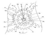
ここで、第1実施形態では、中間ギア支持軸19は、図3および図4に示すように、支持軸取付孔1eに装着される取付軸部19aと、送りローラ中間ギア13を回転可能に支持する実質的に小判形状の軸受係合部19bとを有している。この軸受係合部19bは、図7および図8に示すように、4つの支持部19d、19e、19fおよび19gと、2つのの平坦部19hおよび19iと、2つの円形状部19jおよび19kとを含む。また、4つの支持部19d〜19gは面取り形状(図7参照)、または、丸みを持った形状(図8参照)に形成されている。このように、中間ギア支持軸19の軸受係合部19bの2つの支持部19dおよび19eを面取り形状または丸みを持った形状に形成することによって、中間ギア支持軸19の軸受係合部19bの2つの支持部19dおよび19eにより送りローラ中間ギア13の円形状の軸受部13aを支持しながら送りローラ中間ギア13を回転させる場合に、送りローラ中間ギア13の軸受部13aに傷などが発生するのを抑制することが可能である。なお、この支持部19dおよび19eは、本発明の「第1支持部」の一例であり、支持部19fおよび19gは、本発明の「第2支持部」の一例である。
Here, in the first embodiment, as shown in FIGS. 3 and 4, the intermediate
また、取付軸部19aは、図3に示すように、軸受取付孔1eに取り付ける前は、均一な軸径を有している。また、取付軸部19aは、図4に示すように、かしめ加工により支持軸取付孔1eに取り付けられる。このかしめ加工により取付軸部19aの軸径が増大することによって、取付軸部19aの外周面は、支持軸取付孔1eの内周面に対して所定の押圧力で当接されている。
Further, as shown in FIG. 3, the mounting
また、図2に示すように、送りローラギア6には、送りローラギア6を回転させるための樹脂などにより形成された送りローラ中間ギア13が噛み合わされている。この送りローラ中間ギア13には、図3に示すように、円形状の軸受部13aが設けられている。また、送りローラ中間ギア13の円形状の軸受部13aには、送りローラ中間ギア13を回転可能に支持する金属製の中間ギア支持軸19の軸受係合部19bが挿入されている。また、送りローラ中間ギア13は、図2に示すように、送りローラギア6に噛み合わされる小径ギア部と、駆動伝達ギア12に噛み合わされる小径ギア部よりも大きな直径を有する大径ギア部とを備えている。また、送りローラ中間ギア13は、図3に示すように、中間ギア支持部19の軸受係合部19bに装着されるとともに、駆動伝達ギア12の大径ギア部(図2参照)と送りローラギア6の大径ギア部(図示せず)との間に挟み込まれることにより位置決めされている。また、図3に示すように、軸受係合部19bの取付軸部19aと反対側の端部近傍の外周面には、溝部19cが転造加工により形成されている。この溝部19cには、図4に示すように、抜止めワッシャ20が取り付けられている。これにより、送りローラ中間ギア13が軸受係合部19bから抜け出るのが抑制されている。また、送りローラ中間ギア13を回転させるための樹脂などにより形成された駆動伝達ギア12は、図2に示すように、送りローラ中間ギア13に噛み合わされる小径ギア部と、小径ギア部よりも大きな直径を有する大径ギア部とを備えている。この駆動伝達ギア12の大径ギア部は、駆動伝達ギア12を回転させるためのモータギア9に噛み合わされている。
Further, as shown in FIG. 2, the
また、図1に示すように、押さえローラ3の両端部は、押さえローラ3の最外周の軸径よりも小さい軸径を有するとともに、シャーシ1の側面部1bおよび1cに設けられた一対の押さえローラ軸受5により回転可能に支持されている。なお、一対の押さえローラ軸
受5は、シャーシ1の側面部1bおよび1cの内側にそれぞれ設けられた軸受支持板7に取り付けられている。この軸受支持板7は、図示しない押圧機構により押さえローラ3を送りローラ2に押圧するように構成されている。
As shown in FIG. 1, both end portions of the
また、図1に示すように、サーマルヘッド11は、サーマルヘッド支持部11aを中心に回動可能にシャーシ1の側面部1bおよび1c内部に取り付けられている。また、サーマルヘッド11は、インクシート(図示せず)および用紙(図示せず)をゴム製のプラテンローラ(図示せず)との間に挟み込むことが可能なように構成されている。また、揺動可能な中間ギア14aは、送りローラギア6に係合するとともに揺動することによってインクシート巻取りローラ(図示せず)に嵌め込まれたインクシート巻取りギア15に係合可能なように構成されている。また、複数の中間ギア14bは、送りローラギア6からの駆動力をローラ軸ギア18を介して、給排紙ローラ17が取り付けられたローラ軸16に伝達する。
As shown in FIG. 1, the
次に、図1、図2、図5および図6を参照して、第1実施形態による熱転写プリンタの動作について説明する。まず、印画時には、モータ8が駆動するのに伴ってモータギア9が矢印E方向(図2参照)に回転するので、駆動伝達ギア12と送りローラ中間ギア13とは、それぞれ図2の矢印F方向および矢印G方向に回転するとともに、送りローラギア6は、図2の矢印H方向に回転する。また、モータ8の駆動力は、送りローラギア6から中間ギア14aを介してサーマルヘッド11に伝達されるとともに、中間ギア14aからインクシート巻取りギア15を介してインクシート巻取りローラ(図示せず)に伝達される。また、モータ8の駆動力は、送りローラギア6から複数の中間ギア14bとローラ軸ギア18とを介してローラ軸16に伝達される。これにより、印画時には、サーマルヘッド11がプラテンローラ(図示せず)を押圧する方向(図1の矢印A方向)に回動されるとともに、用紙(図示せず)は、プラテンローラ(図示せず)によりサーマルヘッド11に押圧された状態で、送りローラ2および押さえローラ3によって正方向(図1の矢印C方向)に搬送される。
Next, the operation of the thermal transfer printer according to the first embodiment will be described with reference to FIG. 1, FIG. 2, FIG. 5, and FIG. First, at the time of printing, the
この際、本実施形態においては、送りローラ中間ギア13は、図5に示すように、駆動伝達ギア12から受ける力F2と、送りローラ中間ギア13を回転させる際に送りローラギア6から抗力として受ける力F3との合力として力F1を受ける。これにより、送りローラ中間ギア13の円形状の軸受部13aは、中間ギア支持軸19の軸受係合部19bの2つの支持部19dおよび19eに押圧されるので、2つの支持部19dおよび19eと送りローラ中間ギア13の軸受部13aとの間に摩擦力が働く。この摩擦力の大きさは、送りローラ中間ギア13が回転により受ける力F1の大きさが変動するのに伴って増減する。そして、摩擦力の大きさが増減することに起因して、軸受部13aの軸受係合部19bに対する接触位置を軸受係合部19bの外周面に沿って左右方向に移動させる力が働く。具体的には、力F1が増大した場合には、軸受部13aと2つの支持部19dおよび19eとの間に働く摩擦力の大きさが大きくなる。この場合には、軸受部13aの軸受係合部19bに対する接触位置を軸受係合部19bの外周面に沿って図5の矢印α方向に移動させる力が働く。その一方で、力F1が減少した場合には、軸受部13aと2つの支持部19dおよび19eとの間に働く摩擦力の大きさが小さくなる。この場合には、軸受部13aの軸受係合部19bに対する接触位置を軸受係合部19bの外周面に沿って図5の矢印β方向に移動させる力が働く。
At this time, in this embodiment, the feed roller
ここで、第1実施形態では、上記のように、中間ギア支持軸19の軸受係合部19bを実質的に小判形状に形成するとともに、その小判形状の一方の平坦部19hと円形状部19jおよび19kとの境界線上に位置する部分により構成された2つの支持部19dおよび19eを、送りローラ中間ギア13の中心を通る送りローラ中間ギア13が回転により受ける力F1の線に対して、左右に所定の角度θ1ずつ傾いた2つの位置で、送りローラ
中間ギア13の円形状の軸受部13aを支持するように配置することによって、送りローラ中間ギア13の軸受部13aを中間ギア支持軸19の軸受係合部19bの周面の1箇所で支持する場合に比べて、送りローラ中間ギア13の軸受部13aが中間ギア支持軸19の軸受係合部19bの外周面に沿って移動しにくくなる。このため、送りローラ中間ギア13が回転により受ける力F1の変動により送りローラ中間ギア13の軸受部13aと中間ギア支持軸19の2つの支持部19dおよび19eとの間に働く摩擦力F1の大きさが変動(増減)することに起因して、軸受部13aの軸受係合部19bに対する接触位置を軸受係合部19bの外周面に沿って左右方向に移動させる力が働いた場合にも、送りローラ中間ギア13の軸受部13aの軸受係合部19bに対する接触位置が、軸受係合部19bの外周面に沿って左右方向に移動するのを抑制することができる。これにより、送りローラ中間ギア13の回転量の変動が生じるのを抑制することができるので、送りローラ中間ギア13の回転量の変動に起因して送りローラギア6の回転量の変動が発生するのを抑制することができる。その結果、印画時に、送りローラ2による用紙の送りムラを抑制することができるので、用紙の搬送を精度良く制御することが可能となるとともに、印画品質を向上させることが可能となる。また、中間ギア支持軸19の軸受係合部19bを実質的に小判形状にするだけでよいので、部品の精度を上げる必要もない。
Here, in the first embodiment, as described above, the
また、非印画時の逆方向(図1のD方向)への用紙搬送時には、モータ8が逆方向に回転するのに伴ってモータギア9が矢印I方向(図2参照)に回転するので、駆動伝達ギア12と送りローラ中間ギア13とは、それぞれ図2の矢印J方向および矢印K方向に回転するとともに、送りローラギア6は、図2の矢印L方向に回転する。また、揺動可能な中間ギア14aは、インクシート巻取りギア15には係合しないので、インクシート巻取りローラ(図示せず)は回転しない。このとき、サーマルヘッド11は、プラテンローラ(図示せず)から離間する方向(図1の矢印B方向)に回動されるとともに、用紙(図示せず)は、サーマルヘッド11に押圧されない状態で送りローラ2および押さえローラ3によって逆方向(図1の矢印D方向)に搬送される。
Further, when the paper is conveyed in the reverse direction (D direction in FIG. 1) during non-printing, the
この際、送りローラ中間ギア13は、図6に示すように、駆動伝達ギア12から受ける力F5と、送りローラ中間ギア13を回転させる際に送りローラギア6から抗力として受ける力F6との合力として力F4を受ける。これにより、送りローラ中間ギア13の円形状の軸受部13aは、中間ギア支持軸19の軸受係合部19bの2つの支持部19fおよび19gに押圧されるので、2つの支持部19fおよび19gと送りローラ中間ギア13の軸受部13aとの間に摩擦力が働く。この摩擦力の大きさは、送りローラ中間ギア13が回転により受ける力F4の大きさが変動するのに伴って増減する。そして、摩擦力の大きさが増減することに起因して、軸受部13aの軸受係合部19bに対する接触位置を軸受係合部19bの外周面に沿って左右方向に移動させる力が働く。具体的には、力F4が増大した場合には、軸受部13aと2つの支持部19fおよび19gとの間に働く摩擦力の大きさが大きくなる。この場合には、軸受部13aの軸受係合部19bに対する接触位置を軸受係合部19bの外周面に沿って図6の矢印γ方向に移動させる力が働く。その一方で、力F1が減少した場合には、軸受部13aと2つの支持部19dおよび19eとの間に働く摩擦力の大きさが小さくなる。この場合には、軸受部13aの軸受係合部19bに対する接触位置を軸受係合部19bの外周面に沿って図6の矢印δ方向に移動させる力が働く。
At this time, as shown in FIG. 6, the feed roller
この場合も、第1実施形態では、中間ギア支持軸19の軸受係合部19bを実質的に小判形状に形成するとともに、その小判形状の一方の平坦部19iと円形状部19jおよび19kとの境界線上に位置する部分により構成された2つの支持部19fおよび19gを、送りローラ中間ギア13の中心を通る送りローラ中間ギア13が回転により受ける力F4の線に対して、左右に所定の角度θ2ずつ傾いた2つの位置で、送りローラ中間ギア13の円形状の軸受部13aを支持するように配置することによって、送りローラ中間ギア
13の軸受部13aを中間ギア支持軸19の軸受係合部19bの周面の1箇所で支持する場合に比べて、送りローラ中間ギア13の軸受部13aが中間ギア支持軸19の軸受係合部19bの外周面に沿って移動しにくくなる。このため、送りローラ中間ギア13が回転により受ける力F4の変動により送りローラ中間ギア13の軸受部13aと中間ギア支持軸19の2つの支持部19fおよび19gとの間に働く摩擦力F4の大きさが変動(増減)することに起因して、軸受部13aの軸受係合部19bに対する接触位置を軸受係合部19bの外周面に沿って左右方向に移動させる力が働いた場合にも、送りローラ中間ギア13の軸受部13aの軸受係合部19bに対する接触位置が、軸受係合部19bの外周面に沿って左右方向に移動するのを抑制することができる。これにより、送りローラ中間ギア13の回転量の変動が生じるのを抑制することができるので、送りローラ中間ギア13の回転量の変動に起因して送りローラギア6の回転量の変動が発生するのを抑制することができる。その結果、非印画時に、送りローラ2による用紙の送りムラを抑制することができるので、用紙の搬送を精度良く制御することが可能となる。
Also in this case, in the first embodiment, the
第1実施形態では、上記のように、中間ギア支持軸19の軸受係合部19bを、2つの平坦部19hおよび19iを有する小判形状に形成することによって、送りローラ中間ギア13が正方向および逆方向に回転する場合に、回転方向に応じて、両方の平坦部19hおよび19iを支持部として用いることが可能である。
In the first embodiment, as described above, the
図9〜図11は、本発明の第1実施形態による熱転写プリンタに用いる中間ギア支持軸の製造方法を説明するための図である。次に、図9〜図11を参照して、第1実施形態による熱転写プリンタの中間ギア支持軸の製造方法について説明する。 FIGS. 9-11 is a figure for demonstrating the manufacturing method of the intermediate gear support shaft used for the thermal transfer printer by 1st Embodiment of this invention. Next, a method for manufacturing the intermediate gear support shaft of the thermal transfer printer according to the first embodiment will be described with reference to FIGS.
第1実施形態による中間ギア支持軸19の製造方法では、概略的には、図9に示すように、金型30aおよび30bを含むヘッダ装置30を用いて金属棒190を鍛造加工することにより中間ギア支持軸19(図11参照)を形成する。この際、第1実施形態では、ヘッダ装置30の受け側(キャビティ側)の金型30a内において、中間ギア支持軸19を一体的に形成する。この金型30aには、図10に示すように、中間ギア支持軸19の取付軸19aおよび軸受係合部19bを形成するための円形状の孔部および小判形状の孔部が設けられている。具体的な製造方法としては、まず、受け側の金型30aを備えたヘッダ装置30を準備する。そして、そのヘッダ装置30の受け側の金型30a内に金属棒190を配置する。そして、図11に示すように、ヘッダ装置30のハンマ側の金型30bを下降させて金属棒190に加圧することによって、金属棒190を中間ギア支持軸19の形状に変形させる。この後、ハンマ側の金型30bを上昇させた後、受け側の金型30aから中間ギア支持軸19を取り出す。これにより、金型30aの孔部に対応する2つの平坦部19hおよび19iを有する小判形状の軸受係合部19bと、取付軸部19aとを含む中間ギア支持軸19が形成される。この後、軸受係合部19bの取付軸部19aと反対側の端部近傍の外周面に転造加工により溝部19c(図3参照)を形成する。上記のようにして、図3に示した第1実施形態による中間ギア支持軸19が形成される。
In the manufacturing method of the intermediate
図12〜図14は、本発明の第1実施形態による熱転写プリンタの中間ギア支持軸のシャーシに対する取付けプロセスを説明するための図である。次に、図12〜図14を参照して、第1実施形態による熱転写プリンタの中間ギア支持軸の取付けプロセスについて説明する。 12 to 14 are views for explaining an attachment process of the intermediate gear support shaft to the chassis of the thermal transfer printer according to the first embodiment of the present invention. Next, with reference to FIGS. 12 to 14, a process for attaching the intermediate gear support shaft of the thermal transfer printer according to the first embodiment will be described.
この第1実施形態による中間ギア支持軸19の取付プロセスでは、図12に示すように、シャーシ1の側面部1cの支持軸取付孔1eに中間ギア支持軸19の取付軸部19aを挿入するとともに、中間ギア支持軸19の軸受係合部19b側を治具40(図13参照)の軸保持孔40aによって保持する。この軸保持孔40aは、図13に示すように、軸受係合部19bに対応する小判形状に形成されている。この場合、治具40の小判形状の軸
保持孔40aの平坦部に、軸受係合部19bの2つの平坦部19hおよび19i(図12参照)を嵌め込むによって、中間ギア支持軸19の角度位置の位置決めを行う。そして、支持軸取付孔1eから突出した取付軸部19aの端部をハンマ41により叩くことによって、かしめ加工を行う。これにより、図14に示すように、取付軸部19aの端部(かしめ部)の外径が大きくなるので、取付軸部19aが支持軸取付孔1eに固定される。この際、取付軸部19aの軸径が増大することによって、取付軸部19aの外周面が支持軸取付孔1eの内周面に所定の押圧力で当接される。
In the attachment process of the intermediate
(第2実施形態)
図15は、本発明の第2実施形態による熱転写プリンタの中間ギア支持軸の取付構造を示した分解斜視図である。図16は、図15に示した第2実施形態による熱転写プリンタの中間ギア支持軸の取付構造を示した断面図である。図17は、図15に示した第2実施形態による熱転写プリンタの中間ギア支持軸を示した平面図である。この第2実施形態では、上記第1実施形態と異なり、中間ギア支持軸の軸受係合部と取付軸部との間に、軸受係合部よりも大きな外径を有するとともに、軸受係合部の小判形状よりも大きい小判形状の平坦部を有する座部をさらに設けた例について説明する。なお、中間ギア支持軸の構造、製造方法および取付プロセス以外は上記第1実施形態と同様であるので、その説明を省略する。
(Second Embodiment)
FIG. 15 is an exploded perspective view showing an attachment structure for an intermediate gear support shaft of a thermal transfer printer according to the second embodiment of the present invention. FIG. 16 is a cross-sectional view showing an attachment structure of an intermediate gear support shaft of the thermal transfer printer according to the second embodiment shown in FIG. FIG. 17 is a plan view showing an intermediate gear support shaft of the thermal transfer printer according to the second embodiment shown in FIG. Unlike the first embodiment, the second embodiment has a larger outer diameter than the bearing engaging portion between the bearing engaging portion and the mounting shaft portion of the intermediate gear support shaft, and the bearing engaging portion. An example in which a seat portion having a flat portion having an oval shape larger than the oval shape will be described. In addition, since it is the same as that of the said 1st Embodiment except the structure of a middle gear support shaft, a manufacturing method, and an attachment process, the description is abbreviate | omitted.
第2実施形態による熱転写プリンタでは、中間ギア支持軸69は、図15〜図17に示すように、シャーシ1の支持軸取付孔1eに装着される取付軸部69aと、送りローラ中間ギア13を回転可能に支持する実質的に小判形状の軸受係合部69bと、座部69lとを有している。この軸受係合部69bは、図17に示すように、4つの支持部69d、69e、69fおよび69gと、2つのの平坦部69hおよび69iと、2つの円形状部69jおよび69kとを含む。なお、この支持部69dおよび69eは、本発明の「第1支持部」の一例であり、支持部69fおよび69gは、本発明の「第2支持部」の一例である。また、座部69lは、軸受係合部69bと取付軸部69aとの間に設けられている。また、この座部69lは、軸受係合部69bよりも大きな外径を有するとともに、軸受係合部69bの小判形状よりも大きい小判形状の平坦部69mおよび69nを有する。
In the thermal transfer printer according to the second embodiment, as shown in FIGS. 15 to 17, the intermediate
図18〜図21は、本発明の第2実施形態による熱転写プリンタに用いる中間ギア支持軸の製造方法を説明するための図である。次に、図18〜図21を参照して、第2実施形態による熱転写プリンタの中間ギア支持軸の製造方法について説明する。 18 to 21 are views for explaining a method of manufacturing the intermediate gear support shaft used in the thermal transfer printer according to the second embodiment of the present invention. Next, a method for manufacturing the intermediate gear support shaft of the thermal transfer printer according to the second embodiment will be described with reference to FIGS.
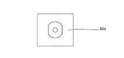
第2実施形態による中間ギア支持軸69の製造方法では、概略的には、図20に示すように、金型85aおよび85bを含むヘッダ装置85を用いて金属棒169を鍛造加工することにより中間ギア支持軸69(図21参照)を形成する。この際、第2実施形態では、ヘッダ装置85の受け側(キャビティ側)の金型85a内とハンマ側の金型85b内とにおいて、中間ギア支持軸69を一体的に形成する。この金型85bには、図18に示すように、中間ギア支持軸69の軸受係合部69bを形成するための小判形状の孔部が設けられている。また、この金型85aには、図19に示すように、中間ギア支持軸69の取付軸部69aおよび座部69lを形成するための円形状の孔部および小判形状の孔部が設けられている。具体的な製造方法としては、受け側の金型85aとハンマ側の金型85bとを備えたヘッダ装置85を準備する。次に、そのヘッダ装置85の受け側の金型85a内に金属棒169を配置する。そして、図21に示すように、ヘッダ装置85のハンマ側の金型85bを下降させて金属棒169に加圧することによって、金属棒169を中間ギア支持軸69の形状に変形させる。この後、ハンマ側の金型85bを上昇させた後、受け側の金型85aから中間ギア支持軸69を取り出す。これにより、図21に示すように、金型85aの孔部に対応する2つの平坦部69hおよび69iを有する小判形状の軸受係合部69bと2つの平坦部69mおよび69nを有する小判形状の座部69lと取付軸部
69aとを含む中間ギア支持軸69が形成される。この後、中間ギア支持軸69の取付軸部69aと反対側の端部近傍の外周面に、転造加工により溝部69c(図15参照)を形成する。上記のようにして、図15に示した第2実施形態による中間ギア支持軸69が形成される。
In the manufacturing method of the intermediate
図22〜図24は、本発明の第2実施形態による熱転写プリンタの中間ギア支持軸の取付けプロセスを説明するための図である。次に、図22〜図24を参照して、第2実施形態による熱転写プリンタの中間ギア支持軸の取付けプロセスについて説明する。 22 to 24 are views for explaining an attachment process of the intermediate gear support shaft of the thermal transfer printer according to the second embodiment of the present invention. Next, with reference to FIGS. 22 to 24, a process for mounting the intermediate gear support shaft of the thermal transfer printer according to the second embodiment will be described.
この第2実施形態による中間ギア支持軸69の取付プロセスでは、図22に示すように、シャーシ1の側面部1cの支持軸取付孔1eに中間ギア支持軸69の取付軸部69aを挿入するとともに、中間ギア支持軸69の軸受係合部69b側を治具90の軸保持孔90aによって保持する。この軸保持孔90aは、図23に示すように、座部69lおよび軸受取付孔69bに対応する小判形状に形成されている。この場合、治具90の座部69lに対応する小判形状の軸保持孔90aの平坦部に、座部69lの2つの平坦部69mおよび69n(図22参照)を嵌め込むことによって、中間ギア支持軸69の角度位置の位置決めを行う。そして、支持軸取付孔1eから突出した取付軸部69aの端部をハンマ91により叩くことによって、かしめ加工を行う。これにより、図24に示すように、取付軸部69aの端部(かしめ部)の外径が大きくなるので、取付軸部69aが支持軸取付孔1eに固定される。この際、取付軸部69aの軸径が増大することによって、取付軸部69aの外周面が支持軸取付孔1eの内周面に所定の押圧力で当接される。
In the attachment process of the intermediate
第2実施形態では、上記のように、中間ギア支持軸69には、シャーシ1の支持軸取付
孔1eにかしめ加工により取り付けられる取付軸部69aと、取付軸部69aと軸受係合部69bとの間に設けられ、軸受係合部69bよりも大きい外径を有するとともに、軸受係合部69bの小判形状よりも大きい小判形状の平坦部69mおよび69nを有する座部69lとを設けることによって、シャーシ1の支持軸取付孔1eに取付軸部19aをかし
め加工により取り付ける際に、軸受係合部69bの小判形状の平坦部69hおよび69iを用いて中間ギア支持軸69の角度位置の位置決めを行う場合に比べて、座部の小判形状の平坦部69mおよび69nを用いて中間ギア支持軸69の角度位置の位置決めを行う方が、より大きな平坦面を基準に位置決めを行うことができるので、中間ギア支持軸69の小判形状の平坦部69hおよび69iの回転角度位置をより正確に位置決めすることができる。
In the second embodiment, as described above, the intermediate
なお、第2実施形態のその他の効果は上記第1実施形態と同様である。 The remaining effects of the second embodiment are similar to those of the aforementioned first embodiment.
なお、今回開示された実施形態は、すべての点で例示であって制限的なものではないと考えられるべきである。本発明の範囲は、上記した実施形態の説明ではなく特許請求の範囲によって示され、さらに特許請求の範囲と均等の意味および範囲内でのすべての変更が含まれる。 The embodiment disclosed this time should be considered as illustrative in all points and not restrictive. The scope of the present invention is shown not by the above description of the embodiments but by the scope of claims for patent, and further includes all modifications within the meaning and scope equivalent to the scope of claims for patent.
たとえば、上記実施形態では、画像形成装置の一例として熱転写プリンタを示したが、本発明はこれに限らず、送りローラを有する画像形成装置であれば、熱転写プリンタ以外の他の画像形成装置にも適用可能である。 For example, in the above embodiment, a thermal transfer printer is shown as an example of an image forming apparatus. However, the present invention is not limited to this, and any image forming apparatus other than the thermal transfer printer may be used as long as the image forming apparatus has a feed roller. Applicable.
また、上記実施形態では、座部を小判形状に形成した例を示したが、本発明はこれに限らず、座部を軸受係合部よりも大きい平坦部を有するDカット形状に形成してもよい。 Moreover, although the example which formed the seat part in the oval shape was shown in the said embodiment, this invention is not limited to this, The seat part is formed in D cut shape which has a flat part larger than a bearing engaging part. Also good.
13 送りローラ中間ギア(中間ギア)
13a 軸受部
19 中間ギア支持軸
19d 支持部(第1支持部)
19e 支持部(第1支持部)
19h 平坦部
19i 平坦部
19j 円形状部
19k 円形状部
69l 座部
69d 支持部(第1支持部)
69e 支持部(第1支持部)
13 Feed roller intermediate gear (intermediate gear)
19e support part (1st support part)
19h
69e support part (first support part)
Claims (7)
前記中間ギア支持軸は、前記中間ギアの軸受部に挿入され、平坦部と円形状部とを有する実質的に小判形状の断面形状を含む軸受係合部を含み、
前記中間ギア支持軸の実質的に小判形状の軸受係合部は、一方の前記平坦部と前記円形状部との境界線上に位置する部分により構成された2つの支持部を含み、
前記2つの支持部は、前記中間ギアの中心を通る前記中間ギアが回転により受ける力の線に対して、左右に所定の角度ずつ傾いた2つの位置で、前記中間ギアの円形状の軸受部を支持するように配置されており、
前記2つの支持部は、面取りまたは丸みを持った形状を有している、画像形成装置。 A feed roller for transporting a sheet of paper that rotates about a rotation axis; a pressing roller that presses the sheet against the feed roller; a feed roller gear provided on the rotation axis of the feed roller; and a circular bearing portion , An intermediate gear for rotating the feed roller gear, a drive transmission gear for rotating the intermediate gear as the motor is driven, and a circular bearing portion of the intermediate gear for rotation In an image forming apparatus provided with an intermediate gear support shaft supported by
The intermediate gear support shaft includes a bearing engagement portion that is inserted into a bearing portion of the intermediate gear and includes a substantially oval cross-sectional shape having a flat portion and a circular portion,
The substantially oval bearing engagement portion of the intermediate gear support shaft includes two support portions constituted by a portion located on a boundary line between the one flat portion and the circular portion,
The two support portions are circular bearing portions of the intermediate gear at two positions inclined by a predetermined angle to the left and right with respect to a line of force received by rotation of the intermediate gear passing through the center of the intermediate gear. Is arranged to support
The image forming apparatus, wherein the two support portions have a chamfered shape or a rounded shape.
円形状の軸受部を含み、前記送りローラギアを回転させるギアと、
モータの駆動に伴って前記ギアを回転させる駆動伝達ギアと、
前記ギアを回転可能に支持するギア支持軸とを備え、
前記ギア支持軸は、前記ギアの軸受部に挿入され、平坦部と円形状部とを有する実質的に小判形状を有する軸受係合部を含み、
前記軸受係合部は、前記小判形状の平坦部と、前記円形状部との境界線上に位置する部分により構成された2つの支持部を含み、
前記2つの支持部の少なくとも一方は、前記ギアの中心を通る前記ギアが回転により受ける力の線に対して所定の角度傾いた位置で、前記ギアの円形状の軸受部を支持するように配置されている、画像形成装置。 A feed roller gear provided on a feed roller for conveying paper;
A gear including a circular bearing and rotating the feed roller gear;
A drive transmission gear for rotating the gear as the motor is driven;
A gear support shaft that rotatably supports the gear;
The gear support shaft includes a bearing engagement portion that is inserted into a bearing portion of the gear and has a substantially oval shape having a flat portion and a circular portion,
The bearing engaging portion includes two support portions configured by a portion located on a boundary line between the oval flat portion and the circular portion,
At least one of the two support portions is arranged to support the circular bearing portion of the gear at a position inclined at a predetermined angle with respect to a line of force that the gear passing through the center of the gear receives by rotation. An image forming apparatus.
前記ギア支持軸は、前記シャーシの支持軸取付孔にかしめ加工により取り付けられる取付軸部と、前記取付軸部と前記軸受係合部との間に設けられ、前記軸受係合部よりも大きい外径を有するとともに、前記軸受係合部の小判形状よりも大きい小判形状の平坦部を有する座部とをさらに含む、請求項2〜5のいずれか1項に記載の画像形成装置。 A chassis having a support shaft mounting hole for mounting the gear support shaft;
The gear support shaft is provided between a mounting shaft portion attached to the support shaft mounting hole of the chassis by caulking, and between the mounting shaft portion and the bearing engaging portion, and is larger than the outer surface of the bearing engaging portion. 6. The image forming apparatus according to claim 2, further comprising a seat portion having a diameter and a flat portion having an oval shape larger than the oval shape of the bearing engaging portion.
前記軸受係合部の支持部は、前記小判形状の一方の前記平坦部と前記円形状部との境界線上に位置する部分により構成された2つの第1支持部と、前記小判形状の他方の前記平坦部と前記円形状部との境界線上に位置する部分により構成された2つの第2支持部とを含み、
前記2つの第1支持部は、前記ギアが正方向に回転する際に、前記ギアの中心を通る前記ギアが正方向の回転により受ける力の線に対して、左右に所定の角度ずつ傾いた2つの位置で、前記ギアの円形状の軸受部を支持するように配置されており、
前記2つの第2支持部は、前記ギアが逆方向に回転する際に、前記ギアの中心を通る前記ギアが逆方向の回転により受ける力の線に対して、左右に所定の角度ずつ傾いた2つの位置で、前記ギアの円形状の軸受部を支持するように配置されている、請求項2〜6のいずれか1項に記載の画像形成装置。 The gear is rotated in the forward and reverse directions;
The support portion of the bearing engaging portion includes two first support portions configured by portions located on a boundary line between one flat portion of the oval shape and the circular portion, and the other oval shape of the oval shape. Including two second support portions configured by portions located on a boundary line between the flat portion and the circular portion,
When the gear rotates in the forward direction, the two first support portions are inclined at a predetermined angle to the left and right with respect to a line of force that the gear passing through the center of the gear receives by rotation in the forward direction. It is arranged to support the circular bearing of the gear at two positions,
When the gear rotates in the reverse direction, the two second support portions are inclined at a predetermined angle to the left and right with respect to a line of force that the gear passing through the center of the gear receives by the reverse rotation. The image forming apparatus according to claim 2, wherein the image forming apparatus is disposed so as to support a circular bearing portion of the gear at two positions.
Priority Applications (2)
| Application Number | Priority Date | Filing Date | Title |
|---|---|---|---|
| JP2004218119A JP3811954B2 (en) | 2004-07-27 | 2004-07-27 | Image forming apparatus |
| US11/184,875 US7354212B2 (en) | 2004-07-27 | 2005-07-20 | Image forming apparatus |
Applications Claiming Priority (1)
| Application Number | Priority Date | Filing Date | Title |
|---|---|---|---|
| JP2004218119A JP3811954B2 (en) | 2004-07-27 | 2004-07-27 | Image forming apparatus |
Publications (2)
| Publication Number | Publication Date |
|---|---|
| JP2006035613A JP2006035613A (en) | 2006-02-09 |
| JP3811954B2 true JP3811954B2 (en) | 2006-08-23 |
Family
ID=35730991
Family Applications (1)
| Application Number | Title | Priority Date | Filing Date |
|---|---|---|---|
| JP2004218119A Expired - Fee Related JP3811954B2 (en) | 2004-07-27 | 2004-07-27 | Image forming apparatus |
Country Status (2)
| Country | Link |
|---|---|
| US (1) | US7354212B2 (en) |
| JP (1) | JP3811954B2 (en) |
Families Citing this family (3)
| Publication number | Priority date | Publication date | Assignee | Title |
|---|---|---|---|---|
| JP5754945B2 (en) | 2011-01-05 | 2015-07-29 | キヤノン株式会社 | Recording device and rotating body support device |
| JP6184201B2 (en) * | 2013-06-28 | 2017-08-23 | キヤノン株式会社 | Paper feeding device and image forming apparatus having the same |
| JP6634098B2 (en) | 2015-06-30 | 2020-01-22 | サン−ゴバン パフォーマンス プラスティックス コーポレイション | Sliding bearing |
Family Cites Families (3)
| Publication number | Priority date | Publication date | Assignee | Title |
|---|---|---|---|---|
| JPS53147165A (en) * | 1977-05-27 | 1978-12-21 | Hitachi Ltd | Gear device for pulsometor for washing machine |
| JPH0942422A (en) | 1995-08-03 | 1997-02-14 | Fuji Elelctrochem Co Ltd | Resin made gear |
| JPH11262959A (en) | 1998-03-17 | 1999-09-28 | Ricoh Co Ltd | Toothed rotation transmitting member by plastic molding |
-
2004
- 2004-07-27 JP JP2004218119A patent/JP3811954B2/en not_active Expired - Fee Related
-
2005
- 2005-07-20 US US11/184,875 patent/US7354212B2/en not_active Expired - Fee Related
Also Published As
| Publication number | Publication date |
|---|---|
| JP2006035613A (en) | 2006-02-09 |
| US20060022010A1 (en) | 2006-02-02 |
| US7354212B2 (en) | 2008-04-08 |
Similar Documents
| Publication | Publication Date | Title |
|---|---|---|
| US20020135122A1 (en) | Image recording apparatus | |
| JP2001240275A (en) | Sheet material conveying device and recording device | |
| JP4572713B2 (en) | Image forming apparatus | |
| US20070291100A1 (en) | Print head assmebly and method used with image forming apparatus | |
| JP3811954B2 (en) | Image forming apparatus | |
| JP2008114415A (en) | Thermal transfer line printer | |
| US7597321B2 (en) | Image forming apparatus | |
| JP3885969B2 (en) | Image forming apparatus | |
| JP3951306B2 (en) | Image forming apparatus | |
| JP3882934B2 (en) | Image forming apparatus | |
| JP4952929B2 (en) | Power transmission device, power transmission device assembly method and recording device | |
| JP3811952B2 (en) | Image forming apparatus | |
| JP3891439B2 (en) | Thermal transfer printer and image forming apparatus | |
| JP2006111403A (en) | Image forming device | |
| JP2005041070A (en) | Thermal transfer printer | |
| JP3921689B2 (en) | Image forming apparatus | |
| JP4045450B2 (en) | Image forming apparatus | |
| JP2016172610A (en) | Transport device and printer | |
| JP2007106060A (en) | Printer apparatus | |
| JP3759123B2 (en) | Paper feeder | |
| JP4434152B2 (en) | Image forming apparatus | |
| US7922406B2 (en) | Image generating apparatus | |
| JP3919118B2 (en) | Image forming apparatus | |
| JP4735433B2 (en) | Image forming apparatus | |
| JPH08174944A (en) | Paper feed device for printer |
Legal Events
| Date | Code | Title | Description |
|---|---|---|---|
| A977 | Report on retrieval |
Free format text: JAPANESE INTERMEDIATE CODE: A971007 Effective date: 20060426 |
|
| TRDD | Decision of grant or rejection written | ||
| A01 | Written decision to grant a patent or to grant a registration (utility model) |
Free format text: JAPANESE INTERMEDIATE CODE: A01 Effective date: 20060508 |
|
| A61 | First payment of annual fees (during grant procedure) |
Free format text: JAPANESE INTERMEDIATE CODE: A61 Effective date: 20060521 |
|
| R150 | Certificate of patent or registration of utility model |
Free format text: JAPANESE INTERMEDIATE CODE: R150 |
|
| FPAY | Renewal fee payment (event date is renewal date of database) |
Free format text: PAYMENT UNTIL: 20100609 Year of fee payment: 4 |
|
| FPAY | Renewal fee payment (event date is renewal date of database) |
Free format text: PAYMENT UNTIL: 20110609 Year of fee payment: 5 |
|
| FPAY | Renewal fee payment (event date is renewal date of database) |
Free format text: PAYMENT UNTIL: 20110609 Year of fee payment: 5 |
|
| FPAY | Renewal fee payment (event date is renewal date of database) |
Free format text: PAYMENT UNTIL: 20120609 Year of fee payment: 6 |
|
| FPAY | Renewal fee payment (event date is renewal date of database) |
Free format text: PAYMENT UNTIL: 20120609 Year of fee payment: 6 |
|
| FPAY | Renewal fee payment (event date is renewal date of database) |
Free format text: PAYMENT UNTIL: 20130609 Year of fee payment: 7 |
|
| LAPS | Cancellation because of no payment of annual fees |