JP3811139B2 - Earrings - Google Patents
Earrings Download PDFInfo
- Publication number
- JP3811139B2 JP3811139B2 JP2003127370A JP2003127370A JP3811139B2 JP 3811139 B2 JP3811139 B2 JP 3811139B2 JP 2003127370 A JP2003127370 A JP 2003127370A JP 2003127370 A JP2003127370 A JP 2003127370A JP 3811139 B2 JP3811139 B2 JP 3811139B2
- Authority
- JP
- Japan
- Prior art keywords
- catch
- mounting pin
- ear
- peripheral wall
- support
- Prior art date
- Legal status (The legal status is an assumption and is not a legal conclusion. Google has not performed a legal analysis and makes no representation as to the accuracy of the status listed.)
- Expired - Lifetime
Links
Images


Landscapes
- Adornments (AREA)
Description
【0001】
【発明の属する技術分野】
本発明は、ピアスの改良に関するものである。
【0002】
【従来の技術】
ピアスは、よく知られているように、貴金属や宝石などによって構成された装飾体を取付ピンの一端に取付けると共に、該取付ピンの他端を通常耳たぶに設けた孔に挿通し、耳の後側(裏側)でキャッチで止めるようになっている。
また、図3に示すように、耳の表側に取付けられる第1の装飾体110のほかに、耳の裏側に第2の装飾体120が取付けられ、該装飾体120は第1の装飾体110が一端に取付けられた取付ピン112の他端側に取付けられたL字状の支持ピン122の一端に取付けられ、該支持ピン122の他端には上記取付ピン112を挿通するための複数の位置決め穴124,126,128が設けられ、上記取付ピン112の他端近傍に設けた溝114にキャッチ116を係止させたピアスは従来公知(例えば、特許文献1参照)である。
【0003】
しかし、上記従来公知のピアスは、第1の装飾体110が一端に取付けられた取付ピン112と、第2の装飾体120が取付けられたL字状の支持ピン122と、上記取付ピン112の他端を係止するキャッチ116の3つの部品で構成されるため、部品点数が多く、装着・脱着が不便であった。
また、上記取付ピン112の他端近傍に設けた溝114にキャッチ116を係止させているため、上記取付ピン112の軸方向におけるキャッチ116の係止位置は常に溝114の位置であり、キャッチ116の係止位置を自由に変えることはできなかった。
また、L字状の支持ピン122は、取付ピン112の他端側にぶら下がった状態で取付けられるため、第2の装飾体120は耳たぶの下部にしか飾ることができなかった。
【0004】
【特許文献1】
特開2001−149119号公報
【0005】
【発明が解決しようとする課題】
本発明の課題は、このような問題を解決し、耳の裏側から取付けられる第2の飾体を有するものでありながら部品点数が少なく、装着・脱着が簡単なピアスを提供することにある。
本発明の他の課題は、第2の飾体を耳の下部だけでなく耳の横位置にも飾ることができるピアスを提供することにある。
更に、本発明の他の課題は、見た人に意外性を感じさせることができるピアスを提供することにある。
更に、本発明の他の課題は、手持ちの別のピアス本体も使用可能なピアスを提供することにある。
【0006】
【課題を解決するための手段】
上記課題を解決するための本発明のピアスは、取付ピンの一端に第1の飾体を設けたピアス本体と、該取付ピンに嵌着するキャッチとからなるピアスにおいて、上記キャッチが、上記取付ピンが挿入・嵌着されるキャッチ本体と、該キャッチ本体に一体的に突出して設けられると共にその先端に第2の飾体を固定した支持体とを有し、上記キャッチ本体が、上記取付ピンの直径よりも小径で上記取付ピンが挿入される挿通孔を有するシリコンゴム体をその内部に有し、該シリコンゴム体と上記取付ピンとの摩擦力によって上記取付ピンをその挿入位置で上記キャッチ本体に嵌着可能にし、上記キャッチ本体が、上記シリコンゴム体を収納する空間及び該空間を囲む蓋部、周壁部、底壁部を備えた筒状体を有し、蓋部と周壁部とは別体に形成して結合され、底壁部は周壁部と一体に形成されており、該蓋部が上記取付ピンが挿入される挿通孔及び上記取付ピンを該挿通孔に案内するテーパ状の案内部を有し、該筒状体の周壁部に上記支持体が一体的に設けられ、かつ支持体は筒状体の周壁部から半径方向に突出することを特徴とするものである。
【0007】
上記本発明のピアスの好ましい実施の形態においては、上記ピアスを耳に装着した時に、上記第2の飾体だけが耳の周囲から見えるように、上記支持体の長さを丁度耳の後ろに隠れるような長さに形成される。
【0008】
上記ピアスは、キャッチ本体に一体的に突出して設けられた支持体の先端に第2の飾体を設けているため、耳の表側に取付けられる第1の飾体のほかに、耳の裏側から取付けられる第2の飾体を有するものでありながら、ピアスの部品点数を減少させることができる。
また、部品点数を減少したことと、ピアスを装着・脱着する際に上記支持体を把持部材として利用できることにより、ピアスの装着・脱着が従来のものより簡単になる。
【0009】
また、上記ピアスは、キャッチ本体が、取付ピンの直径よりも小径で取付ピンが挿入される挿通孔を有するシリコンゴム体をその内部に有しているため、該シリコンゴム体と上記取付ピンとの摩擦力によって上記取付ピンをその挿入位置で上記キャッチ本体に係止させることができる。
したがって、取付ピンの先端に第1の飾体を設けたピアス本体を耳たぶの通し穴に挿通した後、キャッチ本体を上記取付ピンに挿入し、キャッチ本体を回動させて第2の飾体が耳たぶの周囲の好みの位置に来た時点でキャッチ本体を耳たぶ側に押し付けるか、または、キャッチ本体を耳たぶに押し付ける位置まで挿入してから、第2の飾体が耳たぶの周囲の好みの位置に来るようにキャッチ本体を回動させると、キャッチ本体をこの回動位置で耳たぶに取付けることができる。
【0010】
そして、上記ピアスはキャッチ本体を回動させた位置で耳に取付けることができるため、第2の飾体を耳の下部だけでなく耳の横位置でも飾ることができる。
また、上記ピアスを耳に装着した時に、第2の飾体だけが耳の周囲から見えるように、支持体の長さを丁度耳の後ろに隠れるような長さにすると、見た人に第2の飾体がなににも支持されていないのに耳の周囲にあるという意外性を感じさせることができる。
【0011】
また、上記シリコンゴム体は弾性を有するため、挿通孔が取付ピンの直径より小径でも取付ピンを挿通孔に挿入でき、また、取付ピンの直径が多少大きかったり小さくても取付ピンをシリコンゴム体の挿通孔に挿入・係止でき、そのために手持ちの別のピアス本体を用いることもできる。
また、上記キャッチ本体が、上記シリコンゴム体を収納する空間及び該空間を囲む蓋部、周壁部、底壁部を備えた筒状体を有し、該蓋部が上記取付ピンが挿入される挿通孔及び上記取付ピンを該挿通孔に案内するテーパ状の案内部を有し、該筒状体の周壁部に上記支持体が一体的に設けられていると、支持体を把持部として利用できると共にピアス本体の取付ピンをキャッチ本体の挿通孔に容易に挿入できる。
【0012】
【発明の実施の形態】
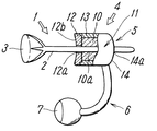
図1は、本発明に係るピアスの一実施例を示す一部断面側面図である。
該ピアスは、取付ピン2の一端に第1の飾体3を設けたピアス本体1と、該取付ピン2を係止するキャッチ4とから成り、該キャッチ4は上記取付ピン2が挿入・係止されるキャッチ本体5と、該キャッチ本体5に一体的に突出して設けられると共にその先端に第2の飾体7を設けた支持体6とを有している。
【0013】
上記キャッチ本体5は、取付ピン2の直径よりも小径で取付ピン2が挿入される挿通孔10aを有する筒状のシリコンゴム体10と、該シリコンゴム体10を収納する空間をその内部に備えた筒状体11とを有し、該筒状体11は蓋部12、周壁部13及び底壁部14を備え、これらの部材で囲まれた空間に該シリコンゴム体10が隙間が生じないようにきつめに収納されている。
上記蓋部12は上記周壁部13と別体であるが、螺着、嵌着またはその他の周知の固着手段により両者は一体的に結合されており、上記底壁部14は上記周壁部13に一体に形成されている。
【0014】
また、上記筒蓋部12は、上記取付ピン2が挿入される挿通孔12a及び上記取付ピン2を該挿通孔12aに案内するテーパ状の案内部12bを有しており、また、上記底壁部14は、上記蓋部12の挿通孔12aと同心の上記取付ピン2が挿入される挿通孔14aを有している。
また、上記支持体6は、上記筒状体11の周壁部13から半径方向に突出すると共に、その先端側が上記筒状体11と平行で上記第1の飾体3と同じ側になるような略L字状をしている。
そのため、上記支持体11を把持しやすいと共に、上記ピアス本体1の取付ピン2をキャッチ本体4の蓋部12の挿通孔12aに容易に挿入できる。
また、上記取付ピン2、筒状体11及び支持体6は金属製であり、上記第1の飾体3及び第2の飾体7としては、宝石あるいはその模造品等が用いられる。
【0015】
上記シリコンゴム体10は弾性を有しているため、上記挿通孔10aが取付ピン2より小径でも取付ピン2を挿通孔10aに挿入したり挿通孔10a内を直動あるいは回動させることができる。
また、キャッチ本体5に取付ピン2が挿入されると、挿通孔10aが取付ピン2の直径よりも小径であるため、挿通孔10aの内周面が取付ピン2により半径方向に押圧され、また、キャッチ本体5内にきつめに収納されたシリコンゴム体10の外周面が筒状体11の周壁部13に押圧されるから、キャッチ本体5とシリコンゴム体10及びシリコンゴム体10と取付ピン2との間には大きな摩擦力が生じ、該摩擦力によりキャッチ本体5と取付ピン2は互いに係止される。
【0016】
上記ピアスは、上記シリコンゴム体10による摩擦力によって上記取付ピン2をその挿入位置で上記キャッチ本体5に係止させることができるため、ピアス本体1の取付ピン2を耳たぶの通し穴に挿通した後、該取付ピン2にキャッチ本体5を挿入し、該キャッチ本体5を回動させて第2の飾体7が耳たぶの周囲の好みの位置に来た時点でキャッチ本体4を耳たぶ側に押し付けるか、または、キャッチ本体5を耳たぶに押し付ける位置まで挿入してから、第2の飾体7が耳たぶの周囲の好みの位置に来るようにキャッチ本体4を回動させると、キャッチ本体5をこの回動位置で耳たぶに取付けることができる。
この場合、略L字状の上記支持体6が筒状体11の周壁部13から半径方向に突出しているため、支持体6を把持部として利用でき、キャッチ本体5を回動させるのに好都合である。
【0017】
図2は、本発明に係るピアスを耳に装着した状態を示す図であり、第2の飾体7が耳たぶの横位置に来るようにキャッチ本体5を回動させた状態で耳たぶに取付けているが、キャッチ本体5を耳たぶ側に押し付けた状態でキャッチ本体5と取付ピン2がシリコンゴム体10による摩擦力によって互いに係止しているため、キャッチ本体5に突出して設けられた支持体6に重力による曲げモーメントが掛かるにもかかわらず支持体6は回動位置を保持している。
【0018】
また、上記ピアスを耳に装着した時に、第2の飾体7だけが耳の周囲から見えるように、支持体6の長さを丁度耳の後ろに隠れるような長さにすることができ、第2の飾体7だけが耳の周囲から見えるようにした場合には、これを見た人に第2の飾体がなににも支持されていないのに耳の周囲に浮かんでいるという意外性をもたせることができる。
また、上記ピアスは、ピアス本体1とキャッチ4の2つの部品だけで構成されているため、耳の裏側から取付けられる第2の飾体を有するものでありながら部品点数が少なく、そのため、装着・脱着が簡単である。
【0019】
また、キャッチ本体4を構成する筒状体11の周壁部13に略L字状の支持体6が一体的に設けられているため、該支持体6を把持部として利用することができ、そのため、ピアスを装着・脱着する際や第2の飾体7の位置を変更するためにキャッチ本体5を回動させる際に好都合であり、また、筒状体11の蓋部12が、取付ピン2が挿入される挿通孔12a及び取付ピン2を該挿通孔12aに案内するテーパ状の案内部12bを有しているため、ピアス本体1の取付ピン2をキャッチ本体4の蓋部の挿通孔12aに容易に挿入できる。
【0020】
以上、本発明の実施の形態のピアスについて詳述したが、本発明は、上記実施の形態に限定されるものではなく、本発明の特許請求の範囲に記載されている発明の精神を逸脱しない範囲で、設計において種々の変更ができるものである。
【0021】
【発明の効果】
以上に詳述した本発明によれば、耳の裏側から取付けられる第2の飾体を有するものでありながら部品点数が少なく、装着・脱着が簡単であり、第2の飾体を耳の下部だけでなく耳の横位置にも飾ることができ、見た人に意外性を感じさせることができ、手持ちの別のピアス本体も使用可能なピアスを提供することができる。
【図面の簡単な説明】
【図1】本発明に係るピアスの一実施例を示す一部断面側面図である。
【図2】本発明に係るピアスを耳に装着した状態を示す図である。
【図3】従来のピアスを示す図である。
【符号の説明】
1 ピアス本体
2 取付ピン
3 第1の飾体
4 キャッチ
5 キャッチ本体
6 支持体
7 第2の飾体
10 シリコンゴム体
10a 挿通孔
11 筒状体
12 蓋部
13 周壁部
14 底壁部[0001]
BACKGROUND OF THE INVENTION
The present invention relates to an improvement in piercing.
[0002]
[Prior art]
As is well known, piercings are used to attach a decorative body made of precious metal or jewelry to one end of a mounting pin, and insert the other end of the mounting pin into a hole normally provided in the earlobe, Stop by catching on the side (back side).
As shown in FIG. 3, in addition to the first
[0003]
However, the conventionally known piercing includes the
Further, since the
In addition, since the L-
[0004]
[Patent Document 1]
JP-A-2001-149119 [0005]
[Problems to be solved by the invention]
An object of the present invention is to solve such a problem and to provide a pierced earring that has a second decorative body attached from the back side of the ear and has a small number of parts and can be easily attached and detached.
Another object of the present invention is to provide a piercing capable of decorating the second decorative body not only at the lower part of the ear but also at the lateral position of the ear.
Further, another object of the present invention is to provide a piercing that can make a viewer feel a surprise.
Furthermore, another object of the present invention is to provide a pierced ear that can be used with another pierced body on hand.
[0006]
[Means for Solving the Problems]
The pierced earring of the present invention for solving the above-mentioned problem is a pierced earring comprising a pierced body provided with a first decorative body at one end of a mounting pin, and a catch fitted to the mounting pin. A catch body into which a pin is inserted and fitted; and a support body provided integrally with the catch body and having a second decorative body fixed to the tip thereof. A silicon rubber body having an insertion hole into which the mounting pin is inserted and having a diameter smaller than the diameter of the mounting pin, and the catch body at the insertion position by the frictional force between the silicon rubber body and the mounting pin The catch body has a cylindrical body including a space for storing the silicon rubber body and a lid portion, a peripheral wall portion, and a bottom wall portion surrounding the space, and the lid portion and the peripheral wall portion are Formed separately The bottom wall portion is integrally formed with the peripheral wall portion, the lid portion has an insertion hole into which the mounting pin is inserted, and a tapered guide portion that guides the mounting pin to the insertion hole, The support body is integrally provided on the peripheral wall portion of the cylindrical body, and the support body protrudes in the radial direction from the peripheral wall portion of the cylindrical body .
[0007]
In a preferred embodiment of the pierced earring of the present invention, the length of the support is just behind the ear so that only the second decorative body can be seen from around the ear when the pierced ear is attached to the ear. It is formed in a length that can be hidden .
[0008]
Since the pierced earring is provided with the second decorative body at the tip of the support provided integrally projecting on the catch body, in addition to the first decorative body attached to the front side of the ear, from the back side of the ear While having the 2nd decoration body attached, the number of parts of a piercing can be reduced.
Further, since the number of parts is reduced and the support can be used as a gripping member when attaching / detaching the pierced earring, the attaching / detaching of the piercing becomes easier than the conventional one.
[0009]
Further, since the pierce has a silicon rubber body inside the catch body having a diameter smaller than that of the mounting pin and having an insertion hole into which the mounting pin is inserted, the silicon rubber body and the mounting pin The mounting pin can be locked to the catch body at the insertion position by the frictional force.
Therefore, after inserting the piercing main body provided with the first decorative body at the tip of the mounting pin into the through hole of the earlobe, the catch main body is inserted into the mounting pin, and the catch main body is rotated so that the second decorative body is When the desired position around the earlobe is reached, either press the catch body against the earlobe side, or insert the catch body to the position where it is pressed against the earlobe, and then the second ornament is placed in the preferred position around the earlobe. When the catch body is turned so as to come, the catch body can be attached to the earlobe at this turning position.
[0010]
And since the said piercing | piercing can be attached to an ear in the position which rotated the catch main body, the 2nd decoration body can be decorated not only in the lower part of an ear but in the lateral position of an ear.
In addition, when the pierced earring is worn on the ear, the length of the support is set so as to be hidden behind the ear so that only the second decorative body can be seen around the ear. Even though the decorative body of No. 2 is not supported at all, it is possible to feel the unexpectedness of being around the ear.
[0011]
Further, since the silicon rubber body has elasticity, the mounting pin can be inserted into the insertion hole even if the insertion hole is smaller than the diameter of the mounting pin. Even if the diameter of the mounting pin is slightly larger or smaller, the mounting pin can be inserted into the silicon rubber body. It can be inserted and locked in the insertion hole, and another hand-held piercing body can be used for this purpose.
The catch body has a cylindrical body having a space for housing the silicon rubber body and a lid portion, a peripheral wall portion, and a bottom wall portion surrounding the space, and the attachment pin is inserted into the lid portion. When the support body is integrally provided on the peripheral wall portion of the cylindrical body, the support body is used as a gripping portion. The guide body has a tapered guide portion that guides the insertion hole and the mounting pin to the insertion hole. In addition, the attachment pin of the piercing body can be easily inserted into the insertion hole of the catch body.
[0012]
DETAILED DESCRIPTION OF THE INVENTION
FIG. 1 is a partial sectional side view showing an embodiment of a piercing according to the present invention.
The pierce comprises a pierce body 1 provided with a first
[0013]
The
The
[0014]
The
Further, the
Therefore, the
The mounting
[0015]
Since the
When the mounting
[0016]
Since the piercing can lock the mounting
In this case, since the substantially L-shaped
[0017]
FIG. 2 is a view showing a state in which the earring according to the present invention is attached to the ear, and is attached to the earlobe in a state where the
[0018]
In addition, when the earrings are attached to the ear, the length of the
Moreover, since the pierced earring is composed of only two parts, the pierced body 1 and the
[0019]
Moreover, since the substantially L-shaped
[0020]
As mentioned above, although the piercing of embodiment of this invention was explained in full detail, this invention is not limited to the said embodiment, It does not deviate from the mind of the invention described in the claim of this invention In range, various changes can be made in the design.
[0021]
【The invention's effect】
According to the present invention described in detail above, it has the second decorative body attached from the back side of the ear, but has a small number of parts, is easy to attach and detach, and the second decorative body is attached to the lower part of the ear. The earring can be displayed not only on the side but also on the side of the ear, which can make the viewer feel surprised, and can provide a pierced earring that can be used with another pierced body on hand.
[Brief description of the drawings]
FIG. 1 is a partial sectional side view showing an embodiment of a piercing according to the present invention.
FIG. 2 is a diagram showing a state in which the earring according to the present invention is worn on the ear.
FIG. 3 is a diagram showing a conventional piercing.
[Explanation of symbols]
DESCRIPTION OF SYMBOLS 1
Claims (2)
上記キャッチが、上記取付ピンが挿入・嵌着されるキャッチ本体と、該キャッチ本体に一体的に突出して設けられると共にその先端に第2の飾体を固定した支持体とを有し、
上記キャッチ本体が、上記取付ピンの直径よりも小径で上記取付ピンが挿入される挿通孔を有するシリコンゴム体をその内部に有し、該シリコンゴム体と上記取付ピンとの摩擦力によって上記取付ピンをその挿入位置で上記キャッチ本体に嵌着可能にし、
上記キャッチ本体が、上記シリコンゴム体を収納する空間及び該空間を囲む蓋部、周壁部、底壁部を備えた筒状体を有し、蓋部と周壁部とは別体に形成して結合され、底壁部は周壁部と一体に形成されており、
該蓋部が上記取付ピンが挿入される挿通孔及び上記取付ピンを該挿通孔に案内するテーパ状の案内部を有し、
該筒状体の周壁部に上記支持体が一体的に設けられ、かつ支持体は筒状体の周壁部から半径方向に突出している、
ことを特徴とするピアス。In a pierced ear consisting of a pierced body provided with a first decorative body at one end of the mounting pin, and a catch fitted to the mounting pin,
The catch has a catch body into which the mounting pin is inserted and fitted, and a support body provided integrally with the catch body and having a second decorative body fixed to the tip thereof.
The catch body has a silicon rubber body having an insertion hole into which the mounting pin is inserted with a diameter smaller than the diameter of the mounting pin, and the mounting pin is caused by a frictional force between the silicon rubber body and the mounting pin. Can be fitted to the catch body at the insertion position ,
The catch body has a cylindrical body having a space for storing the silicon rubber body and a lid portion, a peripheral wall portion, and a bottom wall portion surrounding the space, and the lid portion and the peripheral wall portion are formed separately. Combined, the bottom wall is formed integrally with the peripheral wall,
The lid portion has an insertion hole into which the attachment pin is inserted and a tapered guide portion that guides the attachment pin to the insertion hole,
The support is integrally provided on the peripheral wall of the cylindrical body, and the support protrudes in the radial direction from the peripheral wall of the cylindrical body.
Earrings characterized by that.
ことを特徴とする請求項1に記載のピアス。When the earrings are worn on the ear, the length of the support is made to be hidden behind the ear so that only the second ornament can be seen from around the ear.
The piercing according to claim 1.
Priority Applications (1)
| Application Number | Priority Date | Filing Date | Title |
|---|---|---|---|
| JP2003127370A JP3811139B2 (en) | 2003-05-02 | 2003-05-02 | Earrings |
Applications Claiming Priority (1)
| Application Number | Priority Date | Filing Date | Title |
|---|---|---|---|
| JP2003127370A JP3811139B2 (en) | 2003-05-02 | 2003-05-02 | Earrings |
Publications (2)
| Publication Number | Publication Date |
|---|---|
| JP2004329443A JP2004329443A (en) | 2004-11-25 |
| JP3811139B2 true JP3811139B2 (en) | 2006-08-16 |
Family
ID=33503940
Family Applications (1)
| Application Number | Title | Priority Date | Filing Date |
|---|---|---|---|
| JP2003127370A Expired - Lifetime JP3811139B2 (en) | 2003-05-02 | 2003-05-02 | Earrings |
Country Status (1)
| Country | Link |
|---|---|
| JP (1) | JP3811139B2 (en) |
Families Citing this family (1)
| Publication number | Priority date | Publication date | Assignee | Title |
|---|---|---|---|---|
| US8695183B2 (en) * | 2007-07-18 | 2014-04-15 | Melecy M. Kent | Earring backing |
-
2003
- 2003-05-02 JP JP2003127370A patent/JP3811139B2/en not_active Expired - Lifetime
Also Published As
| Publication number | Publication date |
|---|---|
| JP2004329443A (en) | 2004-11-25 |
Similar Documents
| Publication | Publication Date | Title |
|---|---|---|
| US7596966B2 (en) | Interchangeable jewelry clip | |
| US6508081B1 (en) | Earring with interchangeable ornaments | |
| JP3811139B2 (en) | Earrings | |
| US7856849B2 (en) | Interchangeable ornament ring | |
| US20020088722A1 (en) | Jewelry box with security locker | |
| EP2135519B1 (en) | Ornament setting for detachable ornament and jewelry comprising such setting | |
| JP3179043U (en) | Necklace ornaments | |
| JP3790687B2 (en) | Earrings | |
| JP3141848U (en) | Decorative cover | |
| JP3134968U (en) | Medal | |
| KR200385575Y1 (en) | Jewel union structure of personal ornaments | |
| KR20110100994A (en) | Backside decorating element for earring | |
| KR20110007460U (en) | Backside decorating element for earring | |
| JP3115682U (en) | Ring having a coupling mechanism | |
| JP3073258U (en) | Ornament display case | |
| JP3107563U (en) | Piercing catch and piercing | |
| JP3136946U (en) | ring | |
| JP2001057906A (en) | Ornament | |
| JP2009207842A (en) | Decorative cover | |
| JP2006034345A (en) | Pendant for accessory | |
| JP2006116275A5 (en) | ||
| JP3199186U (en) | Hanging structure for jewelry | |
| JP2019088459A (en) | necklace | |
| WO2003032766A1 (en) | Earring with interchangeable ornaments | |
| JP2943100B2 (en) | Earrings |
Legal Events
| Date | Code | Title | Description |
|---|---|---|---|
| A977 | Report on retrieval |
Free format text: JAPANESE INTERMEDIATE CODE: A971007 Effective date: 20050927 |
|
| A131 | Notification of reasons for refusal |
Free format text: JAPANESE INTERMEDIATE CODE: A131 Effective date: 20051206 |
|
| A521 | Request for written amendment filed |
Free format text: JAPANESE INTERMEDIATE CODE: A523 Effective date: 20060206 |
|
| TRDD | Decision of grant or rejection written | ||
| A01 | Written decision to grant a patent or to grant a registration (utility model) |
Free format text: JAPANESE INTERMEDIATE CODE: A01 Effective date: 20060425 |
|
| A61 | First payment of annual fees (during grant procedure) |
Free format text: JAPANESE INTERMEDIATE CODE: A61 Effective date: 20060525 |
|
| R150 | Certificate of patent or registration of utility model |
Free format text: JAPANESE INTERMEDIATE CODE: R150 Ref document number: 3811139 Country of ref document: JP Free format text: JAPANESE INTERMEDIATE CODE: R150 |
|
| FPAY | Renewal fee payment (event date is renewal date of database) |
Free format text: PAYMENT UNTIL: 20110602 Year of fee payment: 5 |
|
| R250 | Receipt of annual fees |
Free format text: JAPANESE INTERMEDIATE CODE: R250 |
|
| FPAY | Renewal fee payment (event date is renewal date of database) |
Free format text: PAYMENT UNTIL: 20110602 Year of fee payment: 5 |
|
| FPAY | Renewal fee payment (event date is renewal date of database) |
Free format text: PAYMENT UNTIL: 20120602 Year of fee payment: 6 |
|
| R250 | Receipt of annual fees |
Free format text: JAPANESE INTERMEDIATE CODE: R250 |
|
| FPAY | Renewal fee payment (event date is renewal date of database) |
Free format text: PAYMENT UNTIL: 20120602 Year of fee payment: 6 |
|
| FPAY | Renewal fee payment (event date is renewal date of database) |
Free format text: PAYMENT UNTIL: 20130602 Year of fee payment: 7 |
|
| R250 | Receipt of annual fees |
Free format text: JAPANESE INTERMEDIATE CODE: R250 |
|
| R250 | Receipt of annual fees |
Free format text: JAPANESE INTERMEDIATE CODE: R250 |
|
| R250 | Receipt of annual fees |
Free format text: JAPANESE INTERMEDIATE CODE: R250 |
|
| R250 | Receipt of annual fees |
Free format text: JAPANESE INTERMEDIATE CODE: R250 |
|
| R250 | Receipt of annual fees |
Free format text: JAPANESE INTERMEDIATE CODE: R250 |
|
| R250 | Receipt of annual fees |
Free format text: JAPANESE INTERMEDIATE CODE: R250 |
|
| EXPY | Cancellation because of completion of term |