JP3790687B2 - Earrings - Google Patents
Earrings Download PDFInfo
- Publication number
- JP3790687B2 JP3790687B2 JP2001243992A JP2001243992A JP3790687B2 JP 3790687 B2 JP3790687 B2 JP 3790687B2 JP 2001243992 A JP2001243992 A JP 2001243992A JP 2001243992 A JP2001243992 A JP 2001243992A JP 3790687 B2 JP3790687 B2 JP 3790687B2
- Authority
- JP
- Japan
- Prior art keywords
- pin
- earlobe
- pressing
- pressing piece
- insertion hole
- Prior art date
- Legal status (The legal status is an assumption and is not a legal conclusion. Google has not performed a legal analysis and makes no representation as to the accuracy of the status listed.)
- Expired - Lifetime
Links
Images


Landscapes
- Adornments (AREA)
Description
【0001】
【発明の属する技術分野】
本発明は、耳朶にピンを挿通させて装着するピアスに関し、特にピアスの装着状態を確実に保持させるようにしたピアスに関する。
【0002】
【従来の技術】
従来より、この種のピアスには、各種の形態のものがあり、このピアスに設けた装着方式にも種々の形式が提案されている。そのうちの代表的なものとして、耳朶にあけたピアス孔に取付ピンを挿通し、耳朶の裏側より、キャッチと呼ばれる止着具の挿通孔に取付ピンを挿通させて係止することによって装着するピアスが知られている。
【0003】
しかしながら、このピアスは、取付ピンとキャッチとが別体であるため、キャッチに設けられた挿通孔に取付ピンを挿通して止着するという装着行為を耳朶の裏側で行うため、取付操作が非常に面倒であった。また、取付ピンとキャッチとが別体であるために、止着具であるキャッチを紛失してしまうというおそれもあった。更に、このピアスにおいては、キャッチが耳朶の裏側に突出した状態で装着されているので、装身具としてのデザイン性にも難点がある。
【0004】
また、一端部にピンを取り付けた環状の装飾体を軸着部材を介して一体化したものとして、例えば、特開平7−204016号公報などが開示されている。これらのピアスは、環状の装飾体の途中を軸を介して開閉可能に軸着しており、一方の狭着部材である装飾体の開放端部の耳当て板にはピンを挿通する開口部を形成し、この開口部の下部にピンの係止溝と係合する係止部を設けているのが一般である。
【0005】
【発明が解決しようとする課題】
しかしながら、上記のピアスにおいては、ピンの先端が対向する他方の挟着部材の内周面に当接するため、繰り返し使用していくと、ピンの先端が磨耗したり、使用中に外れてしまうという不便があると共に、ピンと係止部との係合が確実に行えなくなるという問題があり、これらの欠点の解消が切望されていた。
【0006】
本発明は、このような従来の実情に鑑みて鋭意検討の結果、開発に至ったものであり、その目的とするところは、耳朶の裏側などの取付操作がしにくいところでも、きわめて容易に着脱行為が行えると共に、確実に装着状態を保持すると共に、耐久性があることはもとより、外部に露出しないので、デザイン性にも優れたピアスを提供することにある。
【0007】
【課題を解決するための手段】
上記の目的を達成するため、請求項1に係る発明は、途中を枢着自在に設けたピアス本体の一端にピンの後端を固着し、このピンの先端をピアス本体の他端に設けた挿入孔に挿入し、このピンの挿入位置を押付ける押付け機構をピアス本体に内蔵すると共に、この押付け機構は、途中を軸着した押付け片を回動自在に設け、この押付け片をばねを介して一方向に弾性付勢させて押付け片の上端で挿入孔に位置しているピンを挿入孔内に押付けてピンの挿入状態を保持するようにしたピアスである。
【0008】
請求項2に係る発明は、押付け片の適宜位置に押付け片を回動させる操作部を設けたピアスである。
【0009】
【発明の実施の形態】
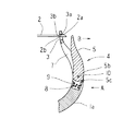
以下に、本発明におけるピアスの実施形態を図面に従って説明する。図1及び図2は、耳朶Yに装着した状態を示したものであり、図3は、耳朶Yから取り外した開放状態を示したものである。図示するように、略円形リング状のピアス本体1の一方の端部には、耳朶Yに形成したピアス孔に挿通する耳朶挿通用ピン2の後端を固着し、他方の端部には、耳朶挿通用ピン2が挿入するための挿入孔3が形成されている。耳朶挿通用ピン2の先端部には、挿入孔3の上部に設けられた係止面3aと係止する係止部2aが形成されており、また、ピアス本体1aの適宜位置に設けられた押付け機構4の押付け片5の上端部5aで、挿入孔3を挿通した耳朶挿通用ピン2の先端の固着位置2bを挿入孔3の内周面3bに押付けて、耳朶挿通用ピン2の固着状態を保持するように構成されている。また、図示するように、このピアス本体1は、軸着部6を介して本体1a及び本体1bを開閉自在に設けて、耳朶Yを装入したり、脱出できるようにしている。
【0010】
図4は、押付け機構4を示した分離斜視図であり、本体1aの適宜位置には、押付け機構4を収納するための収納部7が本体1aの一部を外周面から内周面に貫通して形成されており、この収納部7内には、コイルスプリング8を取り付けるための取付部9が形成されている。また、本例に限定されることなく、押付け機構4が収納でき、押付け片5が回動可能であれば、適宜深さで適宜形状の溝を形成して収納部としてもよい。本例では、コイルスプリング8を使用しているが、本例に限定されることなく、他の弾性部材であってもよい。
【0011】
図示するように、適宜形状に形成された押付け片5を上記収納部7にはめ込むようにして収納配置し、この押付け片5に設けられた孔部5bと本体1aに設けられた孔部1cに軸着部材10を挿入して、この押付け片5を回動自在となるように設けると共に、図5及び図6に示すように、上記コイルスプリング8の一端を収納部7内に形成されたコイルスプリング取付部9に取り付け、他端部を押付け片5の下端に形成されているコイルスプリング取付面5cに取り付けて、押付け片5をこのコイルスプリング8を介して一方向に弾性付勢させている。
【0012】
このコイルスプリング8の弾性力を利用して、押付け片5の上端部5aで挿入孔3内に位置している耳朶挿通用ピン2の先端の固着位置2bを挿入孔3の内周面3bに押付けて、耳朶挿通用ピン2の固着状態を保持するようにしている。
【0013】
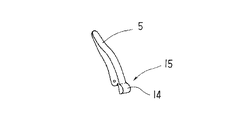
また、押付け片5には、回動操作を行い易いようにするために操作部を設けてもよい。例えば、図7R>7に示すように、押付け片5の背面部の一部を楕円形状等の板状の摘み片12を有する操作部13を設けて、この摘み片12を指で摘んで回動操作させたり、或はこの摘み片12を爪で引っ掛けて回動操作させる。また、図8R>8に示すように、押付け片5の下端の背面部に突起部14を有する操作部15を設けて、この突起部14を指または爪に引っ掛けて回動操作させる。或は、図9に示すように、押付け片の内側に開放方向に向けて押付け操作するための押部16を有する操作部17を設けるなど、適宜形状で適宜位置に設けることができる。
【0014】
また、図10及び図11は、他の実施形態を示した図面であり、この図面にしたがって説明すると、略円形リング状のピアス本体18の一方の端部に形成した筒部18aと、耳朶挿通用ピン19の後端に形成したリング状孔部19aとを軸着部材20を介して回動自在に軸着し、ピアス本体18の他方端部には、耳朶挿通用ピン19の先端部位が装着するための受け部21が設けられている。
【0015】
また、受け部21が設けられている側のピアス本体18の適宜位置には、先述した実施例と同様に、押付け機構22を収納するための収納部23が設けられており、適宜形状に形成された押付部材24をこの収納部23にはめ込むようにして収納配置し、この押付部材24に設けられた孔部24aと本体18に設けられた孔部18bに軸着部材10を挿入して、この押付部材24を回動自在となるように設けると共に、コイルスプリング8の一端を収納部23内に形成されたコイルスプリング取付部25に取り付け、他端部を押付部材24の後端に形成されているコイルスプリング取付面24bに取り付けて、この押付部材24をコイルスプリング8を介して一方向に弾性付勢させている。
【0016】
図12に示すように、押付部材24の先端には、リング状に形成された押付け部24cが設けられており、この押付け部24cに形成された挿入孔24dに受け部21に装着した耳朶挿通用ピン19の先端を挿入し、コイルスプリング8の弾性力を利用して耳朶挿通用ピン19の装着位置19bを受け部21の装着部位21aに押付けて、耳朶挿通用ピン19の固着状態を保持するように構成している。
【0017】
次に、上記した実施例の作用を説明する。本例におけるピアスを耳朶Yに装着する場合は、先ず、図3に示すように、ピアス本体1を軸着部6を介して外方に拡げて耳朶Yを装入できる状態にする。次いで、ピアス本体1の一端に固着して設けられた耳朶挿通用ピン2を耳朶Yに設けられたピアス孔に挿通し、この耳朶挿通用ピン2の先端部を他方の端部に形成された挿入孔3に挿入すると、耳朶挿通用ピン2の先端に形成された係止部2aが挿入孔3の上部に位置する係止面3aで係止する。
【0018】
このとき、本体1aに設けられている押付け機構4内に内蔵されているコイルスプリングの弾性力により、押付け片5の先端部5aが耳朶挿通用ピン2の先端の固着位置2bを挿入孔3の内周面3bに押付けて、止着するという装着手段からなるので、耳朶Yへの着脱が簡単に行えると共に、耳朶挿通用ピン2の固着状態を確実に保持することができる。
【0019】
また、耳朶Yからピアス本体1を取り外す場合について説明すると、図6に示すように、押付け片5の下端部位を軽くA方向へ押すことにより、耳朶挿通用ピン2の先端の固着位置2bを押付けていた押付け片5の先端部5aがB方向に向けて外れ、開放状態となり、図3に示すように、本体1a又は本体1bのどちらか一方を開放方向へ向けて広げるだけで、耳朶挿通用ピン2の先端部が挿入孔3から抜けるので、耳朶Yから簡単に取り外すことができる。また、図7から図9に示すように、押付け片5の適宜位置に適宜形状の操作部を設けることで、押付け片5の操作性が簡易になる。
【0020】
また、他の実施例の作用について説明すると、押付部材24の先端に、リング状に形成された押付け部24cを設け、この押付け部24cに形成された挿入孔24dに受け部21に装着した耳朶挿通用ピン19の先端を挿入し、コイルスプリング8の弾性力を利用して耳朶挿通用ピン19の装着位置19bを受け部21の装着部位21aに押付けて、耳朶挿通用ピン19の固着状態を保持するという装着手段を有することで、耳朶挿通用ピン19の固着状態を確実に保持すると共に、取り外す場合は、押付部材24の先端を指若しくは爪で開放方向に向けて引いたり、或はコイルスプリング取付面24bの背面部位を押すことで、押付部材24の先端が開放方向へ移動し、耳朶挿通用ピン19の先端の装着位置19bを押付部材24で押付けていた状態が解除されると共に、耳朶挿通用ピン19が挿入孔24dから抜けるので、簡単に耳朶Yから取り外すことができる。
【0021】
【発明の効果】
以上のことから明らかなように、本発明のピアスは、上記した押付け機構を採用することで、耳朶の裏側という操作しにくい場所でも、装着、取り外し行為を簡単に、確実に行うことを可能とすると共に、耳朶挿通用ピンが止着部材から不用意に外れることがなく、確実に固着状態を保持することを可能にしたピアスであり、耳朶挿通用ピンを止着する押付け機構をピアス本体に内蔵しているので、外部に露出することなく、装身具として体裁が良く、コンパクトで、デザイン性及び耐久性に優れたピアスを提供することができる。
【0022】
更に、押付け機構は、簡単な操作で押付けと解除が確実にできるため、その使用価値が極めて高く、又、構造が簡単であるから安価に量産することができる。
【図面の簡単な説明】
【図1】本発明におけるピアスの一実施例を示す正面図である。
【図2】図1における押付け機構の状態を示す一部切欠き拡大断面図である。
【図3】図1における装着状態を開放した状態を示す正面図である。
【図4】本発明におけるピアスの押付け機構を示す分離斜視図である。
【図5】図1における押付け機構の押付け片を開放した状態を示す正面図である。
【図6】図5における押付け機構の状態を示す一部切欠き拡大断面図である。
【図7】図1における押付け片に操作部を設けた状態を示す斜視図である。
【図8】図1における押付け片に他例の操作部を設けた状態を示す斜視図である。
【図9】図1における押付け片に更に他例の操作部を設けた状態を示す斜視図である。
【図10】本発明におけるピアスの他の実施例を示す正面図である。
【図11】図10における装着状態を開放した状態を示す正面図である。
【図12】図10における本発明ピアスの押付け機構を示す分離斜視図である。
【符号の説明】
1 ピアス本体
2 耳朶挿通用ピン
2b 固着位置
3 挿入孔
4 押付け機構
5 押付け片
6 軸着部
7 収納部
8 コイルスプリング
13,15,17 操作部
21 受け部[0001]
BACKGROUND OF THE INVENTION
The present invention relates to a pierced earring that is worn by inserting a pin through an earlobe, and more particularly to a pierced earring that reliably holds the pierced wearing state.
[0002]
[Prior art]
Conventionally, there are various types of piercings of this type, and various types have been proposed for mounting methods provided on the piercings. As a typical example, a mounting pin is inserted into a pierced hole drilled in the earlobe, and the pierced earring is attached by inserting and fixing the mounting pin into the insertion hole of a fastening device called a catch from the back side of the earlobe. It has been known.
[0003]
However, since this piercing is separate from the mounting pin and the catch, the mounting operation is performed on the back side of the earlobe by inserting the mounting pin through the insertion hole provided in the catch and fastening it, so the mounting operation is very It was troublesome. Moreover, since the mounting pin and the catch are separate bodies, there is also a risk that the catch that is a fastening tool may be lost. Furthermore, in this earring, since the catch is mounted in a state protruding from the back side of the earlobe, there is a difficulty in the design as an accessory.
[0004]
Japanese Patent Application Laid-Open No. 7-204016, for example, discloses a ring-shaped decorative body having a pin attached to one end through a shaft attachment member. These earrings are attached to the middle of the annular decorative body so as to be openable and closable via a shaft, and an opening through which a pin is inserted into the ear pad of the open end of the decorative body that is one narrow attachment member In general, a locking portion that engages with a locking groove of a pin is provided at the lower portion of the opening.
[0005]
[Problems to be solved by the invention]
However, in the above piercing, the tip of the pin comes into contact with the inner peripheral surface of the other sandwiching member that is opposed to it, so that if it is used repeatedly, the tip of the pin will be worn or removed during use. In addition to the inconvenience, there is a problem that the engagement between the pin and the locking portion cannot be surely performed, and it has been desired to eliminate these drawbacks.
[0006]
The present invention has been developed as a result of intensive studies in view of such conventional situations, and the object of the present invention is to attach and detach very easily even in places where it is difficult to perform mounting operations such as the back side of the earlobe. In addition to being able to act, it is possible to reliably hold the mounted state, and not only to be durable but also to be exposed to the outside.
[0007]
[Means for Solving the Problems]
In order to achieve the above object, the invention according to claim 1 is characterized in that the rear end of a pin is fixed to one end of a pierced body that is pivotably provided in the middle, and the tip of the pin is provided to the other end of the pierced body. The piercing body has a built-in pressing mechanism that inserts it into the insertion hole and presses the insertion position of this pin. The pressing mechanism is provided with a pressing piece that is pivotally attached in the middle of the piercing body, and this pressing piece is connected via a spring. The pierced earrings are elastically urged in one direction to press the pin located in the insertion hole at the upper end of the pressing piece into the insertion hole to maintain the inserted state of the pin.
[0008]
The invention according to
[0009]
DETAILED DESCRIPTION OF THE INVENTION
Hereinafter, embodiments of piercing according to the present invention will be described with reference to the drawings. 1 and 2 show a state where the earlobe Y is mounted, and FIG. 3 shows an open state where the earlobe Y is removed. As shown in the figure, the rear end of the
[0010]
FIG. 4 is an exploded perspective view showing the
[0011]
As shown in the figure, the
[0012]
Using the elastic force of the
[0013]
Further, the
[0014]
FIGS. 10 and 11 are views showing other embodiments. When described with reference to this drawing, a
[0015]
In addition, a
[0016]
As shown in FIG. 12, a
[0017]
Next, the operation of the above embodiment will be described. When attaching the earrings in this example to the earlobe Y, first, as shown in FIG. 3, the earring main body 1 is expanded outward through the
[0018]
At this time, due to the elastic force of the coil spring built in the
[0019]
Further, the case of removing the piercing body 1 from the earlobe Y will be described. As shown in FIG. 6 , the lower end portion of the
[0020]
Further, the operation of another embodiment will be described. A
[0021]
【The invention's effect】
As is clear from the above, the piercing of the present invention adopts the above-mentioned pressing mechanism, so that it is possible to easily and reliably perform the attaching and detaching action even in a difficult place to operate such as the back side of the earlobe. In addition, the earring insertion pin does not inadvertently come off the fastening member, and it is possible to securely hold the pierced earring, and a pressing mechanism for fastening the earlobe insertion pin to the piercing body. Since it is built-in, it is possible to provide a pierced earring that has a good appearance as an accessory, is compact, and has excellent design and durability without being exposed to the outside.
[0022]
Furthermore, since the pressing mechanism can be surely pressed and released by a simple operation, its use value is extremely high, and since the structure is simple, it can be mass-produced at low cost.
[Brief description of the drawings]
FIG. 1 is a front view showing an embodiment of a piercing according to the present invention.
2 is a partially cutaway enlarged cross-sectional view showing a state of the pressing mechanism in FIG. 1. FIG.
FIG. 3 is a front view showing a state in which the wearing state in FIG. 1 is released;
FIG. 4 is an exploded perspective view showing a piercing mechanism in the present invention.
FIG. 5 is a front view showing a state where a pressing piece of the pressing mechanism in FIG. 1 is released.
6 is an enlarged cross-sectional view partially cut away showing a state of the pressing mechanism in FIG. 5. FIG.
7 is a perspective view showing a state in which an operation unit is provided on the pressing piece in FIG. 1. FIG.
8 is a perspective view showing a state in which another operation portion is provided on the pressing piece in FIG. 1. FIG.
9 is a perspective view showing a state in which another operation portion is provided on the pressing piece in FIG. 1; FIG.
FIG. 10 is a front view showing another embodiment of the piercing according to the present invention.
11 is a front view showing a state in which the wearing state in FIG. 10 is released.
12 is an exploded perspective view showing the pressing mechanism of the piercing of the present invention in FIG.
[Explanation of symbols]
DESCRIPTION OF SYMBOLS 1 Pierce
Claims (2)
Priority Applications (1)
| Application Number | Priority Date | Filing Date | Title |
|---|---|---|---|
| JP2001243992A JP3790687B2 (en) | 2001-08-10 | 2001-08-10 | Earrings |
Applications Claiming Priority (1)
| Application Number | Priority Date | Filing Date | Title |
|---|---|---|---|
| JP2001243992A JP3790687B2 (en) | 2001-08-10 | 2001-08-10 | Earrings |
Publications (2)
| Publication Number | Publication Date |
|---|---|
| JP2003052424A JP2003052424A (en) | 2003-02-25 |
| JP3790687B2 true JP3790687B2 (en) | 2006-06-28 |
Family
ID=19073991
Family Applications (1)
| Application Number | Title | Priority Date | Filing Date |
|---|---|---|---|
| JP2001243992A Expired - Lifetime JP3790687B2 (en) | 2001-08-10 | 2001-08-10 | Earrings |
Country Status (1)
| Country | Link |
|---|---|
| JP (1) | JP3790687B2 (en) |
Families Citing this family (5)
| Publication number | Priority date | Publication date | Assignee | Title |
|---|---|---|---|---|
| KR200487902Y1 (en) * | 2017-12-14 | 2018-11-19 | 백승열 | Earring with good mineral content |
| KR102431080B1 (en) * | 2020-05-21 | 2022-08-10 | 홍경선 | Rotating fastening earrings for easy decoration replacement |
| KR20210146127A (en) * | 2020-05-26 | 2021-12-03 | 정강민 | A Rotating Type Earring |
| KR102458422B1 (en) * | 2022-08-05 | 2022-10-24 | 정강민 | Ring earrings that can be styled with two-type |
| WO2024029948A1 (en) * | 2022-08-05 | 2024-02-08 | 정강민 | Ring earring capable of being styled in two ways |
-
2001
- 2001-08-10 JP JP2001243992A patent/JP3790687B2/en not_active Expired - Lifetime
Also Published As
| Publication number | Publication date |
|---|---|
| JP2003052424A (en) | 2003-02-25 |
Similar Documents
| Publication | Publication Date | Title |
|---|---|---|
| JP5867048B2 (en) | CONNECTION DEVICE, BAND AND ELECTRONIC DEVICE PROVIDED WITH BAND | |
| JP4659671B2 (en) | Fastener with locking mechanism | |
| US5031430A (en) | Key ring | |
| JP2007160083A (en) | Clasp | |
| JP3790687B2 (en) | Earrings | |
| US5893278A (en) | Earring having an improved retaining mechanism | |
| JP2002065322A (en) | Structure of inside lock for accessories | |
| US6260382B1 (en) | Pierced earring | |
| JP3070034B2 (en) | Stoppers for accessories such as brooches | |
| KR200386157Y1 (en) | Key for locker room | |
| JP3040156U (en) | Mobile phone holder | |
| JP3811139B2 (en) | Earrings | |
| WO2022145461A1 (en) | Pin fastener and personal accessory using same | |
| JP2700782B2 (en) | Locking device for accessories such as tie pins | |
| JP3254511B2 (en) | Jewelry fastener | |
| JPS6485Y2 (en) | ||
| JP3111171U (en) | Accessories such as brooches | |
| JPH11113613A (en) | Catch for ornament | |
| KR200276913Y1 (en) | Earring | |
| KR200224143Y1 (en) | The chain coupling for ornament | |
| JP3932948B2 (en) | Drawer device | |
| JP3157405U (en) | Piercing locking structure | |
| JPH0119845Y2 (en) | ||
| JPH08256810A (en) | Fastener for necklace, etc. | |
| JP2784408B2 (en) | Earrings |
Legal Events
| Date | Code | Title | Description |
|---|---|---|---|
| A977 | Report on retrieval |
Free format text: JAPANESE INTERMEDIATE CODE: A971007 Effective date: 20050804 |
|
| A131 | Notification of reasons for refusal |
Free format text: JAPANESE INTERMEDIATE CODE: A131 Effective date: 20051220 |
|
| A521 | Written amendment |
Free format text: JAPANESE INTERMEDIATE CODE: A523 Effective date: 20060217 |
|
| TRDD | Decision of grant or rejection written | ||
| A01 | Written decision to grant a patent or to grant a registration (utility model) |
Free format text: JAPANESE INTERMEDIATE CODE: A01 Effective date: 20060322 |
|
| A61 | First payment of annual fees (during grant procedure) |
Free format text: JAPANESE INTERMEDIATE CODE: A61 Effective date: 20060403 |
|
| R150 | Certificate of patent or registration of utility model |
Free format text: JAPANESE INTERMEDIATE CODE: R150 Ref document number: 3790687 Country of ref document: JP Free format text: JAPANESE INTERMEDIATE CODE: R150 |
|
| FPAY | Renewal fee payment (event date is renewal date of database) |
Free format text: PAYMENT UNTIL: 20100407 Year of fee payment: 4 |
|
| R250 | Receipt of annual fees |
Free format text: JAPANESE INTERMEDIATE CODE: R250 |
|
| FPAY | Renewal fee payment (event date is renewal date of database) |
Free format text: PAYMENT UNTIL: 20100407 Year of fee payment: 4 |
|
| FPAY | Renewal fee payment (event date is renewal date of database) |
Free format text: PAYMENT UNTIL: 20110407 Year of fee payment: 5 |
|
| R250 | Receipt of annual fees |
Free format text: JAPANESE INTERMEDIATE CODE: R250 |
|
| R250 | Receipt of annual fees |
Free format text: JAPANESE INTERMEDIATE CODE: R250 |
|
| FPAY | Renewal fee payment (event date is renewal date of database) |
Free format text: PAYMENT UNTIL: 20120407 Year of fee payment: 6 |
|
| FPAY | Renewal fee payment (event date is renewal date of database) |
Free format text: PAYMENT UNTIL: 20130407 Year of fee payment: 7 |
|
| R250 | Receipt of annual fees |
Free format text: JAPANESE INTERMEDIATE CODE: R250 |
|
| FPAY | Renewal fee payment (event date is renewal date of database) |
Free format text: PAYMENT UNTIL: 20130407 Year of fee payment: 7 |
|
| FPAY | Renewal fee payment (event date is renewal date of database) |
Free format text: PAYMENT UNTIL: 20140407 Year of fee payment: 8 |
|
| R250 | Receipt of annual fees |
Free format text: JAPANESE INTERMEDIATE CODE: R250 |
|
| R250 | Receipt of annual fees |
Free format text: JAPANESE INTERMEDIATE CODE: R250 |
|
| R250 | Receipt of annual fees |
Free format text: JAPANESE INTERMEDIATE CODE: R250 |
|
| R250 | Receipt of annual fees |
Free format text: JAPANESE INTERMEDIATE CODE: R250 |
|
| R250 | Receipt of annual fees |
Free format text: JAPANESE INTERMEDIATE CODE: R250 |
|
| R250 | Receipt of annual fees |
Free format text: JAPANESE INTERMEDIATE CODE: R250 |
|
| R250 | Receipt of annual fees |
Free format text: JAPANESE INTERMEDIATE CODE: R250 |
|
| R250 | Receipt of annual fees |
Free format text: JAPANESE INTERMEDIATE CODE: R250 |