JP3804635B2 - Electric projection mechanism of injection molding machine - Google Patents
Electric projection mechanism of injection molding machine Download PDFInfo
- Publication number
- JP3804635B2 JP3804635B2 JP2003154978A JP2003154978A JP3804635B2 JP 3804635 B2 JP3804635 B2 JP 3804635B2 JP 2003154978 A JP2003154978 A JP 2003154978A JP 2003154978 A JP2003154978 A JP 2003154978A JP 3804635 B2 JP3804635 B2 JP 3804635B2
- Authority
- JP
- Japan
- Prior art keywords
- projecting
- plate
- screw shaft
- seat plate
- ball screw
- Prior art date
- Legal status (The legal status is an assumption and is not a legal conclusion. Google has not performed a legal analysis and makes no representation as to the accuracy of the status listed.)
- Expired - Fee Related
Links
- 238000001746 injection moulding Methods 0.000 title claims description 8
- 238000009434 installation Methods 0.000 claims description 8
- 230000000694 effects Effects 0.000 description 2
- 238000012423 maintenance Methods 0.000 description 2
- 238000000034 method Methods 0.000 description 2
- 239000006096 absorbing agent Substances 0.000 description 1
- 230000006835 compression Effects 0.000 description 1
- 238000007906 compression Methods 0.000 description 1
- 230000035939 shock Effects 0.000 description 1
Images


Landscapes
- Moulds For Moulding Plastics Or The Like (AREA)
- Injection Moulding Of Plastics Or The Like (AREA)
Description
【0001】
【発明の属する技術分野】
この発明は、射出成形機が備える電動式突出機構に関するものである。
【0002】
【従来の技術】
従来の電動式突出装置では、電動機の回転をボールナット部材とボールねじ軸と直線運動に変換する突出駆動装置を用い、そのボールねじ軸の端部に設けた突出板にボルトを相対的に移動するように設け、そのボルトに突出ロッドを突出板との間に緩衝部材を介在させて取付けている。(例えば、特許文献1。)
【0003】
【特許文献1】
特許第3129987号公報
【0004】
【発明が解決しようとする課題】
この従来の電動式突出装置にあっては、突出板が前進限に到達した際に発生する突破力を緩衝部材で吸収できるので、突出板を衝撃的に作動させたとしても、一定の範囲内での突出力を発生させられることができ、成形品を確実に離脱させることができる。
【0005】
しかしながら、前記緩衝部材が突出板と突出ロッドとの間に介在する構造であることから、
▲1▼ 突出ロッドの本数分の緩衝部材を有するボルトを必要とする。
▲2▼ 突出ロッドの着脱が困難である。
▲3▼ 突出ロッドの着脱の度にボルトの締め付け調整を必要とする。
などといった問題点があり、部品点数の増加等によりコスト高となるばかりでなく、メンテナンスや締め付け調整などに際しての作業性の効率を妨げる原因にもなっていることから、これら問題点の解決が課題となっている。
【0006】
この発明の目的とするところは、突出ロッドの動作に係る緩衝部材の配置をボールねじ軸と突出板の中間箇所に設定した構造とすることにより、ボールねじ軸への衝撃吸収効果を損なうことなく、前記従来の課題を解決することができる新たな射出成形機の電動式突出機構を提供することにある。
【0007】
【課題を解決するための手段】
前記目的によるこの発明は、可動盤背部の凹所内に並設した複数本の支持軸と、両支持軸に可動自在に挿通した突出板及び座板と、その突出板の前面に取付けて可動盤の前部内の突出穴に挿入した突出ロッドと、外端にプーリを備えるボールナット部材をケーシングの内部に回転自在に有し、そのボールナット部材にボールねじ軸を螺合して設けた突出駆動装置とからなり、
その突出駆動装置を支持軸の軸端にケーシングを取付けて可動盤に固設するとともに、ボールねじ軸の内端を座板に止着して座板背部に位置させ、その座板と突出板とを両板間に緩衝部材を配置して可動自在に連係ボルトにより連結し、かつ座板にストッパを突出板との間に所要の間隙を設けて突設してなる、というものである。
【0008】
またこの発明は、可動盤背部の凹所の蓋部材を兼ねる設置板と、その設置板に取付けて凹所内に設けた支持軸と、その支持軸に可動自在に挿通した突出板及び中央に穴部を有する座板と、その突出板の前面に取付けて可動盤の前部内の突出穴に挿入した突出ロッドと、外端にプーリを備えたボールねじ軸をボールナット部材に回転自在に螺合して設けた突出駆動装置とからなり、
その突出駆動装置を設置板にボールねじ軸の外端側を回転自在に取付けて可動盤に固設するとともに、ボールナット部材を座板の中央に止着して該座板の穴部から突出板の背部にボールねじ軸の内端を位置させ、その座板と突出板とを両板間に緩衝部材を配置して可動自在に連係ボルトにより連結してなる、というものである。
【0009】
さらに、この発明の前記緩衝部材は突出板を常時前方に弾圧するコイルばねからなる、というものである。
【0010】
【発明の実施の形態】
図1は、この発明に係る電動式突出機構を備えた射出成形機を例示するものであって、1は固定盤、2は受圧盤で両盤の間に可動盤3がタイバー4に挿通して進退自在に設けてあり、その可動盤3の背部に受圧盤2とにわたるトグル型締機構5が連結してある。
また可動盤3の固定盤1との対向面には固定盤側の固定型6bと型閉する可動型6aが取付けてあり、その可動型6aの内部に突出ピン7を備えた型内突出板8が設けてある。
この型内突出板8には図では省略するが、可動盤3の背部中央に設けた電動機9を駆動源とする突出機構の後記する突出ロッドが当接してある。
【0011】
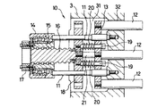
図2及び図3は、この発明の実施形態を示すもので、電動式突出機構は前記可動盤3の背面中央に形成した凹所31に設けられている。
図中11は可動盤3の背部に並設した複数本の支持軸で、この支持軸11には前面に突出ロッド12を取付けた突出板13が可動自在に挿通してあり、その突出ロッド12の先端部は可動盤の前部内の突出孔32に挿入位置して、型内突出板8に当接するようにしてある。
【0012】
この突出ロッド12を進退動作する突出駆動装置は、ケーシング14にベアリングを介して回転自在に収められたボールナット部材15と、そのボールナット部材15に螺合したボールねじ軸16とからなり、ボールナット部材15の回転がボールねじ軸16の直線移動に変換されるように、ケーシング14を支持軸11の軸端に取付けて可動盤側に固設するとともに、ボールナット部材15の外端にプーリ17を取付けて、前記電動機9の回転をボールナット部材15に伝達できるようにしてある。
【0013】
前記ボールねじ軸16の内端には、前記支持軸11に挿通した座板18が止着してあり、その座板18に複数本の連係ボルト19が軸周囲にコイルばねによる緩衝部材20を嵌めて、突出板13側からねじ着してあり、これにより突出板13は連係ボルト19を介して座板18に連結され、また緩衝部材20により常時前方に弾圧されて、非作動時に座板18との間に連係ボルト19の長分の間隔が保たれている。
【0014】
また座板18の中央には、突出板13との間に所要間隙を設けて位置するストッパ21が突設してあり、このストッパ21によって突出時の抵抗により緩衝部材20を圧縮して後退する突出板13を受け止めて、ボールねじ軸16と共に突出板13の前進移動ができるようにしてある。
【0015】
前記構成では、型開後にボールナット部材15の回転によりボールねじ軸16が前進移動すると、座板18と突出板13が緩衝部材20を介して共に前進移動する。これにより突出ロッド12の先端が型内突出板8(図1参照)と接して共に前進移動する。この前進移動は図3に示す前進限まで行われて、図示しない成形品を可動型から突き出す。
【0016】
この突出動作において、型内突出板8が成形品を突き出すときに突出板側が受ける衝撃は、突出板13がストッパ21に当たるところまで緩衝部材20が圧縮されることにより吸収され、これによりボールねじ軸16に対する衝撃も緩衝されるので、突出動作ごとのボールナット部材15とボールねじ軸16との螺合部位に掛かる負担も軽減され、以後の前進限までの突出はストッパ21がボールねじ軸16とともに前進して突出板13を押圧することにより行われる。
【0017】
また成形品を突き出した後は、突出板13に対する負荷がなくなるので、緩衝部材20が伸長して突出板13を元に押し戻す。これにより突出板13はストッパ21から離れる。突き出し後にはボールナット部材15が逆回転されて、ボールねじ軸16が後退限まで移動するので、突出板13は連係ボルト19により後退位置まで引き戻され、その後退過程で緩衝部材20による前記押し戻が行われて次の突出動作に備えられる。
【0018】
この突出動作は、一回の操作で成形品の完全な突出離型が行われないときがあるので、通常は複数回を繰返し行っている。この場合、2回目以後の後退移動は後退限まで行わず短ストロークで行っているが、前記構成では連係ボルト19と緩衝部材20及びストッパ21によつて、ボールねじ軸16の進退移動に突出板13が応答して、その都度、成形品の突出離型が確実に行われるようになる。
【0019】
図4は、前記実施形態とは反対に、ボールねじ軸16を支持軸11と共に可動盤3側に並行に取付け、そのボールねじ軸16に螺合したボールナット部材15を、ボールねじ軸16の回転により直線移動して突出駆動装置を構成した場合の他の実施形態を示すものである。
【0020】
支持軸11とボールねじ軸16は、可動盤3の背面に取付けた凹所31の蓋部材を兼ねる設置板22に、支持軸11は一端を固設して、ボールねじ軸16は軸部を軸受部材23に回転自在に軸承して可動盤側に設けられ、そのボールねじ軸16の外端にプーリ17を取付けて、ボールねじ軸16を電動機により回転できるようにしてある。
【0021】
また支持軸11には、突出ロッド12を前面に取付けた突出板13と、中央に穴部を有する座板18とが可動自在に挿通してあり、その座板18の中央にボールナット部材15の内端が止着してある。また座板18には連係ボルト19が軸周囲にコイルばねによる緩衝部材20を嵌めて、突出板13側からねじ着してあり、これにより突出板13は連係ボルト19を介して座板18に連結され、また緩衝部材20により常時前方に弾圧されて、非作動時に座板18との間に連係ボルト19の長分の間隔が保たれている。
【0022】
このような構成では、座板18の中央から突出板13側に、定位置で回転するボールねじ軸16が突出し、その先端が突出板13との間に所要間隙を設けて臨むので、その先端をストッパとして、突出時の抵抗により緩衝部材20を圧縮して後退する突出板13を受け止めることができる。
【0023】
したがって、ボールねじ軸16が回転するとボールナット部材15が座板18と共に前進移動して前記実施形態と同様に突出作動し、また逆回転による後退移動して次の突出作動に備える。この後退過程で緩衝部材20による前記突出板13の押し戻が行われて、次の突出動作に備えられる。
なお、支持軸11と連係ボルト19は複数本でもよく、連係ボルト19ごとに緩衝部材20が設けられる。
【0024】
上述のように、突出駆動装置のボールねじ軸16又はボールナット部15に座板18を止着し、その座板18と所要数の突出ロッド12を有する突出板13とを、緩衝部材20と共に連係ボルト19により連係したこの発明では、突出ロッドごとに緩衝部材を設けた場合に比べて、緩衝部材の数を低減でき、また緩衝部材に関係なく突出ロッドの着脱が可動型の前面側から行えるので、成形品の形態や大きさに応じた本数の加減も簡単にできるばかりか、機構自体は本数により変わることはないので、その都度メンテナンスを行う必要もなく、突出ロッドの配置パターンの変更による機構修正も不要となる。さらに突出作動時のボールナット部材とボールねじ軸の螺合部位に対する衝撃が緩衝されるので、ボールねじの負担が軽減され寿命が長くなる等の諸効果を有する。
【図面の簡単な説明】
【図1】 この発明に係る電動式突出機構を備えた射出成形機の側面図である。
【図2】 この発明に係る電動式突出機構の一実施形態の縦断側面図である。
【図3】 同じく突出作動時の縦断側面図である。
【図4】 この発明の電動式突出機構の他の実施形態の略示縦断側面図である。
【符号の説明】
1 固定盤
2 受圧盤
3 可動盤
4 タイバー
5 トグル型締機構
6a 可動型
6b 固定型
7 突出ピン
8 型内突出板
9 電動機
11 支持軸
12 突出ロッド
13 突出板
14 ケーシング
15 ボールナット部材
16 ボールねじ軸
17 プーリ
18 座板
19 連係ボルト
20 緩衝部材(コイルばね)
21 ストッパ
22 設置板
23 軸受部材
31 凹所
32 突出孔[0001]
BACKGROUND OF THE INVENTION
The present invention relates to an electric projection mechanism provided in an injection molding machine.
[0002]
[Prior art]
In a conventional electric projecting device, a projecting drive device that converts the rotation of the motor into a linear motion between the ball nut member and the ball screw shaft is used, and the bolt is moved relatively to the projecting plate provided at the end of the ball screw shaft. The projecting rod is attached to the bolt with a buffer member interposed between the projecting plate and the projecting plate. (For example, Patent Document 1)
[0003]
[Patent Document 1]
Japanese Patent No. 3129987 [0004]
[Problems to be solved by the invention]
In this conventional electric projecting device, the breaking force generated when the projecting plate reaches the forward limit can be absorbed by the buffer member, so even if the projecting plate is shocked, it is within a certain range. Can be generated, and the molded product can be reliably detached.
[0005]
However, since the buffer member is a structure interposed between the protruding plate and the protruding rod,
(1) A bolt having cushioning members corresponding to the number of protruding rods is required.
(2) It is difficult to attach and detach the protruding rod.
(3) It is necessary to adjust the bolt tightening each time the protruding rod is attached or detached.
In addition to increasing costs due to an increase in the number of parts, etc., it also hinders the efficiency of workability during maintenance and tightening adjustments. It has become.
[0006]
The object of the present invention is to provide a structure in which the buffer member relating to the operation of the protruding rod is arranged at an intermediate position between the ball screw shaft and the protruding plate, without impairing the impact absorbing effect on the ball screw shaft. Another object of the present invention is to provide an electric projection mechanism for a new injection molding machine that can solve the conventional problems.
[0007]
[Means for Solving the Problems]
The present invention according to the above-described object includes a plurality of support shafts arranged in parallel in a recess in the back of the movable platen, a projecting plate and a seat plate that are movably inserted into both support shafts, and a movable plate attached to the front surface of the projecting plate. A projecting drive that has a projecting rod inserted into a projecting hole in the front part of the housing and a ball nut member having a pulley at the outer end, which is rotatable inside the casing and screwed with a ball screw shaft to the ball nut member Consisting of equipment,
The projecting drive unit is fixed to the movable plate by attaching a casing to the shaft end of the support shaft, and the inner end of the ball screw shaft is fixed to the seat plate and positioned on the back of the seat plate. A buffer member is disposed between the two plates and is movably connected by a linkage bolt, and a stopper is provided on the seat plate with a required gap provided between the projection plate and the projection plate.
[0008]
The present invention also includes an installation plate that also serves as a lid member for the recess at the back of the movable platen, a support shaft that is attached to the installation plate and provided in the recess, a protruding plate that is movably inserted into the support shaft, and a hole in the center. A seat plate having a portion, a projecting rod attached to the front surface of the projecting plate and inserted into a projecting hole in the front portion of the movable platen, and a ball screw shaft having a pulley at the outer end are rotatably screwed to the ball nut member. And a projecting drive device provided
The projecting drive device is fixed to the movable plate by rotatably mounting the outer end side of the ball screw shaft to the installation plate, and the ball nut member is fixed to the center of the seat plate and projects from the hole of the seat plate. The inner end of the ball screw shaft is positioned on the back of the plate, and the seat plate and the protruding plate are movably connected by a connecting bolt with a buffer member disposed between the two plates.
[0009]
Furthermore, the buffer member according to the present invention comprises a coil spring that constantly presses the protruding plate forward.
[0010]
DETAILED DESCRIPTION OF THE INVENTION
FIG. 1 illustrates an injection molding machine equipped with an electric projection mechanism according to the present invention, wherein 1 is a stationary platen, 2 is a pressure receiving plate, and a
Further, a
Although not shown in the figure, the in-
[0011]
2 and 3 show an embodiment of the present invention, and the electric projecting mechanism is provided in a
In the figure,
[0012]
The projecting drive device for moving the projecting
[0013]
A
[0014]
In addition, a
[0015]
In the above configuration, when the
[0016]
In this projecting operation, the impact received by the projecting plate side when the in-
[0017]
In addition, since the load on the protruding
[0018]
This projecting operation is usually repeated a plurality of times because there is a case where the complete projecting of the molded product is not performed by one operation. In this case, the second and subsequent retreat movements are performed with a short stroke without performing the retreat limit, but in the above configuration, the projecting plate is used for the reciprocation of the
[0019]
4, contrary to the above embodiment, the
[0020]
The
[0021]
A projecting
[0022]
In such a configuration, the
[0023]
Therefore, when the
A plurality of
[0024]
As described above, the
[Brief description of the drawings]
FIG. 1 is a side view of an injection molding machine provided with an electric projection mechanism according to the present invention.
FIG. 2 is a longitudinal sectional side view of an embodiment of an electric projecting mechanism according to the present invention.
FIG. 3 is a longitudinal side view of the same when projecting.
FIG. 4 is a schematic longitudinal sectional side view of another embodiment of the electric projecting mechanism of the present invention.
[Explanation of symbols]
DESCRIPTION OF SYMBOLS 1
21
Claims (3)
その突出駆動装置を支持軸11,11の軸端にケーシング14を取付けて可動盤3側に固設するとともに、ボールねじ軸16の内端を座板18に止着して座板背方に位置させ、その座板18と突出板13とを両板間に緩衝部材20を配置して可動自在に連係ボルト19により連結し、かつ座板18にストッパ21を突出板13との間に所要の間隙を設けて突設してなることを特徴とする射出成形機の電動式突出機構。A plurality of support shafts 11 and 11 arranged in parallel in a recess 31 on the back surface of the movable platen, a protruding plate 13 and a seat plate 18 that are movably inserted through the support shafts 11 and 11, and a front surface of the protruding plate 13. A projecting rod 12 attached and inserted into a projecting hole 32 in the front part of the movable platen 3 and a ball nut member 15 having a pulley 17 at the outer end are rotatably provided inside the casing 14. A projecting drive device provided by screwing the screw shaft 16;
The projecting drive device is fixed to the movable platen 3 side by attaching a casing 14 to the shaft ends of the support shafts 11, 11, and the inner end of the ball screw shaft 16 is fixed to the seat plate 18 to be behind the seat plate. The seat plate 18 and the projecting plate 13 are positioned, and a buffer member 20 is disposed between the two plates, and is movably coupled by a linkage bolt 19. A stopper 21 is required between the seat plate 18 and the projecting plate 13. An electric projecting mechanism for an injection molding machine, wherein the projecting mechanism is provided with a gap therebetween.
その突出駆動装置を設置板22にボールねじ軸16の外端側を回転自在に取付けて可動盤3に固設するとともに、ボールナット部材15を座板18の中央に止着して該座板の穴部から突出板13の背方にボールねじ軸16の内端を位置させ、その座板18と突出板13とを両板間に緩衝部材20を配置して可動自在に連係ボルト19により連結してなることを特徴とする射出成形機の電動式突出機構。An installation plate 22 that also serves as a lid member for the recess 31 on the back of the movable platen, a support shaft 11 that is attached to the installation plate 22 and provided in the recess, a protruding plate 13 that is movably inserted into the support shaft 11 and a center. A seat plate 18 having a hole, a projecting rod 12 attached to the front surface of the projecting plate 11 and inserted into a projecting hole 32 in the front portion of the movable platen 3, and a ball screw shaft 16 having a pulley 17 at the outer end A projecting drive device that is rotatably engaged with the nut member 15;
The projecting drive device is attached to the installation plate 22 so that the outer end side of the ball screw shaft 16 is rotatably mounted and fixed to the movable plate 3, and the ball nut member 15 is fixed to the center of the seat plate 18. The inner end of the ball screw shaft 16 is positioned behind the projecting plate 13 from the hole portion, and a buffer member 20 is disposed between the seat plate 18 and the projecting plate 13 between the two plates by a linking bolt 19 to be movable. An electric projection mechanism for an injection molding machine, characterized by being connected.
Priority Applications (1)
| Application Number | Priority Date | Filing Date | Title |
|---|---|---|---|
| JP2003154978A JP3804635B2 (en) | 2003-05-30 | 2003-05-30 | Electric projection mechanism of injection molding machine |
Applications Claiming Priority (1)
| Application Number | Priority Date | Filing Date | Title |
|---|---|---|---|
| JP2003154978A JP3804635B2 (en) | 2003-05-30 | 2003-05-30 | Electric projection mechanism of injection molding machine |
Publications (3)
| Publication Number | Publication Date |
|---|---|
| JP2004351869A JP2004351869A (en) | 2004-12-16 |
| JP2004351869A5 JP2004351869A5 (en) | 2005-06-30 |
| JP3804635B2 true JP3804635B2 (en) | 2006-08-02 |
Family
ID=34049482
Family Applications (1)
| Application Number | Title | Priority Date | Filing Date |
|---|---|---|---|
| JP2003154978A Expired - Fee Related JP3804635B2 (en) | 2003-05-30 | 2003-05-30 | Electric projection mechanism of injection molding machine |
Country Status (1)
| Country | Link |
|---|---|
| JP (1) | JP3804635B2 (en) |
Families Citing this family (2)
| Publication number | Priority date | Publication date | Assignee | Title |
|---|---|---|---|---|
| DE102008011772A1 (en) * | 2008-02-28 | 2009-09-03 | Bernd Hansen | separating device |
| JP6725457B2 (en) * | 2017-07-07 | 2020-07-22 | 日精樹脂工業株式会社 | Ejector |
-
2003
- 2003-05-30 JP JP2003154978A patent/JP3804635B2/en not_active Expired - Fee Related
Also Published As
| Publication number | Publication date |
|---|---|
| JP2004351869A (en) | 2004-12-16 |
Similar Documents
| Publication | Publication Date | Title |
|---|---|---|
| EP1726427B1 (en) | Mold clamping device and mold clamping method | |
| TW558492B (en) | Electromotive mold opening/closing device | |
| CN101934576B (en) | Clamping device | |
| US20050170038A1 (en) | Movable-die support device and die clamping unit | |
| JPH08183079A (en) | Movable member-propelling mechanism of motor-driven injection molding machine | |
| CN100496934C (en) | Supporting device for movable portion and die clamping unit | |
| JP4516097B2 (en) | Clamping device | |
| JP3804635B2 (en) | Electric projection mechanism of injection molding machine | |
| JP4914189B2 (en) | Injection molding machine | |
| KR100944355B1 (en) | Percussion device | |
| JP2002154146A (en) | Motor driven type opening/closing device | |
| JP3927066B2 (en) | Clamping device | |
| JP3790511B2 (en) | Molding device for injection molding machine | |
| JP2010240676A (en) | Ejecting device for molding machine | |
| JP3426992B2 (en) | Device for preventing overload of drive unit in injection molding machine | |
| JP6026212B2 (en) | Electric die casting machine | |
| EP0620095A3 (en) | Injection moulding machine, in particular plastic injection moulding machine. | |
| CN115139454A (en) | A die assembly that is used for quick locking of injection molding machine, die casting machine, punching machine | |
| JP2002327826A (en) | Ball screw device and motor driven closing gear for injection molding machine | |
| JP3728232B2 (en) | Molding device clamping machine | |
| JP2004330552A (en) | Mold clamping device | |
| CN217476534U (en) | Full-electric injection molding machine | |
| JP4740054B2 (en) | Toggle mold clamping device for injection molding machine | |
| JP2003039503A (en) | Drive device | |
| JP3562717B2 (en) | Traction type electric injection molding machine |
Legal Events
| Date | Code | Title | Description |
|---|---|---|---|
| A521 | Written amendment |
Free format text: JAPANESE INTERMEDIATE CODE: A523 Effective date: 20041018 |
|
| A621 | Written request for application examination |
Free format text: JAPANESE INTERMEDIATE CODE: A621 Effective date: 20041018 |
|
| A977 | Report on retrieval |
Free format text: JAPANESE INTERMEDIATE CODE: A971007 Effective date: 20050621 |
|
| A131 | Notification of reasons for refusal |
Free format text: JAPANESE INTERMEDIATE CODE: A131 Effective date: 20060110 |
|
| A521 | Written amendment |
Free format text: JAPANESE INTERMEDIATE CODE: A523 Effective date: 20060313 Free format text: JAPANESE INTERMEDIATE CODE: A821 Effective date: 20060313 |
|
| TRDD | Decision of grant or rejection written | ||
| A01 | Written decision to grant a patent or to grant a registration (utility model) |
Free format text: JAPANESE INTERMEDIATE CODE: A01 Effective date: 20060411 |
|
| A61 | First payment of annual fees (during grant procedure) |
Free format text: JAPANESE INTERMEDIATE CODE: A61 Effective date: 20060501 |
|
| R150 | Certificate of patent or registration of utility model |
Free format text: JAPANESE INTERMEDIATE CODE: R150 |
|
| FPAY | Renewal fee payment (event date is renewal date of database) |
Free format text: PAYMENT UNTIL: 20100519 Year of fee payment: 4 |
|
| FPAY | Renewal fee payment (event date is renewal date of database) |
Free format text: PAYMENT UNTIL: 20100519 Year of fee payment: 4 |
|
| FPAY | Renewal fee payment (event date is renewal date of database) |
Free format text: PAYMENT UNTIL: 20110519 Year of fee payment: 5 |
|
| FPAY | Renewal fee payment (event date is renewal date of database) |
Free format text: PAYMENT UNTIL: 20110519 Year of fee payment: 5 |
|
| FPAY | Renewal fee payment (event date is renewal date of database) |
Free format text: PAYMENT UNTIL: 20120519 Year of fee payment: 6 |
|
| FPAY | Renewal fee payment (event date is renewal date of database) |
Free format text: PAYMENT UNTIL: 20120519 Year of fee payment: 6 |
|
| FPAY | Renewal fee payment (event date is renewal date of database) |
Free format text: PAYMENT UNTIL: 20150519 Year of fee payment: 9 |
|
| LAPS | Cancellation because of no payment of annual fees |